

Page 1

INVERTER
Plug-in option
FR-A8AVP Instruction Manual (For Inverter/Converter Switching)
Changeover between inverter and
high power factor converter
Compatible inverters: FR-A842-07700(315K) to 12120(500K)
OUTLINE
1
INVERTER-TO-
CONVERTER
CONVERSION
INSTALLATION AND
WIRING
PRECAUTIONS FOR USE
OF THE CONVERTER
PARAMETERS
PROTECTIVE FUNCTIONS
PRECAUTIONS FOR
MAINTENANCE AND
INSPECTION
SPECIFICATIONS
2
3
4
5
6
7
8
CONVERTER-TO-
INVERTER CONVERSION
9
Page 2
Thank you for choosing this Mitsubishi Electric inverter plug-in option.
WARNING
CAUTION
CAUTION
This Instruction Manual provides handling information and precautions for use of the this product. Incorrect handling might cause
an unexpected fault. Before using this product, always read this Instruction Manual carefully to ensure proper use.
Please forward this Instruction Manual to the end user.
Injury prevention
Safety instructions
Do not attempt to install, operate, maintain or inspect this
product until you have read through this Instruction Manual
and appended documents carefully and can use the
equipment correctly. Do not use this product until you have a
full knowledge of the equipment, safety information and
instructions.
In this Instruction Manual, the safety instruction levels are
classified into "WARNING" and "CAUTION"
Incorrect handling may cause
hazardous conditions, resulting in
death or severe injury.
Incorrect handling may cause
hazardous conditions, resulting in
medium or slight injury, or may cause
only material damage.
Note that even the level may lead to a
serious consequence depending on conditions.
Be sure to follow the instructions of both levels as they are
critical to personnel safety.
Electric shock prevention
WARNING
Do not remove the front cover or the wiring cover while the
inverter or the high power factor converter (converted from the
inverter, hereafter called "converter") is powered ON. Do not
operate the inverter/converter with any cover or wiring cover
removed, as accidental contact with exposed high-voltage
terminals and internal components may occur, resulting in an
electrical shock.
Even if power is OFF, do not remove the front cover except for
wiring or periodic inspection as the inside of the inverter/
converter is charged. Doing so may cause an electric shock.
Before wiring or inspection, check that the LED display of the
operation panel is OFF. Any person who is involved in wiring or
inspection shall wait for 10 minutes or longer after the power
supply has been cut off, and check that there are no residual
voltage using a tester or the like. The capacitor is charged with
high voltage for some time after power OFF, and it is dangerous.
The inverter/converter must be earthed (grounded). Earthing
(grounding) must conform to the requirements of national and
local safety regulations and electrical code (NEC section 250,
IEC 61140 class 1 and other applicable standards).
Any person who is involved in wiring or inspection of this product
shall be fully competent to do the work.
The inverter/converter must be installed before wiring.
Otherwise, electric shock or injury may result.
Do not touch the setting dial or keys with wet hands. Doing so
may cause an electric shock.
Do not subject the cables to scratches, excessive stress, heavy
loads or pinching. Doing so may cause an electric shock.
Do not change the cooling fan while the inverter/converter is
powered ON as it is dangerous.
Do not touch the printed circuit board or handle the cables with
wet hands. Doing so may cause an electric shock.
Fire prevention
CAUTION
The inverter/converter must be installed on a nonflammable wall
without holes. Installing it to or near flammable material can
cause a fire.
If the inverter/converter has become faulty, its power must be
switched OFF. A continuous flow of large current may cause a
fire.
Be sure to perform daily and periodic inspections as specified in
the Instruction Manual. If the inverter/converter is used without
any inspection, a burst, breakage, or a fire may occur.
CAUTION
The voltage applied to each terminal must be as specified in the
Instruction Manual. Otherwise a burst, damage, etc. may occur.
The cables must be connected to the correct terminals.
Otherwise a burst, damage, etc. may occur.
The polarity (+ and -) must be correct. Otherwise a burst,
damage, etc. may occur.
While power is ON or for some time after power-OFF, do not
touch the inverter/converter, reactor 1, reactor 2, phase
detection transformer box, filter capacitor, and inrush current
limit resistor as they will be extremely hot. Doing so may cause a
burn.
Additional instructions
The following instructions must be also followed. If the inverter/
converter is handled incorrectly, it may cause an unexpected
fault, injury, or electric shock.
CAUTION
Transportation and installation
The inverter/converter must be transported in correct method
that corresponds to the weight. Failure to do so may lead to
injuries.
Do not stack the boxes containing products higher than the
number recommended.
The inverter/converter must be installed in a position where it
withstands the weight of the product according to the information
in the Instruction Manual.
Do not install or operate the inverter/converter if it is damaged or
has parts missing.
When carrying the inverter/converter, do not hold it by the front
cover. Doing so may cause a fall or failure.
Do not stand or rest heavy objects on the inverter/converter.
The installing orientation of the inverter/converter must be
correct.
Foreign conductive objects must be prevented from entering the
inverter/converter. That includes screws and metal fragments or
other flammable substance such as oil.
As the inverter/converter is a precision instrument, do not drop
or subject it to impact.
The surrounding air temperature must be between 10 and +50°C
(non-freezing). Otherwise, the inverter/converter may be
damaged.
The ambient humidity must be 95% RH or less (non-
condensing). Otherwise, the inverter/converter may be
damaged. (For the details, refer to page 24.)
The temporary storage temperature (applicable to a short limited
time such as a transportation time) must be between -20 and
+65°C. Otherwise, the inverter/converter may be damaged.
The inverter/converter must be used indoors (without corrosive
gas, flammable gas, oil mist, dust and dirt etc.) Otherwise, the
inverter/converter may be damaged.
The inverter/converter must be used at an altitude of 2500 m or
less, with 2.9 m/s
X, Y, Z axes). Otherwise, the inverter/converter may be
damaged. (For the details, refer to page 24.)
If halogen-based materials (fluorine, chlorine, bromine, iodine,
etc.), included in fumigants to sterilize or disinfect wooden
packages, infiltrate into this product, the product may be
damaged. Prevent residual fumigant components from being
infiltrated into the package, or use an alternative sterilization or
disinfection method (heat disinfection, etc.). Note that
sterilization or disinfection of wooden package should be
performed before packing.
Test operation
Before starting the test operation, confirm or adjust the
parameter settings. Failure to do so may cause some machines
to make unexpected motions.
Before starting the operation, check the wiring of each peripheral
device. Faulty wiring may cause some machines to make
expected motions.
2
or less vibration at 10 to 55 Hz (directions of
Safety instructions
1
Page 3

WARNING
Usage
Any person must stay away from the equipment when the retry
function is set as the inverter/converter will restart suddenly after
its output shutoff.
Depending on the function settings, the inverter/converter does
not stop its output even when the STOP/RESET key on the
operation panel is pressed. To prepare for it, provide a separate
circuit and switch (to turn OFF the power or to take other
actions) for an emergency stop.
Be sure to turn OFF the start (STF/STR) signal before clearing
the fault as the inverter/converter will restart the motor suddenly
after a fault clear.
Use only the specified inverters for the connection with the
converter. Connection of any other electrical equipment to the
output of the converter may damage the equipment.
Do not modify the inverter/converter.
Do not remove any part which is not instructed to be removed in
the Instruction Manual. Doing so may lead to a failure or
damage.
CAUTION
Usage
Do not start or stop the inverter/converter frequently with a
magnetic contactor on its input side. Doing so may shorten the
life of the inverter/converter.
Use a noise filter or other means to minimize the
electromagnetic interference with other electronic equipment
used nearby the inverter/converter.
As all parameters return to their initial values after the Parameter
clear or All parameter clear is performed, the parameters must
be set again as required before the operation is started.
Before running an inverter/converter which have been stored
and not been operated for a long period, perform an inspection
and a test operation.
To avoid damage due to static electricity, static electricity in your
body must be discharged before you touch the inverter/
converter.
Emergency stop
A safety backup such as an emergency brake must be provided
for devices or equipment in a system to prevent hazardous
conditions in case of failure of the inverter/converter or its
external controller.
If a breaker on the input side of the inverter/converter is tripped,
the wiring must be checked for a fault (such as short circuit), and
internal parts of the inverter/converter for a damage, etc. The
cause of the trip must be identified and removed before turning
ON the power of the breaker.
When any fault occurs, take an appropriate corrective action,
then reset the inverter/converter, and resume the operation.
Maintenance, inspection and parts replacement
Do not carry out a megger (insulation resistance) test on the
control circuit of the inverter/converter.
Disposal
This product must be treated as industrial waste.
General instruction
For clarity purpose, illustrations in this Instruction Manual may
be drawn with covers or safety guards removed. Ensure all
covers and safety guards are properly installed prior to starting
operation.
2
Safety instructions
Page 4

CONTENTS
1 OUTLINE 7
1.1 Pre-operation instructions 8
1.1.1 Unpacking and checking the product................................................................................................................9
1.1.2 Component names .........................................................................................................................................10
1.2 Pre-installation instructions for the FR-A8AVP 11
1.3 Installing the FR-A8AVP 11
2 INVERTER-TO-CONVERTER CONVERSION 13
2.1 Conversion flowchart 14
2.2 Conversion procedure 15
2.2.1 Preparation for the conversion........................................................................................................................15
2.2.2 Inverter-to-converter conversion (Pr.328).......................................................................................................16
2.2.3 Application of stickers supplied with the product ............................................................................................17
2.3 Troubleshooting 18
3 INSTALLATION AND WIRING 19
3.1 Peripheral devices 20
3.1.1 Converter and peripheral devices...................................................................................................................20
3.2 Selection of breaker, magnetic contactor, and fuse 21
3.3 Compatible inverter for the high power factor converter 22
3.3.1 Applicable inverter capacity............................................................................................................................22
3.3.2 Inverter parameter settings.............................................................................................................................23
3.4 Installation of the converter and enclosure design 24
3.4.1 Converter installation environment .................................................................................................................24
3.4.2 Cooling system types for converter enclosure ................................................................................................26
3.4.3 Installation of the converter.............................................................................................................................27
3.4.4 Protruding the heatsink through a panel.........................................................................................................28
3.5 Installation of stand-alone options for converter 29
3.5.1 Installation of the reactor 1 (FR-A8BL1) and reactor 2 (FR-A8BL2)...............................................................29
3.5.2 Installation of the phase detection transformer box (FR-A8VPB) ...................................................................30
3.5.3 Installation of the filter capacitor (FR-A8BC) ..................................................................................................33
3.5.4 Installation of the dedicated circuit parts for inrush current protection (FR-A8MC) ........................................34
3.5.5 Terminals of stand-alone options for the converter ........................................................................................36
3.6 Main circuit terminal specification 37
3.6.1 Details on the main circuit terminals ...............................................................................................................37
3.6.2 Main circuit terminal block layout....................................................................................................................37
3.6.3 Cable size of the main circuit terminals and the earth (ground) terminal........................................................38
3.7 Wiring of main circuit 40
3.7.1 Connection diagram (when using with the FR-A800 series)...........................................................................40
3.7.2 Wiring of main circuit ......................................................................................................................................42
CONTENTS
3
Page 5

3.8 Earthing (Grounding) precautions 47
3.9 Wiring of control circuit 49
3.9.1 Details on the control circuit terminals............................................................................................................ 49
3.9.2 Control logic (sink/source) change ................................................................................................................. 53
3.9.3 Wiring of control circuit ................................................................................................................................... 55
3.9.4 Wiring precautions..........................................................................................................................................57
3.9.5 When using separate power supplies for the control circuit and the main circuit ........................................... 58
3.9.6 When supplying 24 V external power to the control circuit............................................................................. 59
3.10 Communication connectors and terminals 61
3.10.1 PU connector.................................................................................................................................................. 61
3.10.2 USB connector ...............................................................................................................................................62
3.10.3 RS-485 terminal block ....................................................................................................................................63
3.11 Connection of the converter and multiple inverters 64
4 PRECAUTIONS FOR USE OF THE CONVERTER 67
4.1 Features of the converter 68
4.2 Harmonic suppression guidelines in Japan 69
4.3 Techniques and measures for electromagnetic compatibility (EMC) 72
4.3.1 Countermeasures against inverter-generated EMI ........................................................................................ 72
4.3.2 Selecting the rated sensitivity current for the earth leakage circuit breaker ................................................... 78
5 PARAMETERS 79
5.1 Operation panel (FR-DU08) 80
5.1.1 Components of the operation panel ............................................................................................................... 80
5.1.2 Basic Operation of the Operation Panel ......................................................................................................... 81
5.1.3 Digital characters and their corresponding printed equivalents...................................................................... 82
5.1.4 Changing the parameter setting value ........................................................................................................... 82
5.2 Parameter unit (FR-PU07) 83
5.2.1 Components of the parameter unit ................................................................................................................. 83
5.2.2 Description of keys .........................................................................................................................................83
5.2.3 Monitoring function .........................................................................................................................................84
5.2.4 Function menu................................................................................................................................................ 85
5.3 Parameter List 87
5.4 Parameter details 90
5.4.1 Setting the phase detection transformer box (FR-A8VPB) input voltage .......................................................90
5.4.2 Power frequency input to the converter (Pr.1 and Pr.2) ................................................................................. 91
5.4.3 Operation selection for the SOF signal and the OH signal (Pr.8 and Pr.9) .................................................... 91
5.4.4 DC voltage control (Pr.22, Pr.23, Pr.80, Pr.81, and Pr.157) ..........................................................................92
5.4.5 Instantaneous power failure detection hold signal (Pr.44) ............................................................................. 93
5.4.6 Terminal FM (pulse train output) and terminal AM/CA (analog output) reference (Pr.49, Pr.51, Pr.53, Pr.55,
Pr.56).............................................................................................................................................................. 94
5.4.7 Monitor item selection on operation panel or via communication................................................................... 96
5.4.8 Monitor display selection for terminals FM/CA and AM................................................................................100
5.4.9 Operation selection at instantaneous power failure (Pr.57) ......................................................................... 101
4
CONTENTS
Page 6

5.4.10 Retry function (Pr.65, Pr.67 to Pr.69) ...........................................................................................................102
5.4.11 Reset selection / disconnected PU detection / PU stop selection (Pr.75) ....................................................104
5.4.12 Parameter write disable selection (Pr.77) .....................................................................................................106
5.4.13 Current control (Pr.82 and Pr.83) .................................................................................................................107
5.4.14 Power factor adjustment function (Pr.84 and Pr.85).....................................................................................107
5.4.15 Wiring and configuration of PU connector ....................................................................................................108
5.4.16 Wiring and configuration of RS-485 terminals ..............................................................................................110
5.4.17 Initial setting of operation via communication...............................................................................................113
5.4.18 Initial settings and specifications of RS-485 communication ........................................................................113
5.4.19 Mitsubishi inverter protocol (computer link communication) .........................................................................115
5.4.20 PU display language selection......................................................................................................................126
5.4.21 Disabling the setting dial and keys on the operation panel...........................................................................126
5.4.22 Input terminal function selection (Pr.178 to Pr.189)......................................................................................127
5.4.23 Operation selection for the RDY signal and the RSO signal (Pr.190 and Pr.191)........................................128
5.4.24 Output terminal function selection (Pr.192 to Pr.194, Pr.196) ......................................................................129
5.4.25 Cooling fan operation selection ....................................................................................................................131
5.4.26 Converter parts life display (Pr.255 to Pr.257)..............................................................................................132
5.4.27 Maintenance timer alarm ..............................................................................................................................134
5.4.28 Detection of control circuit temperature........................................................................................................135
5.4.29 Adjustment of terminal FM/CA and terminal AM...........................................................................................136
5.4.30 Free parameter.............................................................................................................................................139
5.4.31 Beep control..................................................................................................................................................140
5.4.32 PU contrast adjustment ................................................................................................................................140
5.4.33 Initiating a protective function .......................................................................................................................140
5.4.34 Simple clock function....................................................................................................................................141
5.5 Parameter clear / All parameter clear on the operation panel 142
5.6 Copying and verifying parameters on the operation panel 143
5.6.1 Parameter copy ............................................................................................................................................143
5.6.2 Parameter verification...................................................................................................................................145
5.7 Checking parameters changed from their initial values (initial value change list) 146
6 PROTECTIVE FUNCTIONS 147
6.1 Converter fault and indication 148
6.2 Reset method for the protective functions 148
6.3 Check and clear of the fault history 149
6.4 List of indications 151
6.5 Causes and corrective actions 153
6.6 Check first when you have a trouble 162
7 PRECAUTIONS FOR MAINTENANCE AND
INSPECTION 163
7.1 Inspection item 164
7.1.1 Daily inspection.............................................................................................................................................164
7.1.2 Periodic inspection........................................................................................................................................164
7.1.3 Daily and periodic inspection list...................................................................................................................165
CONTENTS
5
Page 7

7.1.4 Continuity test............................................................................................................................................... 166
7.1.5 Cleaning .......................................................................................................................................................166
7.1.6 Replacement of parts ................................................................................................................................... 167
7.1.7 Removal and reinstallation of the control circuit terminal block .................................................................170
7.2 Measurement of main circuit voltages, currents, and powers 172
7.2.1 Insulation resistance test using megger .......................................................................................................173
7.2.2 Pressure test ................................................................................................................................................ 173
8 SPECIFICATIONS 175
8.1 Converter rated specifications 176
8.2 Common specifications 177
8.3 Outline dimension drawings 178
8.3.1 Reactor 1 (FR-A8BL1).................................................................................................................................. 178
8.3.2 Reactor 2 (FR-A8BL2).................................................................................................................................. 178
8.3.3 Phase detection transformer box (FR-A8VPB-H).........................................................................................179
8.3.4 Filter capacitor (FR-A8BC) ........................................................................................................................... 180
8.3.5 Dedicated circuit parts for inrush current protection (FR-A8MC) ................................................................. 181
8.3.6 Parameter unit .............................................................................................................................................. 184
8.4 Compatible options 184
9 CONVERTER-TO-INVERTER CONVERSION 185
9.1 Converter-to-inverter conversion 186
9.1.1 Preparation for the conversion ..................................................................................................................... 186
9.1.2 Converter-to-inverter conversion (Pr.328) .................................................................................................... 187
9.1.3 Removal of the stickers ................................................................................................................................ 187
APPENDIX 189
Appendix 1 Instruction code list............................................................................................................... 190
Appendix 2 Instructions for compliance with the EU Directives........................................................... 192
Appendix 3 Instructions for UL and cUL ................................................................................................. 194
Appendix 4 Instructions for EAC.............................................................................................................. 195
Appendix 5 Restricted Use of Hazardous Substances in Electronic and Electrical Products ........... 196
Appendix 6 Referenced Standard (Requirement of Chinese standardized law).................................. 196
6
CONTENTS
Page 8

1 OUTLINE
This chapter explains the outline of this product.
Always read the instructions before use.
1.1 Pre-operation instructions.......................................................8
1.2 Pre-installation instructions for the FR-A8AVP .....................11
1.3 Installing the FR-A8AVP ...........................................................11
<Abbreviations>
DU ........................... Operation panel (FR-DU08)
PU ........................... Operation panel (FR-DU08) or parameter unit (FR-PU07)
Inverter .................... Mitsubishi Electric inverter
Converter ................ High power factor converter converted from the inverter by using the FR-A8AVP
Pr. ...........................Parameter number (Number assigned to function of the inverter or the converter)
1
<Trademarks>
• Ethernet is a registered trademark of Fuji Xerox Corporation in Japan.
• Microsoft and Visual C++ are registered trademarks of Microsoft Corporation in the United States and other
countries.
• Other company and product names herein are the trademarks and registered trademarks of their respective
owners.
<Notes on descriptions in this Instruction Manual>
Connection diagrams in this Instruction Manual appear with the control logic of the input terminals as sink logic,
unless otherwise specified. (For the control logic, refer to page 53.)
OUTLINE
7
Page 9
Pre-operation instructions
1.1 Pre-operation instructions
Incorrect handling may cause the equipment to operate improperly or reduce its life considerably, and in the worst case, the
converter and the connected inverter to be damaged. Please handle the converter properly in accordance with the information
on each section as well as the precautions and instructions of this manual.
Features of the product
Install the plug-in option FR-A8AVP on a separated converter type inverter and set parameters. The inverter will be converted
into a high power factor converter. To use the converter, use the options specifically made for the converter: the phase
detection transformer box, filter reactor, reactor for PWM control, filter capacitor, and inrush current limit resistor. The
converter can be changed back to the inverter.
NOTE
• To use the phase-synchronized bypass switching function, refer to the other instruction manual which is included with the FR-
A8AVP which is dedicated to the function (manual number: IB-0600809ENG).
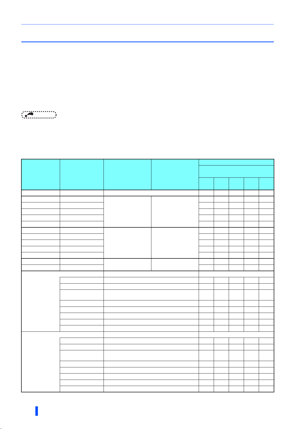
Option lineup for the converter
To use the converter, be sure to use the following options according to the capacity of the converter. Check the model and
quantity of each option. (The abbreviated names are used in this document to facilitate descriptions.)
Quantity
Converter capacity
Option model Component model Name Abbreviation
07700
(15K)
FR-A8VPB-H FR-A8VPB-H Phase detection transformer box 11111
FR-A8BL1-H315K FR-A8BL1-H315K
FR-A8BL1-H355K FR-A8BL1-H355K — 1 — — —
FR-A8BL1-H400K FR-A8BL1-H400K — — 1 — —
FR-A8BL1-H450KFR-A8BL1-H450K ———1 —
FR-A8BL1-H500KFR-A8BL1-H500K ————1
FR-A8BL2-H315K FR-A8BL2-H315K
FR-A8BL2-H355K FR-A8BL2-H355K — 1 — — —
FR-A8BL2-H400K FR-A8BL2-H400K — — 1 — —
FR-A8BL2-H450KFR-A8BL2-H450K ———1 —
FR-A8BL2-H500KFR-A8BL2-H500K ————1
FR-A8BC-H400K FR-A8BC-H400K
FR-A8BC-H500KFR-A8BC-H500K ———1 1
BKO-CA2573H01 Inrush current limit resistor (without thermostat) 3 3 — — —
BKO-CA2573H11 Inrush current limit resistor (with thermostat) 3 3 — — —
BKO-CA2571H01
FR-A8MC-H355K
FR-A8MC-H500K
S-N400 AC200V 2A2B Inrush current limit magnetic contactor 3 3 — — —
SR-T5 AC200V 5A Buffer relay 1 1 — — —
MYQ4Z AC200/220 Mini relay 1 1 — — —
PYF14T Mini relay terminal block 1 1 — — —
PYC-A1 Mini relay clip 2 2 — — —
BKO-CA2573H01 Inrush current limit resistor (without thermostat) — — 6 6 6
BKO-CA2573H11 Inrush current limit resistor (with thermostat) — — 3 3 3
BKO-CA2571H01
S-N400 AC200V 2A2B Inrush current limit magnetic contactor — — 3 3 3
SR-T5 AC200V 5A Buffer relay — — 1 1 1
MYQ4Z AC200/220 Mini relay — — 1 1 1
PYF14T Mini relay terminal block — — 1 1 1
PYC-A1 Mini relay clip — — 2 2 2
Dedicated filter reactor Reactor 1
Dedicated reactor for
PWM control
Dedicated filter capacitor Filter capacitor
Dedicated circuit parts for inrush current protection —
Stepdown transformer for power source of magnetic
contactor (400 to 220 V)
Dedicated circuit parts for inrush current protection —
Stepdown transformer for power source of magnetic
contactor (400 to 220 V)
Reactor 2
1 ————
1 ————
111——
1 1 ———
——111
(FR-A842-[])
08660
(355K)
09620
(400K)
10940
(450K)
12120
(500K)
8
OUTLINE
Page 10
Pre-operation instructions
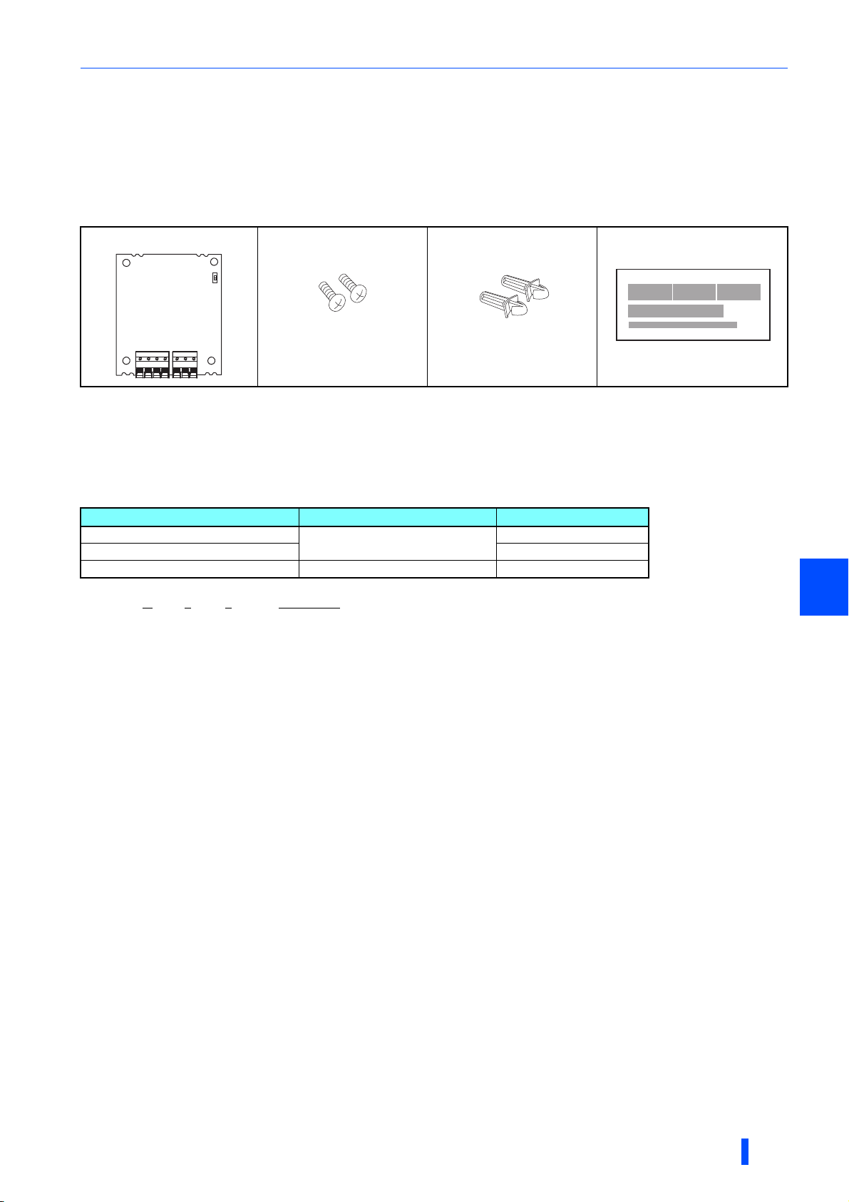
1.1.1 Unpacking and checking the product
Take the product out of the package, check the product name, and confirm that the product is as you ordered and intact.
The FR-A8AVP is a plug-in option for the FR-A802 inverters (separated converter type).
Product confirmation
Check the enclosed items.
Plug-in option: 1
Not used.
Mounting screw (M3 × 8 mm): 2
page 11
(Refer to
.)
SERIAL (serial number) check
The inverter/converter switching function is available for the inverter/converter which satisfies both of the following conditions.
• The inverter has two rating plates: one for the inverter, and the other for the high power factor converter.
• The inverter/converter has the following SERIAL (printed on the rating plate and the package).
Applicable model Country of origin indication SERIAL
FR-A842-12120(500K)
FR-A842-07700(315K) to 10940(450K) 86 or later
FR-A842-07700(315K) to 12120(500K) MADE in China 87 or later
7 Z
Symbol Year Month Control number
The SERIAL consists of one symbol, two characters indicating the production year and month, and six characters indicating the control number.
The last digit of the production year is indicated as the Year, and the Month is indicated by 1 to 9, X (October), Y (November), or Z (December).
MADE in Japan
Spacer
(Refer to
:
2
page 11
.)
7Z or later
• Converter sticker sheet: 1
(Refer to page 16 and page 187.)
R4/L14 S4/L24 T4/L34
CONVERTER
C172D692HXX
∗1
1
OUTLINE
9
Page 11
Pre-operation instructions
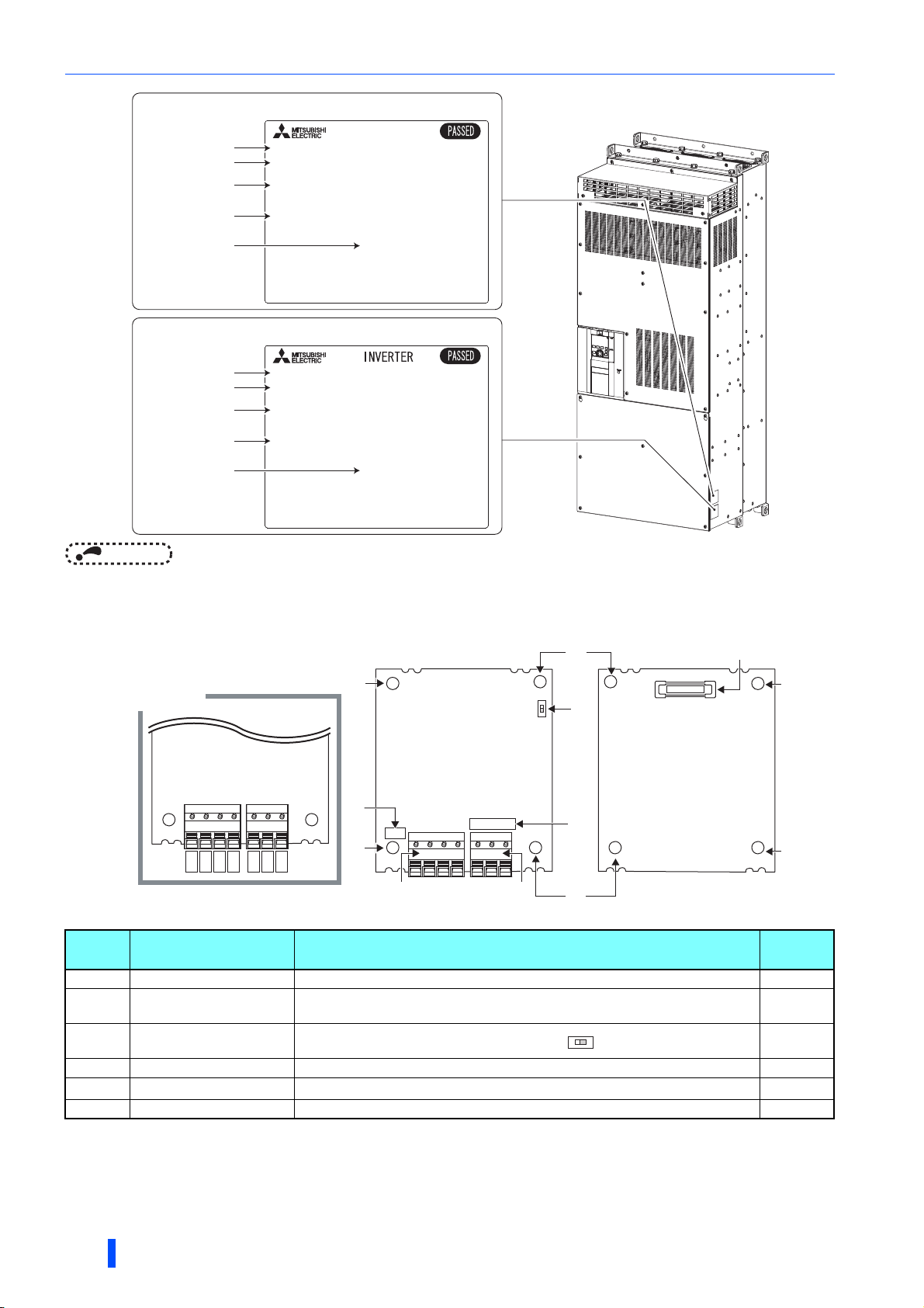
Rating plate (High power factor converter)
Inverter model
Input rating
Output rating
SERIAL
Country of origin
02'(/)5$
,1387;;;;;
287387;;;;;
81,7237,21:25.6$6&219(57(5
6(5,$/;;;;;;;;;
0$'(,1;;;;;
Rating plate (Inverter)
Inverter model
Input rating
Output rating
SERIAL
Country of origin
NOTE
• Ethernet communication is not available when the FR-A802-E inverter has been converted to the high power factor converter.
02'(/)5$
,1387;;;;;
287387;;;;;
6(5,$/;;;;;;;;;
0$'(,1;;;;;
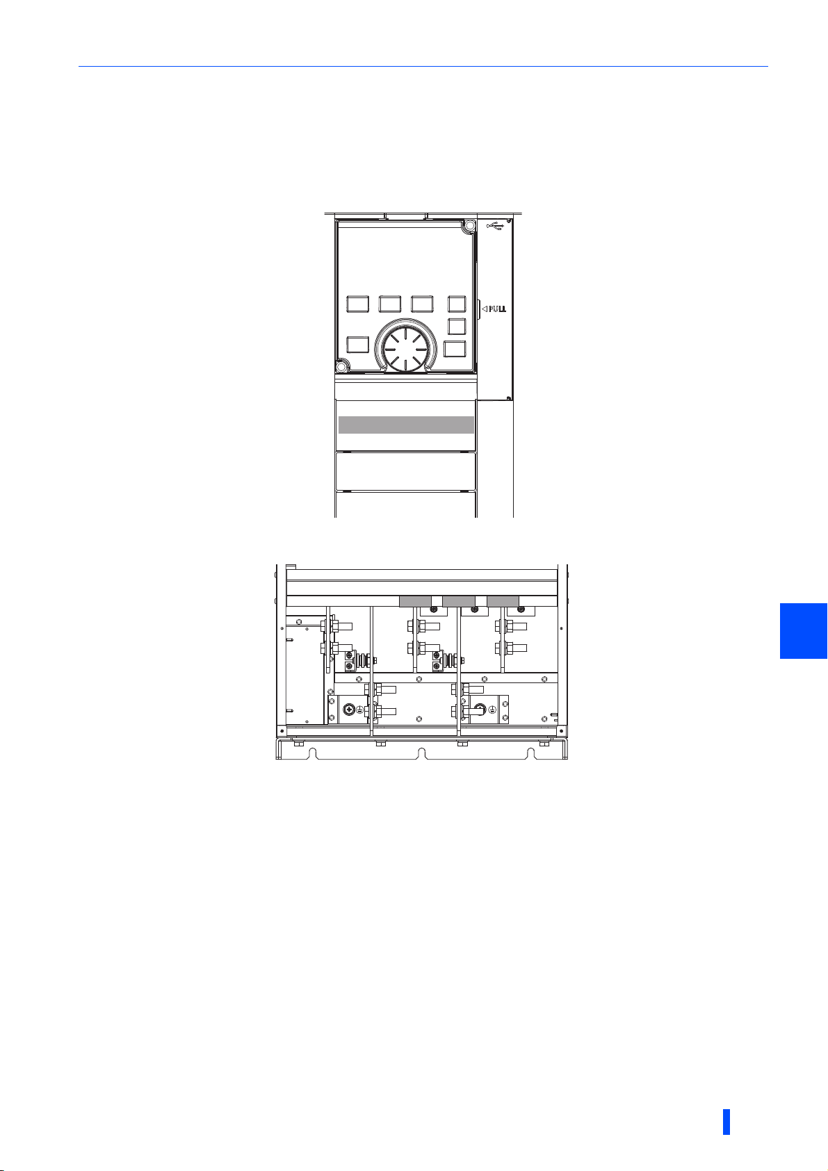
1.1.2 Component names
(a) (d)
SW1
(c)
(e)
(a)
Terminal layout
R2
RS2
S2
T
T2
SE2
Front view
(a)
(f)
Ver.
(a)
RYA
RSO
(b)
SERIAL
(b)
Symbol Name Description
a Mounting hole Fix the option to the inverter (converter) with the screws, or insert spacers. 11
b Terminal block
c
d Connector Connected to the option connector of the inverter (converter). 11
e
f Version information The product version of the FR-A8AVP is printed. —
Switch (SW1) for
manufacturer setting
SERIAL (serial number) The SERIAL of the FR-A8AVP is printed. —
Used to connect the converter (converted from the inverter) to the phase detection
transformer box and to an inverter.
Do not change from the initially-set status (OFF: ).
O
N
Rear view
(a)
(a)
Refer to
page
49
—
10
OUTLINE
Page 12
Pre-installation instructions for the FR-A8AVP
1.2 Pre-installation instructions for the FR-
A8AVP
Check that the inverter's input power and the control circuit power are both OFF.
CAUTION
Do not install or remove the FR-A8AVP while the inverter power is ON. Doing so may damage the
inverter or plug-in option.
To avoid damage due to static electricity, static electricity in your body must be discharged before
you touch the product.
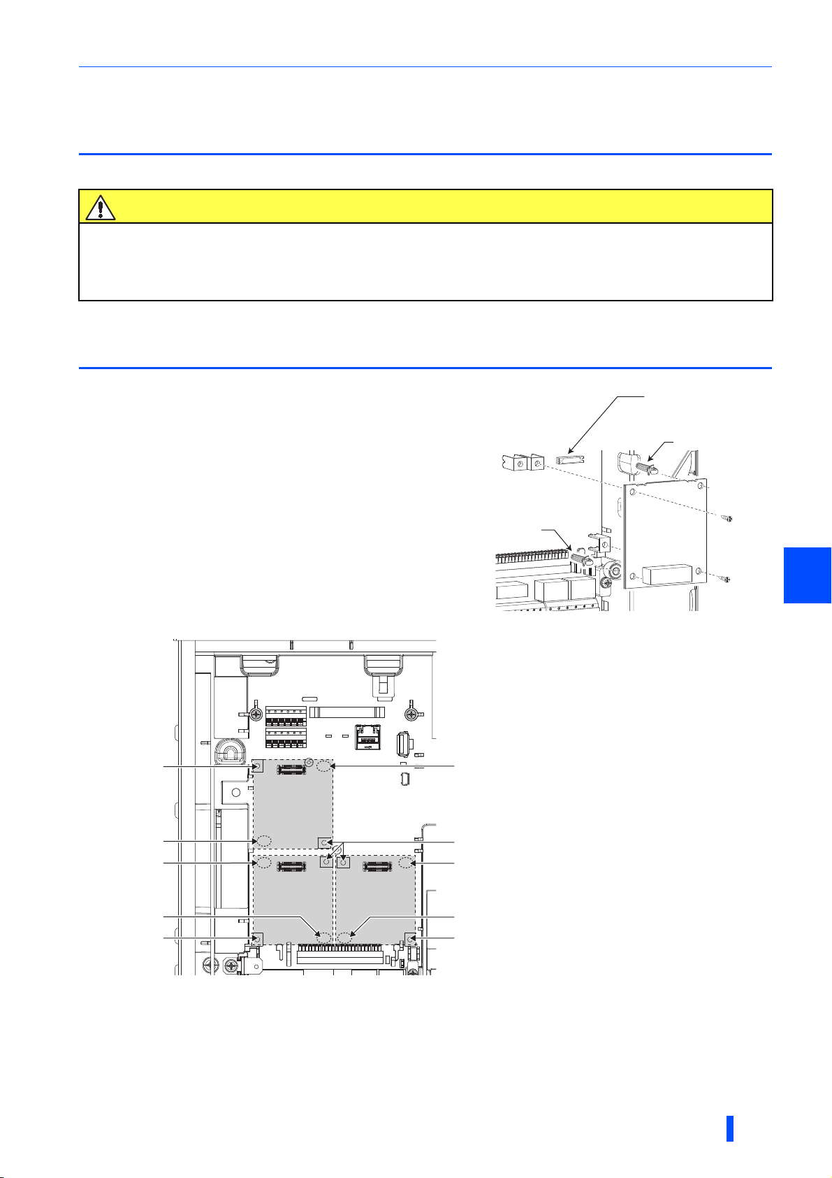
1.3 Installing the FR-A8AVP
(1) Remove the inverter front cover.
(2) Insert spacers into the two mounting holes that will not be tightened
with the option mounting screws (see the following figure).
(3) Fit the connector of the FR-A8AVP to the guide of the connector of
the inverter, and insert the option as far as it goes.
(4) Fasten the FR-A8AVP onto the inverter by fastening the mounting
screws into the holes on the both sides (tightening torque: 0.33 to
0.40 N·m). If the connector is not inserted deep enough, the screws
cannot be tightened properly. Check the connector.
Mounting screw
Spacer
Inverter option connector
Spacer
Spacer
1
Example of installation to connector 1
Spacer
Spacer
Spacer
Mounting screw
The option connector 2 on the FR-A800-E inverters (separated converter type) is not available for use because it is occupied by the Ethernet
Connector 3
Mounting screw
Spacer
Connector 2
Insertion positions for screws and spacers
board which is pre-installed in the initial status. To install the FR-A8AVP to the option connector 2, remove the Ethernet board.
∗1
Connector 1
Spacer
Mounting screw
OUTLINE
11
Page 13
Installing the FR-A8AVP
NOTE
• When installing/removing an option, hold the sides of the circuit board. Do not press on the parts on the circuit board. Stress
applied to the parts by pressing, etc. may cause a failure.
• Take caution not to drop screws during installation and removal of the option.
• Two or more of the same plug-in options cannot be connected. When multiple options are installed, priority is given to option
connectors 1, 2 and 3 on the inverter in this order, and options having a lower priority do not function.
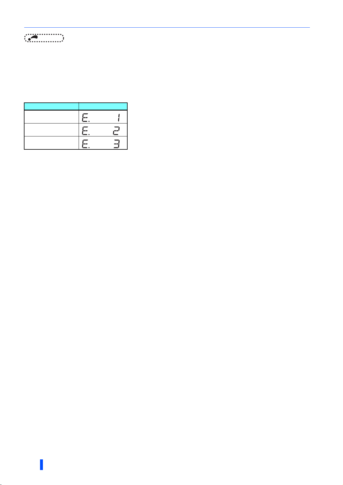
• When the inverter cannot recognize the FR-A8AVP due to improper installation or any other reason, the protective function
(E.1 to E.3) is activated and the inverter cannot be operated. The indication to be shown depends on the position (option
connector 1 to 3) used.
Mounted position Fault indication
Option connector 1
Option connector 2
Option connector 3
• When removing the plug-in option, remove the two screws on the left and right, then pull it straight out. Pressure applied to
the connector and to the option board may break the option.
12
OUTLINE
Page 14

2 INVERTER-TO-
CONVERTER
CONVERSION
This chapter explains how to convert the inverter into a high power factor
converter.
Always read the instructions before use.
2.1 Conversion flowchart ...............................................................14
2.2 Conversion procedure..............................................................15
2.3 Troubleshooting........................................................................18
2
INVERTER-TO-CONVERTER CONVERSION
13
Page 15
Conversion flowchart
Conversion procedure
p
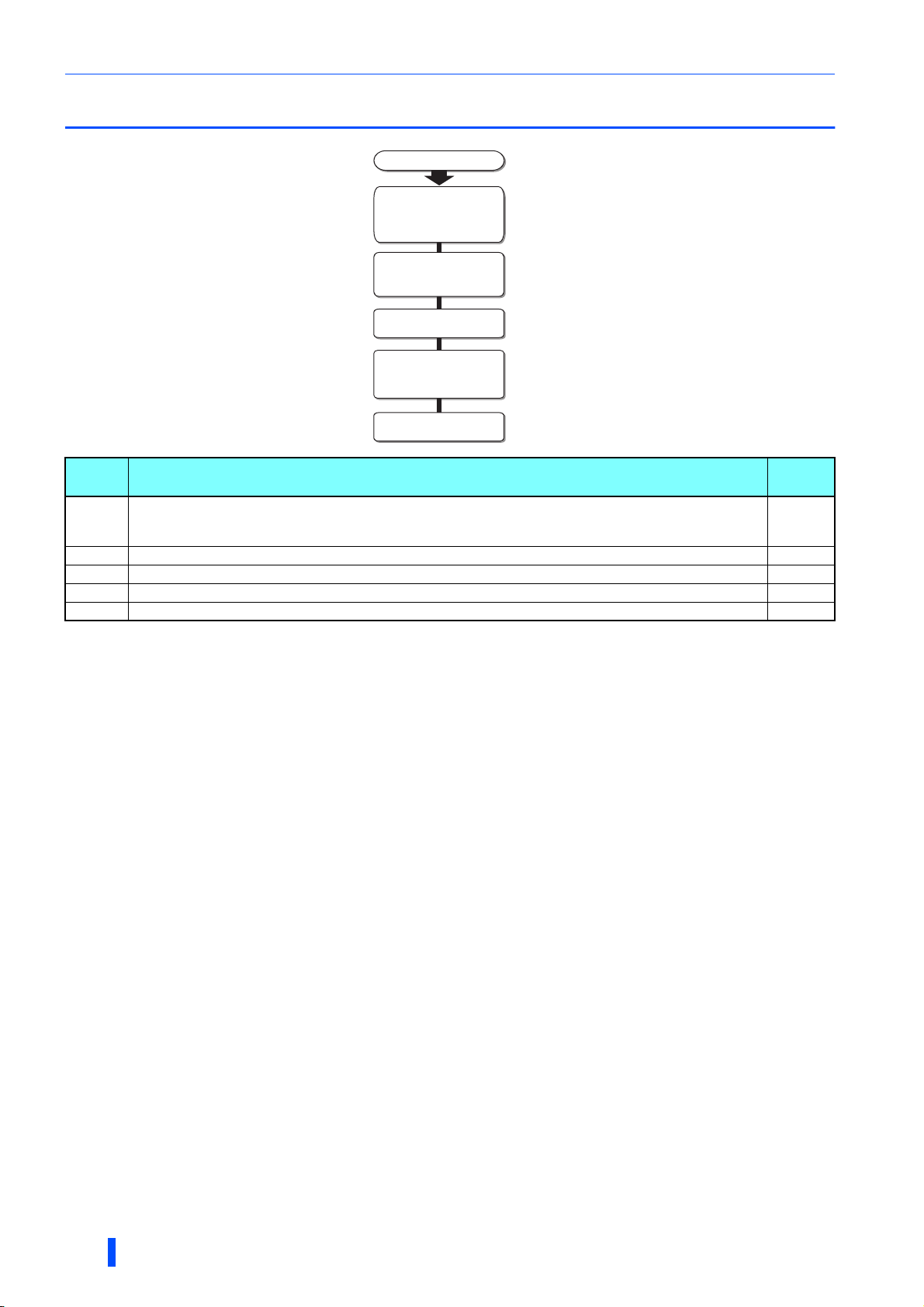
2.1 Conversion flowchart
Conversion procedure
(main circuit: power-OFF,
control circuit: power-ON)
(Pr.328 setting change)
Control circuit: power-OFF
Wiring to other devices
(inverter and converter
Main circuit: power-ON
Symbol Description
Preparation for the inverter-to-converter conversion.
(a)
(b) Change the setting of Pr.328 in the inverter to convert the inverter into a high power factor converter. 16
(c) Turn OFF the control circuit power. 16
(d) Connect an inverter and the converter options to the converter. 40
(e) After the wiring is completed, turn ON the main circuit power of the converter. —
Be sure to turn OFF the main circuit power of the inverter, and turn ON the control circuit power of the inverter
(supplied via terminals R1/L11 and S1/L21 from a separate power source).
n
Preparation
Conversion
options)
(a)
(b)
(c)
(d)
(e)
Refer to
15
page
14
INVERTER-TO-CONVERTER CONVERSION
Page 16

Conversion procedure
2.2 Conversion procedure
This section explains the procedure to convert the inverter to the high factor converter.
2.2.1 Preparation for the conversion
Before starting the conversion, check the following conditions of the inverter (all the conditions must be satisfied).
Check the following while the control circuit power of the inverter is OFF.
• The FR-A8AVP is installed in one of the option connectors (1 to 3). (Refer to page 11.)
• All of the main circuit terminals are left open.
• Terminals R1/L11 and S1/L21 are used to supply power to the control circuit of the inverter.
• No USB memory device is connected.
Check the following while the control circuit power of the inverter is ON.
• The inverter is in the PU operation mode (not in the External/PU combined operation mode 1 or 2).
• The PLC function is disabled (Pr.414 = "0").
• The inverter is in normal state and its operation is stopped (its output is shut off). (No protective function is activated.)
NOTE
• When terminal +24 is used to supply power to the control circuit of the inverter, the conversion to the converter is disabled.
• Sequence programs stored in the inverter for the PLC function will be cleared after the conversion. Be sure to back up the
programs before conversion.
2
INVERTER-TO-CONVERTER CONVERSION
15
Page 17
Conversion procedure
r
2.2.2 Inverter-to-converter conversion (Pr.328)
Pr. Name Initial value
328
E310
Inverter/converter
switching
— 0 to 9999
Setting
range
Description
Change the setting of this parameter according to the
predetermined inverter-to-converter conversion
procedure.
Inverter-to-converter conversion procedure
The following shows the setting procedure for the inverter-to-converter conversion.
Enter the following values in Pr.328 in the following order. If the procedure from step 1 to step 3 is not followed, the parameter
setting will be cleared (the Pr.328 setting returns to its initial value "0"). In that case, restart the procedure from step 1.
1
Enter "3100".
Check that "3100" is displayed for Pr.328.
2
Enter "5010".
Check that "5010" is displayed for Pr.328.
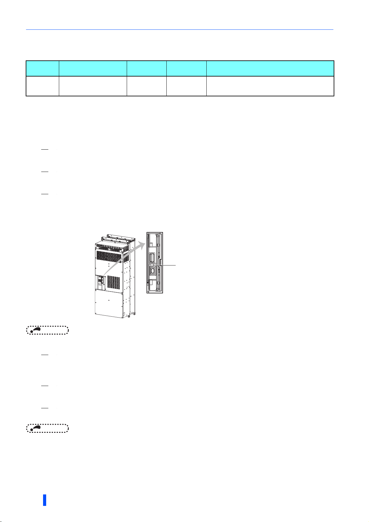
3
Enter "1000".
The inverter-to-converter conversion starts when "1000" is entered. The communication status LED indicator
starts blinking. (The following figure shows the location of the LED indicator.)
The LED indicator stays ON after the conversion is completed.
(It takes about 300 seconds to complete the conversion.)
Communication status LED indicato
NOTE
• After entering "1000", do not operate the PU until the LED indicator stays ON.
4
Reset the control circuit power.
After the reset, "9999" will be displayed for Pr.328.
Functions as an inverter will not be available after this point.
5
After checking that "9999" is displayed for Pr.328, enter "1".
Inverter reset and All parameter clear will start automatically. After the reset, converter functions are available.
6
Press the setting dial on the operation panel (FR-DU08) and check that "CNV" (converter) is
displayed.
NOTE
• If the control circuit power is turned OFF once and then turned ON again, conversion may restart depending on the timing of
power OFF.
16
INVERTER-TO-CONVERTER CONVERSION
Page 18
Conversion procedure
2.2.3 Application of stickers supplied with the
product
Attach the "CONVERTER" sticker and the main circuit terminal stickers ("R4/L14", "S4/L24", and "T4/L34" stickers) supplied
with the FR-A8AVP for indication of the converter.
• Attach the "CONVERTER" sticker to the front cover of the converter as shown in the following figure.
CONVERTER
• Check that the power of the converter is OFF and open the terminal block cover. Attach the main circuit terminal stickers
over the existing "U", "V", and "W" stickers as shown in the following figure.
R4/L14
T4/L34S4/L24
2
INVERTER-TO-CONVERTER CONVERSION
17
Page 19

Troubleshooting
2.3 Troubleshooting
Condition Possible cause Countermeasure
Pr.328 cannot be overwritten.
The Pr.328 setting returns to "0 (initial
value)".
The communication status LED will not
change from blinking to constantly lit.
Checking of the current state (inverter or
converter) is required.
"11" is displayed for Pr.328 after the
conversion.
Preparation for the conversion has not been
completed.
The procedure from step 1 to step 3 was not
followed properly.
The inverter is in the process of the
conversion (the conversion takes 300
seconds after Pr.328 has been set to
"1000").
—
— Please contact your sales representative.
Complete the preparation.
(Refer to page 15.)
Follow the procedure from step 1 to step 3
properly.
(Refer to page 16.)
Contact your sales representative if the
communication status LED indicator remains
blinking (does not become solid) even after a
lapse of 300 seconds.
• Press the setting dial on the operation
panel (FR-DU08) and check the indication.
(Refer to page 16.)
• Check the Pr.328 setting. (Refer to page
16.)
18
INVERTER-TO-CONVERTER CONVERSION
Page 20

3 INSTALLATION AND
WIRING
This chapter explains the installation and the wiring of the converter.
Always read the instructions before use.
3.1 Peripheral devices ....................................................................20
3.2 Selection of breaker, magnetic contactor, and fuse ..............21
3.3 Compatible inverter for the high power factor converter .....22
3.4 Installation of the converter and enclosure design...............24
3.5 Installation of stand-alone options for converter ..................29
3.6 Main circuit terminal specification ..........................................37
3.7 Wiring of main circuit ...............................................................40
3.8 Earthing (Grounding) precautions ..........................................47
3.9 Wiring of control circuit ...........................................................49
3.10 Communication connectors and terminals ............................61
3.11 Connection of the converter and multiple inverters..............64
3
INSTALLATION AND WIRING
19
Page 21
Peripheral devices
(Refer to page 8 and 29.)
(Refer to page 8 and 33.)
(Refer to page 21.)
(Refer to page 8 and 29.)
(Refer to page 53.)
page 22
(Refer to page 8 and 30.)
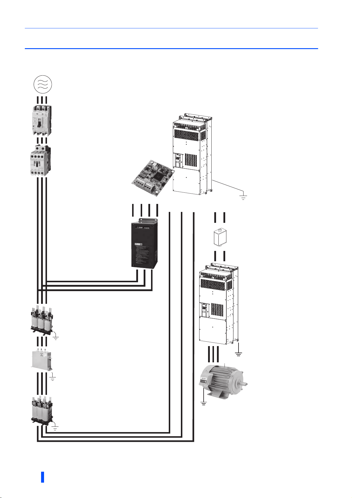
3.1 Peripheral devices
3.1.1 Converter and peripheral devices
Three-phase AC power supply
Use within the permissible power
supply specifications of the converter.
Molded case circuit breaker
(MCCB), earth leakage circuit
breaker (ELB), or fuse
The breaker must be selected
carefully since an inrush current flows
in the converter at power ON.
Magnetic contactor (MC)
Install the MC to ensure safety.
Do not use this MC to start and stop the
converter and the inverter. Doing so will
shorten the life of the inverter and the
converter.
Plug-in option (FR-A8AVP)
Connect the option with the phase
detection transformer box.
R2 RS2 TS2 T2
R4/L14 S4/L24 T4/L34
Converter
Install and wire correctly.
Do not install a molded case circuit
breaker (MCCB) on the main circuit
cables between the inverter and the
converter (terminals P to P and
terminals N to N).
P/+ N/-
Phase detection transformer box
(FR-A8VPB)
Check that its capacity is appropriate
for the capacity of the converter.
Reactor 1 (FR-A8BL1)
Check that its capacity is appropriate
for the capacity of the converter.
Filter capacitor (FR-A8BC) and
dedicated circuit parts for inrush
current protection (FR-A8MC)
Check that their capacity is appropriate
for the capacity of the converter.
Fuse
Install the MC to ensure safety.
Select a fuse according to the
connected motor capacity.
Inverter
Check that the inverter is
compatible with the high power
factor converter. (Refer to
for compatible inverter.)
Select an inverter according to the
capacity of the converter.
The control logic (sink logic/source
logic) of the converter and the
inverter must be matched.
Motor
Install the appropriate capacity
motor according to the capacities
of inverter, converter, etc.
20
Reactor 2 (FR-A8BL2)
Check that its capacity is appropriate
for the capacity of the converter.
INSTALLATION AND WIRING
Earth
(ground)
Devices on the inverter's output side
Do not install a power factor correction
capacitor or surge suppressor on the inverter's
output side.
When installing a molded case circuit breaker
on the output side of the inverter, contact the
manufacturer of the molded case circuit
breaker.
Earth (ground)
Always earth (ground) the converter, converter
options, inverter, and motor.
Page 22
Selection of breaker, magnetic contactor, and fuse
3.2 Selection of breaker, magnetic contactor,
and fuse
Circuit breakers and magnetic contactors
Check the model of the converter. The correct breaker and magnetic contactor must be installed with the appropriate
converter capacity.
Refer to the following table to select the appropriate breaker and magnetic contactor.
High power factor
converter model
FR-A842-07700(315K) 700 A S-N600
FR-A842-08660(355K) 800 A S-N600
FR-A842-09620(400K) 900 A S-N800
FR-A842-10940(450K) 1000 A S-N400 (3 in parallel)
FR-A842-12120(500K) 1200 A S-N400 (3 in parallel)
Molded case circuit breaker (MCCB)
or earth leakage circuit breaker (NF, NV type)
Magnetic contactor
(MC)
Select an MCCB according to the power supply capacity.
Install one MCCB per converter.
(For the use in the United States or Canada, refer to page 194, and select the
appropriate fuse.)
The magnetic contactor is selected based on the AC-1 class. The electrical durability of magnetic contactor is 500,000 times. When the
magnetic contactor is used for emergency stops during motor driving, the electrical durability is 25 times.
If using an MC for emergency stop during motor driving or using it on the motor side during commercial power supply operation, select an MC
with the class AC-3 rated current for the rated motor current.
MCCB
MCCB
Converter
Converter
Inverter
Inverter
IM
IM
NOTE
• When the breaker installed at the converter's input line is shut off, check for the wiring fault (short circuit), damage to internal
parts of the converter, etc. The cause of the trip must be identified and removed before turning ON the power of the breaker.
Fuse
Installation of a fuse is recommended between the converter and an inverter. Select a fuse according to the capacity of the
connected motor. When using a motor, of which the capacity is smaller than the inverter capacity by two ranks or more, select
the fuse with the capacity that is one rank lower than the inverter capacity. (For the details, refer to page 45.)
• Fuse selection table
Motor capacity (kW) Fuse rating (A) Model
315 1600
355 1800
400 1800
450 2500 6.9 URD 33 TTF 1250 × 2 (parallel connection)
500 2700 6.9 URD 32 TTF 0900 × 3 (parallel connection)
Manufacturer: Mersen Japan KK
Contact: Sun-Wa Technos Corporation
When installing several fuses in parallel, leave a space of 12 mm or more between the fuses.
6.9 URD 232 TDF 1600 or
6.9 URD 31 TTF 0800 × 2 (parallel connection)
6.9 URD 232 TDF 1800 or
6.9 URD 32 TTF 0900 × 2 (parallel connection)
6.9 URD 232 TDF 1800 or
6.9 URD 32 TTF 0900 × 2 (parallel connection)
3
NOTE
• Install fuses across terminals P/+ and P/+, and across terminals N/- and N/- of the converter and an inverter.
• Fuses are not required when the converter is used in combination with a FR-A842-07700(315K) to 12120(500K) inverter,
which has internal fuses.
• Estimated lifespan of fuses
Components
Fuse 10 years Replace by new one
Estimated lifespan for when the yearly average surrounding air temperature is 50°C (without corrosive gas, flammable gas, oil mist, dust and dirt etc.).
Estimated
lifespan
Replacement method
NOTE
• If the fuse melts down, wiring failure such as a short circuit may be the cause. Find out the cause and remove it before replacing the fuse.
INSTALLATION AND WIRING
21
Page 23

Compatible inverter for the high power factor converter
5
3.3 Compatible inverter for the high power
factor converter
3.3.1 Applicable inverter capacity
The required converter capacity differs by the multiple rating selection setting of the inverter.
Refer to the following table for the connectable inverter capacities when connecting one inverter to a high power factor
converter. (The combination with the inverter not specified in the table is not applicable.)
: Applicable.
-: Usable as a common converter or regenerative converter, but the harmonic suppression effect decreases.
: Not applicable.
NOTE
• For details of the inverter capacity, refer to the rating specifications in the Instruction Manual of the inverter.
Example: FR-A820
Model FR-A820-[]
00046 00077 0010
0.4K 0.75K 1.5K
2.25.157.0DLS
When the inverter capacity and the applicable motor capacity are equal
(FR-A800 (ND rating), FR-F800 (LD rating), and 700 series inverters)
Inverter capacity
Converter capacity
FR-A842-07700(315K) - -
FR-A842-08660(355K) - -
FR-A842-09620(400K) - - -
FR-A842-10940(450K) - - - -
FR-A842-12120(500K) - - - -
132K
or
lower
160K 185K 220K 250K 280K 315K 355K 375K 400K 450K 500K 530K 560K
When the applicable motor capacity is higher than the inverter capacity
(FR-A800 (LD rating), FR-A800 (SLD rating), and FR-F800 (SLD rating))
Refer to the table above to check the applicability of the converter. When the capacity of a motor to be installed is larger than
the converter capacity, read the "inverter capacity" in the table above as the applicable "motor capacity".
When the applicable motor capacity is lower than the inverter capacity
(FR-A800 (HD rating))
Inverter capacity
Converter capacity
FR-A842-07700(315K) - -
FR-A842-08660(355K) - -
FR-A842-09620(400K) - - -
FR-A842-10940(450K) - - - -
FR-A842-12120(500K) - - - -
132K
or
lower
160K 185K 220K 250K 280K 315K 355K 400K 450K 500K 560K
22
INSTALLATION AND WIRING
Page 24

Compatible inverter for the high power factor converter
3.3.2 Inverter parameter settings
When using the converter with the inverter, some inverter parameters must be set. The parameter settings differ by the
inverter series. The parameter settings differ by the inverter series.
For the parameters and inverters not listed below, refer to the Instruction Manual of the inverter.
Inverter series
FR-A800, FR-F800 2, 102
FR-E700, FR-F700PJ,
FR-D700
Pr.30 Regenerative function
0 (initial value),
2 (when the automatic restart after
instantaneous power failure
function is enabled)
selection
V/F control Other than V/F control
Pr.19 Base frequency voltage Pr.83 Rated motor voltage
Rated motor voltage
3
INSTALLATION AND WIRING
23
Page 25
Installation of the converter and enclosure design
3.4 Installation of the converter and enclosure
design
When designing or manufacturing an enclosure, determine the structure, size, and device layout by fully considering the
conditions such as heat generation of the contained devices and the operating environment. The converter uses many
semiconductor devices. To increase reliability and prolong the life of the product, operate the converter in an environment that
sufficiently satisfies the standard environmental specifications.
3.4.1 Converter installation environment
The following table lists the standard specifications of the converter installation environment. Using the converter in an
environment that does not satisfy the conditions deteriorates the performance, shortens the life, and causes a failure. Refer to
the following points, and take adequate measures.
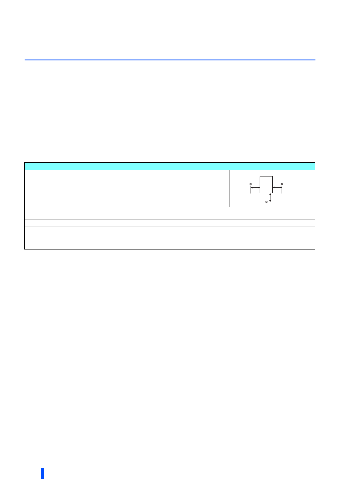
Standard environmental specifications of the converter
Item Description
Measurement
position
Converter
Surrounding air
temperature
Surrounding air
humidity
Storage temperature -20 to +65°C
Atmosphere Indoors (free from corrosive gas, flammable gas, oil mist, dust and dirt)
Altitude 2500 m or lower
Vibration
Temperature applicable for a short time, for example, in transit.
For the installation at an altitude above 1000 m, consider a 3% reduction in the rated current per 500 m increase in altitude.
-10 to +50°C (non-freezing)
With circuit board coating: 95% RH or less (non-condensing)
Without circuit board coating: 90% RH or less (non-condensing)
2
2.9 m/s
or less at 10 to 55 Hz (directions of X, Y, Z axes)
5 cm
Measurement
position
5 cm
5 cm
Temperat ure
The permissible surrounding air temperature of the converter is between -10 and +50°C. Always operate the converter within
this temperature range. Operation outside this range will considerably shorten the service lives of the semiconductors, parts,
capacitors and others. Take the following measures to keep the surrounding air temperature of the converter within the
specified range.
(a) Measures against high temperature
• Use a forced ventilation system or similar cooling system. (Refer to page 26.)
• Install the enclosure in an air-conditioned electric chamber.
• Block direct sunlight.
• Provide a shield or similar plate to avoid direct exposure to the radiated heat and wind of a heat source.
• Ventilate the area around the enclosure well.
(b) Measures against low temperature
• Provide a space heater in the enclosure.
• Do not power OFF the converter. (Keep the start signal of the inverter OFF.)
(c) Sudden temperature changes
• Select an installation place where temperature does not change suddenly.
• Avoid installing the converter near the air outlet of an air conditioner.
• If temperature changes are caused by opening/closing of a door, install the converter away from the door.
Humidity
Operate the converter within the ambient air humidity range of 45 to 90% (up to 95% with circuit board coating). Too high
humidity will pose problems of reduced insulation and metal corrosion. On the other hand, too low humidity may cause a
spatial electrical breakdown. The humidity conditions for the insulation distance defined in JEM 1103 standard "Insulation
Distance from Control Equipment" is 45 to 85%.
24
INSTALLATION AND WIRING
Page 26

Installation of the converter and enclosure design
(a) Measures against high humidity
• Make the enclosure enclosed, and provide it with a hygroscopic agent.
• Provide dry air into the enclosure from outside.
• Provide a space heater in the enclosure.
(b) Measures against low humidity
Air with proper humidity can be blown into the enclosure from outside. Also when installing or inspecting the unit, discharge
your body (static electricity) beforehand, and keep your body away from the parts and patterns.
(c) Measures against condensation
Condensation may occur if frequent operation stops change the in-enclosure temperature suddenly or if the outside air
temperature changes suddenly.
Condensation causes such faults as reduced insulation and corrosion.
• Take the measures against high humidity in (a).
• Do not power OFF the converter. (Keep the start signal of the inverter OFF.)
Dust, dirt, oil mist
Dust and dirt will cause such faults as poor contacts, reduced insulation and cooling effect due to the moisture-absorbed
accumulated dust and dirt, and in-enclosure temperature rise due to a clogged filter. In an atmosphere where conductive
powder floats, dust and dirt will cause such faults as malfunction, deteriorated insulation and short circuit in a short time.
Since oil mist will cause similar conditions, it is necessary to take adequate measures.
Countermeasure
• Place the converter in a totally enclosed enclosure.
Take measures if the in-enclosure temperature rises. (Refer to page 26.)
• Purge air.
Pump clean air from outside to make the in-enclosure air pressure higher than the outside air pressure.
Corrosive gas, salt damage
If the converter is exposed to corrosive gas or to salt near a beach, the printed board patterns and parts will corrode or the
relays and switches will result in poor contact.
In such places, take the measures given in the previous paragraph.
Explosive, flammable gases
As the converter is non-explosion proof, it must be contained in an explosion-proof enclosure. In places where explosion may
be caused by explosive gas, dust or dirt, an enclosure cannot be used unless it structurally complies with the guidelines and
has passed the specified tests. This makes the enclosure itself expensive (including the test charges). The best way is to
avoid installation in such places and install the converter in a non-hazardous place.
High altitude
Use the converter at an altitude of within 2500 m. For use at an altitude above 1000 m, consider a 3% reduction in the rated
current per 500 m increase in altitude.
If it is used at a higher place, it is likely that thin air will reduce the cooling effect and low air pressure will deteriorate dielectric
strength.
3
Vibration, impact
The vibration resistance of the converter is up to 2.9 m/s2 at 10 to 55 Hz frequency and 1 mm amplitude for the directions of
X, Y, Z axes. Applying vibration and impacts for a long time may loosen the structures and cause poor contacts of connectors,
even if those vibration and impacts are within the specified values.
Especially when impacts are applied repeatedly, caution must be taken because such impacts may break the installation feet.
Countermeasure
• Provide the enclosure with rubber vibration isolators.
• Strengthen the structure to prevent the enclosure from resonance.
• Install the enclosure away from the sources of the vibration.
INSTALLATION AND WIRING
25
Page 27
Installation of the converter and enclosure design
3.4.2 Cooling system types for converter enclosure
From the enclosure that contains the converter, the heat of the converter and other equipment (inverter, transformers,
reactors, lamps, resistors, etc.) and the incoming heat such as direct sunlight must be dissipated to keep the in-enclosure
temperature lower than the permissible temperatures of the in-enclosure equipment including the converter.
The cooling systems are classified as follows in terms of the cooling calculation method.
(a) Cooling by natural heat dissipation from the enclosure surface (totally enclosed type)
(b) Cooling by heatsink (aluminum fin, etc.)
(c) Cooling by ventilation (forced ventilation type, pipe ventilation type)
(d) Cooling by heat exchanger or cooler (heat pipe, cooler, etc.)
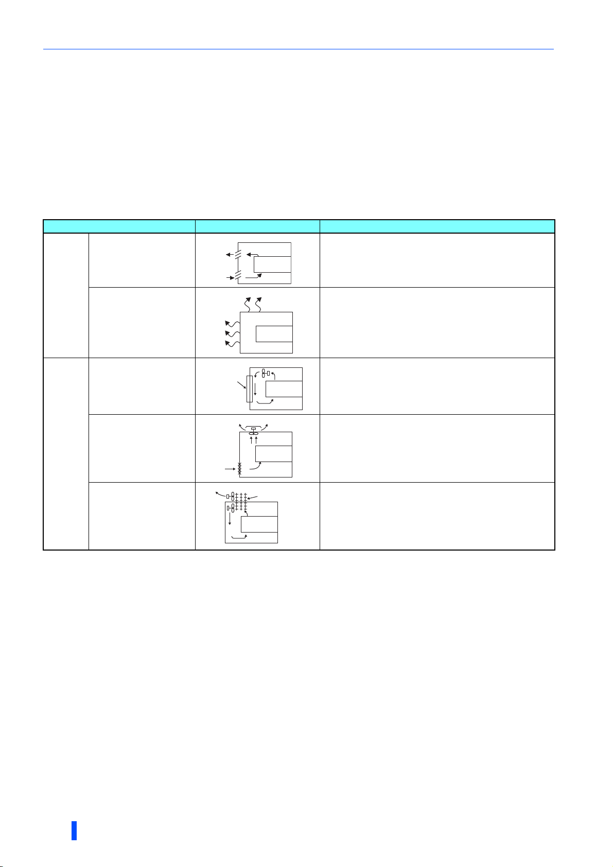
Cooling system Enclosure structure Comment
Natural
Forced air
Natural ventilation
(enclosed type / open type)
Natural ventilation (totally
enclosed type)
Heatsink cooling
Forced ventilation
Heat pipe
Heatsink
Converter
Converter
Converter
Heat pipe
Converter
Converter
This system is low in cost and generally used, but the
enclosure size increases as the converter capacity increases.
This system is for relatively small capacities.
Being a totally enclosed type, this system is the most
appropriate for hostile environment having dust, dirt, oil mist,
etc. The enclosure size increases depending on the converter
capacity.
This system has restrictions on the heatsink mounting position
and area. This system is for relatively small capacities.
This system is for general indoor installation. This is
appropriate for enclosure downsizing and cost reduction, and
often used.
This system is a totally enclosed type, and is appropriate for
enclosure downsizing.
26
INSTALLATION AND WIRING
Page 28
Installation of the converter and enclosure design
Vertical
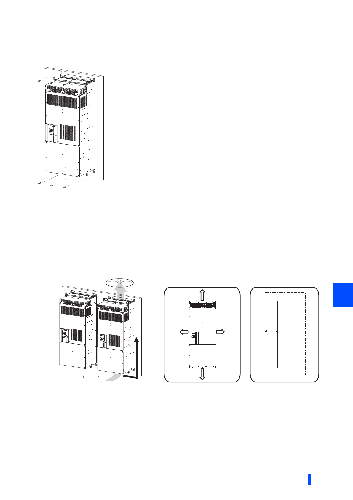
3.4.3 Installation of the converter
Placement of the converter
• Install the converter on a strong surface securely with screws.
• Leave enough clearances and take cooling measures.
• Avoid places where the converter is subjected to direct sunlight, high temperature and high humidity.
• Install the converter on a nonflammable wall surface.
• When encasing multiple converters in an enclosure, install them in parallel as a cooling measure.
• For heat dissipation and maintenance, keep clearance between the converter and the other devices or enclosure surface.
The clearance below the converter is required as a wiring space, and the clearance above the converter is required as a
heat dissipation space.
• When designing or building an enclosure for the converter, carefully consider influencing factors such as heat generation of
the contained devices and the operating environment.
Clearances (side view)Clearances (front view)
20 cm or more
5 cm
or
more
∗1
Converter
Vertical
Vertical
10 cm
or
more
10 cm
or
more
3
Allow clearance.
For replacing the cooling fan, 30 cm of space is necessary in front of the converter. Refer to page 167 for fan replacement.
20 cm or more
Installation orientation of the converter
Install the converter on a wall as specified. Do not mount it horizontally or in any other way.
Above the converter
Heat is blown up from inside the converter by the small fan built in the unit. Any equipment placed above the converter should
be heat resistant.
INSTALLATION AND WIRING
27
Page 29
Installation of the converter and enclosure design
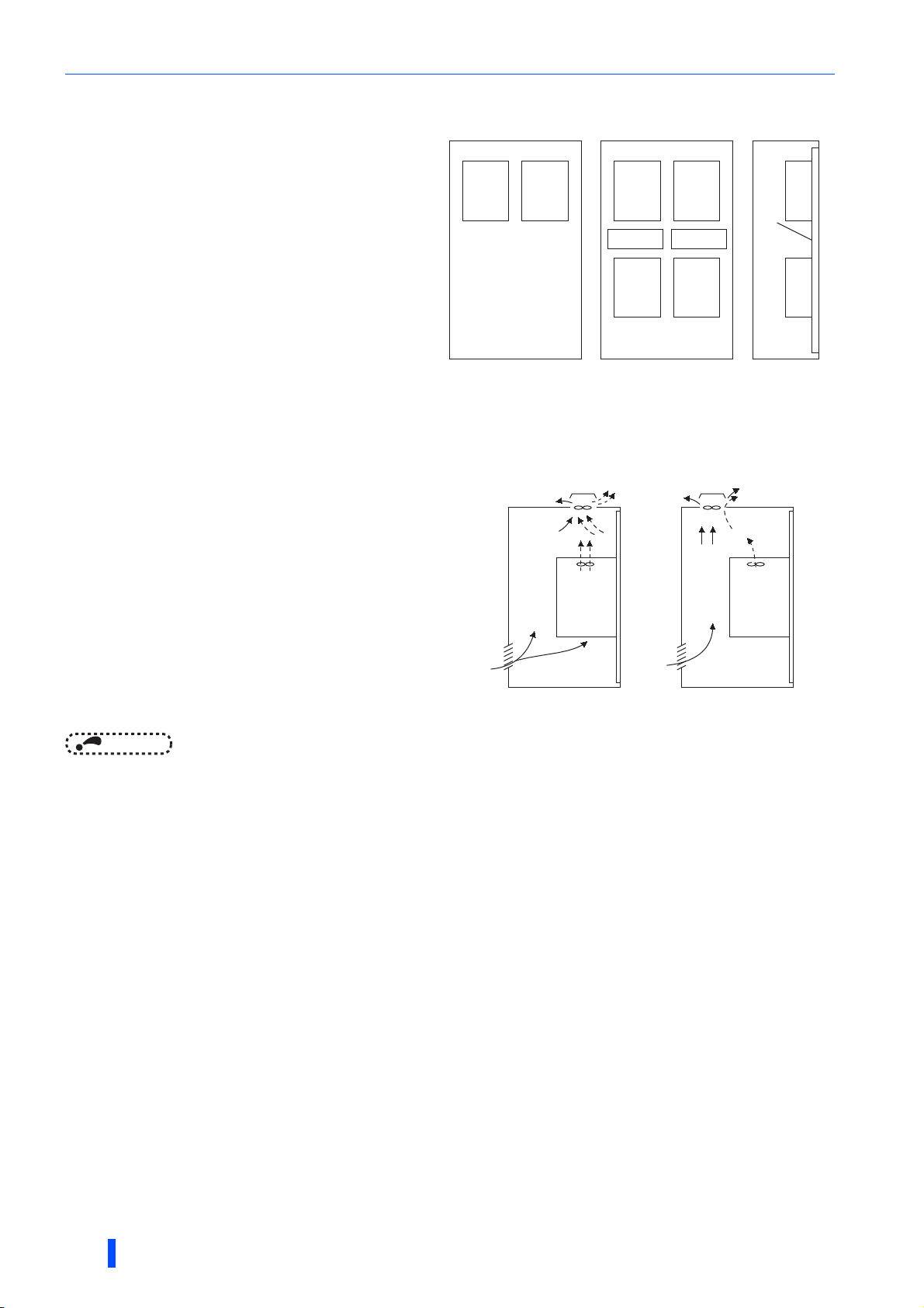
Arrangement of multiple inverters and converters
When multiple inverters and converters are placed in the
same enclosure, generally arrange them horizontally as
shown in the figure (a). When it is inevitable to arrange
them vertically to minimize space as shown in the figure
(b), take such measures as to provide guides since heat
generated in the units in bottom row can increase the
temperatures in the units in top row, causing the failure of
the units in top row.
Converter
Inverter Inverter
Inverter
Guide Guide
Converter
Converter
Guide
When mounting multiple inverters and converters, fully
take caution not to make the surrounding air temperature
of the inverter and the converter higher than the
permissible value by providing ventilation and increasing
the enclosure size.
(a) Horizontal arrangement (b) Vertical arrangement
Enclosure Enclosure
Arrangement of multiple inverters and converters
Placement of the ventilation fan and converter
Heat generated in the converter is blown up from the bottom of
the unit as warm air by the cooling fan. When installing a
ventilation fan for that heat, determine the place of ventilation
fan installation after fully considering an air flow. (Air passes
through areas of low resistance. Make an airway and airflow
plates to expose the converter to cool air.)
<Good example> <Bad example>
Arrangement of the ventilation fan and converter
NOTE
• To remove or reinstall the front cover or the operation panel (FR-DU08) of the converter, refer to the FR-A802 Instruction
Manual (Hardware) as the procedure is the same as that for the inverter.
Converter
Converter
3.4.4 Protruding the heatsink through a panel
When encasing the converter to an enclosure, the heat generated in the enclosure can be greatly reduced by protruding its
heatsink through the rear panel of the enclosure. To protrude the heatsink, refer to the FR-A802 Instruction Manual
(Hardware) as the procedure is the same as that for the inverter.
28
INSTALLATION AND WIRING
Page 30
Installation of stand-alone options for converter
3.5 Installation of stand-alone options for
converter
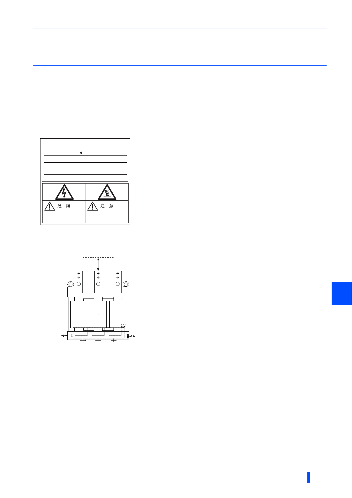
3.5.1 Installation of the reactor 1 (FR-A8BL1) and
reactor 2 (FR-A8BL2)
Model confirmation
Before installing the reactor 1 and reactor 2, check the model on their rating plate (see the following figure) to avoid confusing
them with each other as they look very similar. Refer to page 178 to check the rating plate position.
Rating plate example: Reactor 1 (FR-A8BL1)
AC REACTOR
MODEL
FR-A8BL1-H500K
Model
CAUTIONDANGER
Clearances
As the reactors generate heat, leave sufficient space around them.
5 cm or more
5 cm or more
5 cm or more
Installation place
Install the reactors on nonflammable material. Installing them directly on flammable material will cause a fire.
3
Surrounding environment
Avoid places where the reactors are subjected to oil mist, flammable gases, fluff, dust, dirt, etc.
Choose a clean place for installation, or protect it from suspended substances using a dust filter or the like.
INSTALLATION AND WIRING
29
Page 31

Installation of stand-alone options for converter
Installation orientation
To prevent looseness, install the reactors on a horizontal surface securely with screws or bolts.
Do not install them on a vertical surface. Install them on a mounting stand which can withstand its weight.
NOTE
• As the charged sections of the reactors are uncovered, fully protect them to prevent ground fault and electric shock.
• Intrusion of wire offcuts or dust into the cooling fan of the reactors can cause a failure or malfunction.
Keep clean environment for the reactors.
3.5.2 Installation of the phase detection transformer
box (FR-A8VPB)
Checking the Phase detection transformer box rating plate
Before installing the transformer box, check the values to be set in Pr.1344 and Pr.1345 described on its rating plate, and take
a note of them. The same values must be set in Pr.1344 and Pr.1345 of the converter. (Refer to page 90.)
Clearances
10 cm or more
5 cm or more
Installation place
5 cm or more
10 cm or more
5 cm or more
Install the transformer box on nonflammable material. Installing it directly on flammable material will cause a fire.
Surrounding environment
Avoid places where the transformer box is subjected to oil mist, flammable gases, fluff, dust, dirt, etc.
Install the transformer box in a clean place or protect it from suspended substances.
30
INSTALLATION AND WIRING
Page 32

Installation of stand-alone options for converter
• Loosen the mounting screws of the cover. • Pull out the cover to remove it.
Installation orientation
Install the transformer box in a vertical position.
Removal and reinstallation of the cover
Removal
Verti ca l
Front cover
Front cover
3
INSTALLATION AND WIRING
31
Page 33

Installation of stand-alone options for converter
• Align the screw holes on the cover with the holes
on the transformer box, and place the cover back
into position.
• Fix the cover with the mounting screw
(tightening torque: 1.7 N·m).
Reinstallation
NOTE
• Fully make sure that the front cover has been reinstalled securely. Always tighten the mounting screws of the cover.
• The capacity plate is placed on the cover, and the rating plate is on the remainder of the transformer box. For reinstallation,
check the serial number on the capacity plate against the one on the rating plate to make sure they are identical with each
other.
Wiring method
Cut small slits in the rubber grommets mounted on the underside of the transformer box, and pass the cables through the slits.
NOTE
• To satisfy IP20 protection requirements, note the following points for wiring of the transformer box.
- Do not cut slits in the rubber grommets which are not used for wiring.
- Do not use the transformer box with the rubber grommets removed.
32
INSTALLATION AND WIRING
Page 34

Installation of stand-alone options for converter
3.5.3 Installation of the filter capacitor (FR-A8BC)
Clearances
As the filter capacitor generates heat, leave sufficient space around them.
10 cm or more
10 cm or more10 cm or more
Installation place
Install the filter capacitor on nonflammable material. Installing it directly on flammable material will cause a fire.
Surrounding environment
Avoid places where the filter capacitor is subjected to oil mist, flammable gases, fluff, dust, dirt, etc.
Install the filter capacitor in a clean place or protect it from suspended substances.
Installation of fixing brackets (FR-A8BC-H400K)
Two fixing brackets come with the FR-A8BC-H400K filter capacitor. Hang the hook of fixing brackets on top of both sides of
the capacitor as shown in the following figure. Fasten the capacitor with screws to a stand through the mounting holes on the
brackets.
Fixing bracket
Mounting hole
Installation orientation
To prevent looseness, install the filter capacitor on a horizontal surface securely with screws or bolts.
Do not install it on a vertical surface. Install it on a mounting stand which can withstand its weight.
3
NOTE
• As the charged sections of the filter capacitor is uncovered, fully protect it to prevent ground fault and electric shock.
INSTALLATION AND WIRING
33
Page 35

Installation of stand-alone options for converter
3.5.4 Installation of the dedicated circuit parts for
inrush current protection (FR-A8MC)
Inrush current limit resistor
Clearances
As the inrush current limit resistor generates heat, leave sufficient space around them.
3 cm or more 3 cm or more
3 cm or more
Installation place
Install the resistor on nonflammable material. Installing directly on or near a flammable material will cause a fire.
Surrounding environment
Avoid places where the resistor is subjected to oil mist, flammable gases, fluff, dust, dirt, etc.
Install the resistor in a clean place or protect it from suspended substances.
Do not place a flammable material near the resistor.
Installation orientation
To prevent looseness, install the resistor on a horizontal or vertical surface securely with screws or bolts.
34
INSTALLATION AND WIRING
Page 36

Installation of stand-alone options for converter
MC power supply stepdown transformer
Clearances
As the stepdown transformer generates heat, leave sufficient space around them.
10 cm or more
10 cm or more 10 cm or more
Installation place
Install the stepdown transformer on nonflammable material. Installing it directly on flammable material will cause a fire.
Surrounding environment
Avoid places where the stepdown transformer is subjected to oil mist, flammable gases, fluff, dust, dirt, etc.
Install the stepdown transformer in a clean place or protect it from suspended substances.
Installation orientation
To prevent looseness, install the stepdown transformer on a horizontal or vertical surface securely with screws or bolts.
NOTE
• As the charged sections of the stepdown transformer is uncovered, fully protect it to prevent ground fault and electric shock.
3
INSTALLATION AND WIRING
35
Page 37

Installation of stand-alone options for converter
3.5.5 Terminals of stand-alone options for the
converter
Reactor 1
Terminal symbol Description
R/L1, S/L2, T/L3 Connected to the commercial power supply.
R2/L12, S2/L22, T2/L32
R5, S5 Connected to the cooling fan power output terminals on the stepdown transformer for power source of MC.
TP1, TP2
Reactor 2
Terminal symbol Description
R3/L13, S3/L23, T3/L33
R4/L14, S4/L24, T4/L34 Connected to the converter.
R5, S5 Connected to the cooling fan power output terminals on the stepdown transformer for power source of MC.
TP3, TP4
Connected to the reactor 2. Between two reactors, the filter capacitor and the dedicated circuit parts for inrush
current protection must be installed.
If reactor 1 overheats, the circuit will open (thermostat output) between TP1 and TP2.
•TP1:
Connected to the converter terminal to which the LOH signal is assigned.
•TP2:
Connected to terminal TP3 of the reactor 2.
Earthing (grounding) of the reactor 1. This must be earthed (grounded).
Connected to the reactor 1. Between two reactors, the filter capacitor and the dedicated circuit parts for inrush
current protection must be installed.
If reactor 2 overheats, the circuit will open (thermostat output) between TP3 and TP4.
•TP3:
Connected to terminal TP2 of the reactor 1.
•TP4:
Connected to terminal SD of the converter.
Earthing (grounding) of the reactor 2. This must be earthed (grounded).
Filter capacitor
Terminal symbol Description
R2/L12, S2/L22, T2/L32 Connected to the output terminals of the reactor 1 and the input terminals of the inrush current limit resistor.
Earthing (grounding) of the filter capacitor. This must be earthed (grounded).
Phase detection transformer box
Terminal symbol Description
R Input terminal for detection of the R-phase voltage of the system power supply.
S Input terminal for detection of the S-phase voltage of the system power supply.
T Input terminal for detection of the T-phase voltage of the system power supply.
R2
RS2 Common terminal for terminal R2. —
T2
TS2 Common terminal for terminal T2. —
Output terminal for the analog signal used for the R-S detection.
Isolated from the main circuit.
Output terminal for the analog signal used for the T-S detection.
Isolated from the main circuit.
Earthing (grounding) of the phase detection transformer box. This must be earthed
(grounded).
Rated
specification
Maximum
permissible input
voltage: 506 VAC
Maximum output
voltage: 26 VAC
Maximum output
voltage: 26 VAC
—
36
INSTALLATION AND WIRING
Page 38

Main circuit terminal specification
3.6 Main circuit terminal specification
3.6.1 Details on the main circuit terminals
Terminal symbol Description Refer to page
R4/L14, S4/L24, T4/L34 Connected to the reactor 2. —
R1/L11, S1/L21
P/+, N/- Connected to the inverter terminals P/+ and N/-. 40
3.6.2 Main circuit terminal block layout
FR-A842-07700(315K) to 12120(500K)
R1/L11 S1/L21
Connected to terminals P/+ and N/- in the initial status. To retain the fault display and
fault output, remove the jumpers and apply external power through these terminals.
For earthing (grounding) of the converter chassis. This must be earthed (grounded). 47
Charge lamp
Jumper
58
To inverter
N/-
P/+
R4/L14
T4/L34
S4/L24
3
To reactor 2
INSTALLATION AND WIRING
37
Page 39

Main circuit terminal specification
3.6.3 Cable size of the main circuit terminals and the
earth (ground) terminal
Select cables of recommended gauge size to ensure that the voltage drop will be 2% or less.
The following table shows a selection example for the wiring length of 20 m.
•Converter
Cable gauge
PVC cables, etc.
(mm2)
R4/L14,
S4/L24,
Earthing
(grounding)
T4/L34
PVC cables, etc.
2
(mm
R/L11,
S/L21,
T/L31,
R2/L12,
S2/L22,
T2/L32
cable
)
Tightening
torque
N·m
Crimp
terminal
HIV cables, etc. (mm2)
R4/L14,
S4/L24,
T4/L34
P/+, N/-
Earthing
(grounding)
cable
Model
FR-A842-[]
07700(315K) M12 (M10) 46 (24) 150-12 2 × 150 2 × 150 100 2 × 300 2 × 150 150
08660(355K) M12 (M10) 46 (24) C2-200 2 × 200 2 × 200 100 2 × 350 2 × 185 2 × 95
09620(400K) M12 (M10) 46 (24) C2-200 2 × 200 2 × 200 100 2 × 400 2 × 185 2 × 95
10940(450K) M12 (M10) 46 (24) C2-250 2 × 250 2 × 250 100 2 × 500 2 × 240 2 × 120
12120(500K) M12 (M10) 46 (24) C2-250 2 × 250 3 × 200 2 × 100 2 × 500 2 × 240 2 × 120
Terminal
screw
size
AWG/
MCM
R4/L14,
S4/L24,
T4/L34
• Reactor 1 (FR-A8BL1)
Cable gauge
HIV cables, etc.
2
)
(mm
R/L11,
S/L21,
T/L31,
Model
FR-A8BL1-[]
Terminal
screw
size
Tightening
torque
N·m
Crimp
terminal
R2/L12,
S2/L22,
T2/L32
H315K M12 (M8) 46 (24) 150-12 2 × 150 2 × 300 2 × 150
H355K M12 (M8) 46 (24) C2-200 2 × 200 2 × 350 2 × 185
H400K M12 (M8) 46 (24) C2-200 2 × 200 2 × 400 2 × 185
H450K M12 (M8) 46 (24) C2-250 2 × 250 2 × 500 2 × 240
H500K M12 (M8) 46 (24) C2-250 2 × 250 2 × 500 2 × 240
AWG/MC M
R/L11,
S/L21,
T/L31,
R2/L12,
S2/L22,
T2/L32
• Reactor 2 (FR-A8BL2)
Cable gauge
HIV cables, etc.
2
(mm
)
R3/L13,
S3/L23,
T3/L33,
Model
FR-A8BL2-[]
Terminal
screw
size
Tightening
torque
N·m
Crimp
terminal
R4/L14,
S4/L24,
T4/L34
H315K M12 (M8) 46 (24) 150-12 2 × 150 2 × 300 2 × 150
H355K M12 (M8) 46 (24) C2-200 2 × 200 2 × 350 2 × 185
H400K M12 (M8) 46 (24) C2-200 2 × 200 2 × 400 2 × 185
H450K M12 (M8) 46 (24) C2-250 2 × 250 2 × 500 2 × 240
H500K M12 (M8) 46 (24) C2-250 2 × 250 2 × 500 2 × 240
AWG/MCM
R3/L13,
S3/L23,
T3/L33,
R4/L14,
S4/L24,
T4/L34
PVC cables, etc.
2
(mm
)
R3/L13,
S3/L23,
T3/L33,
R4/L14,
S4/L24,
T4/L34
38
INSTALLATION AND WIRING
Page 40

Main circuit terminal specification
• Filter capacitor (FR-A8BC)
Cable gauge
HIV cables, etc.
(mm2)
R2/L12,
S2/L22,
T2/L32,
Model
FR-A8BC-[]
Terminal
screw
size
Tightening
torque
N·m
Crimp
terminal
R3/L13,
S3/L23,
T3/L33
H400K M12 (M5) 20 (3) 60-12 60 1/0 50
H500K M12 (M8) 20 (12) 80-12 80 1/0 70
It is the gauge of the cable with the continuous maximum permissible temperature of 90°C or higher (LMFC (heat resistant flexible cross-linked
polyethylene insulated cable), etc.). It assumes a surrounding air temperature of 50°C or lower and in-enclosure wiring.
It is the gauge of the cable with continuous maximum permissible temperature of 90°C (THHN cable). It assumes a surrounding air temperature
of 40°C or lower and in-enclosure wiring.
(For the use in the United States or Canada, refer to page 194.)
It is the gauge of the cable with continuous maximum permissible temperature of 90°C (XLPE cable). It assumes a surrounding air temperature
of 40°C or lower and in-enclosure wiring.
(Selection example mainly for use in Europe.)
Screw size for earthing (grounding) is indicated in parenthesis. (Refer to page 47 for earthing (grounding).)
If a cable thinner than the recommended cable size is used, it may not be protected by the DC fuse. (Refer to page 21 for the fuse selection.)
AWG/MCM
R2/L12,
S2/L22,
T2/L32,
R3/L13,
S3/L23,
T3/L33
PVC cables, etc.
(mm2)
R2/L12,
S2/L22,
T2/L32,
R3/L13,
S3/L23,
T3/L33
3
INSTALLATION AND WIRING
39
Page 41

Wiring of main circuit
3.7 Wiring of main circuit
• Perform wiring securely to allow compliance with the harmonic suppression guidelines issued by the former Ministry of
International Trade and Industry (currently the Ministry of Economy, Trade and Industry). Incorrect wiring will cause a fault
indication, failure, or damage.
• Refer to the Instruction Manual of each inverter for the wiring of the inverter. Special attention must be paid to the wiring
length and cable size.
3.7.1 Connection diagram (when using with the FR-
A800 series)
Connection method differs by the inverter series. Perform connection by referring to the Instruction Manual of the inverter.
Power
MCCB
(NC) × 3
S5R5 S5R5S5R5 S5R5
R2
RS2
TS2
T2
R4/L14
S4/L24
T4/L34
∗6
(c)
∗8
(f)
Converter
Inverter
(e) (h)
R4/L14
S4/L24
T4/L34
R1/L11
S1/L21
LOH
SD
ROH
SD
A1
C1
R2
RS2
TS2
T2
∗4
∗2
∗3
Plug-in option
(FR-A8AVP)
RYA
RSO
SE2
P+
N-
∗8
∗11
P+
N-
R1/L11
S1/L21
X10
RES
SD
∗5
U
V
M
W
∗8
∗1
(d)
Fan power
terminals
Reactor2
(FR-A8BL2)
Thermostat
TP3 TP4
R3/L13
S3/L23
T3/L33
FAN FAN
Reactor1
(FR-A8BL1)
Thermostat
(NC) × 3
∗10
(100 to 240 VAC)
∗7
TP1 TP2
(a)
R/L1
S/L2
T/L3
Fan power
FAN FAN
terminals
Stepdown transformer
for power source of MC
(400 to 220 V)
R/L1
S/L2 380V
S/L2 400V
S/L2 420V
S/L2 440V
∗12
S/L2 460V
S/L2 480V
S/L2 500V
(g)
R5/L15
S5/L25
R2/L12
S2/L22
T2/L32
∗8
Filter capacitor
Auxiliary contact (3, NO)
for inrush current limit MCs
MC1 MC2 MC3
∗8
(b)
(FR-A8BC)
MC1
MC2
MC3
Inrush current limit MCs
Inrush current limit resistor
with thermostat (3, NC)
∗8
Coils for
inrush current limit MCs
Buffer relay for MCs
MC4
Bu1
Phase detection transformer box
MC1
MC2
MC3
R
S
T
Mini relay
∗4
MC5
Small
(FR-A8VPB)
(100 to 240 VAC)
∗9
MC
Fuse
(f)
40
∗8
Use the Input terminal function selection to assign the X10 signal to a terminal. The signal is assigned to terminal MRS in the initial status. (Refer
to the Instruction Manual of the inverter.)
The LOH signal function is assigned to terminal RT in the initial status. Set "33" in any of Pr.178 to Pr.189 (Input terminal function selection)
to assign the LOH signal to another terminal.
The ROH signal function is assigned to terminal AU in the initial status. Set "34" in any of Pr.178 to Pr.189 (input terminal function selection)
to assign the ROH signal to another terminal.
Confirm the correct voltage phase sequence between the converter (terminals R4/L14, S4/L24, and T4/L34) and the phase detection
transformer box (terminals R, S, and T).
Do not install any MCCB between the inverter and the converter (P to P and N to N). Connecting opposite polarity of terminals P and N will
damage the converter and the inverter.
Always connect terminals R2, RS2, TS2, and T2 of the FR-A8AVP installed on the converter and the identically-named terminals of the phase
detection transformer box. If the inverter is operated without connecting between the terminals, the converter will be damaged.
Do not install an MCCB or MC between the reactor 1 input terminals (R/L1, S/L2, and T/L3) (a) and the converter input terminals (R4/L14, S4/
L24, and T4/L34) (c) except for those specified in the connection diagram. Doing so disrupts proper operation.
Securely perform grounding (earthing) by using the grounding (earthing) terminal.
Install an MC for each phase.
Install the UL listed fuse (refer to page 194) on the input side of the converter to meet the UL/cUL standards.
Always connect terminal RYA on the FR-A8AVP (installed on the converter) and the inverter terminal to which the X10 signal is assigned, and
connect terminal SE2 on the FR-A8AVP and the inverter terminal SD (terminal PC in the source logic). Failure to do so may lead to damage of
the converter.
Select a terminal S/L2 according to the input voltage.
INSTALLATION AND WIRING
Page 42

Wiring of main circuit
• Symbols shown in the connection diagram on page 40 correspond to the symbols shown in the following table. For the
details of wiring of each section, refer to the page shown in the following table.)
Symbol Wiring
(a) Wiring between the power supply and reactor 1
(b) Wiring between the reactor 1, filter capacitor, inrush current limit resistor, inrush current limit MC, and reactor 2
(c) Wiring between the reactor 2 and converter
(d) Wiring between the thermostats of the reactors 1 and 2 and the converter
(e) Wiring between the converter and inverter
Wiring between the reactor 1, stepdown transformer for power source of MC, phase detection transformer
(f)
box, and converter
(g) Wiring between the fans of the reactors 1 and 2 and the stepdown transformer for power source of MC
(h) Wiring between the converter and the control circuit power terminal on the inverter
NOTE
• The control logic (sink logic (initial setting) /source logic) of the converter and the inverter must be matched. The converter
does not operate properly if the control logic is not consistent with each other.
(Refer to page 53 for the switching of the control logic of the converter. Refer to the Instruction Manual of the inverter for the
switching of the control logic of the inverter.)
• Keep the wiring length between terminals as short as possible.
• When the power is distorted or falls off sharply, the reactors may generate abnormal acoustic noise. This acoustic noise is
caused by the power supply fault and not by the damage of the converter.
• Do not connect the DC reactor to the inverter when using a high power factor converter.
• When using a sine wave filter for the converter, use the MT-BSL-HC reactor.
Refer to
page
42
43
44
44
45
45
46
46
CAUTION
Refer to the connection diagram on page 40 to check that the reactor 1 and reactor 2 are connected
in the right places. Incorrect connection may damage the converter and reactors.
Always connect terminal RYA of the FR-A8AVP installed on the converter and the inverter terminal to
which the X10 signal is assigned, and connect terminal SE2 of the FR-A8AVP and inverter terminal
SD (terminal PC in the source logic). Failure to do so may lead to damage of the converter.
3
INSTALLATION AND WIRING
41
Page 43

Wiring of main circuit
MCCB
MC
Reactor 1
(FR-A8BL1)
R/
L1
S/
L2
T/
L3
R2/
L12
S2/
L22
T2/
L32
Power
MC
MC
3.7.2 Wiring of main circuit
(a) Wiring between the power supply and reactor 1
The following table shows the recommended cable specifications.
Model
FR-A8BL1-H315K 2 × 150
FR-A8BL1-H355K 2 × 200
FR-A8BL1-H400K 2 × 200
FR-A8BL1-H450K 2 × 250
FR-A8BL1-H500K 2 × 250
Cable gauge (mm2)
The following table shows the recommended specifications for the molded case circuit breaker (MCCB), earth leakage circuit
breaker (ELB), and magnetic contactor (MC).
Molded case circuit breaker
Model
(MCCB) or earth leakage
circuit breaker (ELB)
Magnetic contactor (MC)
(type NF or NV)
FR-A8BL1-H315K 700 A S-N600
FR-A8BL1-H355K 800 A S-N600
FR-A8BL1-H400K 900 A S-N800
FR-A8BL1-H450K 1000 A S-N400 (3 in parallel)
FR-A8BL1-H500K 1200 A S-N400 (3 in parallel)
42
INSTALLATION AND WIRING
Page 44

Wiring of main circuit
(b) Wiring between the reactor 1, filter capacitor, inrush current limit
resistor, inrush current limit MC, and reactor 2
∗1
Reactor 1
(FR-A8BL1)
S/L2
T/L3
R5
S5
R2/L12R/L1
S2/L22
T2/L32
TP1
TP2
Inrush current
limit MC1
∗1
R5
S5
Filter capacitor (FR-A8BC)
Inrush current
limit MC2
∗1
Inrush current
limit MC3
Reactor 2
(FR-A8BL2)
S3/L23
T3/L33
R5
S5
TP3
TP4
R4/L14R3/L13
S4/L24
T4/L34
Converter
R4/L14
S4/L24
T4/L34
R5
S5
LOH
SD
ROH
SD
P/+
N/-
To inverter
MC1
MC2
Coils for inrush
current limit MCs
Stepdown transformer
for power source of MC
(400 to 220 V)
R/L1
S/L2 380V
S/L2 400V
S/L2 420V
S/L2 440V
S/L2 460V
S/L2 480V
S/L2 500V
R5/L15
S5/L25
MC3
MC
Buf
Buffer relay
Inrush current limit resistor
Connect the following devices to the inrush current limit MC used for each phase of the
converter: one BKO-CA2573H01 (resistor without thermostat) and one BKO-CA2573H11
(resistor with thermostat) for FR-A842-08660(355K) converters or lower, and two BKO-
MC1 MC2 MC3
Auxiliary contact for
inrush current limit MCs (NO)
Phase detection transformer box
(FR-A8VPB)
RS2
TS2
R2
T2
R
S
T
13
5
MC
Small
9
14
Mini relay
Resistor (with thermostat)
BKO-CA2573H11
A1
C1
Plug-in option
(FR-A8AVP)
R2
RS2
TS2
T2
Thermostat output
CA2573H01 (resistor without thermostat) and one BKO-CA2573H11 (resistor with
thermostat) for FR-A842-09620(400K) converters or higher.
Filter capacitor
Connect the filter capacitor to the output terminals of the reactor 1 and to the input terminals of the inrush current limit
MCs.
The following table shows the recommended specifications of the cables used for connection of the filter capacitor.
Model
Cable gauge (mm2)
FR-A8BC-H400K 60 Within 2 m
FR-A8BC-H500K 80 Within 2 m
Wiring length
3
INSTALLATION AND WIRING
43
Page 45

Wiring of main circuit
Inrush current limit resistor and inrush current limit MC
Short three poles of the inrush current limit MC, and use one MC for one phase of the converter.
For FR-A842-08660(355K) converters or lower, connect two inrush current limit resistors (connected in parallel) for each
MC (either resistor must have a thermostat).
For FR-A842-09620(400K) converters or higher, connect three inrush current limit resistors (connected in parallel) for
each MC (either resistor must have a thermostat) as shown in the following figure.
Connect the three MCs (with the inrush current limit resistors connected) between the output terminals of the reactor 1 and
the input terminals of the reactor 2.
The following table shows the recommended specifications of the cables used for connection of each phase between the
reactors 1 and 2.
Model
FR-A8BL1-H315K
FR-A8BL2-H315K
FR-A8BL1-H355K
FR-A8BL2-H355K
FR-A8BL1-H400K
FR-A8BL2-H400K
FR-A8BL1-H450K
FR-A8BL2-H450K
FR-A8BL1-H500K
FR-A8BL2-H500K
Cable gauge (mm2)
2 × 150 10 m or less
2 × 200 10 m or less
2 × 200 10 m or less
2 × 250 10 m or less
2 × 250 10 m or less
MC (Example for one phase)
Total wiring length
Connecting resistor thermostats to the converter
Connect the thermostats of the R-phase, S-phase, and T-phase resistors in series, and connect the thermostats to the converter
terminal to which the ROH signal is assigned and to converter terminal SD, as shown in the connection diagram on page 43.
The following table shows the conditions of the cables (control signal cables).
Cable gauge (mm2)
0.75 to 1.25 10 m or less
Total wiring length
(c) Wiring between the reactor 2 and converter
The following table shows the recommended cable specifications.
Reactor 2
(FR-A8BL2)
R3/
R4/
L13
L14
S3/
S4/
L23
L24
T3/
T4/
L33
L34
Model
FR-A8BL2-H315K 2 × 150 10 m or less
FR-A8BL2-H355K 2 × 200 10 m or less
FR-A8BL2-H400K 2 × 200 10 m or less
FR-A8BL2-H450K 2 × 250 10 m or less
FR-A8BL2-H500K 2 × 250 10 m or less
Converter
R4/
P/+
L14
S4/
L24
T4/
N/-
L34
Cable gauge (mm2)
Total wiring length
(d) Wiring between the thermostats of the reactors 1 and 2 and the
converter
Connect the thermostat output terminals on the reactor 1 (terminals TP1 and TP2) and reactor 2 (terminals TP3 and TP4) and
the converter terminals (terminal to which the LOH signal is assigned and terminal SD) in series, as shown in the connection
diagram on page 43.
The following table shows the recommended cable specifications.
Cable gauge (mm2)
0.75 to 1.25 10 m or less
44
INSTALLATION AND WIRING
Total wiring length
Page 46

Wiring of main circuit
For inverters other than the separated converter type of the FR-A802/F802
inverters, installation of a fuse on each cable is recommended to prevent
the spread of damage caused by an inverter failure. Select a fuse
according to the motor capacity. When using a motor, of which the capacity
is smaller than the inverter capacity by two ranks or more, select the fuse
with the capacity that is one rank lower than the inverter capacity. Refer to
the fuse selection tables on page 21.
For connection of multiple inverters, use the same gauge cable as the
inverter's power cable for wiring between the inverter main circuit terminal
(P/+ or N/-) and a junction terminal. (Refer to the Instruction Manual of the
inverter.)
The function needs to be assigned to an inverter terminal to be connected
to terminal RYA of the FR-A8AVP.
Refer to the Instruction Manual of the Inverter. Do not install any MCCB
between the inverter and the converter (P to P and N to N).
Control circuit cable gauge
0.75 to 1.25 mm
2
(e) Wiring between the converter and inverter
Wire correctly to ensure the command transmission from the converter to the inverter.
Connection method differs by the inverter series. Perform connection by referring to the Instruction Manual of the inverter.
The following table shows the recommended wiring length.
Between terminals P and P
and terminals N and N
Other control signal cables
Conveter
R4/L14
S4/L24
T4/L34
FR-A8AVP
Control
circuit
P/+
N/-
RYA
RSO
SE2
∗1
50 m or less
30 m or less
Inverter
P/+
∗3
N/-
X10
∗2
RES
SD
NOTE
• Do not connect anything to power input terminals (R/L1, S/L2, and T/L3) of the inverter. Incorrect power input connection will
damage the inverter. Connecting opposite polarity of terminals P/+ and N/- will damage the inverter and the converter.
• Do not connect a DC reactor to the inverter when using the converter.
(f) Wiring between the reactor 1, stepdown transformer for power source
of MC, phase detection transformer box, and converter
As shown in the connection diagram on page 43, connect the output cables of the phase detection transformer box to the FR-
A8AVP's terminals R2, RS2, TS2, and T2 for power detection.
Select a terminal S/L2 on the stepdown transformer according to the input voltage.
Connect the output cables from the MC start command terminals (A1, C1) on the converter to the inrush current limit MCs (for
three phases) through the buffer relay for driving MCs.
The following table shows the recommended cable specifications.
Item
Input cable for the stepdown transformer 2 10 m or less
Output cable for the stepdown transformer 2 10 m or less
Cable between the phase detection transformer box and
converter
Cable gauge (mm2)
0.75 to 1.25 5 m or less
Total wiring length
3
NOTE
• The terminals R2, RS2, TS2, and T2 on the FR-A8AVP are control terminals used to detect power phases of the power
supply. Confirm the correct voltage phase sequence between the reactor 1 (terminals R/L1, S/L2, and T/L3) and the phase
detection transformer box (terminals R, S, and T). If these terminals are not connected correctly, the converter does not
operate properly.
• If the inverter is operated while the converter terminals R2, RS2, TS2, and T2 are not connected to the power supply, the
converter will be damaged.
INSTALLATION AND WIRING
45
Page 47

Wiring of main circuit
Inverter
P/+
N/-
R1/L11
S1/L21
Cable gauge
0.75 to 2 mm
2
(g) Wiring between the fans of the reactors 1 and 2 and the stepdown
transformer for power source of MC
The reactors 1 and 2 have an AC cooling fan. As shown in the connection diagram on page 43, connect the output cables
from the stepdown transformer terminals (R5/L15, S5/L25) in parallel to the fan power terminals (R5, S5) of the reactors 1 and
2.
The following table shows the recommended cable specifications.
Cable gauge (mm2)
2 10 m or less
Total wiring length
NOTE
• Be sure to connect cables to the reactor cooling fans. Otherwise, the reactors may be overheated, resulting in output shutoff
or malfunction of the converter.
(h) Wiring between the converter and the control circuit power terminal
on the inverter
Connect the control power supply to the inverter terminals P/+ and N/-. The terminals R1/L11 and S1/L21 are initially
connected to the terminals P/+ and N/- with a jumper respectively.
46
NOTE
• To use inverters equipped with terminals R1/L11 and S1/L21 other than the separated converter type of the FR-A802 or FR-
F802 inverters, remove jumpers across main circuit terminals R/L1 and R1/L11 and across S/L2 and S1/L21 on the inverter
(refer to the Instruction Manual of the inverter).
• Terminals R1/L11 and S1/L21 on the inverter are control power input terminals. If the terminals are left open, the inverter
output may be shut off by an activation of a protective function, or the inverter may be damaged.
• If the FR-A842/F842 inverters are connected to the converter, and the inverter control power is supplied via terminals P/+ and
N/- (initial setting), a protective function (E.P24) may be activated in the inverter at the occurrence of a power shutoff.
INSTALLATION AND WIRING
Page 48

Earthing (Grounding) precautions
3.8 Earthing (Grounding) precautions
Always earth (ground) the converter and the converter options.
Purpose of earthing (grounding)
Generally, an electrical apparatus has an earth (ground) terminal, which must be connected to the ground before use.
An electrical circuit is usually insulated by an insulating material and encased. However, it is impossible to manufacture an
insulating material that can shut off a leakage current completely, and actually, a slight current flows into the case. The
purpose of earthing (grounding) the case of an electrical apparatus is to prevent operators from getting an electric shock from
this leakage current when touching it.
To avoid the influence of external noises, the earthing (grounding) is important to EMI-sensitive equipment that handle low-
level signals or operate very fast such as audio equipment, sensors, computers.
Earthing (grounding) system to be established
As described previously, the purpose of earthing (grounding) is roughly classified into the electrical shock prevention and the
prevention of malfunction due to the influence of electromagnetic noise. These two purposes should be clearly distinguished, and
the appropriate earth (ground) system must be established to prevent the leakage current having the converter's high frequency
components from reversing through another earth (ground) point for malfunction prevention by following these instructions:
• Make the separate earth (ground) connection for the converter and the converter options from any other devices and
equipment wherever possible.
Establishing adequate common (single-point) earth (ground) system (II) shown in the following figure is allowed only in
cases where the separate earth (ground) system (I) is not feasible. Do not make inadequate common (single-point) earth
(ground) connection (III).
As leakage currents containing many high frequency components flows into the earthing (grounding) cables of the
converter and the converter options, they must also be earthed (grounded) separately from the EMI-sensitive devices
described above.
In a high building, it may be effective to use its iron structure frames as earthing (grounding) electrode for EMI prevention in
order to separate from the earth (ground) system for electric shock prevention.
• Earthing (grounding) must conform to the requirements of national and local safety regulations and electrical codes (NEC
section 250, IEC 61140 class 1 and other applicable standards). A neutral-point earthed (grounded) power supply must be
used to be compliant with EN standard.
• Use the thickest possible earthing (grounding) cable. The earthing (grounding) cable should have the same or larger gauge
than the one indicated in the table on page 38.
• The earthing (grounding) point should be as close to the converter and the converter options as possible, and the earth
(ground) cable length should be as short as possible.
• Run the earthing (grounding) cable as far away as possible from the I/O wiring of the EMI-sensitive devices, and run them
3
in parallel in the minimum distance.
Converter
and converter
options
(I) Separate earthing (grounding): Good
EMI-sensitive
devices
Converter
and converter
options
(II) Common (single-point) earthing (grounding): OK
EMI-sensitive
devices
Converter
and converter
options
(III) Inadequate common (single-point) earthing (grounding): Bad
EMI-sensitive
devices
Earthing (grounding) of the reactors
• Use the earth (ground) terminal for earthing (grounding) of the reactor 1 and reactor 2. (Refer to page 178 to check the
earth (ground) terminal position.)
• The earthing (grounding) cable of the reactors should have the same gauge as the one for the earthing (grounding) cable of
the converter (refer to page 38).
INSTALLATION AND WIRING
47
Page 49

Earthing (Grounding) precautions
Example of earthing (grounding)
Power
supply
(a)
(b)
Dedicated
circuit parts
for inrush
current
protection
Reactor 1
Converter
Reactor 2
(c)
Symbol Description
Make the separate earth (ground) connection for the converter and the converter options from any other devices and
a
equipment wherever possible.
The earthing (grounding) cable should be as close as possible to the power cables, and all these cables should be wired in
b
parallel.
The converter and the converter options are allowed to have the common (single-point) earth (ground) system (unless the
c
reactors 1 and 2 are earthed (grounded) by being mounted on a panel of the enclosure).
If the inverter and the converter are installed far apart and the main circuit cables between them (P to P and N to N) are too
long to store in an enclosure, the inverter earthing (grounding) cable is allowed to be connected to the converter and run as
close as possible to the main circuit cables in parallel.
d
When the cables are short enough to store in an enclosure, the inverter is allowed to join in the common (single-point) earth
(ground) connection (c).
The motor earthing (grounding) cable is allowed be connected to the inverter earth (ground) terminal.
e
(e)
Inverter
(d)
:Earthing (grounding) cable
Motor
M
48
INSTALLATION AND WIRING
Page 50

Wiring of control circuit
3.9 Wiring of control circuit
3.9.1 Details on the control circuit terminals
indicates that terminal functions can be selected using Pr.178 to Pr.189 (Input terminal function selection) or
Pr.192 to Pr.194, or Pr.196 (Output terminal function selection). (Refer to page 127 and 129.)
Input signal
Terminal
Typ e
symbol
STF — (No function) —
STR — (No function) —
STP SOF Converter stop
RH — (No function) —
RM — (No function) —
RL — (No function) —
JOG — (No function) —
RT LOH
MRS OH
Contact input
RES RES Reset
AU ROH
CS — (No function) —
SD SD
Converter
terminal function
(initial status)
Signal name Terminal function description Rated specification
No function is assigned in the initial setting.
Use Pr.178 to assign a function to the terminal.
No function is assigned in the initial setting.
Use Pr.179 to assign a function to the terminal.
When the SOF signal is turned ON, the converter
stops. The RDY signal turns OFF, and the inrush
current limit resistor MC turns ON.
No function is assigned in the initial setting.
Use Pr.182 to assign a function to the terminal.
No function is assigned in the initial setting.
Use Pr.181 to assign a function to the terminal.
No function is assigned in the initial setting.
Use Pr.180 to assign a function to the terminal.
No function is assigned in the initial setting.
Use Pr.185 to assign a function to the terminal.
Reactor
overheat
protection
External
thermal relay
input
Inrush current
limit resistor
overheat
protection
Contact input
common
(sink)
External
transistor
common
(source)
24 VDC power
supply
common
Connected in series with all the thermostat
output terminals on the reactors 1 and 2.
The External thermal relay input (OH) signal is
used when using the external thermal relay or
the thermal protector built into the motor to
protect the motor from overheating. When the
thermal relay is activated, the inverter output is
shut off by the external thermal relay operation
(E.OHT) of the converter.
Use this signal to reset a fault output provided
when a protective function is activated. Turn ON
the RES signal for 0.1 second or longer, then
turn it OFF.
In the initial setting, reset is always enabled. By
changing the Pr.75 setting, reset input is enabled
only when a protective function of the converter
is activated. The converter recovers about 1
second after the reset is released.
Connect auxiliary contacts of an inrush current
limit resistor's MC (normally-open) and inrush
current limit resistors (with thermostat) (normallyclosed) to stop the converter operation when
overheating of the resistor becomes a concern or
when a filter capacitor is faulty.
No function is assigned in the initial setting.
Use Pr.186 to assign a function to the terminal.
Common terminal for the contact input terminal
(sink logic) and terminal FM.
Connect this terminal to the power supply
common terminal of a transistor output (open
collector output) device, such as a
programmable controller, in the source logic to
avoid malfunction by undesirable current.
Common terminal for the 24 VDC power supply
(terminal PC, terminal +24)
Isolated from terminals 5 and SE.
Input resistance: 4.7 kΩ,
voltage when contacts
are open: 21 to 27 VDC,
current when contacts
are short-circuited: 4 to 6
mADC
―
3
INSTALLATION AND WIRING
49
Page 51

Wiring of control circuit
Terminal
Type
symbol
PC PC
Contact input
55
Frequency setting
+24 +24
Power supply input
10E,
10,
2,
4,
1
Sink logic is initially set for the FM-type converter.
Source logic is initially set for the CA-type converter.
Converter
terminal function
(initial status)
Not used.
Signal name Terminal function description Rated specification
External
transistor
common
(sink)
Contact input
common
(source)
24 VDC power
supply
common
Analog output
terminal
common
24 V external
power supply
input
Connect this terminal to the power supply
common terminal of a transistor output (open
collector output) device, such as a
programmable controller, in the sink logic to
avoid malfunction by undesirable current.
Common terminal for contact input terminal
(source logic).
Can be used as a 24 VDC 0.1 A power supply.
Common terminal for the analog output terminals
AM and CA. Do not earth (ground).
Connected to a 24 V external power supply.
If a 24 V external power supply is connected,
power is supplied to the control circuit while the
main power circuit is OFF.
Power supply voltage
range: 19.2 to 28.8 VDC,
permissible load current:
100 mA
―
Input voltage: 23 to 25.5
VDC,
input current: 1.4 A or
less
Output signal
Termin al
Type
symbol
A1 A1
C1 C1
A2,
Relay
B2,
C2
OL OL Overload alarm
IPF IPF
Open collector
FU CVO Converter running
SE SE
Converter
terminal function
(initial status)
ALM
Terminal name Terminal function description Rated specification
MC connection
terminal
Relay output (fault
output)
Instantaneous
power failure
Open collector
output common
Used for the control of the inrush current limit
MC.
1 changeover contact output that indicates
that an inverter's protective function has been
activated and the outputs are stopped.
Fault: discontinuity across B and C (continuity
across A and C), Normal: continuity across B
and C (discontinuity across A and C)
The output is in LOW state when stall
prevention is activated by the stall prevention
function. The output is in HIGH state when
stall prevention is canceled.
The output is in LOW state when an
instantaneous power failure occurs or when
the undervoltage protection is activated.
This signal is output during the converter
operation.
Common terminal for terminals OL, IPF, and
FU.
―
Contact capacity: 230
VAC 0.3 A (power factor
= 0.4),
30 VDC 0.3 A
Permissible load: 24
VDC (27 VDC at
maximum) 0.1 A
(The voltage drop is 2.8
V at maximum while the
signal is ON.)
The open collector
transistor is ON
(conductive) in LOW
state.
The transistor is OFF
(not conductive) in
HIGH state.
―
50
INSTALLATION AND WIRING
Page 52

Wiring of control circuit
Type
Pulse
Analog
—
Termina l
symbol
FM
AM AM
CA
RUN,
SU,
B1,
,
S1
,
S2
SIC
,
So,
SOC
Terminal FM is provided in the FM-type converter.
Terminal CA is provided in the CA-type converter.
Do not remove the shorting wires across terminals S1 and PC, across terminals S2 and PC, and across terminals SIC and SD. Doing so
disables the converter operation.
Converter
terminal function
(initial status)
FM
CA
Not used.
Terminal name Terminal function description Rated specification
For indication on
external meters
Analog voltage
output
Analog current
output
A signal is output for
a selected monitor
item such as power
supply frequency.
The signal is not
output during a
converter reset.
The output signal is
proportional to the
magnitude of the
corresponding
monitor item.
Monitor item:
Power supply
frequency (initial
setting)
Permissible load
current: 2 mA.
For full scale
1440 pulses/s
Output signal: 0 ±10
VDC, permissible load
current: 1 mA
(load impedance: 10 kΩ
or more),
resolution: 8 bits
Load impedance:
200 Ω to 450 Ω,
output signal: 0 to 20
mADC
Communication
Type
Terminal
symbol
— PU connector
TXD+
RS-485
USB
TXD-
RXD+
RXD-
GND
RS-485 terminals
(SG)
— USB B connector
— USB A connector Not used.
Terminal name Terminal function description
Converter send
Converter receive
Earthing
(grounding)
RS-485 communication can be made through the PU connector (for connection on a 1:1 basis
only).
Conforming standard: EIA-485 (RS-485)
Transmission format: Multidrop link
Communication speed: 4800 to 115200 bps
Wiring length: 500 m
The RS-485 terminals enable the communication by RS-485.
Conforming standard: EIA-485 (RS-485)
Transmission format: Multidrop link
Communication speed: 300 to 115200 bps
Overall length: 500 m
Mini B connector (receptacle)
The USB connection with a personal computer can be
established.
Interface: conforms to USB1.1
(USB2.0 full-speed compatible)
Transmission speed: 12 Mbps
3
INSTALLATION AND WIRING
51
Page 53

Wiring of control circuit
Plug-in option FR-A8AVP
Termina l
Typ e
symbol
R2
RS2 R2 common
T2
Input terminal
TS2 T2 common
RYA Inverter run enable Output when the inverter is ready.
RSO Converter reset Output during a converter reset.
Output terminal
SE2 Open collector output common Common terminal for terminals RYA and RSO. —
Terminal name Terminal function description Rated specification
R-S detection analog signal
input
T-S detection analog signal
input
Input terminal for the analog signal used for the R-S
detection.
Connected to the same-name terminal on the phase
detection transformer box.
Input terminal for the analog signal used for the T-S
detection.
Connected to the same-name terminal on the phase
detection transformer box.
Maximum permissible
input voltage: 28 VAC
Maximum permissible
input voltage: 28 VAC
Permissible load: 24 VDC
(27 VDC at maximum) 0.1 A
(The voltage drop is 2.8 V
at maximum while the
signal is ON.)
The open collector
transistor is ON
(conductive) in LOW state.
The transistor is OFF (not
conductive) in HIGH state.
CAUTION
Always connect terminal RYA on the FR-A8AVP (installed on the converter) and the inverter terminal
to which the X10 signal is assigned, and connect terminal SE2 on the FR-A8AVP and the inverter
terminal SD (terminal PC in the source logic). Failure to do so may lead to damage of the converter.
52
INSTALLATION AND WIRING
Page 54

Wiring of control circuit
Jumper connector
3.9.2 Control logic (sink/source) change
Change the control logic of input signals as necessary.
To change the control logic, change the jumper connector position on the control circuit board.
Connect the jumper connector to the connector pin of the desired control logic.
The control logic of input signals is initially set to the sink logic (SINK) for the FM type.
The control logic of input signals is initially set to the source logic (SOURCE) for the CA type.
(The output signals may be used in either the sink or source logic independently of the jumper connector position.)
SOURCE
SINK
Jumper connector
Jumper connector
For sink logic
NOTE
• Make sure that the jumper connector is installed correctly.
• Never change the control logic while power is ON.
3
INSTALLATION AND WIRING
53
Page 55

Wiring of control circuit
Sink logic and source logic
• In the sink logic, a signal turns ON when a current exits from the corresponding signal input terminal.
Terminal SD is common to the contact input signals. Terminal SE is common to the open collector output signals.
• In the source logic, a signal turns ON when a current enters into the corresponding signal input terminal.
Terminal PC is common to the contact input signals. Terminal SE is common to the open collector output signals.
●Current flow for the I/O signal in the sink logic
Sink logic
Current
RES
R
SOF
R
SD
Converter Inverter
RES
R
SE
X10
SD
R
RDA
Sink
connector
Sink
connector
●Current flow for the I/O signal in the source logic
Source logic
PC
Current
RES
R
SOF
R
Converter Inverter
PC
RDA
SE
Current flow
X10
RES
R
R
Source
connector
Source
connector
Current flow
• When using an external power supply for transistor output
Sink logic
Use terminal PC as a common terminal, and perform
wiring as follows. (Do not connect terminal SD of the
converter with the terminal 0 V of the external power
supply. Do not install an external power source in parallel
with the internal 24 VDC power source (connected to
terminals PC and SD) to use them together. Doing so may
cause a malfunction in the converter due to undesirable
currents.)
QY40P type transistor
output module
Constant
voltage
circuit
TB1
TB2
TB17
TB18
24 VDC
RES
SOF
Converter
24 VDC
(SD)
PC
SD
Source logic
Use terminal SD as a common terminal, and perform
wiring as follows. (Do not connect terminal PC on the
converter with the terminal of +24 V for the external power
supply. Do not install an external power source in parallel
with the internal 24 VDC power source (connected to
terminals PC and SD) to use them together. Doing so may
cause a malfunction in the inverter due to undesirable
currents.)
QY80 type transistor
output module
Constant
voltage
circuit
Fuse
TB1
TB2
TB17
TB18
PC
RES
SOF
24 VDC
SD
Converter
24 VDC
(SD)
54
Current flow
INSTALLATION AND WIRING
Current flow
Page 56

3.9.3 Wiring of control circuit
10 mm
Cable
Sleeve
0 to 0.5 mm
Control circuit terminal layout
Wiring of control circuit
2 5 4 1 F/C
AM
5 10E 10 SE SE SU
This terminal operates as terminal FM for the type FM. This terminal operates as terminal CA for the type CA.
No function is assigned in the initial setting.
Not used.
Not used. Do not remove the shorting wires.
∗1∗3 ∗3 ∗3 ∗4∗4∗3 ∗3 ∗4∗4 ∗4 ∗3
+24
SD SD S1 S2 PC A1 B1 C1 A2 B2 C2SICSo
SOC
RUN
IPF OL FU PC RL RM RH RT AU SD SD CSSTP
MRS RES
STF STR
∗2 ∗2∗2 ∗2∗2∗2∗3∗3 ∗3 ∗3 ∗2
JOG
Wiring method
• Power supply connection
For the control circuit wiring, strip off the sheath of a cable, and use it with a blade terminal. For a single wire, strip off the
sheath of the wire and apply directly.
Insert the blade terminal or the single wire into a socket of the terminal.
(1) Strip off the sheath for the below length. If the length of the sheath peeled is too long, a short circuit may occur with
neighboring wires. If the length is too short, wires might come off.
Wire the stripped cable after twisting it to prevent it from becoming loose. In addition, do not solder it.
Cable sheath stripping length
(2) Crimp the blade terminal.
Insert wires to a blade terminal, and check that the wires come out for about 0 to 0.5 mm from a sleeve.
Check the condition of the blade terminal after crimping. Do not use a blade terminal of which the crimping is inappropriate,
or the face is damaged.
Unstranded wire
Cable
Sleeve
0 to 0.5 mm
Damaged
Crumpled tip
Wires are not inserted
into the sleeve.
• Blade terminals commercially available (as of January 2017.)
Phoenix Contact Co., Ltd.
Cable gauge
(mm2)
0.3 AI 0, 34-10TQ — —
0.5 AI 0,5-10WH — AI 0,5-10WH-GB
0.75 AI 0,75-10GY A 0,75-10 AI 0,75-10GY-GB
1 AI 1-10RD A 1-10 AI 1-10RD/1000GB
1.25,1.5 AI 1,5-10BK A 1,5-10 AI 1,5-10BK/1000GB
0.75 (for 2 wires) AI-TWIN 2×0,75-10GY — —
A ferrule terminal with an insulation sleeve compatible with the MTW wire which has a thick wire insulation.
Applicable for terminals A1, B1, C1, A2, B2, and C2.
With insulation sleeve
Ferrule terminal model
Without insulation
sleeve
For UL wire
Crimping tool
product number
CRIMPFOX 6
INSTALLATION AND WIRING
3
55
Page 57

Wiring of control circuit
• Pulling out the wire forcefully without pushing the open/close
button all the way down may damage the terminal block.
• Use a small flathead screwdriver (tip thickness: 0.4 mm / tip
width: 2.5 mm).
If a flathead screwdriver with a narrow tip is used, terminal
block may be damaged.
Commercially available product (as of February 2016.)
• Place the flathead screwdriver vertical to the open/close
button. In case the blade tip slips, it may cause an inverter
damage or injury.
Name Model Manufacturer
Driver
SZF
0- 0,4 × 2,5
Phoenix Contact Co., Ltd.
NICHIFU Co., Ltd.
Cable gauge
(mm2)
0.3 to 0.75 BT 0.75-11 VC 0.75 NH 69
Blade terminal
product number
Insulation cap
product number
Crimping tool
product number
(3) Insert the wires into a socket.
NOTE
• When using stranded wires without a blade terminal, twist enough to avoid short circuit with a nearby terminals or wires.
• Never change the control logic while power is ON.
• Wire removal
Pull the wire while pushing the open/close button all
the way down firmly with a flathead screwdriver.
Open/close button
Flathead screwdriver
When using a single wire or stranded wires without a blade terminal,
push the open/close button all the way down with a flathead
screwdriver, and insert the wire.
Open/close button
Flathead screwdriver
NOTE
Common terminals of the control circuit (SD, PC, 5, SE)
• Terminals SD (sink logic), PC (source logic), 5, and SE are common terminals (0 V) for I/O signals. (All common terminals
are isolated from each other.) Do not earth (ground) these terminals. Avoid connecting terminal SD (sink logic) with terminal
5, terminal PC (source logic) with terminal 5, and terminal SE with terminal 5.
• In the sink logic, terminal SD is a common terminal for the contact input terminals (STF, STR, STP, RH, RM, RL, JOG, RT,
MRS, RES, AU, and CS) and the pulse train output terminal (FM
control circuit by photocoupler.
• In the source logic, terminal PC is a common terminal for the contact input terminals (STF, STR, STP, RH, RM, RL, JOG,
RT, MRS, RES, AU, CS). The open collector circuit is isolated from the internal control circuit by photocoupler.
• Terminal 5 is a common terminal for the analog output terminals AM and CA
using a shielded or twisted cable.
• Terminal SE is a common terminal for the open collector output terminals (OL, IPF, and FU). The contact input circuit is
isolated from the internal control circuit by photocoupler.
Terminal FM is provided in the FM-type converter.
Terminal CA is provided in the CA-type converter.
56
INSTALLATION AND WIRING
). The open collector circuit is isolated from the internal
. It should be protected from external noise
Page 58

Wiring of control circuit
Signal inputs by contactless switches
The contact input terminals of the converter (terminals STF, STR, STP, RH, RM, RL, JOG, RT, MRS, RES, AU, and CS) can
be controlled using a transistor instead of a contact switch as shown in the following figure.
+24 V
SOF, etc.
Converter
SD
External signal input using transistor
(sink logic)
PC
SOF, etc.
External signal input using transistor
(source logic)
Converter
+24 V
R
3.9.4 Wiring precautions
• It is recommended to use a cable of 0.75 mm2 for connection to the control circuit terminals.
• The wiring length should be 30 m (200 m for terminal FM) at the maximum.
• Use two or more parallel micro-signal contacts or twin contacts to prevent
contact faults when using contact inputs since the control circuit input signals
are micro-currents.
• To suppress EMI, use shielded or twisted control cables, or install ferrite cores
to control cables, and run them away from the main and power circuits
(including the 200 V relay sequence circuit). For the cables connected to the control circuit terminals, connect their shields
to the common terminal of the connected control circuit terminal. When connecting an external power supply to terminal
PC, however, connect the shield of the power supply cable to the negative side of the external power supply. Do not directly
earth (ground) the shield to the enclosure, etc.
• Always apply a voltage to the fault output terminals (A2, B2, and C2) via a relay coil, lamp, etc.
• Separate the wiring of the control circuit away from the wiring of the main circuit.
Make cuts in rubber bush of the converter side and lead wires.
Micro signal contacts Twin contacts
Rubber bush
(viewed from inside)
[Wiring example]
3
Make cuts along the lines on
the inside with a cutter knife.
INSTALLATION AND WIRING
57
Page 59

Wiring of control circuit
3.9.5 When using separate power supplies for the
control circuit and the main circuit
Cable size for the control circuit power supply (terminals R1/L11 and S1/
L21)
• Terminal screw size: M4
• Cable gauge: 0.75 mm2 to 2 mm
• Tightening torque: 1.5 N·m
Connection method
When the protection circuit is activated, opening of the electromagnetic contactor (MC) on the input side of the converter
results in power loss in the control circuit of the converter, disabling the fault output signal retention. Terminals R1/L11 and S1/
L21 of the control circuit are provided to hold a fault signal. To use these terminals, add the node points joined to the control
circuit power supply terminals R1/L11 and S1/L21 on the MC power cable.
Terminals R1/L11 and S1/L21 are connected to terminals P/+ and N/- with a jumper respectively. Do not connect the power
cable to incorrect terminals. Doing so may damage the converter.
[Connection diagram]
MCCB
MC
2
Converter
R4/L14
S4/L24
T4/L34
R/L1
S/L2
T/L3
Reactor 1
R2/L12
S2/L22
T2/L32
R1/L11
Remove
the jumper.
(c)
Power terminal block
for control circuit
R1/L11
S1/L21
(a)
(b)
(d)
(a) Remove the upper screws.
(b) Remove the lower screws.
(c) Pull the jumper toward you to remove.
(d) Connect the separate power supply cable for the control circuit to the upper terminals (R1/L11, S1/L21)
S1/L21
P/+
N/-
Power terminal
block for control
circuit
.
58
NOTE
• When using separate power supplies, always remove the jumpers connected to terminals R1/L11 and S1/L21. Failure to do
so may lead to damage of the converter.
• The voltage should be the same as that of the main control circuit when the control circuit power is supplied from other than
the input side of the MC.
• When using a separate power supply connected to terminals R1/L11 and S1/L21, the necessary power capacity is 80 VA.
• If the main circuit power is switched OFF (for 0.1 seconds or more) then ON again, the converter is reset and a fault output
will not be held.
INSTALLATION AND WIRING
Page 60

Wiring of control circuit
3.9.6 When supplying 24 V external power to the
control circuit
Connect the 24 V external power supply across terminals +24 and SD to turn the I/O terminal ON/OFF operation, keep the
operation panel ON, and carry out communication during communication operation even at power-OFF state of converter's
main circuit power supply. When the main circuit power supply is turned ON, the power supply changes from the 24 V external
power supply to the main circuit power supply.
Specification of the applied 24 V external power supply
Item Rated specification
Input voltage 23 to 25.5 VDC
Input current 1.4 A or less
Commercially available product (as of February 2015).
Model Manufacturer
S8JX-N05024C
Specifications: Capacity 50 W, output voltage (DC) 24 V, output current 2.1 A
Installation method: Front installation with cover
or
S8VS-06024
Specifications: Capacity 60 W, output voltage 24 VDC, output current 2.5 A
Installation method: DIN rail installation
For the latest information about OMRON power supply, contact OMRON corporation.
OMRON Corporation
Starting and stopping the 24 V external power supply operation
• Supplying 24 V external power while the main circuit power is OFF starts the 24 V external power supply operation.
Likewise, turning OFF the main circuit power while supplying 24 V external power starts the 24 V external power supply
operation.
• Turning ON the main circuit power stops the 24 V external power supply operation and enables the normal operation.
NOTE
• When the 24 V external power is supplied while the main circuit power supply is OFF, the converter operation is disabled.
• In the initial setting, when the main power supply is turned ON during the 24 V external power supply operation, a reset is
performed in the converter, then the power supply changes to the main circuit power supply.
Confirming the 24 V external power supply input
• During the 24 V external power supply operation, "EV" blinks on the operation panel. The alarm lamp also blinks. Thus, the
24 V external power supply operation can be confirmed even when the operation panel is removed.
Blinking
Blinking
3
POWER ALARM
• During the 24 V external power supply operation, the 24 V external power supply operation (EV) signal is output. To use the
EV signal, set "68 (positive logic) or 168 (negative logic)" in any of Pr.192 to Pr.194 or Pr.196 (Output terminal function
selection) to assign the function to the output terminal.
INSTALLATION AND WIRING
59
Page 61

Wiring of control circuit
Operation while the 24 V external power is supplied
• Fault history and parameters can be read and parameters can be written (when the parameter write from the operation
panel is enabled) using the operation panel keys.
• During the 24 V external power supply operation, monitoring function and signals related to the main circuit power supply
are not available (for example, monitoring the bus voltage or outputting the IPF signal is disabled).
• The alarms, which have occurred when the main circuit power supply is ON, continue to be output after the power supply is
changed to the 24 V external power supply. Perform the converter reset or turn OFF then ON the power to reset the faults.
NOTE
• Inrush current equal to or higher than the 24 V external power supply specification may flow at power-ON. Confirm that the
power supply and other devices are not affected by the inrush current and the voltage drop caused by it. Depending on the
power supply, the inrush current protection may be activated to disable the power supply. Select the power supply and
capacity carefully.
• When the wiring length between the external power supply and the converter is long, the voltage often drops. Select the
appropriate wiring size and length to keep the voltage in the rated input voltage range.
• In a serial connection of several inverters, the current increases when it flows through the inverter wiring near the power
supply. The increase of the current causes voltage to drop further. Use the converter and inverters after confirming that the
input voltage of each inverter is within the rated input voltage range. Depending on the power supply, the inrush current
protection may be activated to disable the power supply. Select the power supply and capacity carefully.
• "E.P24" may appear when the power supply start-up time is too long for the 24 V external power supply operation.
• "E.P24" may appear when the 24 V external power supply input voltage is low. Check the external power supply input.
• Do not touch the control circuit terminal block (circuit board) during the 24 V power supply operation (when conducted). Doing
so may cause an electric shock or burn.
60
INSTALLATION AND WIRING
Page 62

Communication connectors and terminals
3.10 Communication connectors and terminals
3.10.1 PU connector
Mounting the operation panel (FR-DU08) or parameter unit (FR-PU07) on
the enclosure surface
• Having an operation panel (FR-DU08) or a parameter unit (FR-PU07) on the enclosure surface is convenient. With a
connection cable, the operation panel (FR-DU08) or the parameter unit (FR-PU07) can be mounted to the enclosure
surface and connected to the converter.
Use the option FR-CB2[ ], or connectors and cables available on the market.
(To mount the operation panel (FR-DU08), the optional connector (FR-ADP) is required.)
Securely insert one end of the connection cable until the stoppers are fixed.
Parameter unit connection cable
(FR-CB2[]) (option)
Parameter unit
(FR-PU07) (option)
STF FWD PU
Operation panel
(FR-DU08)
Operation panel connector
FR-ADP (option)
NOTE
• Refer to the following table when fabricating the cable on the user side. Keep the total cable length within 20 m.
• Commercially available products (as of February 2015)
Name Model Manufacturer
Communication cable
RJ-45 connector 5-554720-3 Tyco Electronics
SGLPEV-T (Cat5e/300 m)
24AWG × 4P
Mitsubishi Cable Industries, Ltd.
Communication operation
• Using the PU connector as a computer network port enables communication operation from a personal computer, etc.
When the PU connector is used for connection between the converter and a personal, FA, or other computer with a
communication cable, a user program can run to monitor the inverter or read and write parameters.
Communication can be performed with the Mitsubishi inverter protocol (computer link operation).
(For the details, refer to page 108.)
3
INSTALLATION AND WIRING
61
Page 63

Communication connectors and terminals
3.10.2 USB connector
USB host
(A connector)
Insert a flathead screwdriver
to the slot, and push up
the cover to open.
Not used.
Communication status
LED indicator
USB device
(mini B connector)
USB device communication
The converter can be connected to a personal computer with a USB (ver. 1.1) cable.
Interface
Transmission speed
Wiring length
Connector
Power source
Conforms to USB1.1
12 Mbps
Maximum 5 m
USB mini B connector (receptacle)
Self-powered
∗1
62
INSTALLATION AND WIRING
Page 64

Communication connectors and terminals
3.10.3 RS-485 terminal block
Communication operation
Conforming standard
Transmission format
Communication speed
Overall length
Connection cable
The RS-485 terminals enable communication operation from a personal computer, etc. When the PU connector is connected
with a personal, FA or other computer by a communication cable, a user program can run to monitor the converter or read and
write parameters.
Communication can be performed with the Mitsubishi inverter protocol (computer link operation).
For details, refer to the Instruction Manual (Detailed) of the FR-A800 inverter.
Terminating resistor switch
Initially set to "OPEN".
Set only the terminating resistor
switch of the remotest converter
to the "100 Ω" position
EIA-485 (RS-485)
Multidrop link
Maximum 115200 bps
500 m
Twisted pair cable (4 pairs)
OPEN
100Ω
NOTE
RDA1
SDA1
P5S
(VCC)SG(GND)
P5S
(VCC)SG(GND)
• To avoid malfunction, keep the RS-485 terminal wires away from the control circuit board.
• Lead the wires on the left side of the plug-in option for wiring of the RS-485 terminals.
• The FR-A802-E converters do not have the RS-485 terminal block.
(TXD1+)
SDA2
(TXD2+)
SDB1
(TXD1-)
SDB2
(TXD2-)
(RXD1+)
+-+ TXD RXD-VCC GND
+-+ TXD RXD-VCC GND
RDA2
(RXD2+)
RDB1
(RXD1-)
RDB2
(RXD2-)
3
INSTALLATION AND WIRING
63
Page 65

Connection of the converter and multiple inverters
3.11 Connection of the converter and multiple
inverters
Up to 10 inverters are connectable to a single converter. Be sure to use the converter with the capacity equal to or higher than
the total capacity of inverters/motors. Additionally, the total capacity of the inverters or motors needs to be equal to or higher
than half the capacity of the converter. (Converter capacity × 1/2 ≤ total capacity of connected inverters or motors ≤ converter
capacity)
If the total inverter capacity or the total motor capacity is less than half the capacity of the converter, the converter can be used
as a common converter or a regenerative converter. However, its harmonic suppression effect reduces.
• Junction terminals and cross wiring may be required for the wiring of the multiple inverters. For the gauge of cable used
between the two junction terminals, refer to the descriptions in the following figure. Total capacity of higher-number axis
inverters must be considered for the cable selection.
• For the multiple inverter connection, place the higher capacity inverter in the lower number axis.
• It is recommended to install a fuse for each inverter according to the capacity of motor connected to the inverter as shown
in the following figure. Select a fuse according to the motor capacity.
When using a motor, of which the capacity is smaller than the inverter capacity by two ranks or more, select the fuse with
the capacity that is one rank lower than the inverter capacity. (Refer to page 21.)
• Keep the length of cables between the converter and the final axis inverter on each terminal within 50 m.
Main circuit wiring example
The following diagram shows a connection example of the FR-A842-12120(500K) converter and three inverters: the FR-
A842-07700(315K), FR-A840-04320(160K), and FR-A840-00620(22K) (497 kW capacity in total).
FR-A842
-12120
(500K)
P/+
N/-
Junction terminal 1
a
b
c
Junction terminal 2
d
e
Junction terminal 3
f
P/+
N/-
P/+
N/-
P/+
N/-
INV1Converter
FR-A842
-07700
(315K)
INV2
FR-A840
-04320
(160K)
INV3
FR-A840
-00620
(22K)
315 kW
Motor
1st inverter
160 kW
Motor
2nd inverter
22 kW
Motor
3rd inverter
a: The gauge of cable between the converter and the junction
terminal 1 is 3 × 200 mm
b: The gauge of cable between the junction terminal 1 and the
inverter is 2 × 150 mm
c: The gauge of cable between the junction terminal 1 and the
junction terminal 2 is 150 mm
the second and third inverters is regarded as 185 kW
(an approximate inverter capacity is determined by the
expression: 160 + 22 = 182 kW).
d: The gauge of cable between the junction terminal 2 and
the inverter is 150 mm
e: The gauge of cable between the junction terminal 2 and the
junction terminal 3 is 22 mm
f: The gauge of cable between the junction terminal 3 and the
3rd axis inverter is 22 mm
2
according to the converter capacity.
2
because the inverter capacity is 315 kW.
2
because the total capacity of
2
because the inverter capacity is 160 kW.
2
because the inverter capacity is 22kW.
2
because the inverter capacity is 22 kW.
64
INSTALLATION AND WIRING
Page 66

Connection of the converter and multiple inverters
Control circuit wiring example
• For the control circuit wiring, use shielded or twisted wires, and separate the wire from the main circuit and high-voltage
circuits.
• Keep the length of cables between the converter and the final axis inverter on each terminal within 30 m.
Converter
FR-A842
-12120
(500K)
INV1
X10RYA
RESRSO
FR-A842
-07700
(315K)
SDSE2
INV2
X10
RES
FR-A840
-04320
(160K)
SD
INV3
X10
RES
FR-A840
-00620
(22K)
SD
3
INSTALLATION AND WIRING
65
Page 67

MEMO
66
Page 68

4 PRECAUTIONS FOR
USE OF THE
CONVERTER
This chapter explains the precautions for use of the converter.
Always read the instructions before use.
4.1 Features of the converter.........................................................68
4.2 Harmonic suppression guidelines in Japan...........................69
4.3 Techniques and measures for electromagnetic
compatibility (EMC) ..................................................................72
4
PRECAUTIONS FOR USE OF THE CONVERTER
67
Page 69

Features of the converter
4.1 Features of the converter
Power supply harmonics generated from the converter part of an inverter may affect devices including a dynamo and a static
capacitor. Power supply harmonics are different from noise and leakage currents in source, frequency band and transmission
path. By using a high power factor converter, power supply harmonics may be suppressed, allowing the compliance with the
harmonic suppression guideline issued by the former Japanese Ministry of International Trade and Industry (currently the
Ministry of Economy, Trade and Industry). The converter is classified as the self-excitation three-phase bridge circuit, and
achieves K5 (the conversion factor) = 0. (It is assumed that the converter generates no harmonics.)
NOTE
• Inverter parameters must be set. The parameter settings differ by the inverter series. Refer to page 23.
● Power supply harmonic suppression effect
(Condition) Load: 100%
Power factor: 1
[When high power factor converter is not connected]
Input phase voltage
Input phase current
[When high power factor converter is connected]
Input phase voltage
Input phase current
NOTE
• It does not mean that any harmonic components completely disappear.
• When the load is light, harmonic suppression effect declines.
• When the power supply voltage is unstable, power harmonics flow in, making the harmonic current increase.
• The power factor decreases when the setting of Pr.84 or Pr.85 is changed from the initial setting. (Refer to page 107.)
68
PRECAUTIONS FOR USE OF THE CONVERTER
Page 70

Harmonic suppression guidelines in Japan
4.2 Harmonic suppression guidelines in Japan
Harmonic currents flow from the inverter to a power receiving point via a power transformer. The Harmonic Suppression
Guidelines was established to protect other consumers from these outgoing harmonic currents.
All capacity and all models of general-purpose inverter used by specific consumers are now covered by "the Harmonic
Suppression Guidelines for Consumers Who Receive High Voltage or Special High Voltage" (hereinafter referred to as "the
Specific Consumer Guidelines").
• "Specific Consumer Guidelines"
This guideline sets forth the maximum harmonic currents outgoing from a high-voltage or especially high-voltage receiving
consumer who will install, add or renew harmonic generating equipment. If any of the maximum values is exceeded, this
guideline requires that consumer to take certain suppression measures.
• Maximum values of outgoing harmonic currents per 1 kW contract power
Received
power
voltage
6.6 kV 3.5 2.5 1.6 1.3 1.0 0.9 0.76 0.70
22 kV 1.8 1.3 0.82 0.69 0.53 0.47 0.39 0.36
33 kV 1.2 0.86 0.55 0.46 0.35 0.32 0.26 0.24
5th 7th 11th 13th 17th 19th 23rd Over 23rd
Application of the specific consumer guidelines
Install, add or
renew equipment
Calculation of equivalent
capacity total
Reference capacity or lower
Above reference
capacity
• Conversion coefficient
Classification Circuit type Conversion coefficient Ki
1
3
4
5
Three-phase bridge
Three-phase bridge
(Capacitor smoothing)
Single-phase bridge (capacitor
smoothing, double voltage
rectification)
Single-phase bridge (capacitor
smoothing, full-wave rectification)
Self-excitation three-phase bridge
Equivalent
capacity total
Calculation of outgoing
harmonic current
Not more than
harmonic current
upper limit?
Equal to or less
than upper limit
Harmonic suppression
measures unnecessary
6-pulse converter K11 = 1
12-pulse converter K12 = 0.5
24-pulse converter K13 = 0.25
Without reactor K31 = 3.4
With reactor (AC side) K32 = 1.8
With reactor (on DC side) K33 = 1.8
With reactors (AC, DC sides) K34 = 1.4
Without reactor K41 = 2.3
With reactor (AC side) K42 = 0.35
Without reactor K43 = 2.9
With reactor (AC side) K44 = 1.3
When a high power factor converter is
used
More than upper limit
Harmonic suppression
measures necessary
K5 = 0
4
PRECAUTIONS FOR USE OF THE CONVERTER
69
Page 71

Harmonic suppression guidelines in Japan
• Equivalent capacity limit
Received
power
voltage
6.6 kV 50 kVA
22/33 kV 300 kVA
66 kV or more 2000 kVA
• Harmonic contents (values of the fundamental current is 100%)
Reactor 5th 7th 11th 13th 17th 19th 23rd 25th
Not used 65 41 8.5 7.7 4.3 3.1 2.6 1.8
Used (AC side) 38 14.5 7.4 3.4 3.2 1.9 1.7 1.3
Used (DC side) 30 13 8.4 5.0 4.7 3.2 3.0 2.2
Used (AC, DC sides) 28 9.1 7.2 4.1 3.2 2.4 1.6 1.4
• Calculation of equivalent capacity P0 of harmonic generating equipment
"Equivalent capacity" is the capacity of a 6-pulse converter converted from the capacity of consumer's harmonic generating
equipment and is calculated by the following equation: If the sum of equivalent capacities is higher than the limit (refer to
page 70), harmonics must be calculated by the equation in next subheading.
Reference
capacity
P0 = Σ (Ki × Pi) [kVA]
Ki: Conversion factor (Refer to page 69.)
Pi: Rated capacity of harmonic generating
equipment[kVA]
Rated capacity: Determined by the capacity of the applied
motor and found in Table 5. The rated capacity used here
is used to calculate the generated harmonic amount and
is different from the power supply capacity required for
actual inverter drive.
i: Number indicating the conversion circuit type
• Calculation of outgoing harmonic current
Outgoing harmonic currents = fundamental wave current (value converted from received power voltage) × operation ratio ×
harmonic contents
• Operation ratio: actual load factor × operation time ratio during 30 minutes
• Harmonic content: Refer to page 70.
• Rated capacities and outgoing harmonic currents of inverter-driven motors
Applicable
motor
(kW)
0.4
0.75
1.5
2.2
3.7
5.5
7.5
11
15
18.5
22
30
37
45
55
Rated
current
(A)
400 V 5th 7th 11th 13th 17th 19th 23rd 25th
0.81 49 0.57 31.85 20.09 4.165 3.773 2.107 1.519 1.274 0.882
1.37 83 0.97 53.95 34.03 7.055 6.391 3.569 2.573 2.158 1.494
2.75 167 1.95 108.6 68.47 14.20 12.86 7.181 5.177 4.342 3.006
3.96 240 2.81 156.0 98.40 20.40 18.48 10.32 7.440 6.240 4.320
6.50 394 4.61 257.1 161.5 33.49 30.34 16.94 12.21 10.24 7.092
9.55 579 6.77 376.1 237.4 49.22 44.58 24.90 17.95 15.05 10.42
12.8 776 9.07 504.4 318.2 65.96 59.75 33.37 24.06 20.18 13.97
18.5 1121 13.1 728.7 459.6 95.29 86.32 48.20 34.75 29.15 20.18
24.9 1509 17.6 980.9 618.7 128.3 116.2 64.89 46.78 39.24 27.16
30.7 1860 21.8 1209 762.6 158.1 143.2 79.98 57.66 48.36 33.48
36.6 2220 25.9 1443 910.2 188.7 170.9 95.46 68.82 57.72 39.96
49.0 2970 34.7 1931 1218 252.5 228.7 127.7 92.07 77.22 53.46
60.4 3660 42.8 2379 1501 311.1 281.8 157.4 113.5 95.16 65.88
73.5 4450 52.1 2893 1825 378.3 342.7 191.4 138.0 115.7 80.10
89.9 5450 63.7 3543 2235 463.3 419.7 234.4 169.0 141.7 98.10
Fundamental
wave current
converted
from 6.6 kV
(mA)
Rated
capacity
(kVA)
Outgoing harmonic current converted from 6.6 kV (mA)
(No reactor, 100% operation ratio)
70
PRECAUTIONS FOR USE OF THE CONVERTER
Page 72

Harmonic suppression guidelines in Japan
Applicable
motor
(kW)
75
90
110
132
160
220
250
280
315
355
400
450
500
560
Rated
current
(A)
400 V 5th 7th 11th 13th 17th 19th 23rd 25th
123 7455 87.2 2237 969 626 373 350 239 224 164
147 8909 104 2673 1158 748 445 419 285 267 196
179 10848 127 3254 1410 911 542 510 347 325 239
216 13091 153 3927 1702 1100 655 615 419 393 288
258 15636 183 4691 2033 1313 782 735 500 469 344
355 21515 252 6455 2797 1807 1076 1011 688 645 473
403 24424 286 7327 3175 2052 1221 1148 782 733 537
450 27273 319 8182 3545 2291 1364 1282 873 818 600
506 30667 359 9200 3987 2576 1533 1441 981 920 675
571 34606 405 10382 4499 2907 1730 1627 1107 1038 761
643 38970 456 11691 5066 3274 1949 1832 1247 1169 857
723 43818 512 13146 5696 3681 2191 2060 1402 1315 964
804 48727 570 14618 6335 4093 2436 2290 1559 1462 1072
900 54545 638 16364 7091 4582 2727 2564 1746 1636 1200
Fundamental
wave current
converted
from 6.6 kV
(mA)
Rated
capacity
(kVA)
Outgoing harmonic current converted from 6.6 kV (mA)
(With a DC reactor, 100% operation ratio)
• Determining if a countermeasure is required
A countermeasure for harmonics is required if the following condition is satisfied: outgoing harmonic current > maximum
value per 1 kW contract power × contract power.
• Harmonic suppression techniques
No. Item Description
Reactor
1
(FR-HAL, FR-HEL)
High power factor
2
converter
Power factor improving
3
static capacitor
Transformer multi-phase
4
operation
Passive filter
5
(AC filter)
6 Active filter
Install an AC reactor (FR-HAL) on the AC side of the inverter or a DC reactor (FR-HEL) on its DC side, or
install both to suppress outgoing harmonic currents.
The converter switches the converter section ON/OFF to reshape an input current waveform into a sine
wave, greatly suppressing harmonics. Use the converter with the dedicated options such as the phase
detection transformer box, AC reactor, and filter capacitor.
When used with a reactor connected in series, the power factor improving correction capacitor can
absorb harmonic currents.
Use two transformers with a phase angle difference of 30° in combinations of to ∆ and ∆ to ∆, to
provide an effect corresponding to 12 pulses, reducing low-degree harmonic currents.
A capacitor and a reactor are used together to reduce impedances at specific frequencies. Harmonic
currents are expected to be absorbed greatly by using this technique.
This filter detects the current in a circuit generating a harmonic current and generates a harmonic current
equivalent to a difference between that current and a fundamental wave current to suppress the
harmonic current at the detection point. Harmonic currents are expected to be absorbed greatly by using
this technique.
4
PRECAUTIONS FOR USE OF THE CONVERTER
71
Page 73

Techniques and measures for electromagnetic compatibility (EMC)
4.3 Techniques and measures for
electromagnetic compatibility (EMC)
4.3.1 Countermeasures against inverter-generated
EMI
In this section, electromagnetic noises refer to the high frequency (the 40th to 50th order harmonics) of irregular waveform in
a power distribution system.
Some electromagnetic noises enter the converter to cause the converter malfunction, and others are radiated by the
converter to cause the peripheral devices to malfunction. (The former is called EMS problem, the latter is called EMI problem,
and both is called EMC problem.) Though the high power factor converter is designed to be immune to noises, it requires the
following basic measures and EMS measures as it handles low-level signals. The high power factor converter chops output
voltage at high carrier frequency, it could generate noises. In a system including the converter, the noise created by the
system increases when both the converter and an inverter are operated. If these noises cause peripheral devices to
malfunction, EMI measures should be taken to suppress noises. Techniques differ slightly depending on EMI paths.
Basic techniques
• Do not run the power cables (I/O cables) and signal cables of the converter in parallel with each other and do not bundle
them.
• Use shielded twisted pair cables for the detector connecting and control signal cables and connect the sheathes of the
shielded cables to terminal SD.
• Ground (earth) devices such as the reactor 1, reactor 2, phase detection transformer box, and converter at one point.
(Refer to page 47.)
• Install the recommended noise filter on the converter (refer to page 76). The noise filter is effective against the noises that
enter the converter and the noises that are radiated from the converter.
• Do not earth (ground) the shields of the communication or control cables of the converter or inverter.
EMS measures to reduce electromagnetic noises that enter the
converter and cause it to malfunction
When devices that generate many electromagnetic noises (which use magnetic contactors, electromagnetic brakes, many
relays, for example) are installed near the converter and the converter may malfunction due to electromagnetic noises, the
following countermeasures must be taken.
• Provide surge suppressors for devices that generate many electromagnetic noises to suppress electromagnetic noises.
• Install data line filters to signal cables.
• Ground (Earth) the shields of the detector connection and control signal cables with cable clamp metal.
72
PRECAUTIONS FOR USE OF THE CONVERTER
Page 74

Techniques and measures for electromagnetic compatibility (EMC)
EMI measures to reduce electromagnetic noises that are radiated by the
converter to cause the peripheral devices to malfunction
Converter-generated noises are largely classified into those radiated by the converter itself and by the cables (I/O) connected
to its main circuit, those electromagnetically and electrostatically induced to the signal cables of the peripheral devices close
to the power cable connected to the converter main circuit, and those transmitted through the power cables.
Converter generated
electromagnetic noise
Noise
propagation path
(a), (b), (c)
(d), (e), (f)
(g)
(h)
RC5128 is available on the market, manufactured by Soshin Electric Co., Ltd.
The FINEMET
FINEMET is a registered trademark of Hitachi Metals, Ltd.
Air propagated
noise
Electromagnetic
induction noise
Electrostatic
induction noise
Electrical path
propagated noise
Noise directly
radiated from
converter
Noise radiated from
power supply cable
Noise radiated from
motor connection
cable
…Path (d), (e)
…Path (f)
Noise propagated
through power
supply cable
Noise from earthing
(grounding) cable
due to leakage current
…Path (a)
…Path (b)
…Path (c)
…Path (g)
…Path (h)
Instrument
(g)
Receiver
(e)
(b)
Reactor 1
Dedicated circuit parts
for inrush current protection
Reactor 2
(a)
Converter
(c)
Inverter
IM
Motor
(d)
(g)
Sensor power supply
(a)
(f)
(c)
Sensor
Telephone
(h)
Measure
When devices that handle low-level signals and are liable to malfunction due to electromagnetic noises, e.g.
instruments, receivers and sensors, are contained in the enclosure that contains the converter or when their signal
cables are run near the converter, the devices may malfunction due to by air-propagated electromagnetic noises.
The following measures must be taken:
• Install the easily affected devices as far away from the converter and the inverter as possible.
• Place the easily affected signal cables as far away from the converter and the inverter as possible.
• Do not run the signal cables and power cables (converter I/O cables) in parallel with each other and do not bundle
them.
• Install the recommended noise filters (refer to page 76) or the radio noise filters (FR-BIF) on the input side of the
converter, and install the line noise filters (FR-BLF, or non-Mitsubishi product RC5128
FT-3KL F
) on the output side of the inverter to suppress radiated noises from the cables.
or FINEMET
• Use shielded cables as signal cables and power cables and run them in individual metal conduits to produce
further effects.
When the signal cables are run in parallel with or bundled with the power cables, magnetic and static induction
noises may be propagated to the signal cables to cause malfunction of the devices. The following measures must
be taken:
• Install the easily affected devices as far away from the converter and the inverter as possible.
• Place the easily affected signal cables as far away from the converter and the inverter as possible.
• Do not run the signal cables and power cables (I/O cables of the converter and inverter) in parallel with each other
and do not bundle them.
• Use shielded cables as signal cables and power cables and run them in individual metal conduits to produce
further effects.
When the power supplies of the peripheral devices are connected to the power supply of the converter in the same
line, converter-generated noises may flow back through the power supply cables to cause malfunction of the
devices. The following measures must be taken:
• Install the recommended noise filter on the power input cables of the converter.
• Install a line noise filter (FR-BLF, RC5128
, FINEMET
®
FT-3KM F / FT-3KL F series) to the power output
cables of the inverter.
When a closed loop circuit is formed by connecting the peripheral devices wiring to the converter, leakage currents
may flow through the earthing (grounding) cable of the converter to cause the devices to malfunction. In that case,
disconnecting the earthing (grounding) cables from the devices may stop the malfunction of the devices.
®
FT-3KM F / FT-3KL F is available on the market, manufactured by Hitachi Metals, Ltd.
®
FT-3KM F/
4
PRECAUTIONS FOR USE OF THE CONVERTER
73
Page 75

Techniques and measures for electromagnetic compatibility (EMC)
Refer to page 47
● EMI measure example
Decrease the
Enclosure
carrier frequency.
Power supply
for earthing (grounding)
of the converter and peripheral devices.
It is preferred that the inverter, the converter,
and power cables are separated from
sensor circuit by 30 cm or more
(at least 10 cm).
Control power
Do not connect earthing (grounding)
cables directly to the enclosure.
Do not use control cables for earthing (grounding).
Recommended noise filter (Refer to page 76.)
Line noise filters (FR-BLF, RC5128, or non-Mitsubishi product FINEMET
∗1
FRBIF
Dedicated
circuit parts for
inrush current
protection
Reactor 1
Power supply
for sensor
∗2
Converter
Reactor 2
®
FT-3KM F / FT-3KL F) (Refer to page 76.)
Inverter
Use a twisted pair shielded cable.
Do not earth (ground) shield but
connect it to signal common cable.
Use 4-core cable for motor power
cable and use one cable as
earth (ground) cable.
Sensor
Motor
M
74
PRECAUTIONS FOR USE OF THE CONVERTER
Page 76

Techniques and measures for electromagnetic compatibility (EMC)
EMI measures to reduce electromagnetic noises using stand-alone
options
By using the radio noise filter (FR-BIF), line noise filter, and the recommended noise filter, the noise radiated from the
connection cable can be suppressed. Refer to the Instruction Manual of each option for the details of the radio noise filter (FR-
BIF) and line noise filter. Refer to page 76 for the details of the recommended noise filter.
• Connection diagram example (for a FR-A800 series inverter)
Line noise filters (FR-BLF, or
Recommended noise filter ∗1, ∗4
MCCB MC
Power
Fuse
Reactor 1
(FR-A8BL1)
Thermostat
TP1 TP2
R/L1
S/L2
T/L3
Fan power terminals
FAN FAN
(100 to 240 VAC)
Stepdown transformer for
power source of MC
(400 to 220 V)
R/L1
S/L2 380V
S/L2 400V
S/L2 420V
S/L2 440V
S/L2 460V
S/L2 480V
S/L2 500V
R5/L15
S5/L25
(NC) × 3
R2/L12
S2/L22
T2/L32
Inrush current limit MCs
Filter capacitor
(FR-A8BC)
Auxiliary contact (3, NO)
for inrush current limit MCs
MC1 MC2 MC3
MC1
Coils for
MC2
inrush current limit MCs
MC3
MC4
Bu1
MC1
MC2
MC3
Fan power
terminals
(100 to 240 VAC)
Inrush current limit resistor
with thermostat (3, NC)
MC5
Small
Mini relay
Buffer relay for MCs
Phase detection transformer box
(FR-A8VPB)
R
S
T
Reactor 2
(FR-A8BL2)
Thermostat
(NC) × 3
TP3 TP4
R4/L14
R3/L13
S4/L24
S3/L23
T4/L34
T3/L33
FAN FAN
S5R5 S5R5S5R5 S5R5
R2
RS2
TS2
T2
non-Mitsubishi product RC5128 ∗2
or FINEMET
Converter Inverter
Plug-in option
(FR-A8AVP
P+
N-
+
Meter
∗3
(+)
Analog signal
output (0 to 10 VDC)
(−)
∗3
−
FM
SD
AM
5
)
RYA
RSO
SE2
R4/L14
S4/L24
T4/L34
R1/L11
S1/L21
LOH
SD
ROH
SD
A1
C1
R2
RS2
TS2
T2
®
FT-3KM F / FT-3KL F)
on the inverter output side
P+
U
V
N-
W
R1/L11
S1/L21
X10
RES
SD
M
Install the filter on the input side of Terminals R, S, and T of the converter.
RC5128: manufactured by Soshin Electric Co., Ltd.
Do not earth (ground) the shield but connect it to the signal common.
Refer to page 76 for the installation method of the recommended noise filter.
®
The FINEMET
FT-3KM F / FT-3KL F is available on the market, manufactured by Hitachi Metals, Ltd.
FINEMET is a registered trademark of Hitachi Metals, Ltd.
NOTE
• Configure a system where the magnetic contactor at the converter input side shuts off the power supply at a failure of the
converter or the connected inverter. (The converter does not shut off the power supply by itself.)
Failure to do so may overheat and burn the resistors in the converter and the connected inverter.
4
PRECAUTIONS FOR USE OF THE CONVERTER
75
Page 77

Techniques and measures for electromagnetic compatibility (EMC)
Recommended noise filter
Install this to reduce the electromagnetic noise.
• Connection diagram
Install a noise filter composed of common mode chokes (ring cores) and damping resistors on the input side of the high power
factor converter.
Use the FINEMET® common mode chokes (manufactured by Hitachi Metals, Ltd.) for the zero-phase reactors and the
inverter option brake resistor FR-ABR for the damping resistors.
FINEMET is a registered trademark of Hitachi Metals, Ltd.
The noise filter installed on the input side of the converter is effective in suppressing noises arising from a leakage current
flowing along the path shown in the following figure.
Recommended
noise filter
Power
supply
Molded case
circuit breaker
(MCCB),
earth leakage
circuit breaker
(ELB), or fuse
Magnetic
contactor
(MC)
∗1
Zero-phase reactor
Reactor 1
(FR-A8BL1)
Filter capacitor
(FR-A8BC)
䚷
and dedicated
circuit parts
for inrush
current
protection
(FR-A8MC)
Reactor 2
(FR-A8BL2)
Detecting phase /
Supplying control power
Converter
Inverter
Cable shield or the like
Motor
Mechanical
load
Suppression effectiveness of the recommended noise filter remains the same wherever it is installed between the power supply and the reactor
1 (FR-A8BL1).
Observe the following precautions for installation of the recommended noise filter.
As a guide, the total length of cable between the noise filter and the converter should be short enough to fit into an enclosure (about 4 m or shorter).
•
• Do not divert some of the current from bus cables between the noise filter and the reactor 1.
Power
supply
• Components
Item
Zero-phase reactor
Damping resistor
Damping resistor cable
Manufactured by Hitachi Metals, Ltd.
The FR-ABR-H22K consists of two damping resistors. Order two FR-ABR-H22K to have a total of 4 damping resistors.
Damping resistor
Recommended noise filter
Zero-phase reactor
Damping resistor
Stray
capacitance
Molded case
circuit breaker
(MCCB),
earth leakage
circuit breaker
(ELB), or fuse
Devices
Magnetic
contactor
(MC)
Reactor 1
(FR-A8BL1)
Filter capacitor
(FR-A8BC)
and dedicated
circuit parts for
inrush current
protection
(FR-A8MC)
07700(315K) 08660(355K) 09620(400K) 10940(450K) 12120(500K)
Model FT-3KM F200160PB
Quantity 4 pcs (penetrated)
Model FR-ABR-H22K
Quantity 4 pcs in parallel (combined resistance: 13 Ω)
2
Wire diameter
5.5 mm
AWG 10 or less (when using THHW cable, etc.)
6 mm
or more (when using HIV cable, etc.)
2
or more (when using PVC cable, etc.)
Cable length As short as possible within 10 m.
Voltage
specifications
Equal voltage resistance to the main circuit cables.
FT-3KM F200160PB
Reactor 2
(FR-A8BL2)
䚷
FR-A842-[]
Converter
Detecting phase /
Supplying control power
76
PRECAUTIONS FOR USE OF THE CONVERTER
Page 78

Techniques and measures for electromagnetic compatibility (EMC)
NOTE
• Observe the instructions given in the Instruction Manual of each component.
• The damping resistor (FR-ABR) requires 5 cm clearance or more around it for directions. Besides, the distance between the
damping resistors should be 1 cm or more.
• As a reference, the surface temperature increase of the damping resistor (FR-ABR) is about 30°C and the total resistance
loss is about 300 W (dependent on the environment).
• For the converters not shown in the table above, installing the recommended noise filter is not required.
If leakage current from the inverter and/or the converter flows along the path shown in the following figure, installing a line
noise filter between the inverter and the motor is effective in suppressing noises arising from the leakage current.
Recommended
noise filter
(ring cores)
∗2
Filter capacitor
Reactor 1
(FR-A8BL1)
(FR-A8BC)
䚷
and dedicated
circuit parts
for inrush current
protection
(FR-A8MC)
Power
supply
Molded case
circuit breaker
(MCCB),
earth leakage
circuit breaker
(ELB), or fuse
Magnetic
contactor
(MC)
Zero-phase reactors
Detecting phase /
Supplying control power
Reactor 2
(FR-A8BL2)
Converter
Inverter
Line noise
filter∗3
Cable shield or
the like
Motor
Mechanical
load
Damping resistor
Stray
capacitance
Devices
∗1
The leakage current can cause a malfunction of devices placed over the leakage current path.
Suppression effectiveness of the recommended noise filter remains the same wherever it is installed between the power supply and the reactor
1 (FR-A8BL1).
Observe the following precautions for installation of the recommended noise filter.
As a guide, the total length of cable between the noise filter and the converter should be short enough to fit into an enclosure (about 4 m or shorter).
•
• Do not divert some of the current from bus cables between the noise filter and the reactor 1.
Recommended noise filter
Power
supply
Zero-phase reactor
Damping resistor
Molded case
circuit breaker
(MCCB),
earth leakage
circuit breaker
(ELB), or fuse
Devices
Magnetic
contactor
(MC)
Recommended line noise filters include the FR-BLF, RC5128, FINEMET
Reactor 1
(FR-A8BL1)
®
Filter capacitor
(FR-A8BC)
and dedicated
circuit parts for
inrush current
protection
(FR-A8MC)
䚷
Reactor 2
(FR-A8BL2)
FT-3KM F or FT-3KL F series.
Converter
Detecting phase /
Supplying control power
RC5128: manufactured by Soshin Electric Co., Ltd.
®
FINEMET
FT-3KM F / FT-3KL F series: manufactured by Hitachi Metals, Ltd.
4
PRECAUTIONS FOR USE OF THE CONVERTER
77
Page 79

Techniques and measures for electromagnetic compatibility (EMC)
Ig1, lg2, lg3 : Leakage currents in wire path during
commercial power supply operation
Ign : Leakage current from noise filters
on the input side of the converter
Igm : Leakage current from the motor
during commercial power supply
operation
Motor capacity (kW)
(Three-phase three-wire
delta connection 400 V 60 Hz)
Example of leakage current per
1km during the commercial
power supply operation when
the CV cable is routed in
metal conduit
Leakage current example of
three phase induction motor
during the commercial power
supply operation
(Totally-enclosed fan-cooled
type motor 400 V 60 Hz)
0
20
40
60
80
100
120
Leakage current (mA)
2 3.5
5.5
8142230386080
100
150
Cable size (mm2)
0. 1
0. 2
0. 3
0. 5
0. 7
1. 0
2. 0
1. 5 3. 7
2. 2
7. 5 152211373055
455.5 18. 5
Leakage current (mA)
For wye connection, the amount of leakage current is approx.
1/3 or the above value.
Selection example (diagram shown on the left) (mA)
Breaker designed
for harmonic and
surge suppression
Standard
breaker
Leakage current
lg1 (mA)
33 × = 0.17
Leakage current
lgn (mA)
0 (without noise filter)
Leakage current
lg2 (mA)
33 × = 0.17
Leakage current
lg3 (mA)
33 × = 2.31
Motor leakage
current Igm (mA)
0.18
Total leakage
current (mA)
2.83 7.81
Rated sensitivity
current
(≥ Ig × 10) (mA)
30 100
5 m
1000 m
5 m
1000 m
70 m
1000 m
4.3.2 Selecting the rated sensitivity current for the
earth leakage circuit breaker
To install the earth leakage circuit breaker on the inverter circuit, select its rated sensitivity current as follows.
• Breaker designed for harmonic and surge suppression
Rated sensitivity current I∆n ≥ 10 × (Ig1 + Ign + Ig2 + Ig3 + Igm)
• Standard breaker
Rated sensitivity current I∆n ≥ 10 × {Ig1 + Ign + Ig2 + 3 × (Ig3 + Igm)}
Example of leakage current
per 1km during the commercial
power supply operation when
the CV cable is routed in
metal conduit
(200 V 60 Hz)
120
100
80
60
40
20
0
2 3.5
Leakage current (mA)
<Example>
5.5 mm
ELB
8142230386080
5.5
Cable size (mm2)
2
× 5 m 5.5 mm2× 5 m 5.5 mm2× 70 m
Noise
filter
Converter
lg1 lgn lg2 lg3
Leakage current example of
three phase induction motor
during the commercial power
supply operation
(200 V 60 Hz)
2. 0
1. 0
0. 7
0. 5
0. 3
0. 2
0. 1
100
150
1. 5 3. 7
Leakage current (mA)
2. 2
Motor capacity (kW)
Inverter
7. 5 152211373055
455.5 18. 5
3φ
IM
200 V 2.2 kW
lgm
NOTE
• Install the earth leakage circuit breaker (ELB) on the input side of the converter.
• In the connection earthed-neutral system, the sensitivity current is blunt against a ground fault in the inverter output side.
78
Earthing (Grounding) must conform to the requirements of national and local safety regulations and electrical codes. (NEC
section 250, IEC 61140 class 1 and other applicable standards)
• Do not install the breaker on the output side of the inverter. Doing so may cause unnecessarily operations by harmonics even
PRECAUTIONS FOR USE OF THE CONVERTER
if the effective value is within the rating, since the eddy current and hysteresis loss will increase, leading to temperature rise.
• The following models are standard breakers: BV-C1, BC-V, NVB, NV-L, NV-G2N, NV-G3NA, and NV-2F earth leakage relay
(except NV-ZHA) and the NV class earth leakage circuit breaker with AA neutral wire open-phase protection.
The other models are designed for harmonic and surge suppression: NV-C/NV-S/MN series, NV30-FA, NV50-FA, BV-C2,
earth leakage alarm breaker (NF-Z), NV-ZHA, and NV-H.
Page 80

5 PARAMETERS
This chapter explains the parameters in the converter.
Always read the instructions before use.
5.1 Operation panel (FR-DU08) ......................................................80
5.2 Parameter unit (FR-PU07) ........................................................83
5.3 Parameter List ...........................................................................87
5.4 Parameter details ......................................................................90
5.5 Parameter clear / All parameter clear on the operation
panel...........................................................................................142
5.6 Copying and verifying parameters on the operation panel ..143
5.7 Checking parameters changed from their initial values
(initial value change list).......................................................... 146
5
PARAMETERS
79
Page 81

Operation panel (FR-DU08)
5.1 Operation panel (FR-DU08)
5.1.1 Components of the operation panel
To mount the operation panel (FR-DU08) on the enclosure surface, refer to page 61.
(a) (b) (c)
(d)
(e)
(f)
(j)
(g)
(k)
(l)
(m)
(h)
(i)
No. Component Name Description
(a)
(b)
(c)
(d)
(e)
(f)
(g)
(h)
— Not available for the converter.
Operation panel mode
LED indicator
— Not available for the converter.
Frequency unit
indicator
Monitor (5-digit LED)
— Not available for the converter.
FWD key, REV key
STOP/RESET key Used to reset the converter when the protective function is activated.
MON: ON when the operation panel is in the monitor mode. Quickly blinks twice
intermittently while the converter protective function is activated.
PRM: ON when the operation panel is in the parameter setting mode.
ON to indicate frequency.
Shows a numeric value, a parameter number, etc.
(The monitor item can be changed according to the Pr.52 setting.)
FWD key: Its LED is ON during power driving.
REV key: Its LED is ON during regenerative driving.
The LEDs are OFF when the converter stops its operation due to power supply failure
or when a fault occurs.
The LEDs blink when the converter stops its operation due to a cause except the
above-mentioned cause.
(m)
80
(i)
(j)
(k)
(l)
Setting dial
MODE key
SET key
ESC key
PU/EXT key Cancels the PU stop warning.
PARAMETERS
Turn the setting dial to select a parameter or change the parameter setting.
Press the setting dial to perform the following operations:
• To display the "CNV" (converter) indication.
• To display a fault history number in the fault history mode.
Switches the operation panel to a different mode.
Holding this key for 2 seconds locks the operation of the operation panel. The key
inoperable function is invalid when Pr.161 = "0 (initial setting)". (Refer to page 126.)
Used to confirm each selection.
Switches the monitor screen in the
monitor mode.
(The monitor item can be changed
according to the Pr.52 setting.)
Goes back to the previous display.
Holding this key for a longer time changes the display back to the monitor mode.
When the initial setting is set
Power supply frequency
Input current Input voltage
Page 82

Operation panel (FR-DU08)
5.1.2 Basic Operation of the Operation Panel
First screen (Power supply
frequency∗1 monitoring)
Parameter settingFault history Monitor
Second screen
(Input current∗1 monitoring)
Value change
Parameter clear All parameter clear Fault history clear
(Example) (Example) (Example)
Blinking Blinking Blinking
Third screen
(Input voltage∗1 monitoring)
The present
setting displayed.
(Example)
Parameter write complete
Alternating
Parameter copy
Initial value change list
Fault record 1∗2 Fault record 2∗2 Fault record 8∗2
The last eight faults can be displayed.
(On the display of the last fault record (fault record 1), a decimal point LED is ON.)
When there is no fault history, is displayed.
Hold down
The monitor item can be changed. (Refer to page 123.)
For the details of fault history, refer to page 149.
Parameter setting mode
In the parameter setting mode, converter functions (parameters) can be set.
The following table explains the indications in the parameter setting mode.
Operation panel
indication
Function name Definition
Parameter setting mode The set value of the displayed parameter number is read or changed. 82
Clears and resets parameter settings to the initial values.
Parameter clear
All parameter clear
Fault history clear Deletes the fault history. 149
However, terminal function selection parameters are not cleared.
For the details of the uncleared parameters, refer to page 190.
Clears and resets parameter settings to the initial values. Terminal function
selection parameters are also cleared.
For the details of the uncleared parameters, refer to page 190.
5
Refer to
page
142
142
Parameter copy
Initial value change list Identifies the parameters that have been changed from their initial settings. 146
Copies the parameter settings saved in the converter to the operation
panel. The parameters copied to the operation panel can be also copied to
other converter.
143
PARAMETERS
81
Page 83

Operation panel (FR-DU08)
5.1.3 Digital characters and their corresponding
printed equivalents
Digital characters displayed on the operation panel display are as follows.
0
E(e)1F(f)2G(g)3H4h
R r S(s) T(t) U u V v W w X(x) Y(y) Z(z)Q(q)
5 6 7 8 9 A B(b) C c D(d)
I(i) J(j) K(k) L(l)
M(m)
N n O o P(p)
5.1.4 Changing the parameter setting value
Changing
example
1.
2.
3.
Change the setting of Pr.52 DU/PU main display data selection.
Operating procedure
Turning ON the power of the converter
The operation panel is in the monitor mode.
Selecting the parameter setting mode
Press to choose the parameter setting mode. (The parameter number read previously appears.)
Selecting the parameter number
Turn until " " (Pr.52) appears. Press to read the present set value. " " (initial value) appears.
Changing the setting value
Turn to change the set value to " ". Press to enter the setting. " " and " " are displayed
alternately.
• Turn to read another parameter.
4.
• Press to show the setting again.
• Press twice to show the next parameter.
• Press three times to return the monitor display to the indication of the power
supply frequency.
NOTE
• If a parameter write condition is not satisfied, a parameter write error appears. (Refer to page 153.)
Error code Error description
Parameter write error
82
PARAMETERS
Page 84

Parameter unit (FR-PU07)
5.2 Parameter unit (FR-PU07)
Installing the optional parameter unit (FR-PU07) on the converter allows to set the converter parameters and monitor the
converter status. However, the available functions in the parameter unit installed on the converter are limited compared to
those in the parameter unit installed on the inverter.
5.2.1 Components of the parameter unit
POWER lamp
ON when the power is turned ON.
I In
10.0
STF FWD PU
FR-PU07
A
Monitor
●Liquid crystal display
(16 characters × 4 lines, with backlight)
●Parameter setting in an interactive manner
●Help function
●Troubleshooting guide
●Monitoring (current, voltage, etc.)
ALARM lamp
ON when a converter fault
occurs.
Operation keys
5.2.2 Description of keys
Key Description
Used for parameter setting.
Press this key to select the parameter setting mode.
Used to display the first priority monitoring screen.
In the initial setting, the power supply frequency is displayed.
Used to cancel the operation.
Used to display the function menu.
A variety of functions can be used from the function menu.
Used to shift to the next item in the setting or monitoring mode.
to
Used to enter a parameter number or set value.
Used to clear the "PS" indication which appears when the converter is stopped by pressing (by the PU stop
function).
Not available for the converter.
• Press either of these keys on the parameter setting mode screen to change the parameter setting value sequentially.
/
• On the selecting screen, these keys are used to move the cursor.
• Hold down and press either of these keys to advance or return the display screen one page.
Not available for the converter.
Not available for the converter.
• Stop command key.
• Used to reset the converter when a fault occurs.
• Used to write a set value in the setting mode.
• Used as a clear command key for All parameter clear or the alarm clear (resetting the fault history).
• Used to enter a decimal point when entering numerical value.
• Used as a parameter number read key in the parameter setting mode.
• Used as an item select key on the menu screen such as parameter list or monitoring list.
• Used to show the details of each fault in the alarm (fault) history mode.
• Used as a command voltage read key in the calibration mode.
NOTE
• Do not operate the keys with sharp tools.
• Do not press the LCD part.
PARAMETERS
5
83
Page 85

Parameter unit (FR-PU07)
5.2.3 Monitoring function
Indications displayed on the monitoring screen
Hz In
(a) Main monitor
(b) Connection phase
sequence indication
(a) Main monitor
The power supply frequency, input current, input voltage, alarm (fault) history or other monitor data is displayed.
Press to display the monitoring list.
Select an item from the monitoring list and press to monitor the selected item.
The following items can be monitored.
Hz In : Power supply frequency (Hz)
I In : Input current (A)
V In : Input voltage (V)
Alarm His : Fault history (the last 8 faults)
Dc Bus : Bus voltage (V)
THT % : Electronic thermal O/L relay load factor (%)
Cum Pwr : Cumulative power (kW)
Cum Opr : Cumulative energization time (h)
Pwr In : Input power (kW)
I/P Signal : Input signal
O/P Signal : Output signal
When the converter is used as an inverter before conversion, fault records are displayed for both before and after the conversion (the indication
can be switched for up to eight records).
(After the eighth fault occurs in the converted converter, only the converter's fault records will be displayed.)
60.00
STF FWD EXT
(c) Operating
status indication
OL
Hz
(f) Warning indication
(e) Unit indication
(d) Operation mode indication
NOTE
• If setting Pr.52 has changed the monitor item for the first or the second monitor screen, the monitoring list does not recognize
that the monitor item for the first or the second monitor screen has been changed until the monitoring list is read (displayed).
If a monitor item change has been performed while the monitoring list is displayed, the monitoring list does not recognize the
change and the target item displayed does not turn to the new item.
(b) Connection phase sequence indication
The following phase sequence is displayed.
STF : Positive
STR : Negative
--- : Power supply not detected
(c) Operating status indication
The operating status of the converter is displayed.
STOP : Stop state
FWD : Power driving
REV : Regenerative driving
ALAR : Fault state
(d) Operation mode indication
"EXT" (External operation mode) is always indicated.
(e) Unit indication
The unit of the main monitor item is indicated.
(f) Warning indication
The following is indicated when the converter outputs a warning.
Nothing is indicated when there is no warning output.
For the details, refer to page 153.
OL : Overload signal detection
TH : Electronic thermal relay function pre-alarm
PS : PU stop
MT1 to MT3 : Maintenance signal output
SL : Power supply not detected
CP : Parameter copy
84
PARAMETERS
Page 86

Parameter unit (FR-PU07)
5.2.4 Function menu
Press in any operation mode to call the function menu, on which you can perform various functions.
NOTE
• There are menus in which some functions are not available.
Function menu list
Function menu Description
1. MONITOR
2. PU Oper The menu appears, but every function in the menu is disabled.
3. Pr.List
4. Pr.Clear The menu to clear parameters appears. Parameter clear and All parameter clear can be executed.
5. Alarm His The last 8 faults are displayed.
6. AlarmClear The fault history (all fault records) can be cleared.
7. Inv.Reset The converter can be reset. (The inverter can also be reset simultaneously.)
8. T/Shooting The menu appears, but every function in the menu is disabled.
9. S/W This function displays the software control number of the converter.
10. Selectop The menu appears, but every function in the menu is disabled.
11. Option The option connector (1 to 3) occupancy condition is displayed.
12. FRCpy set Parameter copy (reading, writing, and verifying of parameters) can be performed.
The monitoring list appears, and the functions on monitoring such as the monitor item selection to be
displayed, the first priority monitoring screen selection.
The parameter menu appears, and the parameter setting and the displaying of the initial value
change list are available.
Function menu transition
key
1 MONITOR
2 PU Oper
3
4
5
6
7
8
9
10
11
12
1 Hz In
2 I In
3 V In
4 Alarm His
5
6
7
8 Dc Bus
9
10 THT %
11
Cum Pwr
12
Cum Opr
13 Pwr In
14
15 I/P Signal
16 O/P Signal
Not used.
Power supply frequency (Hz)
Input current (A)
Input voltage (V)
Fault history (the last 8 faults)
Empty (no function)
Empty (no function)
Empty (no function)
Bus voltage (V)
Empty (no function)
Electronic thermal relay load factor (%)
Cumulative power (kW)
Cumulative energization time (h)
Input power (kW)
Empty (no function)
Input signal
Output signal
5
PARAMETERS
85
Page 87

Parameter unit (FR-PU07)
Comp leted
Compl eted
Compl eted
0
Reading
Verifying
key
1
2
3 Pr.List
4 Pr.Clear
5 Alarm His
6 AlarmClear
7 INV.Reset
8 T/Shooting
9 S/W
10 Selectop
11 Option
12 PRCpy set
3 Pr.List
4 Pr.Clear
5 Alarm His
6 AlarmClear
7 INV.Reset
1 Setting Mode
2 Pr.List
3 Set Pr.List
4 Def.Pr.List
1 Clear Pr.
2 Clear All
1 OHT 5 OVT
2 PUE 6 UVT
3 OVT 7 UVT
4 OVT 8 UVT
ALARM CLEAR
Exec<WRITE>
Cancel<ESC>
INV.RESET
Exec<WRITE>
Cancel<ESC>
SETTING MODE
0~9:Ser Pr.No.
Select Oper
⇒
0 Pr Mode
1
2
3
SET Pr.LIST
1 60.00
2 50.00
8 0
DEF.Pr.LIST
1 60.00
2 50.00
8 0
Clear Pr.
Exec<WRITE>
Cancel<ESC>
Clear All Pr.
Exec<WRITE>
Cancel<ESC>
Error description
* The last eight faults are listed.
ALARM CLEAR
Completed
An indication "INV.RESET" appears, but this is the function to reset the converter.
1 Appl.Grp
2 Pr.List
3 User List
4 Param Copy
8
0
0, 1
Clear Pr.
Completed
Clear All Pr.
Completed
8 T/Shooting
9 S/W
10 Selectop
11 Option
12 PRCpy set
Not used.
<S/W>
8888*
Terminal name
RL : 0
RM : 1
RH : 2
RT : 3
<option>
OP1: 8AVP
OP2: --- OP3: ----
1 Copy area 1
2 Copy area 2
3 Copy area 3
The values set in Pr.178 to Pr.189, Pr.192 to Pr.194,
and Pr.196 are displayed.
ON
OFF
∗1
Name:
:Select Char
READ:Decide Char
WRITE:DecideName
Copy area 1
1 Read VFD
2 Write VFD
3 Verifing
000
Area 1 to VFD
WRITE:Executing
ESC:Cancel
000
Verify Area 1
WRITE:Executing
ESC:Cancel
00
000
Overwrite area 1
WRITE:Executing
ESC:Cancel
Param Copy
Writing
Completed
Please Reset
Param Copy
Verifying
Completed
Param Copy
Reading
Completed
Only the copy area 1 is available to store a parameter setting of the converter. Do not use the copy area 2 for any other product to preserve the
converter parameter setting stored in the copy area 1. Doing so will delete the converter parameter setting stored in the copy area 1.
86
PARAMETERS
Page 88

5.3 Parameter List
The following table shows the parameters that can be read after the inverter-to-converter switching.
NOTE
• The setting of parameters in highlighted cells is changeable during operation even if "1" (write disabled) is set in Pr.77
Parameter write selection.
Parameter List
Minimum
Pr. Name Setting range
setting
increments
1 Maximum frequency 60 Hz 0.01 Hz 60 Hz 91
2 Minimum frequency 50 Hz 0.01 Hz 50 Hz 91
8 SOF input selection 0, 2 1 0 91
9 OH input selection 0, 1 1 0 91
22 Current limit level 0 to 220% 0.1% 150% 92
23 Current limit level (regenerative) 0 to 220%, 9999 0.1% 9999 92
44
49
51 Input power monitoring reference 0 to 3600 kW 0.1 kW
52 DU/PU main display data selection
53 Input voltage monitoring reference 0 to 500 V 0.1 V 440 V 94
54 FM/CA terminal function selection 1 to 3, 8, 10, 13, 14, 21, 98 1 1 100
55 Bus voltage monitoring reference 0 to 1000 V 0.1 V 680 V 94
56 Current monitoring reference 0 to 500 A 0.01 A
57 Restart selection 0, 9999 1 9999 101
65 Retry selection 0 to 5 1 0 102
67 Number of retries at fault occurrence
68 Retry waiting time 0.1 to 600 s 0.1 s 1 s 102
69 Retry count display erase 010102
75
77 Parameter write selection 1, 2 1 2 106
80 Voltage control proportional gain 0 to 1000% 1% 100% 92
81 Voltage control integral gain 0 to 1000% 1% 100% 92
82 Current control proportional gain 0 to 200% 1% 100% 107
83 Current control integral gain 0 to 200% 1% 100% 107
84 Power factor command value 0.8 to 1 0.001 1 107
85 Power factor lead/lag setting 0, 1 1 0 107
117 PU communication station number 0 to 31 1 0 113
118 PU communication speed
119 PU communication stop bit length 0, 1, 10, 11 1 1 113
120 PU communication parity check 0, 1, 2 1 2 113
121 PU communication retry count 0 to 10, 9999 1 1 113
123 PU communication waiting time setting 0 to 150 ms, 9999 1 ms 9999 113
124 PU communication CR/LF selection 0, 1, 2 1 1 113
145 PU display language selection 0 to 7 1 0 126
157 OL signal output timer 0 to 25 s, 9999 0.1 s 0 s 92
158 AM terminal function selection 1 to 3, 8, 10, 13, 14, 21, 98 1 1 100
161 Key lock operation selection 0, 10 1 0 126
168
169
170 Watt-hour meter clear 0, 10, 9999 1 9999 96
Instantaneous power failure detection
signal clear
Power supply frequency monitoring
reference
Reset selection/disconnected PU
detection/PU stop selection
Parameter for manufacturer setting. Do not set.
0, 9999 1 9999 93
45 to 65 Hz 0.01 Hz 60 Hz 94
0, 8, 10, 13, 14, 20, 25, 55,
98
0 to 10, 101 to 110, 1001 to
1010, 1101 to 1110
0 to 3, 14 to 17
100 to 103, 114 to 117
48, 96, 192, 384, 576, 768,
1152
1096
10102
114104
1 192 11 3
Initial
value
FM CA
Rated
capacity
Rated
converter
current
Refer
page
94
94
to
Customer
setting
5
PARAMETERS
87
Page 89

Parameter List
Minimum
Pr. Name Setting range
setting
increments
178 STF terminal function selection
179 STR terminal function selection 1 9999 127
180 RL terminal function selection 1 9999 127
181 RM terminal function selection 1 9999 127
182 RH terminal function selection 1 9999 127
183 RT terminal function selection 133127
184 AU terminal function selection 134127
185 JOG terminal function selection 1 9999 127
186 CS terminal function selection 1 9999 127
187 MRS terminal function selection 17127
188 STOP terminal function selection 10127
189 RES terminal function selection 162127
190 RDY signal logic selection 0, 100 1 0 128
191 RSO signal logic selection 1, 101 1 1 128
192 IPF terminal function selection 0 to 5, 7, 8, 16, 25, 26, 32,
193 OL terminal function selection 13129
194 FU terminal function selection 14129
196 ABC2 terminal function selection 199129
244 Cooling fan operation selection 0, 1 1 1 131
255 Life alarm status display (0, 1, 4, 5, 8, 9, 12, 13) 1 0 132
256 Inrush current limit circuit life display (0 to 100%) 1% 100% 132
257 Control circuit capacitor life display (0 to 100%) 1% 100% 132
269 Parameter for manufacturer setting. Do not set.
290 Monitor negative output selection 0 to 7 1 0 96
328 Inverter/converter switching 0 to 9999 1 — 16, 187
331 RS-485 communication station number 0 to 31 1 0 113
332 RS-485 communication speed
333
334
335 RS-485 communication retry count 0 to 10, 9999 1 1 113
337
341
342
503 Maintenance timer 0 (1 to 9998) 1 0 134
504
547
548
563 Energization time carrying-over times (0 to 65535) 1 0 96
663
686 Maintenance timer 2 0 (1 to 9998) 1 0 134
687
688 Maintenance timer 3 0 (1 to 9998) 1 0 134
689
867 AM output filter 0 to 5 s 0.01 s 0.01 s 136
869 Current output filter 0 to 5 s 0.01 s — 0.02 s 136
888 Free parameter 1 0 to 9999 1 9999 139
889 Free parameter 2 0 to 9999 1 9999 139
RS-485 communication stop bit length
/ data length
RS-485 communication parity check
selection
5 communication waiting time
RS-48
setting
RS-485 communication CR/LF
selection
Communication EEPROM write
selection
Maintenance timer warning output set
time
Parameter for manufacturer setting. Do not set.
Control circuit temperature signal
output level
Maintenance timer 2 warning output
set time
Maintenance timer 3 warning output
set time
0, 7, 33, 34, 62, 9999
64, 68, 90, 95, 98 to 105,
107, 108, 116, 125, 126,
132, 164, 168, 190, 195,
198, 199, 206 to 208,
306 to 308, 9999
3, 6, 12, 24, 48, 96, 192,
384, 576, 768, 1152
0, 1, 10, 11 1 1 11 3
0, 1, 2 1 2 113
0 to 150, 9999 1 9999 113
0, 1, 2 1 1 113
0, 1 1 0 113
0 to 9999 1 9999 134
0 to 100°C 1°C 0°C 135
0 to 9998, to 9999 1 9999 134
0 to 9998, to 9999 1 9999 134
1 9999 127
12129
196113
Initial
value
FM CA
Refer
to
page
Customer
setting
88
PARAMETERS
Page 90

Parameter List
Minimum
Pr. Name Setting range
setting
increments
891
C0 (900)
C1 (901)
C8 (930)
C9 (930)
C10 (931)
C11 (931)
989 Parameter for manufacturer setting. Do not set.
990 PU buzzer control 0, 1 1 1 140
991 PU contrast adjustment 0 to 63 1 58 140
997 Fault initiation 0 to 255, 9999 1 9999 140
1006 Clock (year) 2000 to 2099 1 2000 141
1007 Clock (month, day) Jan. 1 to Dec. 31 1 101 141
1008 Clock (hour, minute) 0:00 to 23:59 1 0 141
1202 Inrush current limit circuit life setting 0 to 100%, 9999 1% 9999 132
1344 R-S turns ratio compensation 95.0 to 105.0%, 9999 0.1% 9999 90
1345 T-S turns ratio compensation 95.0 to 105.0%, 9999 0.1% 9999 90
1499 Parameter for manufacturer setting. Do not set.
Pr.CLR Pr.Clear 0, 1 1 0 142
ALL.CL All parameter clear 0, 1 1 0 142
Err.CL Fault history clear 0, 1 1 0 149
Pr.CPY
Pr.CHG Initial value change list —10146
Cumulative power monitor digit shifted
times
FM/CA terminal calibration ———136
AM terminal calibration ———136
Current output bias signal 0 to 100% 0.1% 0% 136
Current output bias current 0 to 100% 0.1% 0% 136
Current output gain signal 0 to 100% 0.1% 100% 136
Current output gain current 0 to 100% 0.1% 100% 136
PRCpy set 0, 1, 2, 3 1 0 143
The parameter number in parentheses is the one for use with the parameter unit (FR-PU07).
0 to 4, 9999 1 9999 96
Initial
value
FM CA
Refer
to
page
Customer
setting
PARAMETERS
5
89
Page 91

Parameter details
5.4 Parameter details
5.4.1 Setting the phase detection transformer box
(FR-A8VPB) input voltage
Adjust the phase detection transformer box (FR-A8VPB) input voltage as follows.
Pr. Name
1344
1345
• Set the values specified on the rating plate of the FR-A8VPB in Pr.1344 and Pr.1345. (If the Pr.1344 and Pr.1345 settings
are not consistent with the values specified on the rating plate of the FR-A8VPB, protective functions for overcurrent or
overvoltage may not be activated when the input voltage suddenly changes according to the load, or the converter's
performance specifications such as the power factor or harmonic suppression characteristics may not be satisfied.)
R-S turns ratio
compensation
T-S tur ns ra tio
compensation
The setting is applied after converter reset.
MODEL
MITSUBISHI ELECTRIC CORPORATION
FR-A8AVPB-H
PARAMETER
PARAMETER
DATE
Pr. 1344 =
Pr. 1345 =
Initial
9999
9999
%
%
value
Setting range Description
95.0 to 105.0% Compensates for fluctuations in the input voltage.
9999 Compensation disabled.
95.0 to 105.0% Compensates for fluctuations in the input voltage.
9999 Compensation disabled.
Set Pr.1344 and Pr.1345 as specified.
NOTE
• Stop the converter operation before setting Pr.1344 and Pr.1345. When inverters or other peripheral devices are connected
to the converter, be sure to stop their operation.
90
PARAMETERS
Page 92

Parameter details
5.4.2 Power frequency input to the converter (Pr.1 and
Pr.2)
The following parameters show that the allowable power frequency for the converter is between 50 and 60 Hz.
Pr. Name
1 Maximum frequency
2 Minimum frequency
Initial
value
60 Hz 60 Hz
50 Hz 50 Hz
Setting
range
Description
The parameter shows that the upper limit of allowable range
of the power frequency is 60 Hz.
(Read only)
The parameter shows that the lower limit of allowable range
of the power frequency is 50 Hz.
(Read only)
5.4.3 Operation selection for the SOF signal and the
OH signal (Pr.8 and Pr.9)
The converter operations can be changed by using Pr.8 for the SOF signal and Pr.9 for the OH signal.
Pr. Name
8 SOF input selection
9 OH input selection
Initial
value
0
0
Setting
range
0
2
0
1
Description
NO contact: Turning ON of the SOF signal stops the
converter operation.
NC contact: Turning OFF of the SOF signal stops the
converter operation.
NO contact: Turning ON of the OH signal activates a
protective function of the converter to shut off its output.
NC contact: Turning OFF of the OH signal activates a
protective function of the converter to shut off its output.
• Converter operation determined by the SOF signal input status and the Pr.8 setting
SOF signal input
status
OFF Operation continues. Operation stops.
ON Operation stops. Operation continues.
• Converter operation determined by the OH signal input status and the Pr.9 setting
OH signal input
status
OFF Operation continues.
ON
Pr.8 = "0" (NO contact) Pr.8 = "2" (NC contact)
Pr.9 = "0" (NO contact) Pr.9 = "1" (NC contact)
Operation stops due to the
fault.
Converter operation
Converter operation
Operation stops due to the
fault.
Operation continues.
5
PARAMETERS
91
Page 93

Parameter details
5.4.4 DC voltage control (Pr.22, Pr.23, Pr.80, Pr.81, and
Pr.157)
Use the following parameters to control DC voltage output from the converter as commanded.
Operation can be stable enough with these parameters in the initial setting, however, some adjustments may be
required if voltage vibration occurs depending on the conditions of the power supply or connected inverters.
Pr. Name
22 Current limit level
23
157 OL signal output timer
80
81
Current limit level
(regenerative)
Voltage control
proportional gain
Voltage control integral
gain
Initial
value
150% 0 to 220% Set the current limit where the current limit operation starts.
9999
0 s 0 to 25 s, 9999
100% 0 to 1000%
100% 0 to 1000%
Setting range Description
0 to 220%
9999 The same setting in Pr.22 is applied.
Set the current limit where the current limit operation starts
(during regenerative driving).
Set the OL signal output start time at the activation of torque
limit operation.
Set the proportional gain for the voltage control.
Increasing the setting value reduces the DC voltage
fluctuation caused by external disturbance.
Set the integral gain for the voltage control.
Increasing the setting value shortens the recovery time from
the DC voltage fluctuation caused by external disturbance.
Adjusting DC voltage fluctuation (Pr.80 and Pr.81)
• Adjust the fluctuation range of the DC voltage by setting Pr.80.
Increasing the setting value reduces the DC voltage fluctuation caused by external disturbance.
• Adjust the recovery time to the commanded value at a fluctuation of DC voltage by setting Pr.81.
Increasing the setting value shortens the recovery time from the DC voltage fluctuation caused by external disturbance.
NOTE
• Setting Pr.80 too large makes the operation unstable.
• Setting only Pr.81 makes the operation unstable.
Setting the current limit level (Pr.22, Pr.23, Pr.157)
• Limit the output current not to exceed the specified value.
Set the current limit level by using Pr.22.
Current limit level at the regenerative operation can be individually set by setting a value other than "9999" to Pr.23.
Set the current limits as a percentage (set current limit ratios) with 100 being equal to the converter rated current in Pr.22
and Pr.23.
• The OL signal is output when output currents are limited by the current limit level (when the current limit function is active).
Use Pr.157 to set a delay time between the time when the current reaches the limit level and the time when the OL signal is
output.
Current
Pr.22
OL signal
Pr.157
Pr.157
ON ON
Pr.157
Output current
Time
92
NOTE
• When the output current reaches the current limit level, DC voltage decreases during power driving, and DC voltage
increases during regeneration.
PARAMETERS
Page 94

Parameter details
5.4.5 Instantaneous power failure detection hold
signal (Pr.44)
Use this parameter to set the state of the Y16 signal to check the history of instantaneous power failures.
Pr. Name
Instantaneous power
44
• The Instantaneous power failure detection hold (Y16) signal turns ON when the Instantaneous power failure (IPF) signal
turns ON during the converter operation. The Y16 signal turns OFF when a converter reset is performed or Pr.44 is set to
"0".
• For the terminal used for the Y16 signal, set "16 (positive logic)" or "116 (negative logic)" to any of Pr.192 to Pr.194, and
Pr.196 (Output terminal function selection).
failure detection signal
clear
IPF signal
Y16 signal
OFF
Initial
value
9999
ONOFF
Setting
range
0
9999 Function disabled.
ON
Turns OFF the Instantaneous power failure detection hold
(Y16) signal.
ONOFF ONOFF
OFF
Write Pr.44 = "0".
Description
OFF
ON
NOTE
• Pr.44 always reads "9999".
• Changing the terminal assignment using Pr.192 to Pr.194, and Pr.196 (Output terminal function selection) may affect the
other functions. Set parameters after confirming the function of each terminal.
PARAMETERS
5
93
Page 95

Parameter details
5.4.6 Terminal FM (pulse train output) and terminal
AM/CA (analog output) reference (Pr.49, Pr.51,
Pr.53, Pr.55, Pr.56)
Two types of monitor output, pulse train output from the terminal FM and analog output from the terminal AM/CA, are available.
Set the reference of the signal output from terminals FM and AM/CA.
Pr. Name Initial value Setting range Description
49
51
53
55
56
Power supply frequency
monitoring reference
Input power monitoring
reference
Input voltage
monitoring reference
Bus voltage monitoring
reference
Current monitoring
reference
60 Hz 45 to 65 Hz
Converter
rated power
440 V 0 to 500 V
680 V 0 to 1000 V
Converter
rated current
0 to 3600 kW
0 to 3600 A
Reference for power supply frequency monitor (Pr.49)
• For the FM type converter, enter the full-scale value of the meter corresponding to a pulse train of 1440 pulses/s output via
terminal FM.
Enter the frequency value at full scale of the meter (1 mA analog meter) installed between terminal FM and terminal SD.
The pulse speed is proportional to the power supply frequency. (The maximum pulse train output is 2400 pulses/s.)
Set the full-scale value when the output frequency
monitor value is output through terminal FM, CA, or AM.
Set the full-scale value when the input power monitor
value is output through terminal FM, CA, or AM.
Set the full-scale value when the input voltage monitor
value is output through terminal FM, CA, or AM.
Set the full-scale value when the bus voltage monitor
value is output through terminal FM, CA, or AM.
Set the full-scale value when the input current monitor
value is output through terminal FM, CA, or AM.
2400
(pulse/s)
1440
Pulse speed
0 Hz
60 Hz
65 Hz45 Hz
(initial value)
Pr.49 setting range
• For the CA type converter, enter the full-scale value of the meter corresponding to a current of 20 mA output via terminal
CA. Enter the current value at full scale of the meter (20 mA ammeter) installed between terminal CA and terminal 5.
The output current is proportional to the frequency. (The maximum output current is 20 mADC.)
20 mA
Output current
0 A
60 Hz0 Hz 65 Hz45 Hz
(initial value)
Pr.49 setting range
• Enter the full-scale value of the meter corresponding to a voltage of 10 VDC output via terminal AM.
Enter the frequency value at full scale of the meter (10 VDC voltmeter) installed between terminal AM and terminal 5.
The output voltage is proportional to the frequency. (The maximum output voltage is 10 VDC.)
94
PARAMETERS
10 VDC
Output voltage
0 V
0 Hz
60 Hz
45 Hz
Pr.49 setting range
65 Hz
(initial value)
Page 96

Parameter details
Reference for input power monitor (Pr.51), input voltage monitor (Pr.53),
bus voltage monitor (Pr.55), and current monitor (Pr.56)
• For the FM type converter, enter the full-scale value of the meter corresponding to a pulse train of 1440 pulses/s output via
terminal FM.
Enter the power (kW), voltage (V), or current (A) value at full scale of the meter (1 mA analog meter) installed between
terminal FM and terminal SD.
The pulse speed is proportional to the monitored value. (The maximum pulse train output is 2400 pulses/s.)
2400
1440
Pulse speed (pulse/s)
Setting range
3600 kW0 Pr.51 initial value (rated power)
500 V0 Pr.53 initial value (440 V)
1000 V0 Pr.55 initial value (680 V)
3600 A0 Pr.56 initial value (rated current)
• For the CA type converter, enter the full-scale value of the meter corresponding to a current of 20 mA output via terminal
CA. Enter the current value at full scale of the meter (20 mA ammeter) installed between terminal CA and terminal 5.
The output current is proportional to the power (kW), voltage (V), or current (A). (The maximum output current is 20 mADC.)
20 mADC
Output current
0 Pr.51 initial value (rated power)
0 Pr.53 initial value (440 V)
0 Pr.55 initial value (680 V)
0 Pr.56 initial value (rated current)
Setting range
3600 kW
500 V
1000 V
3600 A
• Enter the full-scale value of the meter corresponding to a voltage of 10 VDC output via terminal AM.
Enter the power (kW), voltage (V), or current (A) value at full scale of the meter (10 VDC voltmeter) installed between
terminal AM and terminal 5.
The output voltage is proportional to the monitored value. (The maximum output voltage is 10 VDC.)
10 VDC
5
Output voltage
Setting range
Pr.51 initial value (rated power)
3600 kWPr.51 initial value (rated power)
500 VPr.53 initial value (440 V)
1000 VPr.55 initial value (680 V)
∗1
Setting range
-10 VDC
When the input power monitor (with regenerative driving indication) is selected as the monitor item, monitor values during regenerative driving
are displayed with a minus sign.
3600 APr.56 initial value (rated current)
PARAMETERS
95
Page 97

Parameter details
5.4.7 Monitor item selection on operation panel or via
communication
The monitor item to be displayed on the operation panel or the main monitor of the parameter unit can be selected.
Pr. Name Initial value Setting range Description
52
DU/PU main display data
selection
170 Watt-hour meter clear
290
563
891
Monitor negative output
selection
Energization time carryingover times
Cumulative power monitor
digit shifted times
0
9999
0 0 to 7
0
9999
0, 8, 10, 13, 14, 20,
25, 55, 98
0 Set "0" to clear the watt-hour monitor.
10
9999
(0 to 65535)
(Read-only)
0 to 4
9999
Select the item monitored on the
operation panel or parameter unit.
Refer to the following table for the monitor
item selection.
Set "10" to monitor the cumulative power
in the range of 0 to 9999 kWh via
communication.
Set "9999" to monitor the cumulative
power in the range of 0 to 65535 kWh via
communication.
Set the availability of negative signals
output via terminal AM and to the
operation panel.
The number of times that the cumulative
energization time reaches 65535 hours is
displayed.
Read-only.
Set the number of places the decimal
point on the watt-hour meter is shifted to
left.
The meter stops at the maximum number.
Shifting disabled.
The meter is reset to 0 when it reaches
the maximum number.
Monitor description list (Pr.52)
• Use Pr.52 DU/PU main display data selection to select the item to monitor on the operation panel or the parameter unit.
• Refer to the following table and select the item to be monitored. (The items marked with "—" cannot be selected.)
RS-485
Monitor item
Increment
and unit
Pr.52
setting
dedicated
monitor
(hexadecimal)
Power supply
frequency
Input current 0.1 A 0 H02 The input current to the converter is monitored.
Input voltage 0.1 V 0 H03
Bus voltage 0.1 V 8 H08 The converter output voltage is monitored.
Fault indication — 0 — Each of the last 8 faults is displayed individually.
Electronic thermal O/
L relay load factor
Input power 0.1 kW 13 H0D The input power to the converter is monitored.
Input power (with
regenerative driving
indication)
Cumulative
energization time
Cumulative power 0.1 kWh
0.01 Hz 0 H01 The power supply frequency is monitored.
0.1% 10 H0A
1 kW 14 H0E
1 h 20 H14
25 H19
Minus (-)
display
Description
The effective value of input voltage to the converter is
monitored.
The cumulative value of the electronic thermal O/L relay
is displayed as a percentage of the thermal O/L relay trip
level.
The input power to the converter is monitored.
Negative values with a minus sign (-) are displayed
during regenerative driving.
The counter of cumulative energization time since the
converter shipment is displayed.
The number of times an integrated value has reached
the maximum value of 65535 hours can be checked in
Pr.563.
The counter of cumulative power calculated from the
input power monitor value is displayed.
Use Pr.170 to clear the counter. (Refer to page 98.)
96
PARAMETERS
Page 98

Parameter details
Monitor item
Input terminal status —
Output terminal
status
Control circuit
temperature
The cumulative energization time is accumulated from 0 to 65535 hours, then cleared, and accumulated again from 0.
On the parameter unit (FR-PU07),"kW" is displayed.
When the value is monitored via communication, the value is displayed in 1-kWh increments.
Only the FR-DU08 supports a signed number indication and a negative value is displayed during regenerative driving. The minus-sign indication
is available only on the FR-DU08. Negative values are displayed during regenerative driving regardless of the setting in Pr.290 Monitor
negative output selection.
Unsigned values are displayed on the FR-PU07 even during regenerative driving.
Parameter setting is not valid to set the item as the main monitor item on the parameter unit (FR-PU07). Use the monitor function of the FR-
PU07 for the setting.
The circle in this column indicates that the indication of negative signed numbers is available.
RS-485
Increment
and unit
Pr.52
setting
dedicated
monitor
(hexadecimal)
H0F
—H10
°C 98 H62
55
Minus (-)
display
Description
ON/OFF status of the I/O signals is displayed on the
operation panel. (Refer to page 98.)
The temperature of the control circuit board is
monitored. (Refer to page 135)
Terminal FM/CA: 0 to 100°C
Terminal AM: -20 to 100°C
Monitor display for operation panel (Pr.52)
• When Pr.52 = "0" (initial value), the monitoring of power supply frequency, input current, input voltage and fault display can
be selected in sequence by pressing .
• The monitor set in Pr.52 is displayed in the third screen (initially set to monitor the input voltage).
• The first screen (initially set to monitor the power supply frequency) is displayed at power-ON in the initial setting. To
change the screen displayed at power-ON, display the screen you want to display at power-ON, and hold down for
1 second. (To monitor the power supply frequency at power-ON again, display the screen of power supply frequency, and
hold down
● First screen
(initially displayed at power-ON) ● Second screen ● Third screen ● Fault screen
Power supply frequency monitoring
for 1 second.)
Input current monitoring
With fault data
Input voltage monitoring
The following is the screen flow diagram when Pr.52 = "20" (cumulative energization time).
● First screen
(initially displayed at power-ON)
Power supply frequency monitoring
● Second screen ● Third screen ● Fault screen
Input current monitoring
Cumulative energization time
With fault data
5
PARAMETERS
97
Page 99

Parameter details
Monitoring I/O terminals on the operation panel (FR-DU08) (Pr.52)
• When Pr.52 = "55", the I/O terminal states can be monitored on the operation panel (FR-DU08).
• The I/O terminal monitor is displayed on the third screen.
• When a terminal is ON, the corresponding LED segment is ON. The center LED segments are always ON.
• On the I/O terminal monitoring screen (Pr.52 = "55"), the upper LEDs indicate the input terminal status, and the lower LEDs
indicate the output terminal status.
RL
RM
ABC2
RH
RT
IPF
AU
OL
STP
MRS
FU
RES
STF
STR
JOG
CS
Segments corresponding to input terminals
The center LED segments
are always ON.
Segments corresponding to output terminals
─ Indication ─
Terminals STF, RH,
and ABC2: ON
Cumulative energy monitoring and resetting (Pr.170, Pr.891)
• When the cumulative power is monitored (Pr.52 = "25"), the output power monitor value is added up and is updated in 100
ms increments. (The values are saved in EEPROM every hour.)
• The output power monitor value is added to the cumulative power monitor value during power driving, and is subtracted
from the cumulative power monitor value during regenerative driving.
• Increments and ranges of monitoring on the operation panel or parameter unit or via communication (RS-485
communication) are as follows.
On operation panel / parameter unit Communication
Range Increment
0 to 999.99 kWh 0.01 kWh
10000 to 99999 kWh 1 kWh
Power is measured in the range of 0 to 99999.99 kWh, and the values are displayed in five digits. After the watt-hour meter (cumulative power
counter) reaches "999.99" (999.99 kWh), the meter displays values in 0.1 increments such as "1000.0" (1000.0 kWh).
Pr.170 = 10 Pr.170 = 9999
0 to 9999 kWh
Range
0 to 65535 kWh
(initial value)
Increment
1 kWh1000.0 to 9999.9 kWh 0.1 kWh
• The decimal point position on the watt-hour meter can be shifted to left. The number of digits to be shifted is equal to the
setting of Pr.891 Cumulative power monitor digit shifted times.
For example, when the cumulative power is 1278.56 kWh and Pr.891 is set to "2", "12.78" is displayed (in 100's of units) on
the operation panel and the communication data is converted into "12".
• When Pr.891 = "0 to 4" and the cumulative value exceeds the upper limit, the decimal point position must be shifted. When
Pr.891 = "9999" and the cumulative value exceeds the upper limit, the meter returns to 0 and the counting starts again.
• Writing "0" in Pr.170 clears the cumulative power monitor.
NOTE
• When Pr.170 is read just after "0" has been written in Pr.170, the setting "9999" or "10" is displayed.
Monitoring cumulative energization time (Pr.563)
• Cumulative energization time monitoring (Pr.52 = "20") accumulates energization time of the converter every hour.
• When the cumulative energization time counter reaches 65535, it starts from 0 again. The number of times the cumulative
energization time counter reaches 65535 can be checked with Pr.563.
98
NOTE
• The cumulative energization time does not increase if the power is turned OFF after less than an hour.
• When the converter is used as an inverter before conversion, the total energization time for both before and after the
conversion is displayed.
PARAMETERS
Page 100

Parameter details
Input power (with regenerative driving indication) (Pr.52 = "14")
• When input power is monitored and the regenerative driving indication is enabled (Pr.52 = "14"), values with a minus sign
are available for indication of the input power to the converter.
• The values of input power are displayed with unsigned numbers during power driving, and with signed numbers during
regenerative driving on the operation panel (FR-DU08).
[FR-DU08 indication for
regenerative driving]
The leftmost digit is used to indicate a minus sign.
• 999 kW is indicated when the input power value reaches 10000 kW for power driving, and -999 kW is indicated when the
value reaches -1000 kW for regenerative driving.
• Unsigned values are displayed on the FR-PU07 for both power driving and regenerative driving.
[FR-DU08 indication
for power driving]
Negative output selection for monitoring (Pr.290)
• Negative values can be used for indication via terminal AM (analog voltage output) and on the operation panel. To check
which items can be indicated with negative numbers, refer to the monitor description list (on page 96).
Pr.290 setting
0 (initial value), 4 — —
1, 5 Enabled —
2, 6 — Enabled
3, 7 Enabled Enabled
—: Disabled (unsigned numbers only)
Negative output through
terminal AM
NOTE
• When indication with negative numbers is enabled for the output via terminal AM (analog voltage output), the output is within
the range of -10 to +10 VDC. Connect the meter with which output level is matched.
• Parameter unit (FR-PU07) displays only unsigned numbers.
Negative indication on
operation panel
PARAMETERS
5
99
 Loading...