

Page 1
INVERTER
Plug-in option
PRE-OPERATION INSTRUCTIONS
INSTALLATION AND WIRING
1
2
FR-A8AR E KIT
INSTRUCTION MANUAL
Relay output function
RELAY OUTPUT
3
Page 2

Safety instructions
Thank you for choosing this Mitsubishi Electric inverter plug-in option.
This Instruction Manual provides handling information and precautions for use of this product. Incorrect handling might cause an unexpected
fault. Before using this product, read all relevant instruction manuals carefully to ensure proper use.
Please forward this Instruction Manual to the end user.
Do not attempt to install, operate, maintain or inspect this product until you have read this Instruction Manual and supplementary
documents carefully. Do not use this product until you have a full knowledge of this product mechanism, safety information and instructions.
In this Instruction Manual, the safety instruction levels are classified into "WARNING" and "CAUTION".
WARNING
CAUTION
Note that even the level may lead to a serious consequence depending on conditions. Be sure to follow the instructions
of both levels as they are critical to personnel safety.
Electric shock prevention
Incorrect handling may cause hazardous conditions, resulting in death or severe injury.
Incorrect handling may cause hazardous conditions, resulting in medium or slight injury, or may cause only material
damage.
CAUTION
WARNING
Do not remove the front cover or the wiring cover of the inverter while the inverter power is ON. Do not operate the inverter with any cover or
wiring cover removed, as accidental contact with exposed high-voltage terminals and internal components may occur, resulting in an
electrical shock.
Even if power is OFF, do not remove the front cover of the inverter except for wiring or periodic inspection as you may accidentally touch the
charged circuits and get an electric shock.
Before wiring or inspection, check that the display of the inverter operation panel is OFF. Any person who is involved in wiring or inspection
shall wait for 10 minutes or longer after power OFF and check that there are no residual voltage using a tester or the like. The capacitor is
charged with high voltage for some time after power OFF, and it is dangerous.
Any person who is involved in wiring or inspection of this product shall be fully competent to do the work.
This product must be installed before wiring. Otherwise you may get an electric shock or be injured.
Do not touch this product or handle the cables with wet hands. Doing so may cause an electric shock.
Do not subject the cables to scratches, excessive stress, heavy loads or pinching. Doing so may cause an electric shock.
2
Page 3

Injury prevention
CAUTION
The voltage applied to each terminal must be as specified in the Instruction Manual. Otherwise an explosion or damage may occur.
The cables must be connected to the correct terminals. Otherwise an explosion or damage may occur.
The polarity (+ and -) must be correct. Otherwise an explosion or damage may occur.
While power is ON or for some time after power OFF, do not touch the inverter as it will be extremely hot. Doing so may cause burns.
Additional instructions
The following instructions must be also followed. If this product is handled incorrectly, it may cause unexpected fault, an injury, or an electric shock.
CAUTION
Transportation and installation
Do not install or operate this product if it is damaged or has parts missing.
Do not stand or place heavy objects on this product.
Ensure the mounting orientation of this product is correct.
Foreign conductive objects must be prevented from entering the inverter. That includes screws and metal fragments or other flammable
substance such as oil.
If halogens (including fluorine, chlorine, bromine, and iodine) contained in fumigants for wood packages enter this product, the product may
be damaged. Prevent the entry of fumigant residuals or use an alternative method such as heat disinfection. Note that sterilization or
disinfection of wood packages should be performed before packing the product.
Test operation
Before starting operation, confirm or adjust the parameter settings. Failure to do so may cause some machines to make unexpected
motions.
WARNING
Usage
Do not modify this product.
Do not remove any part which is not instructed to be removed in the Instruction Manuals. Doing so may lead to a failure or damage of this
product.
3
Page 4

CAUTION
Usage
As all parameters return to their initial values after Parameter clear or All parameter clear is performed, the needed parameters for operation
of the inverter and this product must be set again before the operation is started.
To avoid damage to this product due to static electricity, static electricity in your body must be discharged before you touch this product.
Maintenance, inspection and parts replacement
Do not carry out a megger (insulation resistance) test.
Disposal
This product must be treated as industrial waste.
General instruction
For clarity purpose, illustrations in this Instruction Manual may be drawn with covers or safety guards removed. Ensure all covers and safety
guards are properly installed prior to starting operation.
4
Page 5

— CONTENTS —
Safety instructions 2
1 PRE-OPERATION INSTRUCTIONS 6
1.1 Unpacking and checking the product............................................................................................................................6
1.1.1 Product confirmation............................................................................................................................................................. 6
1.2 Component names ..........................................................................................................................................................7
1.3 Specifications ..................................................................................................................................................................8
2 INSTALLATION AND WIRING 9
2.1 Pre-installation instructions ...........................................................................................................................................9
2.2 Installation procedure ..................................................................................................................................................... 9
2.3 Wiring..............................................................................................................................................................................17
3 RELAY OUTPUT 21
3.1 Internal block diagram ..................................................................................................................................................21
3.2 Terminals........................................................................................................................................................................22
3.3 List of parameters for relay output ..............................................................................................................................23
3.4 Parameter setting ..........................................................................................................................................................23
APPENDIX 25
Appendix 1 Instructions for compliance with the EU Directives ....................................................................................25
Appendix 2 Instructions for EAC .......................................................................................................................................26
Appendix 3 Restricted Use of Hazardous Substances in Electronic and Electrical Products .....................................27
Appendix 4 Referenced Standard (Requirement of Chinese standardized law) ...........................................................28
REVISIONS 31
5
Page 6
1 PRE-OPERATION INSTRUCTIONS
1.1 Unpacking and checking the product
Take the plug-in option out of the package, check the product name, and confirm that the product is as you ordered and intact.
This product is a plug-in option made for the FR-E800 series inverters.
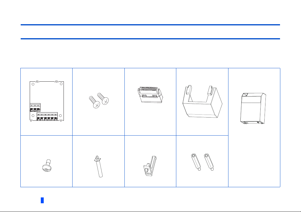
1.1.1 Product confirmation
Check the enclosed items.
Plug-in option: 1
Mounting screw (M3 × 8
mm): 2
(Refer to page 10, page
12.)
Junction connector: 1
(Refer to page 10, page
12.)
Option small cover: 1
(Refer to page 12.)
Front cover for plug-in
option: 1
(Refer to page 10, page
12.)
Recessed neck screw
(M3 × 7): 1
(Refer to page 10, page
12.)
6
PRE-OPERATION INSTRUCTIONS
Straight spacer: 1
(Refer to page 10, page
12.)
L-shaped spacer: 1
(Refer to page 10, page
12.)
Hexagon spacer: 2
(Refer to page 10, page
12.)
Page 7
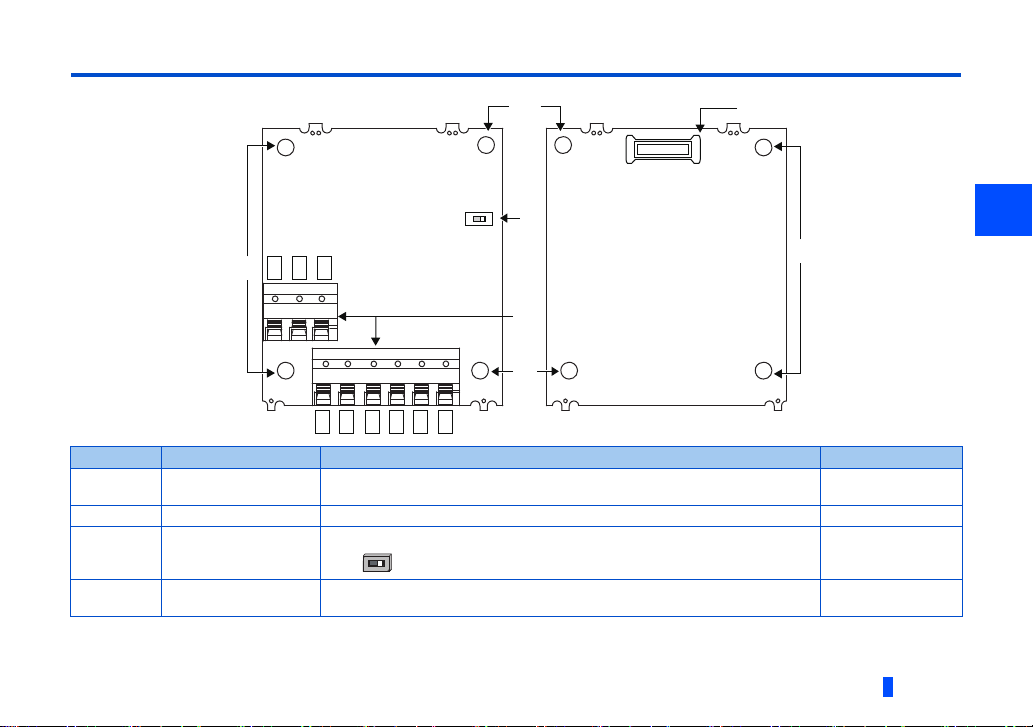
1.2 Component names
Front view Rear view
(a)
(d)
SW1
1A
1B
1C
2A
2B
2C
3A
3B
3C
(a)
O
N
(a)
(a)
(c)
(b)
O
N
1
Symbol Name Description Refer to page
a Mounting hole
b Terminal block Used for connecting devices that receive signals from the inverter. 17
c
Switch for
manufacturer setting
(SW1)
d Connector
Used to fix this product to the inverter by inserting a mounting screw or a
spacer.
Switch for manufacturer setting. Do not change the initial setting.
(OFF )
Connected to the junction connector, which is connected to the option
connector on the inverter.
9
─
9
PRE-OPERATION INSTRUCTIONS
7
Page 8

1.3 Specifications
NOTE
Type of output signal
1 changeover contact output (three relays provided)
Contact capacity
230 VAC...0.3 A
30 VDC...0.3 A
• Use contacts within the rated capacity. Failure to do so may cause contacts to wear out quickly or to be welded.
8
PRE-OPERATION INSTRUCTIONS
Page 9

2 INSTALLATION AND WIRING
NOTE
2.1 Pre-installation instructions
Check that the inverter's input power and the control circuit power are both OFF.
CAUTION
• Do not install or remove this product while the inverter power is ON. Doing so may damage the inverter or this product.
• To avoid damage due to static electricity, static electricity in your body must be discharged before you touch this product.
2.2 Installation procedure
Installing the option
The FR-E800 series inverter has only one plug-in option connector.
• Ensure the control circuit terminals are wired before installing the plug-in option. They cannot be wired after the plug-in
option is installed.
• When installing the plug-in option, prevent cables being caught between parts. Otherwise the inverter and the option may be
damaged.
2
INSTALLATION AND WIRING
9
Page 10
For the FR-E820-0175(3.7K) or lower, FR-E840-0170(7.5K) or lower, and FR-E860-0120(7.5K) or lower
Ensure no burr is left.
2. Front cover for plug-in option
1. Remove the inverter front cover. (Refer to the FR-E800 Instruction Manual (Connection) for instructions to remove the
cover.)
2. Use a nipper or the like to cut off the bottom of the front cover for plug-in option.
3. Fit the L-shaped spacer, straight spacer, and junction connector to the plug-in option as shown in the figure on the page
11. Fit the junction connector to the guide of the connector of the plug-in option, and insert the junction connector as far
as it goes. Fit the L-shaped spacer to the plug-in option so that the lower edge of the option placed on the ridge of the
spacer.
10
INSTALLATION AND WIRING
Page 11

4. Install the hexagon spacers to the inverter.
3. Straight spacer
3. L-shaped spacer
3. Hexagon spacer
4. Hexagon spacer
3. Junction connector
5. Plug-in option
6. Mounting screw
6. Mounting screw
8. Recessed neck screw
8. Front cover for plug-in option
5. Fit the junction connector, which has been connected to the plug-in option, to the guide of the option connector on the
inverter, and insert the junction connector as far as it goes.
6. Fasten this product to the inverter using the two mounting screws through the holes on either side (tightening torque 0.33
to 0.40 N·m). If the connector is not inserted deep enough, the screws cannot be tightened properly. Check the
connector.
7. Connect cables to the terminal block of the plug-in option. (Refer to page 17 for the wiring.)
8. After wiring of the plug-in option has been completed, mount the front cover for the plug-in option to the inverter.
2
INSTALLATION AND WIRING
11
Page 12

For the FR-E820-0240(5.5K) or higher
Ensure no burr is left.
Lower front cover
Upper front
cover
Dummy cover
1. Remove the upper front cover and the lower front cover from the inverter. (Refer to the FR-E800 Instruction Manual
(Connection) for instructions to remove the covers.)
2. Use a nipper or the like to cut off the dummy cover of the lower front cover in order to install the option small cover.
3. Use a nipper or the like to cut off the bottom of the front cover for plug-in option. (For details, refer to page 10.)
4. Fit the L-shaped spacer, straight spacer, and junction connector to the plug-in option as shown in the figure on the page
14. Fit the junction connector to the guide of the connector of the plug-in option, and insert the junction connector as far
as it goes. Fit the L-shaped spacer to the plug-in option so that the lower edge of the option placed on the ridge of the
spacer.
12
INSTALLATION AND WIRING
Page 13

5. Install the hexagon spacers to the inverter.
10. Option small cover
6. Fit the junction connector, which has been connected to the plug-in option, to the guide of the option connector on the
inverter, and insert the junction connector as far as it goes.
7. Fasten this product to the inverter using the two mounting screws through the holes on either side (tightening torque 0.33
to 0.40 N·m). If the connector is not inserted deep enough, the screws cannot be tightened properly. Check the
connector.
8. Connect cables to the terminal block of the plug-in option. (Refer to page 17 for the wiring.)
9. After wiring of the plug-in option has been completed, mount the front cover for the plug-in option to the inverter.
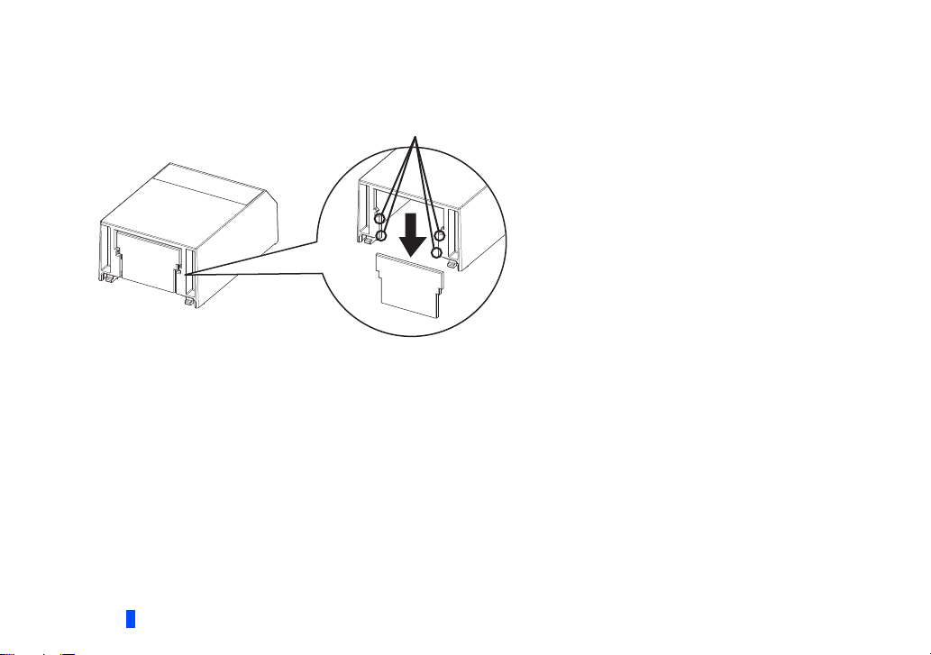
10. Install the option small cover to the front cover for plug-in option by inserting the small cover into the front cover and slide
it toward the rear of the inverter.
2
INSTALLATION AND WIRING
13
Page 14

11. Install the lower front cover to the inverter.
6. Plug-in option
10. Front cover for
plug-in option
9. Recessed
neck screw
7. Mounting screw
10. Option small cover
11. Lower front cover
Drawing at completion of installation
7. Mounting
screw
7. Mounting screw
4. Hexagon spacer
4. Junction connector
4. Straight
spacer
5. Hexagon spacer
4. L-shaped spacer
6. Plug-in option
14
INSTALLATION AND WIRING
Page 15

Insertion positions for screws and spacers
L-shaped spacer
Mounting screw
Mounting screw
Connector
Straight spacer
Insertion positions for screws and spacers
2
INSTALLATION AND WIRING
15
Page 16

NOTE
• When the junction connector is installed to the plug-in option, the option is fixed with the hooks of the connector. The
junction connector cannot be removed from the plug-in option.
• When removing the front cover for plug-in option from the inverter, note that the recessed neck screw cannot be removed
from the front cover for plug-in option.
• When installing/removing the plug-in option, hold the sides of the option. Do not press on the parts on the option circuit
board. Stress applied to the parts by pressing, etc. may cause a failure.
• Be careful not to drop mounting screws during the installation or removal of the plug-in option.
• When the inverter cannot recognize the option due to improper installation or any reason, the protective function (E.1) is
activated and the inverter cannot be operated.
Mounted position Fault indication
Option connector
• When removing the plug-in option, remove the two screws on either side, and then pull it straight out. Pressure applied to
the option connector and to the option board may break the option.
16
INSTALLATION AND WIRING
Page 17

2.3 Wiring
10mm
Crumpled tip
Wires are not inserted
into the sleeve
Unstranded
wires
Damaged
WireWire
SleeveSleeve
0 to 0.5 mm0 to 0.5 mm
1. For the wiring, strip off the sheath of a cable, and use it with a blade terminal. For single wire, the stripped wire can be
used without crimp terminal. Connect the end of wires (crimp terminal or stranded wire) to the terminal block.
Strip the signal wires as shown below. If too much of the wire is stripped, a short circuit may occur with neighboring wires.
If not enough of the wire is stripped, wires may become loose and fall out.
Twist the stripped end of wires to prevent them from fraying. Do not solder it.
Wire strip length
Crimp the terminals on the wire.
Insert wires to the crimp terminal, and check that the wires come out for about 0 to 0.5 mm from a sleeve.
Check the condition of the crimp terminals after crimping. Do not use the crimp terminals of which the crimping is
inappropriate, or the face is damaged.
2
CAUTION
INSTALLATION AND WIRING
• After wiring, wire offcuts must not be left in the inverter. They may cause a fault, failure or malfunction.
17
Page 18

Crimp terminals commercially available (as of December 2019. The product may be changed without notice.)
Wire
gauge
(mm2)
0.3 AI 0,34-10TQ — —
0.5 AI 0,5-10WH — AI 0,5-10WH-GB
0.75 AI 0,75-10GY A 0,75-10 AI 0,75-10GY-GB
1 AI 1-10RD A 1-10 AI 1-10RD/1000GB
1.25, 1.5 AI 1,5-10BK A 1,5-10 —
0.75
(for two
cables)
Wire gauge (mm2)
0.3 to 0.75 BT 0.75-11 VC 0.75 NICHIFU Co., Ltd. NH 69
With insulation
sleeve
AI-TWIN 2 × 0,75-10GY — —
*1 A ferrule terminal with an insulation sleeve compatible with the MTW wire which has a thick wire insulation.
Blade terminal
part No.
Ferrule part No.
Without
insulation sleeve
Insulation cap
part No.
For UL wire
Manufacturer
*1
Manufacturer
Phoenix Contact
Co., Ltd.
Crimping tool
model No.
Crimping tool
model No.
CRIMPFOX 6
18
INSTALLATION AND WIRING
Page 19

2. Insert the wire into the terminal block.
Flathead screwdriver
Open/close button
When using single wire or stranded wires without crimp terminal, push an open/close button all the way down with a
flathead screwdriver, and insert the wire.
Open/close button
Flathead screwdriver
•Wire removal
Pull the wire while pushing the open/close button all the way down firmly with a flathead screwdriver.
2
INSTALLATION AND WIRING
19
Page 20

NOTE
• When using stranded wires without crimp terminal, twist enough to avoid short circuit with a nearby terminals or wires.
• Pulling out the wire forcefully without pushing the open/close button all the way down may damage the terminal block.
• Use a small flathead screwdriver (tip thickness: 0.4 mm/tip width: 2.5 mm). If a flathead screwdriver with a narrow tip is
used, terminal block may be damaged.
Commercially available products (as of December 2019. The product may be changed without notice.)
Product
name
Screwdriver SZF 0- 0,4 × 2,5 Phoenix Contact Co., Ltd.
• Place the flathead screwdriver vertical to the open/close button. In case the blade tip slips, it may cause an inverter damage
or injury.
Model Manufacturer
20
INSTALLATION AND WIRING
Page 21

3 RELAY OUTPUT
3.1 Internal block diagram
Three signals can be selected among inverter's standard signals (RUN, SU, FU, etc.) to be output as relay contact (1C)
signals.
The following figure is the internal block diagram of the FR-A8AR.
1C
RA1
ControllerConnector
RA2
RA3
1B
1A
2C
2B
2A
3C
3B
3A
3
RELAY OUTPUT
21
Page 22

3.2 Terminals
1A
1B
1C
2A
Ter min al
symbol
1A Normally open contact terminal of relay RA1
1B Normally closed contact terminal of relay RA1
1C Common contact terminal for relay RA1
2A Normally open contact terminal of relay RA2
2B Normally closed contact terminal of relay RA2
2C Common contact terminal for relay RA2
3A Normally open contact terminal of relay RA3
3B Normally closed contact terminal of relay RA3
3C Common contact terminal for relay RA3
*1 The operation of each relay depends on the output signal selected.
22
RELAY OUTPUT
2B
2C
3A
3B
Description
3C
Page 23

3.3 List of parameters for relay output
NOTE
When the FR-A8AR is mounted on the inverter, the following parameters are extended.
Perform the settings as required.
Pr. Pr. Group Name Initial value Setting range
320 M420 RA1 output selection 0 The setting range depends on the inverter. For details,
321 M421 RA2 output selection 1
322 M422 RA3 output selection 4
418 M432
Extension output terminal
filter
9999 5 to 50 ms, 9999
refer to the description of Pr.190 to Pr.196 (Output
terminal function selection) in the FR-E800 Instruction
Manual (Function).
3.4 Parameter setting
Setting output signals
Use Pr.320 to Pr.322 to assign signals to the terminals ABC (1 to 3). The settings of Pr.320 to Pr.322 are the same as those of
Pr.190 to Pr.196 (output terminal function selection). For the details of Pr.190 to Pr.196, refer to the FR-E800 Instruction
Manual (Function).
• All the outputs are shut off when the protective functions (E.1) are activated.
• Negative logic cannot be set.
RELAY OUTPUT
3
23
Page 24

Adjusting the output terminal response level (Pr.418)
NOTE
The response level of the output terminals can be delayed in a range of 5 to 50 ms. (Operation example for the RUN signal.)
Output frequency
Time
Pr.418 = 9999
RUN
RUN
Pr.418 ≠ 9999
ON
ON OFF
Pr.418 Pr.418
OFF
• The response level is not adjusted while Pr.418 = "9999".
• When Pr.157 OL signal output timer is set for the Overload warning (OL) signal output, the OL signal is output when the
set time of (Pr.157 + Pr.418) elapses.
24
RELAY OUTPUT
Page 25

APPENDIX
NOTE
Appendix 1 Instructions for compliance with the EU Directives
The EU Directives are issued to standardize different national regulations of the EU Member States and to
facilitate free movement of the equipment, whose safety is ensured, in the EU territory.
Since 1996, compliance with the EMC Directive that is one of the EU Directives has been legally required. Since
1997, compliance with the Low Voltage Directive, another EU Directive, has been also legally required. When a
manufacturer confirms its equipment to be compliant with the EMC Directive and the Low Voltage Directive, the
manufacturer must declare the conformity and affix the CE marking.
• The authorized representative in the EU
The authorized representative in the EU is shown below.
Name: Mitsubishi Electric Europe B.V.
Address: Mitsubishi-Electric-Platz 1, 40882 Ratingen, Germany
•Note
To use this product in the EU, the operating capacity of the relay outputs should be 30 VDC, 0.3 A. (Relay output has basic
isolation from the inverter internal circuit.)
EMC Directive
We declare that this product conforms with the EMC Directive when installed in a compatible inverter, and affix the CE marking
on the packaging plate.
• EMC Directive: 2014/30/EC
• Standard(s): EN 61800-3:2004+A1:2012 (Second environment / PDS Category "C3")
Note
• To install and wire the inverter, refer to the "Instructions for compliance with the EU Directives" in the Instruction Manual
enclosed with the inverter.
• Confirm that the final integrated system with the inverter conforms with the EMC Directive.
APPENDIX
25
Page 26

Appendix 2 Instructions for EAC
□ ○ ○ ○○○
Symbol Year Month Control number
SERIAL
SERIAL
The product certified in compliance with the Eurasian Conformity has the EAC marking on the packaging plate.
Note: EAC marking
In 2010, three countries (Russia, Belarus, and Kazakhstan) established a Customs Union for the purposes of
revitalizing the economy by forming a large economic bloc by abolishing or reducing tariffs and unifying regulatory
procedures for the handling of articles.
Products to be distributed over these three countries of the Customs Union must comply with the Customs Union
Technical Regulations (CU-TR), and the EAC marking must be affixed to the products.
For information on the country of origin, manufacture year and month, and authorized sales representative
(importer) in the CU area of this product, refer to the following:
• Country of origin indication
Check the package of this product.
Example: MADE IN JAPAN
• Manufactured year and month
Check the SERIAL number indicated on this product.
The SERIAL consists of one symbol, two characters indicating the production year and month, and
three characters indicating the control number. The last digit of the production year is indicated as the
Year, and the Month is indicated by 1 to 9, X (October), Y (November), or Z (December).
• Authorized sales representative (importer) in the CU area
The authorized sales representative (importer) in the CU area is shown below.
Name: Mitsubishi Electric (Russia) LLC
Address: 52, bld 1 Kosmodamianskaya Nab 115054, Moscow, Russia
Phone: +7 (495) 721-2070
Fax: +7 (495) 721-2071
26
APPENDIX
Page 27

Appendix 3 Restricted Use of Hazardous Substances in Electronic and
⭥ಘ⭥ᆀӗ૱ᴹᇣ⢙䍘䲀ࡦ֯⭘ḷ䇶㾱≲
ᵜӗ૱ѝᡰᴹⲴᴹᇣ⢙䍘Ⲵ〠ǃ䟿ǃᴹ䜘Ԧྲл㺘ᡰ⽪DŽ
Ьӗ૱ѝᡰᴹᇣ⢙䍘Ⲵ〠৺䟿
к㺘ᦞ 6-7Ⲵ㿴ᇊ㕆ࡦDŽ
ƻ˖㺘⽪䈕ᴹᇣ⢙䍘൘䈕䜘Ԧᡰᴹ൷䍘ᶀᯉѝⲴ䟿൷൘ *%7㿴ᇊⲴ䲀䟿㾱≲ԕлDŽ
h˖㺘⽪䈕ᴹᇣ⢙䍘൘䈕䜘ԦⲴ㠣ቁа⿽൷䍘ᶀᯉѝⲴ䟿䎵ࠪ *%7㿴ᇊⲴ䲀䟿㾱≲DŽ
ণ֯㺘ѝ䇠䖭Ѫ hˈṩᦞӗ૱රˈҏ㜭Պᴹᴹᇣ⢙䍘Ⲵ䟿Ѫ䲀ࡦ٬ԕлⲴᛵߥDŽ
ṩᦞӗ૱රˈа䜘࠶䜘Ԧ㜭н൘ӗ૱ѝDŽ
⧥ູؓᣚֵ⭞ᵕ䲆ḽ䇼
䜞Ԭ〦
䫻
3E
ཐ⓪ӂ㤥䟐
3%'(
⊔
+J
䭿
&G
ޣԭ䬢
&U9,
ཐ⓪㚊㤥
3%%
ᴿᇩ⢟䍞
⭥䐟ᶯ㓴Ԧ˄ᤜঠࡧ⭥䐟ᶯ৺ަᶴᡀⲴ䴦䜘Ԧˈ
ྲ⭥䱫ǃ⭥ᇩǃ䳶ᡀ⭥䐟ǃ䘎᧕ಘㅹ˅ǃ⭥ᆀ䜘Ԧ
h
h
ƻ
ƻ
ƻ
ƻ
ƻ
ƻ
h
ƻ
ƻ
ƻ
ƻ
ƻ
ƻ
ƻ
ƻ
ƻ
ƻ
ƻ
ƻ
ƻ
ƻ
ƻ
䠁༣փǃ䠁䜘Ԧ
ṁ㜲༣փǃṁ㜲䜘Ԧ
㷪эǃ⭥㓯
Electrical Products
The mark of restricted use of hazardous substances in electronic and electrical products is applied to the product as follows
based on the “Management Methods for the Restriction of the Use of Hazardous Substances in Electrical and Electronic
Products” of the People's Republic of China.
APPENDIX
27
Page 28

Appendix 4 Referenced Standard (Requirement of Chinese
standardized law)
This Product is designed and manufactured accordance with following Chinese standards.
EMC: GB/T 12668.3
28
APPENDIX
Page 29

MEMO
APPENDIX
29
Page 30

MEMO
30
IB(NA)-0600883ENG-A
APPENDIX
Page 31

REVISIONS
*The manual number is given on the bottom left of the back cover.
Revision date *Manual number Revision
Dec. 2019 IB(NA)-0600883ENG-A First edition
31
Page 32

INVERTER
HEAD OFFICE: TOKYO BUILDING 2-7-3, MARUNOUCHI, CHIYODA-KU, TOKYO 100-8310, JAPAN
IB(NA)-0600883ENG-A(1912) MEE Printed in Japan Specifications subject to change without notice.
 Loading...