

Mitsubishi Electric FR-A8APR Instruction Manual

INVERTER
Plug-in option
FR-A8APR
INSTRUCTION MANUAL
Resolver interface
Orientation control
Resolver (encoder) feedback control
Vector control
PRE-OPERATION INSTRUCTIONS
INSTALLATION AND WIRING
PARAME TER
ORIENTATION CONTROL
RESOLVER (ENCODER) FEEDBACK
CONTROL
VECTOR CONTROL
1
2
3
4
5
6
Thank you for choosing this Mitsubishi inverter plug-in option.
Warning
Caution
Caution
This Instruction Manual provides handling information and precautions for use of this product. Incorrect handling might cause an unexpected
fault. Before using this product, always read this Instruction Manual carefully to use this product correctly.
Please forward this Instruction Manual to the end user.
Safety instructions
Do not attempt to install, operate, maintain or inspect the product until you have read through this Instruction Manual and appended
documents carefully and can use the equipment correctly. Do not use this product until you have a full knowledge of the equipment, safety
information and instructions. In this Instruction Manual, the safety instruction levels are classified into "Warning" and "Caution".
The level may even lead to a serious consequence according to conditions. Both instruction levels must be followed
because these are important to personal safety.
Electric Shock Prevention
Incorrect handling may cause hazardous conditions, resulting in death or severe injury.
Incorrect handling may cause hazardous conditions, resulting in medium or slight injury, or may cause only material
damage.
Warning
While the inverter power is ON, do not open the front cover or the wiring cover. Do not run the inverter with the front cover or the wiring cover removed. Otherwise
you may access the exposed high voltage terminals or the charging part of the circuitry and get an electric shock.
Do not remove the inverter front cover even if the power supply is disconnected. The only exception for this would be when performing wiring and periodic
inspection. You may accidentally touch the charged inverter circuits and get an electric shock.
Before wiring or inspection, LED indication of the inverter unit operation panel must be switched OFF. Any person who is involved in wiring or inspection shall wait
for at least 10 minutes after the power supply has been switched OFF and check that there is no residual voltage using a tester or the like. For some time after the
power-OFF, a high voltage remains in the smoothing capacitor, and it is dangerous.
Any person who is involved in wiring or inspection of this equipment shall be fully competent to do the work.
The plug-in option must be installed before wiring. Otherwise you may get an electric shock or be injured.
Do not touch the plug-in option or handle the cables with wet hands. Otherwise you may get an electric shock.
Do not subject the cables to scratches, excessive stress, heavy loads or pinching. Otherwise you may get an electric shock.
Injury Prevention
Caution
The voltage applied to each terminal must be the ones specified in the Instruction Manual. Otherwise a burst, damage, etc. may occur.
The cables must be connected to the correct terminals. Otherwise a burst, damage, etc. may occur.
The polarity (+ and -) must be correct. Otherwise a burst or damage may occur.
While power is ON or for some time after power OFF, do not touch the inverter as it will be extremely hot. Touching these devices may cause a burn.
2
Additional Instructions
The following instructions must be also followed. If the product is handled incorrectly, it may cause unexpected fault, an injury, or an electric
shock.
Caution
Transportation and mounting
Do not install or operate the plug-in option if it is damaged or has parts missing.
Do not stand or rest heavy objects on the product.
The mounting orientation must be correct.
Foreign conductive objects must be prevented from entering the inverter. That includes screws and metal fragments or other flammable substance such as oil.
If halogen-based materials (fluorine, chlorine, bromine, iodine, etc.) infiltrate into a Mitsubishi product, the product will be damaged. Halogen-based materials are
often included in fumigant, which is used to sterilize or disinfest wooden packages. When packaging, prevent residual fumigant components from being infiltrated
into Mitsubishi products, or use an alternative sterilization or disinfection method (heat disinfection, etc.) for packaging. Sterilization of disinfection of wooden
package should also be performed before packaging the product.
Trial run
Before starting operation, each parameter must be confirmed and adjusted. A failure to do so may cause some ma chines to make unexpected motions.
Warning
Usage
Do not modify the equipment.
Do not perform parts removal which is not instructed in this manual. Doing so may lead to fault or damage of the product.
Caution
Usage
When parameter clear or all parameter clear is performed, the required parameters must be set again before starting operations. Because all parameters return to
their initial values.
Static electricity in your body must be discharged before you touch the product.
Maintenance, inspection and parts replacement
Do not carry out a megger (insulation resistance) test.
Disposal
The product must be treated as industrial waste.
Many of the diagrams and drawings in this Instruction Manual show the inverter without a cover or partially open for explanation. Never operate the inverter in this
General instruction
manner. The cover must be reinstalled and the instructions in the Instruction Manual must be followed when operating the inverter.
3

─ CONTENTS ─
1 PRE-OPERATION INSTRUCTIONS 6
1.1 Unpacking and product confirmation.......................................................................................................6
1.1.1 Product confirmation....................................................................................................................................... 6
1.1.2 SERIAL number check ...................................................................................................................................7
1.2 Component names .....................................................................................................................................8
2 INSTALLATION AND WIRING 9
2.1 Pre-installation instructions ......................................................................................................................9
2.2 Installation procedure ................................................................................................................................9
2.3 Wiring ........................................................................................................................................................12
2.4 Terminals...................................................................................................................................................15
3 PARAMETER 16
3.1 Extended parameter list...........................................................................................................................16
3.2 Function differences from the FR-A8AP ................................................................................................18
3.3 Protective function ...................................................................................................................................20
4 ORIENTATION CONTROL 21
4.1 Wiring example .........................................................................................................................................21
4.2 Terminals...................................................................................................................................................22
4.3 Specifications ...........................................................................................................................................23
5 RESOLVER (ENCODER) FEEDBACK CONTROL 24
5.1 Wiring examples .......................................................................................................................................24
5.2 Specifications ...........................................................................................................................................25
4

6 VECTOR CONTROL 26
6.1 Wiring examples .......................................................................................................................................26
6.2 Setting procedure of vector control for motor with resolver ...............................................................29
6.3 Vector control for PM motor with resolver.............................................................................................30
6.4 Offline auto tuning....................................................................................................................................31
6.5 Resolver position tuning..........................................................................................................................33
6.6 Specifications ...........................................................................................................................................36
<Notes on descriptions in this Instruction Manual>
Connection diagrams in this Instruction Manual appear with the control logic of the input terminals as sink logic, unless
otherwise specified.
5
1 PRE-OPERATION INSTRUCTIONS
1.1 Unpacking and product confirmation
Take the plug-in option out of the package, check the product name, and confirm that the product is as you ordered and intact.
This product is a plug-in option dedicated for the FR-A800 series.
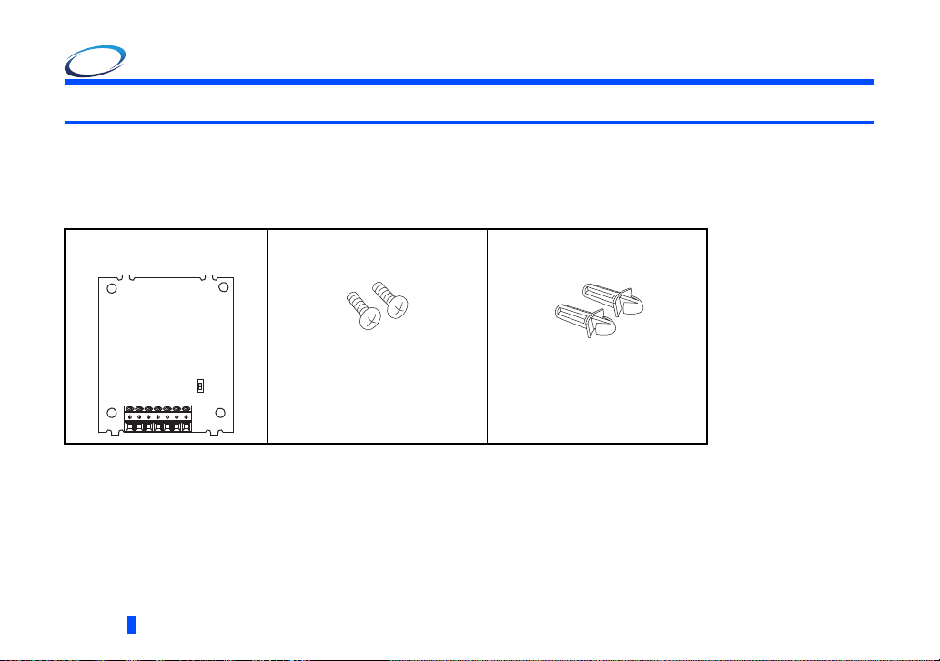
1.1.1 Product confirmation
Check the enclosed items.
Plug-in option
.................................................. 1
SW1
6
PRE-OPERATION INSTRUCTIONS
Mounting screw (M3
...................... 2 (Refer to
8 mm)
page 9
Spacer
)
......................2 (Refer to
page 9
)
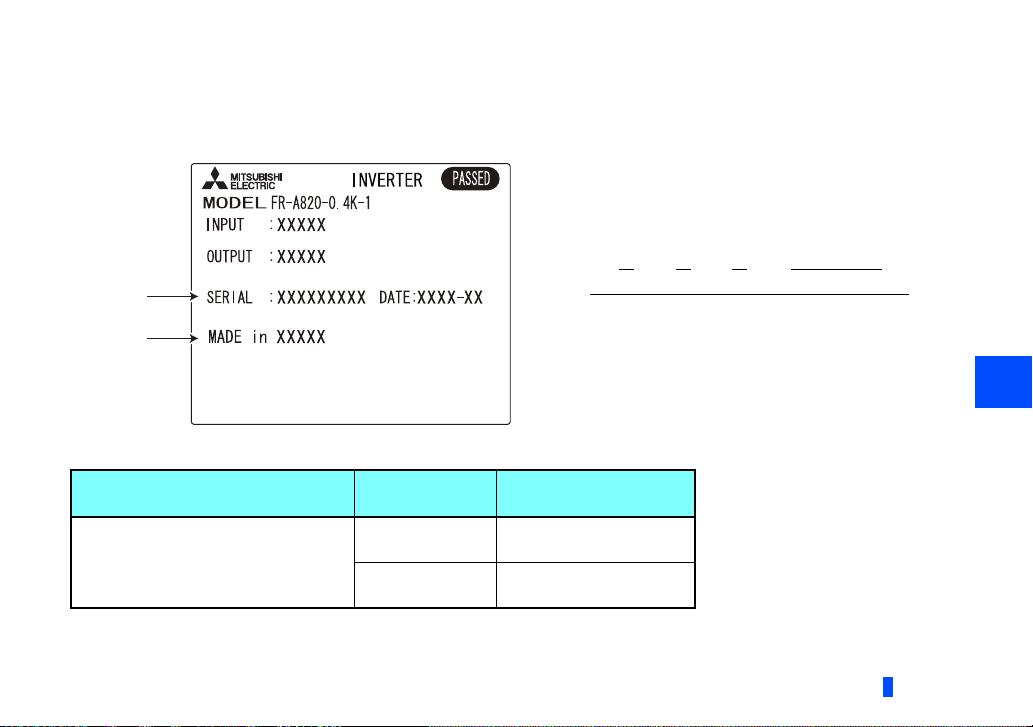
1.1.2 SERIAL number check
SERIAL
number
Country
of origin
The FR-A8APR can be used for the inverter models listed below with the following SERIAL number or later. Check the SERIAL
number indicated on the inverter rating plate or package.
Rating plate example
Symbol Year Month Control number
SERIAL
The SERIAL consists of one symbol, two characters indicating the
production year and month, and six characters indicating the
control number.
The last digit of the production year is indicated as the Year, and
the Month is indicated by 1 to 9, X (October), Y (November), or Z
(December).
FR-A800 series
Model
Country of
origin indication
SERIAL number
1
FR-A820-00046(0.4K) to 04750(90K)
FR-A840-00023(0.4K) to 06830(280K)
FR-A842-07700(315K) to 12120(500K)
FR-A846-00023(0.4K) to 03610(132K)
MADE in Japan 52 or later
MADE in China 53 or later
PRE-OPERATION INSTRUCTIONS
7
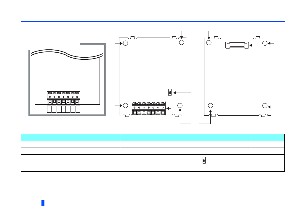
1.2 Component names
Front view Rear view
Terminal layout
(a) (d)
(a)
(b)
(a)
(a)
(a)
(a)
(c)
SW1
R1
R2
S2S4S1
S3
CM
Symbol Name Description Refer to page
a Mounting hole Fixes the option to the inverter with screws, or installs spacers. 9
b Terminal block Connected with a resolver. 15
c Switch for manufacturer setting (SW1)
d Connector Connects to the option connector of the inverter. 9
8
PRE-OPERATION INSTRUCTIONS
Do not change the initially-set status. (OFF )
―
2 INSTALLATION AND WIRING
2.1 Pre-installation instructions
Check that the inverter's input power and the control circuit power are both OFF.
Caution
With input power ON, do not install or remove the plug-in option. Otherwise, the inverter and plug-in option may be damaged.
To avoid damage due to static electricity, static electricity in your body must be discharged before you touch the product.
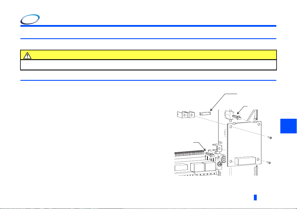
2.2 Installation procedure
(1) Remove the inverter front cover. (Refer to Chapter 2 of
the Instruction Manual (Detailed) of the inverter for details
on how to remove the front cover.)
(2) For the two mounting holes (as shown in the next page)
that will not be tightened with mounting screws, insert
spacers.
(3) Fit the connector of the plug-in option to the guide of the
connector on the inverter unit side, and insert the plug-in
option as far as it goes.
(4) Fit the two locations, the left and right, of the plug-in
option securely to the inverter unit by screwing in the
supplied mounting screws. (tightening torque 0.33 N·m to
0.40 N·m) If the screw holes do not line up, the connector
may not be inserted deep enough. Check the connector.
Inverter side
option connector
Spacer
Spacer
Example of installation to connector 1
INSTALLATION AND WIRING
2
9
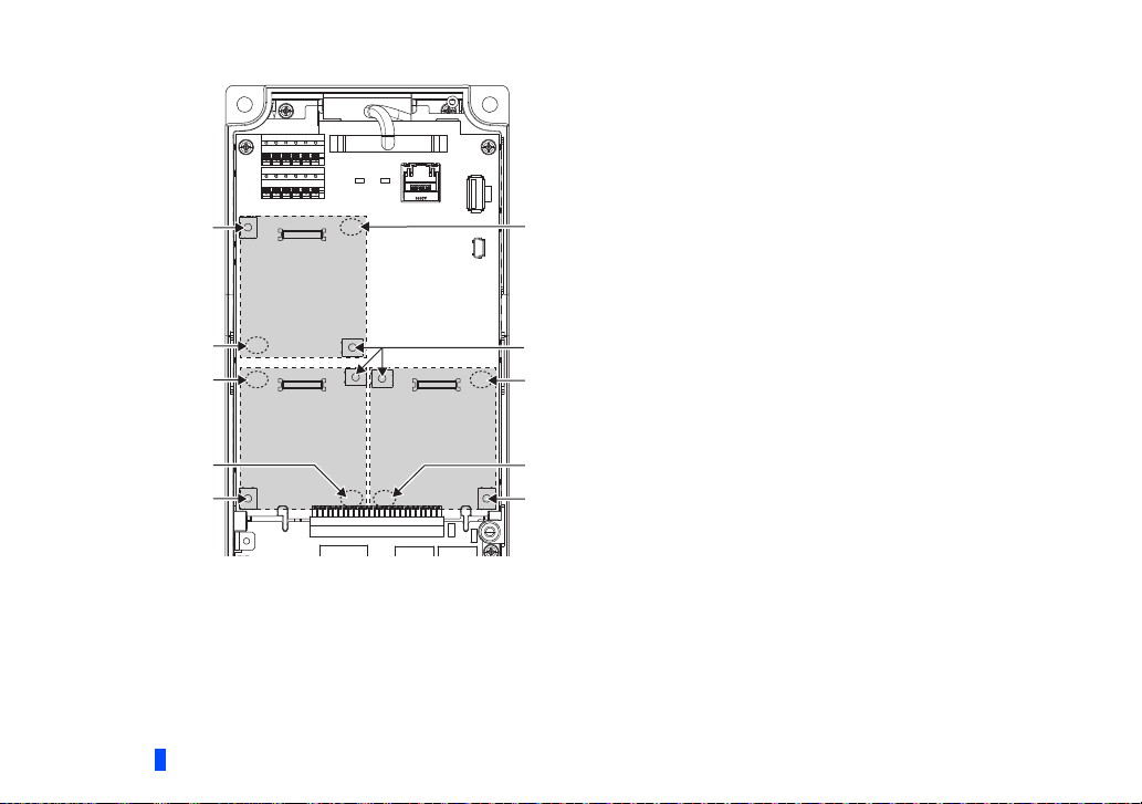
Spacer
Spacer
Spacer
Mounting screw
Mounting screw
Mounting screw
Spacer
Spacer
Spacer
Mounting screw
Connector 1Connector 2
Connector 3
Insertion positions for screws and spacers
10
INSTALLATION AND WIRING
NOTE
• When mounting/removing the plug-in option, hold the sides of the option. Do not press on the parts on the option
circuit board. Stress applied to the parts by pressing, etc. may cause a failure.
• Caution must be applied to mounting screws falling off when removing and mounting the plug-in option.
• If the FR-A8APR and the FR-A8AP are installed together, the FR-A8AP is disabled.
• Only one option can be used. When multiple options are mounted, priority is given to option connectors 1, 2 and 3 on
the inverter in this order, and options having a lower priority do not function.
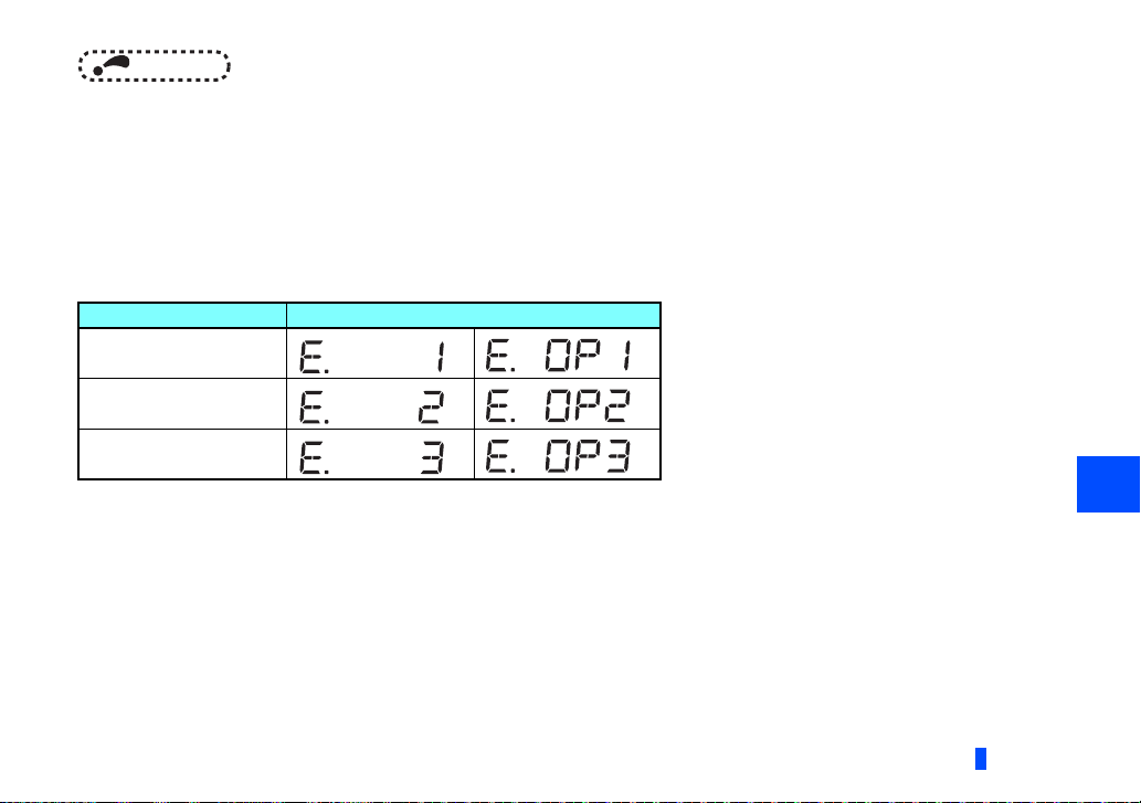
• When the inverter cannot recognize that the option unit is mounted due to improper installation, etc., or when an
option unit fault occurs, the protective function (E.1 to E.3 or E.OP1 to E.OP3) is activated and the inverter cannot be
operated. A different indication will appear according to the mounted position (option connector 1 to 3).
Mounted position Fault indication
Option connector 1
Option connector 2
Option connector 3
• When removing the plug-in option, remove the two screws on the left and right, then pull it straight out. Pressure
applied to the connector and to the option board may break the option.
2
INSTALLATION AND WIRING
11
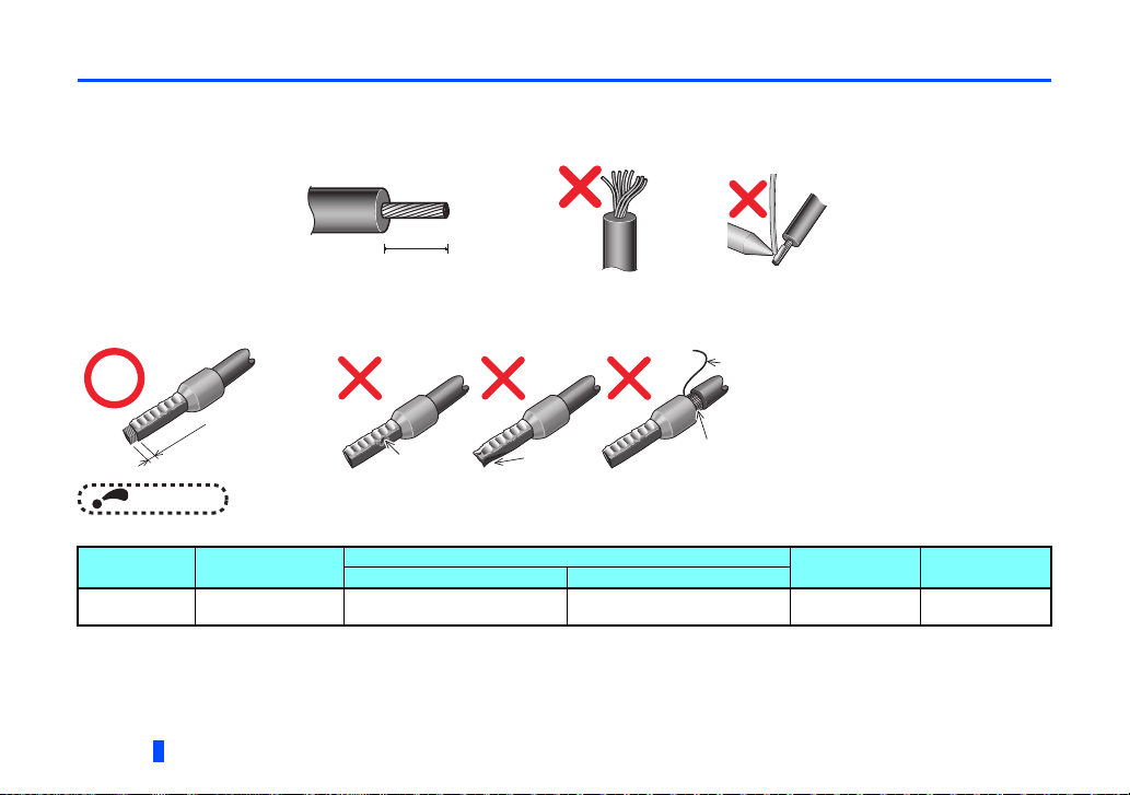
2.3 Wiring
NOTE
5 mm
Wire
Sleeve
0 to 0.5 mm
(1) Strip off the sheath of the signal cable from the resolver for the below length. If the length of the sheath peeled is too long,
a short circuit may occur with neighboring wires. If the length is too short, wires might come off.
Wire the stripped signal cable after twisting it to prevent it from becoming loose. In addition, do not solder it.
Cable stripping length
For connecting the FR-A8APR, use a blade terminal as necessary.
When using the blade terminal, use care so that the twisted wires do not come out.
Unstranded
Wire
Sleeve
wires
0 to 0.5 mm
Damaged
Crumpled tip
• Blade terminals commercially available (as of January 2015. The product may be changed without notice.)
Ter min al
screw size
Wire size (mm2)
Ferrule terminal model
M2 0.3 to 0.5 Al 0,5-6WH A 0,5-6
12
INSTALLATION AND WIRING
Wires are not inserted
into the sleeve
Manufacturer
Phoenix Contact
Co.,Ltd.
Crimping tool
nameWith insulation sleeve Without insulation sleeve
CRIMPFOX 6
 Loading...