

Page 1

INVERTER
Plug-in option
FR-A8APD
INSTRUCTION MANUAL
Encoder pulse divider
PRE-OPERATION INSTRUCTIONS
INSTALLATION AND WIRING
ENCODER PULSE DIVIDER
PROTECTIVE FUNCTIONS
1
2
3
4
Page 2

Thank you for choosing this Mitsubishi Electric inverter plug-in option.
WARNING
CAUTION
CAUTION
This Instruction Manual provides handling information and precautions for use of this product. Incorrect handling might cause an unexpected
fault. Before using this product, read all relevant instruction manuals carefully to ensure proper use.
Please forward this Instruction Manual to the end user.
Safety instructions
Do not attempt to install, operate, maintain or inspect this product until you have read this Instruction Manual and appended documents
carefully. Do not use this product until you have a full knowledge of this product mechanism, safety information and instructions. In this
Instruction Manual, the safety instruction levels are classified into "WARNING" and "CAUTION".
Incorrect handling may cause hazardous conditions, resulting in death or severe injury.
Incorrect handling may cause hazardous conditions, resulting in medium or slight injury, or may cause only
material damage.
Note that even the level may lead to a serious consequence depending on conditions. Be sure to follow the
instructions of both levels as they are critical to personnel safety.
Electric shock prevention
WARNING
Do not remove the front cover or the wiring cover of the inverter while the inverter power is ON. Do not operate the inverter with any cover or wiring cover removed,
as accidental contact with exposed high-voltage terminals and internal components may occur, resulting in an electrical shock.
Even if power is OFF, do not remove the front cover of the inverter except for wiring or periodic inspection as you may accidentally touch the charged circuits and
get an electric shock.
Before wiring or inspection, check that the display of the inverter operation panel is OFF. Any person who is involved in wiring or inspection shall wait for 10 minutes
or longer after power OFF and check that there are no residual voltage using a tester or the like. The capacitor is charged with high voltage for some time after
power OFF, and it is dangerous.
Any person who is involved in wiring or inspection of this product shall be fully competent to do the work.
This product must be installed before wiring. Otherwise you may get an electric shock or be injured.
Do not subject the cables to scratches, excessive stress, heavy loads or pinching. Doing so may cause an electric shock.
Do not touch this product or ha ndle the cables with wet hands. Doing so may cause an electric sh ock.
Injury prevention
CAUTION
The voltage applied to each terminal must be as specified in the Instruction Manual. Otherwise a burst, damage, etc. may occur.
The cables must be connected to the correct terminals. Otherwise a burst, damage, etc. may occur.
The polarity (+ and -) must be correct. Otherwise a burst, damage, etc. may occur.
While power is ON or for some time after power OFF, do not touch the inverter as it will be extremely hot. Doing so may cause a burn.
2
Page 3
Additional instructions
The following instructions must be also followed. If this product is handled incorrectly, it may cause unexpected fault, an injury, or an electric
shock.
CAUTION
Transportation and installation
Do not stand or place heavy objects on this product.
The installing orientation of this product must be correct.
Do not install or operate this product if it is damaged or has parts missing.
Foreign conductive objects must be prevented from entering the inverter. That includes screws and metal fragments or other flammable substance such as oil.
If halogen-based materials (fluorine, chlorine, bromine, iodine, etc.), included in fumigants to sterilize or disinfect wooden packages, infiltrate into this product, the
product may be damaged. Prevent residual fumigant components from being infiltrated into the product when packaging, or use an alternative sterilization or
disinfection method (heat disinfection, etc.). Note that sterilization or disinfection of wooden package should also be performed before packing the product.
Test operation
Before starting operation, confirm or adjust the parameter settings. Failure to do so may cause some machines to make unexpected motions.
WARNING
Usage
Do not modify this product.
Do not remove any part which is not instructed to be removed in the Instruction Manuals. Doing so may lead to a failure or damage of this product.
CAUTION
Usage
As all parameters return to their initial values after Parameter clear or All parameter clear is performed, the needed parameters for operation of the inverter and this
product must be set again bef ore the operation is started.
To avoid damage to this product due to static electricity, static electricity in your body must be discharged before you touch this product.
Maintenance, inspection and parts replacement
Do not carry out a megger (insulation resistance) test.
Disposal
This product must be treated as industrial waste.
For clarity purpose, illustrations in this Instruction Manual may be drawn with covers or safety guards removed. Ensure all covers and safety guards are properly
General instruction
installed prior to starting operation.
3
Page 4

— CONTENTS —
1 PRE-OPERATION INSTRUCTIONS 5
1.1 Unpacking and product confirmation.......................................................................................................5
1.1.1 Product confirmation.......................................................................................................................................5
1.1.2 SERIAL number check ................................................................................................................................... 6
1.2 Component names .....................................................................................................................................7
2 INSTALLATION AND WIRING 8
2.1 Pre-installation instructions ......................................................................................................................8
2.2 Installation procedure ................................................................................................................................8
2.3 Wiring ........................................................................................................................................................12
2.4 Terminals...................................................................................................................................................14
3 ENCODER PULSE DIVIDER 16
3.1 Connection diagram.................................................................................................................................16
3.2 Parameter related to encoder pulse divider...........................................................................................18
4 PROTECTIVE FUNCTIONS 19
APPENDIX 20
4
Page 5
1 PRE-OPERATION INSTRUCTIONS
NOTE
1.1 Unpacking and product confirmation
Take the product out of the package, check the product name, and confirm that the product is as you ordered and intact.
This product is a plug-in option made for the FR-A800 series inverters.
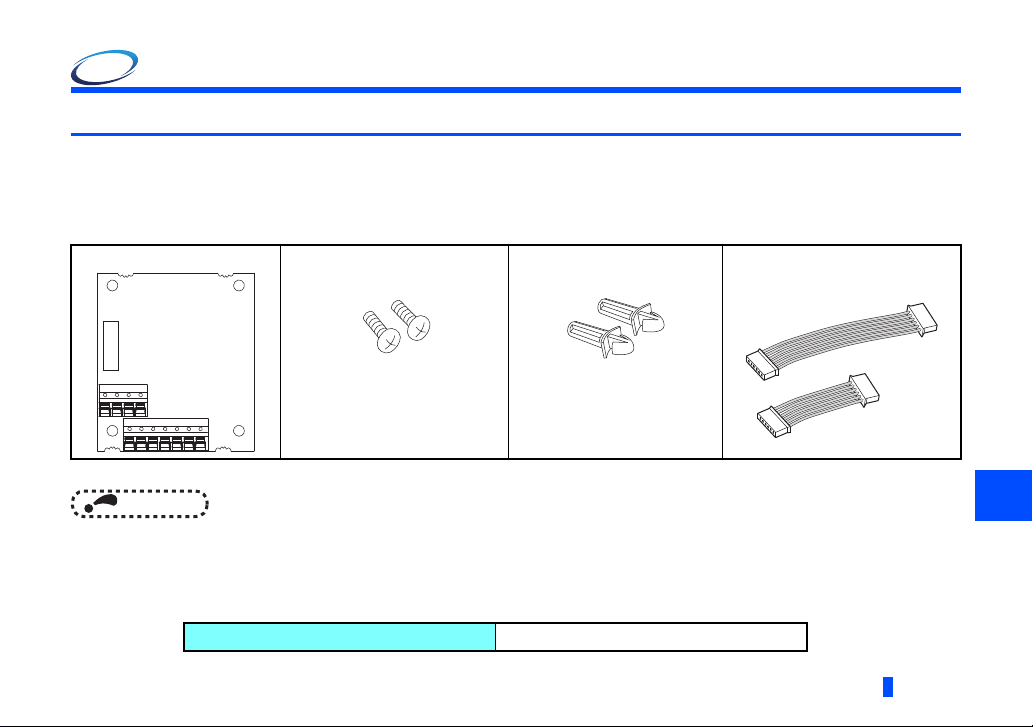
1.1.1 Product confirmation
Check the enclosed items.
Plug-in option: 1
Mounting screw (M3 × 8 mm): 2
page 8
(Refer to
Use either one.
• Connection diagrams in this Instruction Manual appear with the control logic of the input terminals as sink logic, unless
otherwise specified. (For the control logic, refer to the Instruction Manual of the inverter.)
• This product does not function on a standalone basis. Always use this product in combination with either of the
following encoder interface options. Use the enclosed connection cable to connect this product and the encoder
interface option.
Compatible encoder interface options
.)
Spacer: 2
(Refer to
page 8
.)
FR-A8AP and FR-A8APA
PRE-OPERATION INSTRUCTIONS
Encoder interface option connection
cable: 2
(Refer to
page 10
.)
(Long)
(Short)
1
5
Page 6
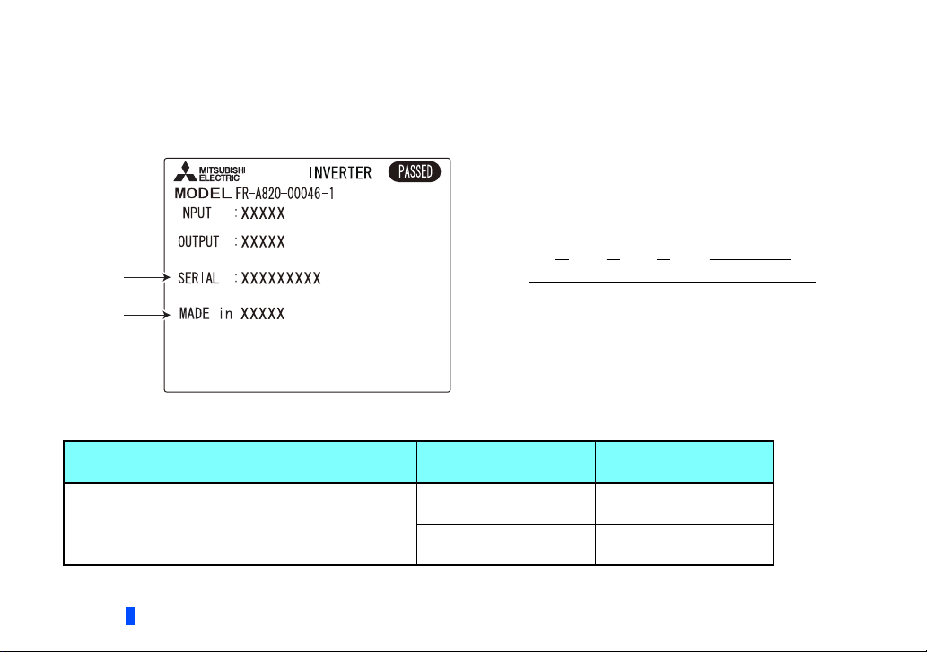
1.1.2 SERIAL number check
SERIAL
number
Country
of origin
The FR-A8APD can be used with the models of inverters listed below which have the following SERIAL number. Check the
SERIAL number indicated on the inverter rating plate or package. For the location of the rating plate, refer to the Instruction
Manual (Detailed) of the inverter.
Rating plate example
Symbol Year Month Control number
SERIAL
The SERIAL consists of one symbol, two characters indicating the
production year and month, and six characters indicating the
control number.
The last digit of the production year is indicated as the Year, and
the Month is indicated by 1 to 9, X (October), Y (November), or Z
(December).
FR-A800 series
Model
Country of origin
indication
SERIAL number
FR-A820-00046(0.4K) to 04750(90K)
FR-A840-00023(0.4K) to 06830(280K)
FR-A842-07700(315K) to 12120(500K)
FR-A846-00023(0.4K) to 03610(132K)
6
PRE-OPERATION INSTRUCTIONS
MADE in Japan 83 or later
MADE in China 84 or later
Page 7
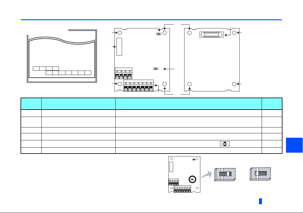
1.2 Component names
Terminal layout
FPB
FPBR
SD
FPA
FPAR
PC2
FPA2 FPB2 FPZ2
FPZ
FPZR
Front view Rear view
SW2
SI SO
(a) (d)
(a)
(a)
(a)
(a)
(c)
(a)
(b)
(e)
(f)
SI (sink) position
(initial status)
SO (source) position
Symbol Name Description
a Mounting hole
b Terminal block
c CON2 connector Used to connect two options. —
d Board mounted option connector Used to connect this product to the option connector on the inverter.
e Switch for manufacturer setting (SW1)
f Sink/source switch (SW2)
Used to fix this product to the inverter by inserting a mounting screw or a spacer.
Used to connect the terminals of this product and a device which receives the
signals from the inverter.
Used to choose the control logic between sink and source. —
This switch allows selection of the control logic between sink and
source.
The switch is initially set to the "SI" position.
SI: Sink (initial position)
SO: Source
Do not change the switch setting from the initial setting ( ).
PRE-OPERATION INSTRUCTIONS
Refer
to page
8
12
8
—
1
7
Page 8
Spacer
Spacer
Option connector
on the inverter
2 INSTALLATION AND WIRING
2.1 Pre-installation instructions
Check that the inverter's input power and the control circuit power are both OFF.
CAUTION
Do not install or remove this product while the inverter power is ON. Doing so may damage the inverter or this product.
To avoid damage due to static electricity, static electricity in your body must be discharged before you touch this product.
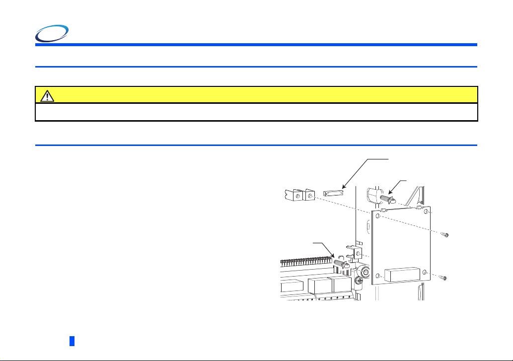
2.2 Installation procedure
(1) Remove the inverter front cover. (Refer to Chapter 2 of the
Instruction Manual (Detailed) of the inverter for instructions
for removing the front cover.)
(2) Insert two spacers into the mounting holes that will not be
filled with mounting screws (see the diagrams on the next
page to identify the holes ).
(3) Fit the board mounted option connector on this product to
the guide of the option connector on the inverter, and insert
the option as far as it goes.
(4) Fasten this product to the inverter using the two mounting
screws through the holes on either side (tightening torque:
0.33 to 0.40 N·m). If the screw holes do not line up, the
connector may not be inserted deep enough. Check the
connector.
Example: Attachment of this product
to connector 1 on the FR-A800
8
INSTALLATION AND WIRING
Page 9

• Insertion positions for screws and spacers
Ethernet connector
Connector 1
Spacer
Mounting screw
Mounting screw
Spacer
Connector 3
FR-A800 FR-A800-E
Mounting screw
Mounting screw
Spacer
Spacer
Spacer
Connector 3
Connector 1Connector 2
Spacer
Mounting screw
Spacer
Spacer
Mounting screw
Attach this product to connector 3.
(Do not attach it to connector 1.)
INSTALLATION AND WIRING
2
9
Page 10

Installation of an encoder interface option
FR-A800-E
FR-A8APA
FR-A8APD
CON2
connector
Option connection
cable (Short)
Option connection
cable (Long)
FR-A800
FR-A8APAFR-A8APD
CON2
connector
Available combinations of the installation location of two options vary by inverter model. Refer to the following to install two
options on the inverter.
Installation example of the FR-A8APD with the FR-A8APA
(1) Attach the FR-A8APA to connector 1 on the inverter (connector 2 can also be used for the FR-A800).
(2) Attach the FR-A8APD to connector 2 on the FR-A800 (another empty connector can also be used for the FR-A800), or
connector 3 on the FR-A800-E.
(3) Connect one of the enclosed option connection cables (refer to page 5) to the CON2 connectors on the FR-A8APD and on
the FR-A8APA.
10
INSTALLATION AND WIRING
Page 11

NOTE
• When installing/removing the plug-in option, hold the sides of the option. Do not press on the parts on the option circuit
board. Stress applied to the parts by pressing, etc. may cause a failure.
• Be careful not to drop mounting screws during the installation or removal of the plug-in option.
• Only one option attached to the option connector with high priority can function at once if more than one option of the
same name are installed together on an inverter. Priority is given to option connectors in descending order (1 to 3),
and options having a lower priority do not function.
• When the inverter cannot recognize the option due to improper installation or any other reason, the protective function
(E.1 to E.3) is activated and the inverter cannot be operated. The indication shown (when a fault occurs) depends on
the connector used (option connector 1 to 3).
Mounted position Fault indication
Option connector 1
Option connector 2
Option connector 3
• When removing the plug-in option, remove the two screws on either side, and then pull it straight out. Pressure applied
to the option connectors and to the option board may break the option.
2
INSTALLATION AND WIRING
11
Page 12

2.3 Wiring
NOTE
5 mm
Crumpled tip
Wires are not inserted
into the sleeve
Unstranded
wires
Damaged
WireWire
SleeveSleeve
0 to 0.5 mm0 to 0.5 mm
(1) Strip the signal wires as shown below. If too much of the wire is stripped, a short circuit may occur with neighboring wires.
If not enough of the wire is stripped, wires may become loose and fall out.
Twist the stripped end of wires to prevent them from fraying. Do not solder it.
Wire strip length
Use appropriate crimp terminals (ferrules, blade terminals, etc.) for these terminal blocks as necessary.
When using the crimp terminal, make sure that the stranded wire do not come out of the terminal.
• Crimp terminals commercially available (as of January 2017. The product may be changed without notice.)
Phoenix Contact Co., Ltd.
Terminal screw size
M2
12
INSTALLATION AND WIRING
Wire gauge (mm2)
0.3 AI 0,34-6TQ A 0,34-7
0.5 Al 0,5-6WH A 0,5-6
With insulation sleeve Without insulation sleeve
Ferrule part No.
Crimping tool model No.
CRIMPFOX 6
Page 13

NICHIFU Co., Ltd.
NOTE
Terminal screw size
M2 0.3 to 0.5 BT 0.75-7 VC 0.75 NH 69
(2) Loosen the terminal screws, and insert each wire into the terminal.
Screw size Tightening torque (N·m)
M2 0.22 to 0.25 0.3 to 0.75
• Under-tightening may cause cable disconnection or malfunction. Over-tightening may cause a short circuit or
• When wiring the RS-485 terminals on the inverter with the plug-in options installed, be careful not to let RS-485 cables
Wire gauge (mm2)
When crimping the blade terminal shown above (noninsulated one), make sure that the twisted stripped
end do not come out of the terminal.
malfunction due to damage to the screw or option unit.
touch the option circuit boards and the inverter circuit board. This is to prevent a malfunction due to electromagnetic
noises.
Blade terminal part No. Insulation cap part No. Crimping tool model No.
Wire gauge (mm2)
Small flat-blade screwdriver
(Tip thickness: 0.4 mm, tip width: 2.5 mm)
Driver
CAUTION
Do not use empty terminals as junction terminals because they are internally used by the option. Doing so may damage the plug-
in option.
After wiring, do not leave wire offcuts in the inverter. Doing so may cause a fault, failure, or malfunction.
2
INSTALLATION AND WIRING
13
Page 14

2.4 Terminals
Function
Encoder pulse divider
Term inal
symbol
FPA2 Encoder A channel signal output
FPB2 Encoder B channel signal output
FPZ2 Encoder Z channel signal output
Open collector
PC2 Open collector output common —
Terminal (signal) name Specification Description
Open collector output.
Permissible load: 24
VDC at 50 mA max.
Outputs the encoder A channel, B channel, or
Z channel (home position or mark pulse)
signals. The A and B channel output signals
can be divided by a dividing factor "N" (N: an
integer between 1 to 32767).
Use Pr.413 Encoder pulse division ratio to
specify the factor N.
Common terminal is terminal PC2.
Common terminal for the open collector output
terminals when source logic is selected.
14
INSTALLATION AND WIRING
Page 15

Function
Encoder pulse divider
Term inal
FPA
FPAR
FPB
FPBR
FPZ
Differential line driver
FPZR
SD
symbol
Terminal (signal) name Specification Description
Encoder A channel differential
signal output
Encoder A channel
complementary (inverted)
differential signal output
Encoder B channel differential
signal output
Encoder B channel
complementary (inverted)
differential signal output
Encoder Z channel differential
signal output
Encoder Z channel
complementary (inverted)
differential signal output
Differential line driver output
common
Differential line driver
output.
Permissible load: 40
mA.
—
Outputs the encoder A channel, B channel, or
Z channel (home position or mark pulse)
signals. The A and B channel output signals
can be divided by a dividing factor "N" (N: an
integer from 1 to 32767).
Use Pr.413 Encoder pulse division ratio to
specify the factor N.
Common terminal is terminal SD.
Common terminal for the differential line
driver output terminals, or common terminal
for the open collector output terminals when
sink logic is selected.
2
INSTALLATION AND WIRING
15
Page 16

3 ENCODER PULSE DIVIDER
Encoder interface option
Channel A, Channel B, and Channel Z/R
Inverter
FR-A8APD
Channel A
Channel B
1
Pr.413 setting
Division ratio
Channel Z/R
Channel A
Channel B
1
Pr.413 setting
Division ratio
Channel Z/R
FPZ2
FPB2
FPA2
FPA (
Channel A)
FPAR
FPB (Channel B)
FPBR
FPZ (Channel Z/R)
FPZR
PC2
SD
The FR-A8APD divides the encoder signals input to the encoder interface option, and outputs them from its terminals.
3.1 Connection diagram
16
ENCODER PULSE DIVIDER
Page 17

NOTE
FR-A8APD
FPA2/FPB2/FPZ2
PC2
SD
Sink logic
Power source
+-
Inverter
SD
Pull-up resistor
Device (signal receiver)
Device (signal receiver)
FPA2/FPB2/FPZ2
PC2
SD
Source logic
Power source
+-
FR-A8APD
Inverter
SD
Pull-down resistor
SI
SO
SI
SO
• For the open collector output, the signal may become unstable if the input resistance of the connected device is large
and the device may detect the signal incorrectly. In this case, adding a pull-up resistor, as shown below, will improve
the phenomenon.
• Select an appropriate pull-up resistor in consideration of the input current of the connected device so that the open
collector output current will not exceed the output permissible load current.
ENCODER PULSE DIVIDER
3
17
Page 18

3.2 Parameter related to encoder pulse divider
NOTE
Pr.
413 M601
Pr.
group
Name
Encoder pulse division
ratio
Initial
value
1 1 to 32767
Setting range Description
The encoder pulse divider option divides pulse signals input
from a motor encoder by the number set in Pr.413, and
outputs them.
This parameter is useful for the purpose, for example, of
decreasing the speed of response of a device which receives
the signals from the option.
• Division waveform by division ratio
Every cycle (a range of ON to OFF) of the waveform (50% duty cycle) is divided by the dividing factor.
• Output pulse waveform example at 1000 pulses input when Pr.413 = "2"
Division ratio
1/1
Channel A
Channel B
(1000 pulses)
2 divisions
18
Division ratio
1/2
• Encoder rotation direction (forward/reverse) determined by the phase difference between channel A and channel B
When A channel signal leads B channel signal by 90 degrees: Forward rotation
When B channel signal leads A channel signal by 90 degrees: Reverse rotation
Channel A
Channel B
ENCODER PULSE DIVIDER
(500 pulses)
Page 19

4 PROTECTIVE FUNCTIONS
The causes and corrective actions of faults are as follows.
Fault
When a protective function is activated, the inverter output is shut off and a fault signal is output.
To resume the inverter operation after any protective function has been activated, refer to the Instruction Manual (Detailed) of
the inverter to take an appropriate corrective action and reset the inverter.
Operation panel
indication
Name
Description
Point to be checked
Corrective action
E.OPT
Option fault
Appears when the FR-A8APD and an encoder interface option are installed on an inverter but they are not
connected correctly with the option connection cable for the inverter operation.
Check that the FR-A8APD and the encoder interface option are connected correctly with the option connection
cable.
Connect the FR-A8APD and the encoder interface option correctly and securely with the option connection
cable (refer to page 10).
FR-LU08
indication
Option Fault
PROTECTIVE FUNCTIONS
4
19
Page 20

APPENDIX
Restricted Use of Hazardous Substances in Electronic and Electrical Products
The mark of restricted use of hazardous substances in electronic and electrical products is applied to the product as follows
based on the “Management Methods for the Restriction of the Use of Hazardous Substances in Electrical and Electronic
Products” of the People's Republic of China.
电器电子产品有害物质限制使用标识要求
环境保护使用期限标识
本产品中所含有的有害物质的名称、含量、含有部件如下表所示。
• 产品中所含有害物质的名称及含量
部件名称
电路板组件 (
如电阻、电容、集成电路、
金属壳体、金属部件
树脂壳体、树脂部件
螺丝、电线
上表依据SJ/T11364的规定编制。
○:表示该有害物质在该部件所有均质材料中的含量均在GB/T26572规定的限量要求以下。
×:表示该有害物质在该部件的至少一种均质材料中的含量超出GB/T26572规定的限量要求。
包括印刷电路板及其构成的零部件,
连接器等)、电子部件
即使表中记载为 ×,根据产品型号,也可能会有有害物质的含量为限制值以下的情况。
根据产品型号,一部分部件可能不包含在产品 中。
铅(Pb) 汞(Hg) 镉(Cd) 六价铬(Cr(VI)) 多溴联苯(PBB) 多溴二苯醚(PBDE)
有害物质
20
APPENDIX
Page 21

MEMO
21
Page 22

MEMO
22
IB(NA)-0600795ENG-A
Page 23

REVISIONS
*The manual number is given on the bottom left of the back cover.
Print date *Manual number Revision
Feb. 2018 IB(NA)-0600795ENG-A First edition
23
Page 24

INVERTER
HEAD OFFICE: TOKYO BUILDING 2-7-3, MARUNOUCHI, CHIYODA-KU, TOKYO 100-8310, JAPAN
Printed in Japan Specifications subject to change without notice.IB(NA)-0600795ENG-A(1802) MEE
 Loading...