

Page 1

INVERTER
Plug-in option
FR-A8APA
INSTRUCTION MANUAL
SinCos encoder interface
Orientation control
Encoder feedback control
Vector control
PRE-OPERATION INSTRUCTIONS
INSTALLATION AND WIRING
INVERTER FUNCTIONS ENABLED
WITH FR-A8APA
ORIENTATION CONTROL
ENCODER FEEDBACK CONTROL
VECTOR CONTROL
1
2
3
4
5
6
Page 2

Thank you for choosing this Mitsubishi Electric inverter plug-in option.
WARNING
CAUTION
CAUTION
This Instruction Manual provides handling information and precautions for use of this product. Incorrect handling might cause an unexpected
fault. Before using this product, read all relevant instruction manuals carefully to ensure proper use.
Please forward this Instruction Manual to the end user.
Safety instructions
Do not attempt to install, operate, maintain or inspect this product until you have read this Instruction Manual and appended documents
carefully. Do not use this product until you have a full knowledge of this product mechanism, safety information and instructions. In this
Instruction Manual, the safety instruction levels are classified into "WARNING" and "CAUTION".
Incorrect handling may cause hazardous conditions, resulting in death or severe injury.
Incorrect handling may cause hazardous conditions, resulting in medium or slight injury, or may cause only
material damage.
Note that even the level may lead to a serious consequence depending on conditions. Be sure to follow the
instructions of both levels as they are critical to personnel safety.
Electric shock prevention
WARNING
Do not remove the front cover or the wiring cover of the inverter while the inverter power is ON. Do not operate the inverter with any cover or wiring cover removed,
as accidental contact with exposed high-voltage terminals and internal components may occur, resulting in an electrical shock.
Even if power is OFF, do not remove the front cover of the inverter except for wiring or periodic inspection as the inside of the inverter is charged. Otherwise you
may get an electric shock.
Before wiring or inspection, check that the display of the inverter operation panel is OFF. Any person who is involved in wiring or inspection shall wait for 10 minutes
or longer after power OFF and check that there are no residual voltage using a tester or the like. The capacitor is charged with high voltage for some time after
power OFF, and it is dangerous.
Any person who is involved in wiring or inspection of this product shall be fully competent to do the work.
This product must be installed before wiring. Otherwise you may get an electric shock or be injured.
Do not subject the cables to scratches, excessive stress, heavy loads or pinching. Doing so may cause an electric shock.
Do not touch the this product or handle the cables with wet hands. Doing so may cause an electric shock.
Injury prevention
CAUTION
The voltage applied to each terminal must be as specified in the Instruction Manual. Otherwise a burst, damage, etc. may occur.
The cables must be connected to the correct terminals. Otherwise a burst, damage, etc. may occur.
The polarity (+ and -) must be correct. Otherwise a burst, damage, etc. may occur.
While power is ON or for some time after power OFF, do not touch the inverter as it will be extremely hot. Doing so may cause a burn.
2
Page 3

Additional instructions
The following instructions must be also followed. If this product is handled incorrectly, it may cause unexpected fault, an injury, or an electric
shock.
CAUTION
Transportation and installation
Do not stand or place heavy objects on this product.
The installing orientation of this product must be correct.
Do not install or operate this product if it is damaged or has parts missing.
Foreign conductive objects must be prevented from entering the inverter. That includes screws and metal fragments or other flammable substance such as oil.
If halogen-based materials (fluorine, chlorine, bromine, iodine, etc.), included in fumigants to sterilize or disinfect wooden packages, infiltrate into this product, the
product may be damaged. Prevent residual fumigant components from being infiltrated into the product when packaging, or use an alternative sterilization or
disinfection method (heat disinfection, etc.). Note that sterilization or disinfection of wooden package should also be performed before packing the product.
Test operation
Before starting operation, confirm or adjust the parameter settings. Failure to do so may cause some machines to make unexpected motions.
WARNING
Usage
Do not modify this product.
Do not remove any part which is not instructed to be removed in the Instruction Manuals. Doing so may lead to a failure or damage of this product.
CAUTION
Usage
As all parameters return to their initial values after Parameter clear or All parameter clear is performed, the needed parameters for operation of the inverter and this
product must be set again bef ore the operation is started.
To avoid damage to this product due to static electricity, static electricity in your body must be discharged before you touch this product.
Maintenance, inspection and parts replacement
Do not carry out a megger (insulation resistance) test.
Disposal
This product must be treated as industrial waste.
For clarity purpose, illustrations in this Instruction Manual may be drawn with covers or safety guards removed. Ensure all covers and safety guards are properly
General instruction
installed prior to starting operation.
3
Page 4

─ CONTENTS ─
1 PRE-OPERATION INSTRUCTIONS 6
1.1 Unpacking and product confirmation.......................................................................................................6
1.1.1 Product confirmation.......................................................................................................................................6
1.1.2 SERIAL number check ...................................................................................................................................7
1.2 Component names .....................................................................................................................................8
2 INSTALLATION AND WIRING 9
2.1 Pre-installation instructions ......................................................................................................................9
2.2 Installation procedure ................................................................................................................................9
2.3 Wiring ........................................................................................................................................................12
2.4 Terminals...................................................................................................................................................14
2.5 Encoder .....................................................................................................................................................15
3 INVERTER FUNCTIONS ENABLED WITH FR-A8APA 16
4 ORIENTATION CONTROL 17
4.1 Wiring example .........................................................................................................................................17
4.2 Terminals...................................................................................................................................................18
4.3 Specifications ...........................................................................................................................................19
5 ENCODER FEEDBACK CONTROL 20
5.1 Wiring examples .......................................................................................................................................20
5.2 Specifications ...........................................................................................................................................21
6 VECTOR CONTROL 22
4
Page 5

6.1 Wiring examples .......................................................................................................................................22
6.2 Setting procedure of vector control for motor with encoder ...............................................................25
6.3 Vector control for PM motor with encoder.............................................................................................26
6.4 Offline auto tuning....................................................................................................................................27
6.5 Encoder position tuning ..........................................................................................................................29
6.6 Specifications ...........................................................................................................................................32
APPENDIX 33
5
Page 6
1 PRE-OPERATION INSTRUCTIONS
NOTE
1.1 Unpacking and product confirmation
Take the product out of the package, check the product name, and confirm that the product is as you ordered and intact.
This product is a plug-in option made for the FR-A800 series inverter.
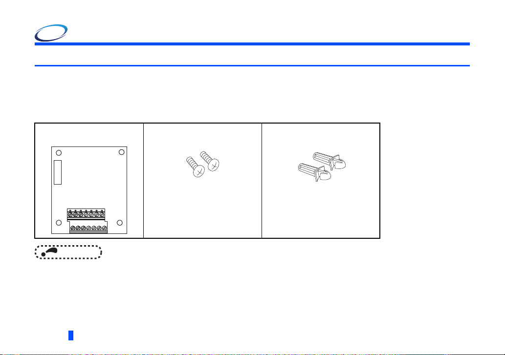
1.1.1 Product confirmation
Check the enclosed items.
Plug-in option
..................................................1
• Connection diagrams in this Instruction Manual appear with the control logic of the input terminals as sink logic, unless
otherwise specified. (For the control logic, refer to the Instruction Manual of the inverter.)
6
PRE-OPERATION INSTRUCTIONS
Mounting screw (M3
...................... 2 (Refer to
8 mm)
page 9
Spacer
)
......................2 (Refer to
page 9
)
Page 7
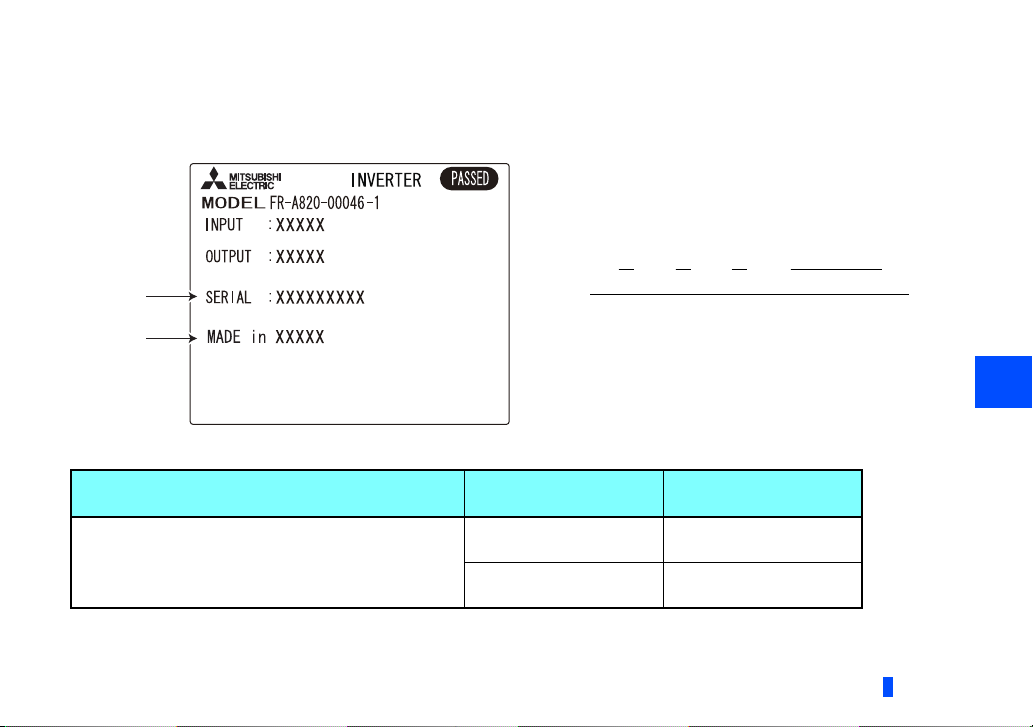
1.1.2 SERIAL number check
SERIAL
number
Country
of origin
The FR-A8APA can be used with the models of inverters listed below which have the following SERIAL number. Check the
SERIAL number indicated on the inverter rating plate or package.
Rating plate example
Symbol Year Month Control number
SERIAL
The SERIAL consists of one symbol, two characters indicating the
production year and month, and six characters indicating the
control number.
The last digit of the production year is indicated as the Year, and
the Month is indicated by 1 to 9, X (October), Y (November), or Z
(December).
FR-A800 series
Model
Country of origin
indication
SERIAL number
1
FR-A820-00046(0.4K) to 04750(90K)
FR-A840-00023(0.4K) to 06830(280K)
FR-A842-07700(315K) to 12120(500K)
FR-A846-00023(0.4K) to 03610(132K)
MADE in Japan 83 or later
MADE in China 84 or later
PRE-OPERATION INSTRUCTIONS
7
Page 8
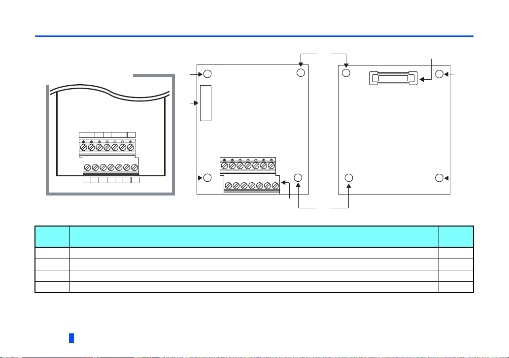
1.2 Component names
Front view Rear view
Terminal layout
EC+ ED+EA+ EB+ ER+
UP UN
EC- ED-EA- EB- ER-
UP UN
(a) (d)
(a)
(a)
(a)
(a)
(c)
(a)
(b)
Symbol Name Description
a Mounting hole Used to fix this product to the inverter by inserting a mounting screw or a spacer. 9
b Terminal block Used to connect the terminals of this product and an encoder. 14
c CON2 connector Pulse output connector. ―
d Board mounted option connector Used to connect this product to the option connector on the inverter. 9
8
PRE-OPERATION INSTRUCTIONS
Refer
to page
Page 9
Spacer
Spacer
Option connector
on the inverter
2 INSTALLATION AND WIRING
2.1 Pre-installation instructions
Check that the inverter's input power and the control circuit power are both OFF.
CAUTION
Do not install or remove this product while the inverter power is ON. Doing so may damage the inverter or this product.
To avoid damage due to static electricity, static electricity in your body must be discharged before you touch this product.
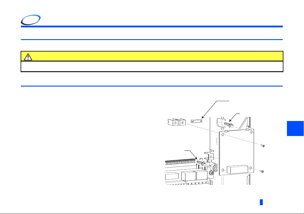
2.2 Installation procedure
(1) Remove the inverter front cover. (Refer to Chapter 2 of
the Instruction Manual (Detailed) of the inverter for
instructions for removing the front cover.)
(2) Insert two spacers into the mounting holes that will not be
filled with mounting screws (see the diagrams on the next
page to identify the holes ).
(3) Fit the board mounted option connector on this product to
the guide of the option connector on the inverter, and
insert the option as far as it goes.
(4) Fasten this product to the inverter using the two mounting
screws through the holes on either side (tightening torque:
0.33 to 0.40 N·m). If the screw holes do not line up, the
connector may not be inserted deep enough. Check the
connector.
2
Example of installation to connector 1
INSTALLATION AND WIRING
9
Page 10
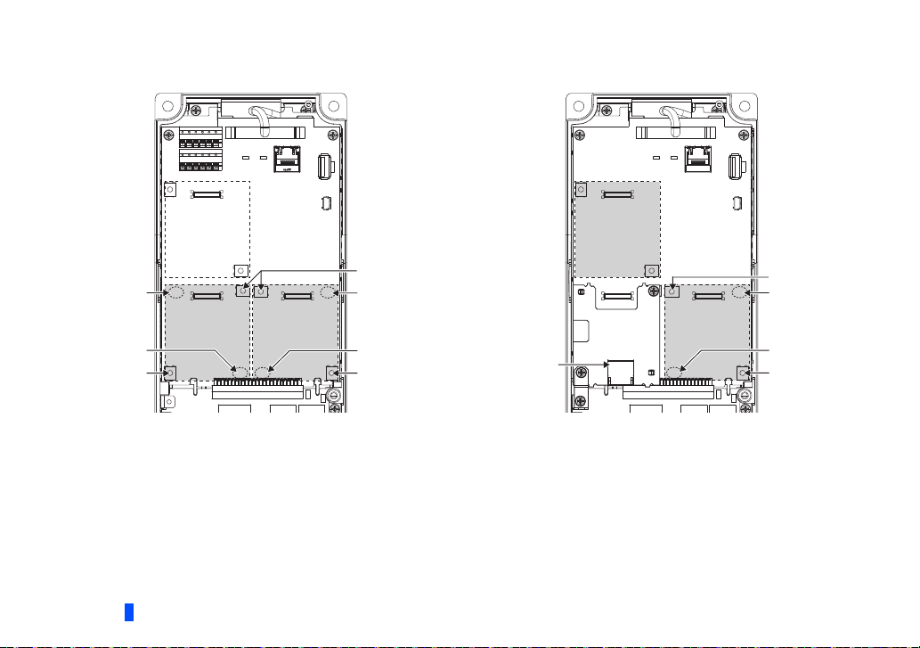
• Insertion positions for screws and spacers
Connector 3
Connector 2 Connector 1
Spacer
Spacer
Mounting screw
Mounting screw
Spacer
Spacer
Mounting screw
Spacer
Spacer
Mounting screw
Mounting screw
Connector 1
Connector 3
Ethernet connector
FR-A800
FR-A800-E
10
Attach the option to connector 1 or 2.
(Do not attach the plug-in option to connector 3.)
INSTALLATION AND WIRING
Attach the option to connector 1 or 3.
Page 11
NOTE
• When installing/removing the plug-in option, hold the sides of the option. Do not press on the parts on the option circuit
board. Stress applied to the parts by pressing, etc. may cause a failure.
• Be careful not to drop mounting screws during the installation or removal of the plug-in option.
• The priorities of vector control compatible plug-in options are defined as follows: FR-A8AL > FR-A8APS > FR-A8APA
> FR-A8APR > FR-A8AP. The vector control compatible plug-in options with lower priority do not function.
• Only one option attached to the option connector with high priority can function at once if more than one option of the
same name are installed together on an inverter. Priority is given to option connectors in descending order (1 to 3),
and options having a lower priority do not function.
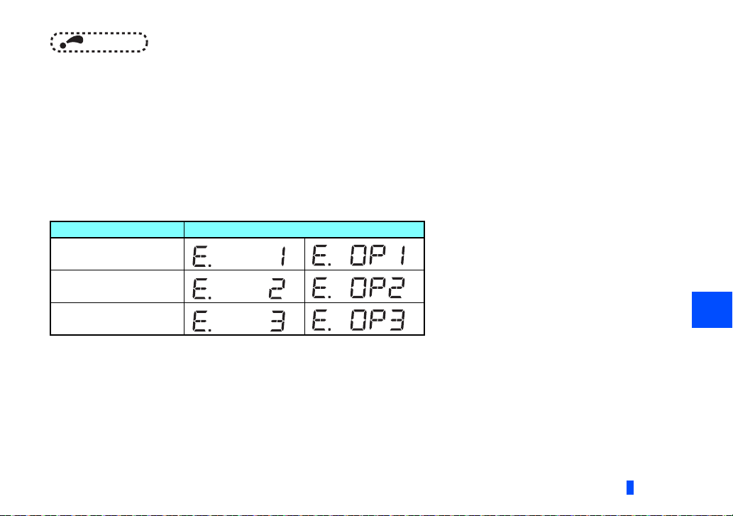
• When the inverter cannot recognize the option unit due to improper installation, etc., or when a fault occurs in the
option or encoder, the protective function (E.1 to E.3 or E.OP1 to E.OP3) is activated and the inverter cannot be
operated. The indication shown (when a fault occurs) depends on the connector used (option connector 1 to 3).
Mounted position Fault indication
Option connector 1
Option connector 2
Option connector 3
• When removing the plug-in option, remove the two screws on either side, and then pull it straight out. Pressure applied
to the option connectors and to the option board may break the option.
INSTALLATION AND WIRING
11
2
Page 12

2.3 Wiring
NOTE
5 mm
Wire
Sleeve
0 to 0.5 mm
(1) Strip the signal wires as shown below. If too much of the wire is stripped, a short circuit may occur with neighboring wires.
If not enough of the wire is stripped, wires may become loose and fall out.
Twist the stripped end of wires to prevent them from fraying. Do not solder it.
Wire strip length
Use appropriate crimp terminals (ferrules, blade terminals, etc.) for these terminal blocks as necessary.
When using the crimp terminal, make sure that the stranded wire do not come out of the terminal.
Unstranded
Wire
Sleeve
wires
Ter min al
screw size
M2
12
0 to 0.5 mm
Damaged
Crumpled tip
Wires are not inserted
into the sleeve
• Crimp terminals commercially available (as of January 2017. The product may be changed without notice.)
Wire size (mm2)
0.3 AI 0,34-6TQ A 0,34-7
0.5 Al 0,5-6WH A 0,5-6
Ferrule part No.
Manufacturer
Phoenix Contact
Co., Ltd.
INSTALLATION AND WIRING
Crimping tool
model No.With insulation sleeve Without insulation sleeve
CRIMPFOX 6
Page 13

(2) Loosen the terminal screw and insert the cable into the terminal.
NOTE
Screw size Tightening torque Cable size Screwdriver
M2 0.22 to 0.25 Nm
• Under-tightening may cause cable disconnection or malfunction. Over-tightening may cause a short circuit or
malfunction due to damage to the screw or unit.
• When wiring the RS-485 terminals on the inverter with the plug-in options installed, be careful not to let RS-485 cables
touch the option circuit boards and the inverter circuit board. This is to prevent a malfunction due to electromagnetic
noises.
0.3 to 0.75 mm
2
Small flat-blade screwdriver
(Tip thickness: 0.4 mm, tip width: 2.5 mm)
CAUTION
After wiring, do not leave wire offcuts in the inverter. Doing so may cause a fault, failure, or malfunction.
2
INSTALLATION AND WIRING
13
Page 14

2.4 Terminals
Ter minal
symbol
UP Encoder power supply (Up)
UN Encoder earth (ground) (0V)
EA+ Incremental sine signal: phase A (A+)
EA- Incremental sine signal: phase A (A-)
EB+ Incremental cosine signal: phase B (B+) For the incremental cosine signal output from the sinusoidal encoder.
EB- Incremental cosine signal: phase B (B-)
ER+ Home position signal: phase R (R+)
ER- Home position signal: phase R (R-)
EC+
EC-
ED+
ED-
14
Magnetic pole position detection sine signal:
phase C (C+)
Magnetic pole position detection sine signal:
phase C (C-)
Magnetic pole position detection cosine signal:
phase D (D+)
Magnetic pole position detection cosine signal:
phase D (D-)
INSTALLATION AND WIRING
Ter mi na l name Description
For the power supply (5 V) for the encoder
For the incremental sine signal output from the sinusoidal encoder
The cosine signal has a phase difference of 90 degrees with respect to
the sine signal (phase A).
For the home position signal output from the sinusoidal encoder
For the sine signal taken from the Z1 track of the sinusoidal encoder
(one period per revolution)
For the cosine signal taken from the Z1 track of the sinusoidal encoder
(one period per revolution)
Page 15

2.5 Encoder
r
Required encoder specifications
Interface
Signal type
Signal period
Permissible speed
The following table shows the supported encoder and cables.
(as of January 2018. The product may be changed without notice.)
Applicable encoder
Recommended cable
Maximum wiring length
Manufacturer
FR-A8APA
Sinusoidal voltage signal (1 Vpp)
Incremental signal (sine/cosine)
Home position signal
Magnetic pole position detection signal (sine/cosine signal taken from the Z1 track, one period per revolution)
2048
Rotation speed of the SinCos encoder interface encoder-mounted shaft: 5800 r/min
The drive shaft and encoder-mounted shaft must be coupled directly or via a belt (with the speed ratio of 1:1)
without any mechanical looseness or slip. Gear changing shafts cannot be applied.
ERN 1387
Cables compatible with the encoder above (manufactured by HEIDENHAIN)
100 m
HEIDENHAIN
circuit board
Terminals
EA+ UNUPEB+ ER+ EC+ ED+
UNUP
EB- ER- EC- ED-
EA-
2
SinCos encode
UN: White/Green
UP: Brown/Green
ED-: Violet
ED+: Yellow
EC-: Pink
EC+: Gray
ER-: Black
ER+: Red
EB-: Red/Black
EB+: Blue/Black
EA-: Yellow/Black
EA+: Green/Black
INSTALLATION AND WIRING
15
Page 16

3 INVERTER FUNCTIONS ENABLED WITH FR-A8APA
NOTE
Parameter for detector
Setting item Parameters for FR-A8APA
Encoder rotation direction Pr.359
Number of detector pulses (Signal period) Pr.369
Encoder signal loss detection enable/disable selection Pr.376
Maximum setting speed of the inverter
When the FR-A8APA is installed, operate the inverter so that the encoder pulse frequency is kept at 100 kHz or lower. If a
speed higher than the maximum speed is set, the speed is clamped at the maximum speed.
• While the motor stops, signal loss may not be detected depending on the motor shaft position. Before starting the
operation, check the wiring.
• The availability of the functions differ according to the specifications of the inverter. Refer to the Instruction Manual of
the Inverter.
• When the motor rotation in the low-speed range (60 r/min or lower) is unstable, check if the encoder cables are
properly connected.
16
INVERTER FUNCTIONS ENABLED WITH FR-A8APA
Page 17

4 ORIENTATION CONTROL
V/FV/FV/F
Magnetic fluxMagnetic fluxMagnetic flux
VectorVectorVector
Use Pr.178 to Pr.189 (input terminal
function selection) to assign the function
to any of terminal.
Refer to the Instruction Manual (Detailed) of
the inverter for details of Pr.178 to Pr.189
(input terminal function selection).
Use Pr.190 to Pr.196 (output terminal
function selection) to assign the function
to any of terminal.
Refer to the Instruction Manual (Detailed) of
the inverter for details of Pr.190 to Pr.196
(output terminal function selection).
Connect the encoder so that there is no
looseness between the motor and motor
shaft. Speed ratio should be 1:1.
Earth (ground) the shield of the encoder
cable to the enclosure using a tool such as
a P-clip.
When a stop position command is input
from outside, a plug-in option FR-A8AX is
necessary. Refer to the Instruction Manual
(Detailed) of the inverter for details of
external stop position command.
This function is used with an encoder installed to the spindle of a machine tool, etc. to allow a rotary shaft to be stopped at the
specified position (oriented).
For the details of the parameters used for orientation control, refer to the Instruction Manual (Detailed) of the inverter.
4.1 Wiring example
Three-phase
MCCB
AC power
supply
Forward rotation start
Reverse rotation start
Orientation command
Contact input common
MC
R/L1
S/L2
T/L3
STF
STR
X22
∗1
SD
ORA
∗2
ORM
∗2
SE
SD
FR-A8AX
∗5
X15
X14
X1
X0
DY
Inverter
FR-A8APA
EA+
EA+
EA-
EA-
EB+
EB+
EB-
EB-
ER+
ER+
ER-
ER-
EC+
EC+
EC-
EC-
ED+
ED+
ED-
ED-
UP
UP
UN
EA+
EA+
EA-
EA-
EB+
EB+
EB-
EB-
ER+
ER+
ER-
ER-
EC+
EC+
EC-
EC-
ED+
ED+
ED-
ED-
UP
UP
UN
U
V
W
E
M
Encoder
ERN 1387
E
∗3
ORIENTATION CONTROL
4
17
U
V
W
Earth
(Ground)
∗4
Page 18

4.2 Terminals
FR-A8AX terminal
Ter minal
symbol
X0 to X15 Digital signal input terminal
DY
Terminal name Description
Data read timing input
signal terminal
Inverter terminal
Ter minal
(signal)
Input X22 Orientation command
Output
18
Terminal (signal) name Application explanation
ORA Orientation complete
ORM Orientation fault
Refer to the Instruction Manual (Detailed) of the inverter for details of Pr.178 to Pr.189 (input terminal function selection) and Pr.190 to
Pr.196 (output terminal function selection).
ORIENTATION CONTROL
Input the digital signal at the relay contact or open collector terminal.
Using Pr.360, speed or position command is selected as the command signal entered.
Used when a digital signal read timing signal is necessary. Data is read only during the DY
signal is on.
By switching the DY signal off, the X0 to X15 data before signal-off is retained.
Used to enter an orientation signal for orientation.
For the terminal used for X22 signal input, set "22" in any of Pr.178 to Pr.189 to assign the
function.
Switched LOW if the orientation has stopped within the in-position zone while the start and
X22 signals are input.
For the terminal used for the ORA signal output, assign the function by setting "27 (positive
logic) or 127 (negative logic)" in any of Pr.190 to Pr.196.
Switched LOW if the orientation has not completed within the in-position zone while the start
and X22 signals are input.
For the terminal used for the ORM signal output, assign the function by setting "28 (positive
logic) or 128 (negative logic)" in any of Pr.190 to Pr.196.
Page 19

4.3 Specifications
Repeated positioning
accuracy
Functions
Holding force after
positioning
Input signal
(contact input)
Output signal
(open collector output)
1.5°
Depends on the load torque, moment of inertia of the load or orientation, creep speed, position loop switching
position, etc.
Orientation, creep speed setting, stop position command selection, DC injection brake start position setting,
creep speed and position loop switch position setting, position shift, orientation in-position, position pulse
monitor, etc.
Under V/F control, Advanced magnetic flux vector control...without servo lock function
Under vector control...with servo lock function
Orientation command, forward and reverse rotation commands, stop position command
Binary signal of maximum 16 bits (when used with the FR-A8AX)
Orientation completion signal, orientation fault signal
4
ORIENTATION CONTROL
19
Page 20

5 ENCODER FEEDBACK CONTROL
V/FV/FV/F
Magnetic fluxMagnetic fluxMagnetic flux
Earth
(Ground)
Inverter
Three-phase
AC power supply
MCCB
R/L1
S/L2
T/L3
U
V
W
U
V
W
E
FR-A8APA
M
STF
STR
SD
10
2
5
MC
Forward rotation start
Reverse rotation start
Contact input common
Frequency setting
potentiometer
∗1
Encoder
ERN 1387
E
∗2
EA+
EA-
EB+
EB-
ER+
ER-
EC+
EC-
ED+
ED-
UP
UN
EA+
EA-
EB+
EB-
ER+
ER-
EC+
EC-
ED+
ED-
UP
EA+
EA-
EB+
EB-
ER+
ER-
EC+
EC-
ED+
ED-
UP
EA+
EA-
EB+
EB-
ER+
ER-
EC+
EC-
ED+
ED-
UP
UN
Connect the encoder so that there is no
looseness between the motor and
motor shaft. Speed ratio should be 1:1.
Earth (ground) the shield of the
encoder cable to the enclosure using a
tool such as a P-clip.
When the FR-A8APA is installed on the FR-A800 series inverter, encoder feedback control can be performed under V/F control
or Advanced magnetic flux vector control.
This controls the inverter output frequency so that the motor speed is constant to the load variation by detecting the motor
speed with the encoder to feed back to the inverter.
For the details of the parameters used for encoder feedback control, refer to the Instruction Manual (Detailed) of the inverter.
5.1 Wiring examples
20
ENCODER FEEDBACK CONTROL
Page 21

5.2 Specifications
Speed variation ratio
Function
0.1% (100% means 3600 r/min)
• Setting of speed feedback range
• Setting of feedback gain
• Setting of encoder rotation direction
5
ENCODER FEEDBACK CONTROL
21
Page 22

6 VECTOR CONTROL
Three-phase
AC power supply
MCCB
Earth
(Ground)
Inverter
Frequency command
Frequency setting
potentiometer
1/2 W1 kΩ
Torque limit
command
( 10 V)
MC
R/L1
S/L2
T/L3
U
V
W
U
V
W
E
FR-A8APA
M
STF
STR
SD
10
2
2
3
1
1
5
(+)
(
-
)
Forward rotation start
Reverse rotation start
Contact input common
∗1
Encoder
ERN 1387
E
∗2
UN
EA+
EA-
EB+
EB-
ER+
ER-
EC+
EC-
ED+
ED-
UP
EA+
EA-
EB+
EB-
ER+
ER-
EC+
EC-
ED+
ED-
UP
UN
When the FR-A8APA is installed on the FR-A800 series inverter, full-scale vector control operation can be performed using a
motor with encoder. (For the details of vector control, refer to the Instruction Manual (Detailed) of the inverter.)
Speed control, torque control, and position control are enabled under vector control for the induction motor.
Speed control and position control are enabled under vector control for the PM motor.
6.1 Wiring examples
Speed control
22
VECTOR CONTROL
Page 23

Torque control (With induction motor only)
MC
2
R/L1
S/L2
T/L3
STF
STR
SD
10
2
5
1
Three-phase
AC power supply
Forward rotation start
Reverse rotation start
Contact input common
Speed limit command
Frequency setting
potentiometer
1/2 W1 kΩ
Torque command
( 10 V)
(+)
(
-
)
MCCB
3
1
Inverter
FR-A8APA
EA+
EA-
EB+
EB-
ER+
ER-
EC+
EC-
ED+
ED-
UP
UN
EA+
EA-
EB+
EB-
ER+
ER-
EC+
EC-
ED+
ED-
UP
UN
U
V
W
E
M
Encoder
ERN 1387
E
∗1
U
V
W
Earth
(Ground)
∗2
VECTOR CONTROL
6
23
Page 24

Position control
Positioning unit
MELSEC iQ-R RD75[]
MELSEC-Q QD75P[ ]N/QD75P[ ]
MELSEC-L LD75P[ ]
Connect the encoder so that there is no looseness between the motor and motor shaft. Speed ratio must be 1:1.
Earth (ground) the shield of the encoder cable to the enclosure using a tool such as a P-clip.
Assign the function using Pr.178 to Pr.184, Pr.187 to Pr.189 (input terminal function selection).
When position control is selected, terminal JOG function is invalid and simple position pulse train input terminal becomes valid.
Assign the function using Pr.190 to Pr.194 (output terminal function selection).
Three-phase
FLS
RLS
DOG
STOP
CLEAR
PULSE F
PULSE R
CLRCOM
PULSE COM
RDYCOM
COM
READY
Torque limit command
( 10 V)
MCCB
AC power
supply
Forward stroke end
Reverse stroke end
Pre-excitation/servo on
Clear signal
Pulse train
Sign signal
24 VDC power supply
Preparation ready signal
(+)
-
)
(
MC
R/L1
S/L2
T/L3
STF
STR
LX
∗3
CLR ∗3
JOG
NP ∗3
PC
SE
RDY ∗5
5
1
∗4
Inverter
FR-A8APA
EA+
EA+
EA-
EA-
EB+
EB+
EB-
EB-
ER+
ER+
ER-
ER-
EC+
EC+
EC-
EC-
ED+
ED+
ED-
ED-
UP
UP
UN
Earth
(ground)
∗2
EA+
EA+
EA-
EA-
EB+
EB+
EB-
EB-
ER+
ER+
ER-
ER-
EC+
EC+
EC-
EC-
ED+
ED+
ED-
ED-
UP
UP
UN
U
V
W
M
E
Encoder
ERN 1387
E
∗1
U
V
W
24
VECTOR CONTROL
Page 25

6.2 Setting procedure of vector control for motor with encoder
Test operation
Perform offline auto tuning for induction motors, or perform offline auto tuning and the encoder position
tuning for PM motors. (Pr.96) (Refer to page 27.)
Configure the initial parameter setting for the applied motor using Pr.998.
When the setting for the PM motor is selected in Pr.998 PM parameter initialization, the vector control for the
motor with an encoder is selected.
"8009": Parameter (rotations per minute) settings for an IPM motor other than MM-CF
"8109": Parameter (frequency) settings for an IPM motor other than MM-CF
"9009": Parameter (rotations per minute) settings for an SPM motor
"9109": Parameter (frequency) settings for an SPM motor
Set Pr.96, and perform tuning.
Set the applied encoder. (Pr.359, Pr.369)
Set Pr.359 Encoder rotation direction and Pr.369 Number of encoder pulses according to the encoder to
be used.
Under position control
•Set Pr.800 again. (Refer to page 26.)
Set the motor. (Pr.9, Pr.71, Pr.80, Pr.81, Pr.83, Pr.84)
Set Pr.71 Applied motor, Pr.9 Rated motor current, Pr.80 Motor capacity, Pr.81 Number of motor poles,
Pr.83 Rated motor voltage, and Pr.84 Rated motor frequency according to the motor specifications.
(Setting "9999 (initial value)" in Pr.80 or Pr.81 selects V/F control.)
Set Pr.702, Pr.706, Pr.707, Pr.724, or Pr.725 as required for the PM motor.
Select vector control (other than position control). (Refer to page 26.)
PM motor
Induction
motor
Follow the following procedure to change the setting for the vector control for the motor with an encoder.
VECTOR CONTROL
6
25
Page 26

NOTE
• For PM motors, after performing offline auto tuning and encoder position tuning, first perform PM parameter
initialization. If parameter initialization is performed after setting other parameters, some of those parameters will be
initialized too. (For the parameters to be initialized, refer to the Instruction Manual (Detailed) of the inverter.)
6.3 Vector control for PM motor with encoder
• With the FR-A8APA, PM motors with an encoder can be driven under vector control. (For the setting of vector control for an
induction motor, refer to the Instruction Manual (Detailed) of the inverter.)
Pr.80
(Pr.453),
Pr.81
Pr.71
(Pr.450)
(Pr.454)
Other than
9999
9999
IPM/SPM
motor
(other than
MM-CF)
―― ―
The setting values of 100 and above are used when the fast-response operation is selected.
The operation for the setting of "0 or 100" is performed when "1, 2, 101, or 102" is set.
The operation for the setting of "4 or 104" is performed when "5 or 105" is set.
Speed control under PM sensorless vector control when the FR-A8APA is not installed.
The operation for the setting of "20 or 110" is performed when "10 to 14, or 111 to 114" is set.
When a PM motor is used, set Pr.80 and Pr.81 according to the motor. Setting "9999" disrupts proper operation.
Pr.800
setting
0, 100
3, 103 Position control ―
4, 104
6, 106
9, 109 ― PM sensorless vector control test operation
20 (initial
value), 110
─
Pr.451
settingControl method Control mode Remarks
Speed control ―
Speed control/position
control switchover
Torque control by variablecurrent limiter control
Speed control ―
20, 110
9999
(initial value)
Vector control
PM sensorless
vector control
The setting value of Pr.800 is used for the second motor.
(PM sensorless vector control (speed control) when Pr.800="9 or 109")
MC signal: ON Position control
MC signal: OFF Speed control
―
26
VECTOR CONTROL
Page 27

6.4 Offline auto tuning
VectorVectorVector
• Offline auto tuning enables the optimal operation of a motor with encoder.
Pr. Name
96
Auto tuning setting/status 0
C110
463
Second motor auto tuning setting/status 0 0, 1, 11, 101
C210
Initial
value
POINTPOINT
• Refer to the Instruction Manual (Detailed) of the inverter to perform offline auto tuning.
• This section explains the specific information of the motor with an encoder.
Setting
range
0 Offline auto tuning disabled.
1 Offline auto tuning enabled (without the motor rotating).
11
101
Offline auto tuning enabled only for motor constant R1 (without the
motor rotating).
Encoder position tuning and
offline auto tuning enabled
(with the motor rotating slightly).
Setting of offline auto tuning for the second motor (refer to Pr.96 for
the setting description.)
Description
PM motor Induction motor
Offline auto tuning enabled
(with the motor rotating).
VECTOR CONTROL
6
27
Page 28

Parameters to be overwritten with the tuning result data after tuning of PM motor
NOTE
Pr. Name
90 (458) Motor constant (R1) Resistance per phase
92 (460) Motor constant (L1)/d-axis inductance (Ld) ― d-axis inductance
93 (461) Motor constant (L2)/q-axis inductance (Lq) ― q-axis inductance
711 (739) Motor Ld decay ratio ― d-axis inductance decay ratio
712 (740) Motor Lq decay ratio ― q-axis inductance decay ratio
859 (860) Torque current/Rated PM motor current ―
96 (463) Auto tuning setting/status
373 Encoder position tuning setting/status ――
1105 Encoder magnetic pole position offset ――
: Tuned, ―: Not tuned
• If the offline auto tuning is started before the encoder position tuning for a PM motor is finished (Pr.1105 = "9999"), the
protective function (E.MP) is activated.
Tuning according to Pr.96 (Pr.463) setting
101 1 11
Description
Encoder position tuning
performing status
Turning data of encoder
position tuning
28
VECTOR CONTROL
Page 29

6.5 Encoder position tuning
NOTE
VectorVectorVector
• Encoder position tuning is required when a PM motor with an encoder is driven. The measured offset value between the
motor home magnetic pole position and the encoder home position is stored. Only encoder position tuning can be
performed when offline auto tuning is not required, such as when the parameters for motor constant are set manually, or
when offline auto tuning is already performed.
Pr. Name
373
C142
1105
C143
Encoder position tuning setting/status 0
Encoder magnetic pole position offset 9999
Initial
value
Before performing encoder position tuning
• Check that the FR-A8APA, a motor, and an encoder are properly connected.
• Check that a motor (single, stop status) is connected. (Check that the motor is not rotated by an external force during
tuning.)
• Check that the mechanical brake is released.
• Check that the vector control (speed control) for the PM motor with an encoder is selected (refer to page 26).
• Encoder position tuning is required when a PM motor is used. (It is disabled when an induction motor is used.)
• When auto tuning is performed while Pr.96 = "101", offline auto tuning and encoder position tuning can be performed
at the same time (refer to page 27).
Setting
• To perform tuning, set Pr.373 = "1".
Setting
range
0 Encoder position tuning disabled.
1 Encoder position tuning enabled.
0 to 4095 Encoder position tuning data set.
9999 No encoder position tuning data.
Description
VECTOR CONTROL
6
29
Page 30

Performing tuning
NOTE
AutoTune 12:34
TUNE
1
--- STOP PU
PREV NEXT
AutoTune 12:34
TUNE
2
STF FWD PU
PREV NEXT
Blinking
AutoTune 12:34
TUNE
Completed
3
STF STOP PU
PREV NEXT
POINTPOINT
• Before tuning, check the monitor display of the PU if the inverter is in the state ready for tuning. If the start command is
turned ON though the inverter is not ready, the motor can start running.
• In the PU operation mode, press / on the operation panel.
In the external operation mode, turn ON the start command (STF signal or STR signal). Tuning will start.
• The motor shaft rotates up to 2 times during tuning.
• The displays/indicator on the operation panel (FR-DU08), the parameter unit (FR-PU07), and the LCD operation panel (FRLU08) will change as shown below while tuning when Pr.373 = "1".
Status Parameter unit (FR-PU07) display
READ:List
TUNE
Setting
1
STOP PU
Operation panel (FR-DU08)
display/indicator
LCD operation panel (FR-LU08) display
During
tuning
Normal
completion
30
VECTOR CONTROL
TUNE
FWD PU
STF
TUNE
COMPLETION
STOP PU
STF
2
3
Page 31

• When encoder position tuning ends, press on the operation panel during PU operation. In the external operation
NOTE
mode, turn OFF the start signal (STF signal or STR signal).
This operation resets encoder position tuning, and the PU's monitor display returns to the normal indication. (Without this
operation, next operation cannot be started.)
• The encoder position tuning data is stored in Pr.1105 until encoder position tuning is performed again. However,
performing all parameter clear resets the tuning data.
• If encoder position tuning has ended in error (see the table below), tuning data has not been set. Perform an inverter reset
and restart tuning.
Pr.373 setting Error cause Corrective actions
8 Forced end Set Pr.373 = "1" and try tuning again.
9 Inverter protective function operation
93 The motor or the encoder is not connected.
• When tuning is ended forcibly by pressing or turning OFF the start signal (STF or STR) during tuning, tuning does
not end properly. (The tuning data have not been set.)
Perform an inverter reset and restart tuning.
• When the protective function (Encoder phase fault (E.EP)) is activated during tuning, check the wiring of the motor and the
encoder, Pr.359 setting, and then perform tuning again.
• When tuning ends properly, the counter value of the offset between the motor home magnetic pole position and the encoder
home position is written in Pr.1105.
Identify and remove the cause of the protective function
activation, and make the setting again.
Check the wiring of the motor and the encoder, the brake
opening, and make the setting again.
VECTOR CONTROL
6
31
Page 32

6.6 Specifications
Speed control range 1:1500 (both driving/regeneration )
Speed control
Torq ue c ont ro l
Position control
Function
Speed variation ratio 0.01% (100% means 3000 r/min)
Speed response 20 Hz (40 Hz during fast-response operation)
Torque control range 1:50
Absolute torque accuracy 10%
Repeated torque accuracy 5%
Repeated positioning accuracy 1.5° (at motor shaft end)
Maximum input pulse frequency 100k pulses/s (Terminal JOG)
Positioning feedback pulse Different depending on the encoder resolution
Electronic gear setting 1/50 to 20
In-position width 0 to 32767 pulses
Error excess 0 to 400k pulses
A regeneration unit (option) is necessary for regeneration.
With online auto tuning (adaptive magnetic flux observer), dedicated motor, rated load
• Setting of speed feedback range
• Setting of feedback gain
32
VECTOR CONTROL
Page 33

APPENDIX
Restricted Use of Hazardous Substances in Electronic and Electrical Products
The mark of restricted use of hazardous substances in electronic and electrical products is applied to the product as follows
based on the “Management Methods for the Restriction of the Use of Hazardous Substances in Electrical and Electronic
Products” of the People's Republic of China.
电器电子产品有害物质限制使用标识要求
环境保护使用期限标识
本产品中所含有的有害物质的名称、含量、含有部件如下表所示。
• 产品中所含有害物质的名称及含量
部件名称
电路板组件 (
如电阻、电容、集成电路、
金属壳体、金属部件
树脂壳体、树脂部件
螺丝、电线
上表依据SJ/T11364的规定编制。
○:表示该有害物质在该部件所有均质材料中的含量均在GB/T26572规定的限量要求以下。
×:表示该有害物质在该部件的至少一种均质材料中的含量超出GB/T26572规定的限量要求。
包括印刷电路板及其构成的零部件,
连接器等)、电子部件
即使表中记载为 ×,根据产品型号,也可能会有 有害物质的含量为限制值以下的情况。
根据产品型号,一部分部件可能不包含在产品 中。
铅(Pb) 汞(Hg) 镉(Cd) 六价铬(Cr(VI)) 多溴联苯(PBB) 多溴二苯醚(PBDE)
有害物质
APPENDIX
33
Page 34

MEMO
34
IB(NA)-0600758ENG-B
Page 35

REVISIONS
*The manual number is given on the bottom left of the back cover.
Print date *Manual number Revision
Jul. 2017 IB(NA)-0600758ENG-A First edition
Feb. 2018 IB(NA)-0600758ENG-B
Addtion
• Compatibility with the FR-A800 series
35
Page 36

INVERTER
HEAD OFFICE: TOKYO BUILDING 2-7-3, MARUNOUCHI, CHIYODA-KU, TOKYO 100-8310, JAPAN
Printed in Japan Specifications subject to change without notice.IB(NA)-0600758ENG-B(1802) MEE
 Loading...