

Mitsubishi FR-A846-00038, FR-A846-00170, FR-A846-00126, FR-A846-00052, FR-A846-00250 Instruction Manual
...
INVERTER
FR-A800
FR-A806 (IP55/UL Type 12 SPECIFICATIONS) INSTRUCTION MANUAL (HARDWARE)
High functionality and high performance
FR-A846-00023(0.4K) to 03610(132K)
INTRODUCTION
INSTALLATION AND WIRING
PRECAUTIONS FOR USE OF
THE INVERTER
PROTECTIVE FUNCTIONS
PRECAUTIONS FOR
MAINTENANCE AND
INSPECTION
SPECIFICATIONS
1
2
3
4
5
6
Thank you for choosing this Mitsubishi inverter.
Warning
Caution
Caution
This Instruction Manual describes handling and cautions about the hardware, such as installation and wiring, for the FR-A806(IP55/
UL Type12 specification product) that are different from the FR-A800.
Information about the software, such as basic operations and parameters, is described in the FR-A800 Instruction Manual (Detailed)
in the CD-ROM enclosed with the product.
In addition to this manual, please read the manuals in the enclosed CD-ROM carefully. Do not use this product until you have a full
knowledge of the equipment, safety information and instructions.
Please forward this Instruction Manual to the end user.
Safety Instructions
Do not attempt to install, operate, maintain or inspect the
product until you have read through this Instruction Manual
(Detailed) and appended documents carefully and can use the
equipment correctly. Do not use this product until you have a
full knowledge of the equipment, safety information and
instructions.
Installation, operation, maintenance and inspection must be
performed by qualified personnel. Here, an expert means a
person who meets all the conditions below.
• A person who took a proper engineering training.
Such training may be available at your local Mitsubishi
Electric office. Contact your local sales office for schedules
and locations.
• A person who can access operating manuals for the
protective devices (e.g. light curtain) connected to the safety
control system. A person who has read and familiarized
himself/herself with the manuals.
In this Instruction Manual (Detailed), the safety instruction
levels are classified into "Warning" and "Caution"
Incorrect handling may cause hazardous
conditions, resulting in death or severe
injury.
Incorrect handling may cause hazardous
conditions, resulting in medium or slight
injury, or may cause only material
damage.
The level may even lead to a serious
consequence according to conditions. Both instruction levels
must be followed because these are important to personal
safety.
Electric Shock Prevention
Warning
While the inverter power is ON, do not remove the front
cover or the wiring cover. Do not run the inverter with the
front cover or the wiring cover removed. Otherwise you may
access the exposed high voltage terminals or the charging
part of the circuitry and get an electric shock.
Even if power is OFF, do not remove the front cover except
for wiring or periodic inspection. You may accidentally
touch the charged inverter circuits and get an electric
shock.
Before wiring or inspection, LED indication of the operation
panel must be switched OFF. Any person who is involved in
wiring or inspection shall wait for at least 10 minutes after
the power supply has been switched OFF and check that
there are no residual voltage using a tester or the like. The
capacitor is charged with high voltage for some time after
power OFF, and it is dangerous.
This inverter must be earthed (grounded). Earthing
(grounding) must conform to the requirements of national
and local safety regulations and electrical code (NEC
section 250, IEC 536 class 1 and other applicable
standards). A neutral-point earthed (grounded) power
supply in compliance with EN standard must be used.
Any person who is involved in wiring or inspection of this
equipment shall be fully competent to do the work.
The inverter must be installed before wiring. Otherwise you
may get an electric shock or be injured.
Setting dial and key operations must be performed with dry
hands to prevent an electric shock. Otherwise you may get
an electric shock.
Do not subject the cables to scratches, excessive
stress,heavy loads or pinching. Otherwise you may get an
electric shock.
Do not change the cooling fan while power is ON. It is
dangerous to change the cooling fan while power is ON.
Do not touch the printed circuit board or handle the cables
with wet hands. Otherwise you may get an electric shock.
When measuring the main circuit capacitor capacity, the DC
voltage is applied to the motor for 1s at powering OFF.
Never touch the motor terminal, etc. right after powering
OFF to prevent an electric shock.
An PM motor is a synchronous motor with high-
performance magnets embedded in the rotor. Motor
terminals holds high-voltage while the motor is running
even after the inverter power is turned OFF. Before wiring
or inspection, the motor must be confirmed to be stopped.
In an application, such as fan and blower, where the motor
is driven by the load, a low-voltage manual motor starter
must be connected at the inverter's output side, and wiring
and inspection must be performed while the motor starter is
open. Otherwise you may get an electric shock.
Fire Prevention
Caution
Inverter must be installed on a nonflammable wall without
holes (so that nobody touches the inverter heatsink on the
rear side, etc.). Mounting it to or near flammable material
may cause a fire.
If the inverter has become faulty, the inverter power must be
switched OFF. A continuous flow of large current may cause
a fire.
Resistors cannot be used. Do not connect a resistor directly
to the DC terminals P/+ and N/-. Doing so could cause a fire.
Be sure to perform daily and periodic inspections as
specified in the Instruction Manual. If a product is used
without any inspection, a burst, breakage, or a fire may
occur.
Injury Prevention
Caution
The voltage applied to each terminal must be the ones
specified in the Instruction Manual. Otherwise burst,
damage, etc. may occur.
The cables must be connected to the correct terminals.
Otherwise burst, damage, etc. may occur.
The polarity (+ and -) must be correct. Otherwise burst,
damage, etc. may occur.
While power is ON or for some time after power-OFF, do not
touch the inverter as it will be extremely hot. Touching
these devices may cause a burn.
Safety Instructions
1

Additional Instructions
The following instructions must be also followed. If the product
is handled incorrectly, it may cause unexpected fault, an injury,
or an electric shock.
Caution
Transportation and Mounting
Any person who is opening a package using a sharp object,
such as a knife and cutter, must wear gloves to prevent
injuries caused by the edge of the sharp object.
The product must be transported in correct method that
corresponds to the weight. Failure to do so may lead to
injuries.
Do not stand or rest heavy objects on the product.
Do not stack the boxes containing inverters higher than the
number recommended.
When carrying the inverter, do not hold it by the front cover;
it may fall off or fail.
During installation, caution must be taken not to drop the
inverter as doing so may cause injuries.
The product must be installed on the surface that
withstands the weight of the inverter.
Do not install the product on a hot surface.
The mounting orientation of the inverter must be correct.
The inverter must be installed on a strong surface securely
with screws so that it will not drop.
Do not install or operate the inverter if it is damaged or has
parts missing.
Foreign conductive objects must be prevented from
entering the inverter. That includes screws and metal
fragments or other flammable substance such as oil.
As the inverter is a precision instrument, do not drop or
subject it to impact.
The ambient temperature must be between -10 and +40°C
(non-freezing). Otherwise the inverter may be damaged.
The ambient humidity must be 95%RH or less (non-
condensing). Otherwise the inverter may be damaged.
(Refer to page 18 for details.)
The storage temperature (applicable for a short time, e.g.
during transit) must be between -20 and +65°C. Otherwise
the inverter may be damaged.
The inverter must be used indoors (without corrosive gas,
flammable gas, oil mist, dust and dirt etc.) Otherwise the
inverter may be damaged.
The inverter must be used at an altitude of 2500 m or less
above sea level, with vibration at 5.9 m/s
Hz (directions of X, Y, Z axes). Otherwise the inverter may
be damaged. (Refer to page 18 for details.)
If halogen-based materials (fluorine, chlorine, bromine,
iodine, etc.) infiltrate into a Mitsubishi product, the product
will be damaged. Halogen-based materials are often
included in fumigant, which is used to sterilize or disinfest
wooden packages. When packaging, prevent residual
fumigant components from being infiltrated into Mitsubishi
products, or use an alternative sterilization or disinfection
method (heat disinfection, etc.) for packaging. Sterilization
of disinfection of wooden package should also be
performed before packaging the product.
Wiring
Do not install a power factor correction capacitor or surge
suppressor/capacitor type filter on the inverter output side.
These devices on the inverter output side may be
overheated or burn out.
The output side terminals (terminals U, V, and W) must be
connected correctly. Otherwise the motor will rotate
inversely.
PM motor terminals (U, V, W) hold high-voltage while the PM
motor is running even after the power is turned OFF. Before
wiring, the PM motor must be confirmed to be stopped.
Otherwise you may get an electric shock.
Never connect an PM motor to the commercial power
supply.
Applying the commercial power supply to input terminals
(U,V, W) of an PM motor will burn the PM motor. The PM
motor must be connected with the output terminals (U, V, W)
of the inverter.
Trial run
Before starting operation, each parameter must be
confirmed and adjusted. A failure to do so may cause some
machines to make unexpected motions.
2.9 m/s2 or less for the FR-A846-01800(55K) or higher.
2
or less, 10 to 55
Warning
Usage
Everyone must stay away from the equipment when the
retry function is set as it will restart suddenly after a trip.
Since pressing a key may not stop output depending
on the function setting status, separate circuit and switch
that make an emergency stop (power OFF, mechanical
brake operation for emergency stop, etc.) must be provided.
OFF status of the start signal must be confirmed before
resetting the inverter fault. Resetting inverter fault with the
start signal ON restarts the motor suddenly.
Do not use an PM motor for an application where the PM
motor is driven by its load and runs at a speed higher than
the maximum motor speed.
Use this inverter only with three-phase induction motors or
with an PM motor. Connection of any other electrical
equipment to the inverter output may damage the
equipment.
Performing pre-excitation (LX signal and X13 signal) under
torque control (Real sensorless vector control) may start
the motor running at a low speed even when the start
command (STF or STR) is not input The motor may run also
at a low speed when the speed limit value = 0 with a start
command input. It must be confirmed that the motor
running will not cause any safety problem before
performing pre-excitation.
Do not modify the equipment.
Do not perform parts removal which is not instructed in this
manual. Doing so may lead to fault or damage of the
product.
2
Safety Instructions

Caution
Usage
The electronic thermal relay function does not guarantee
protection of the motor from overheating. It is
recommended to install both an external thermal and PTC
thermistor for overheat protection.
Do not use a magnetic contactor on the inverter input for
frequent starting/stopping of the inverter. Otherwise the life
of the inverter decreases.
The effect of electromagnetic interference must be reduced
by using a noise filter or by other means. Otherwise nearby
electronic equipment may be affected.
Appropriate measures must be taken to suppress
harmonics. Otherwise power supply harmonics from the
inverter may heat/damage the power factor correction
capacitor and generator.
When driving a 400V class motor by the inverter, the motor
must be an insulation-enhanced motor or measures must
be taken to suppress surge voltage. Surge voltage
attributable to the wiring constants may occur at the motor
terminals, deteriorating the insulation of the motor.
When parameter clear or all parameter clear is performed,
the required parameters must be set again before starting
operations. because all parameters return to their initial
values.
The inverter can be easily set for high-speed operation.
Before changing its setting, the performances of the motor
and machine must be fully examined.
Stop status cannot be hold by the inverter's brake function.
In addition to the inverter’s brake function, a holding device
must be installed to ensure safety.
Before running an inverter which had been stored for a long
period, inspection and test operation must be performed.
Static electricity in your body must be discharged
beforeyou touch the product.
Only one PM motor can be connected to an inverter.
An PM motor must be used under PM sensorless vector
control. Do not use a synchronous motor, induction motor,
or synchronous induction motor.
Do not connect an PM motor in the induction motor control
settings (initial settings). Do not use an induction motor in
the PM sensorless vector control settings. It will cause a
failure.
In the system with an PM motor, the inverter power must be
turned ON before closing the contacts of the contactor at
the output side.
Emergency stop
A safety backup such as an emergency brake must be
provided to prevent hazardous conditions to the machine
and equipment in case of inverter failure.
When the breaker on the inverter input side trips, the wiring
must be checked for fault (short circuit), and internalparts of
the inverter for a damage, etc. The cause of the trip must be
identified and removed before turning ON the power of the
breaker.
When a protective function activates, take an appropriate
corrective action, then reset the inverter, and resume the
operation.
Maintenance, inspection and parts replacement
Do not carry out a megger (insulation resistance) test on the
control circuit of the inverter. It will cause a failure.
Disposal
The inverter must be treated as industrial waste.
General instruction
Many of the diagrams and drawings in the Instruction
Manual show the product without a cover or partially open
for explanation. Never operate the product in this manner.
The cover must be always reinstalled and the instruction in
the Instruction Manual must be followed when operating the
product. For more details on the PM motor, refer to the
Instruction Manual of the PM motor.
Caution
Waterproof and dustproof performances
The inverter is rated with an IPX5
IP5X dustproof rating when the operation panel (FR-DU08-
01), the front cover, the wiring cover, and the cable glands
are securely fixed with screws.
The items enclosed with the inverter such as the Instruction
Manual or CD are not rated with the IPX5 waterproof or IP5X
dustproof ratings.
Although the inverter is rated with the IPX5 waterproof and
IP5X dustproof ratings, it is not intended for use in water.
Also, the ratings do not guarantee protection of the inverter
from needless submersion in water or being washed under
strong running water such as a shower.
Do not pour or apply the following liquids over the inverter:
water containing soap, detergent, or bath additives; sea
water; swimming pool water; warm water; boiling water; etc.
The inverter is intended for indoor
outdoor installation. Avoid places where the inverter is
subjected to direct sunlight, rain, sleet, snow, or freezing
temperatures.
If the operation panel (FR-DU08-01) is not installed, if the
screws of the operation panel are not tightened, or if the
operation panel is damaged or deformed, the IPX5
waterproof performance and the IP5X dustproof
performance are impaired. If any abnormalities are found on
the operation panel, ask for an inspection and repair.
If the screws of the front cover or the wiring cover are not
tightened, if any foreign matter (hair, sand grain, fiber, etc.)
is stuck between the inverter and the gasket, if the gasket is
damaged, or if the front cover or the wiring cover is
damaged or deformed, the IPX5 waterproof performance
and the IP5X dustproof performance are impaired. If any
abnormalities are found on the front cover, wiring cover, or
the gasket of the inverter, ask for an inspection and repair.
Cable glands are important components to maintain the
waterproof and dustproof performances. Be sure to use
cable glands of the recommended size and shape or
equivalent. The standard protective bushes cannot
sufficiently maintain the IPX5 waterproof performance and
the IP5X dustproof performance.
If a cable gland is damaged or deformed, the IPX5
waterproof performance and the IP5X dustproof
performance are impaired. If any abnormalities are found on
the cable glands, ask the manufacturer of the cable glands
for an inspection and repair.
To maintain the waterproof and dustproof performances of
the inverter, daily and periodic inspections are
recommended regardless of the presence or absence of
abnormalities.
IPX5 refers to protection of the inverter functions against water jets from
any direction when about 12.5-liter water
an inside diameter of 6.3 mm from the distance of about 3 m for at least 3
minutes.
IP5X refers to protection of the inverter functions and maintenance of
safety when the inverter is put into a stirring device containing dust of 75
µm or smaller in diameter, stirred for 8 hours, and then removed from the
device.
Water here refers to fresh water at room temperature (5 to 35°C).
Indoor here refers to the environments that are not affected by climate
conditions.
waterproof rating and an
installation and not for
is injected from a nozzle with
Safety Instructions
3

CONTENTS
1 INTRODUCTION 7
1.1 Product checking and accessories 8
1.2 Component names 9
1.3 About the related manuals 10
2 INSTALLATION AND WIRING 11
2.1 Peripheral devices 12
2.1.1 Inverter and peripheral devices ...................................................................................................................... 12
2.1.2 Peripheral devices..........................................................................................................................................14
2.2 Removal and reinstallation of the front cover 15
2.3 Installation of the inverter 18
2.3.1 Inverter installation environment ....................................................................................................................18
2.3.2 Inverter installation ......................................................................................................................................... 20
2.4 Terminal connection diagrams 21
2.5 Main circuit terminals 25
2.5.1 Details on the main circuit terminals............................................................................................................... 25
2.5.2 Terminal layout of the main circuit terminals, wiring of power supply and the motor ..................................... 25
2.5.3 Wiring method ................................................................................................................................................ 26
2.5.4 Applicable cables and the wiring length ......................................................................................................... 29
2.5.5 Earthing (grounding) precautions ................................................................................................................... 31
2.6 Control circuit 32
2.6.1 Details on the control circuit terminals............................................................................................................ 32
2.6.2 Control logic (sink/source) change .................................................................................................................36
2.6.3 Wiring of control circuit ...................................................................................................................................38
2.6.4 Wiring precautions..........................................................................................................................................40
2.6.5 When supplying 24 V external power to the control circuit............................................................................. 41
2.6.6 Safety stop function........................................................................................................................................43
2.7 Operation panel (FR-DU08-01) 45
2.7.1 Differences with the FR-DU08........................................................................................................................ 45
2.7.2 Components of the operation panel (FR-DU08-01) .......................................................................................46
2.7.3 Basic operation of the operation panel...........................................................................................................47
2.8 Communication connectors and terminals 48
2.8.1 PU connector..................................................................................................................................................48
2.8.2 USB connector ............................................................................................................................................... 49
2.8.3 RS-485 terminal block .................................................................................................................................... 51
2.9 Connection of motor with encoder (vector control) 52
2.10 Parameter settings for a motor with encoder 58
2.11 Connection of stand-alone option units 61
2.11.1 Connection of the brake unit (FR-BU2) .......................................................................................................... 61
2.11.2 Connection of the brake unit (FR-BU) ............................................................................................................ 63
4
CONTENTS

2.11.3 Connection of the brake unit (BU type)...........................................................................................................64
2.11.4 Connection of the high power factor converter (FR-HC2) ..............................................................................65
2.11.5 Connection of the power regeneration common converter (FR-CV) ..............................................................66
2.11.6 Connection of the power regeneration converter (MT-RC).............................................................................67
3 PRECAUTIONS FOR USE OF THE INVERTER 69
3.1 Electro-magnetic interference (EMI) and leakage currents 70
3.1.1 Leakage currents and countermeasures ........................................................................................................70
3.1.2 Countermeasures against inverter-generated EMI .........................................................................................72
3.1.3 Built-in EMC filter............................................................................................................................................74
3.2 Power supply harmonics 76
3.2.1 Power supply harmonics.................................................................................................................................76
3.2.2 Harmonic suppression guidelines in Japan ....................................................................................................77
3.3 Installation of a reactor 79
3.4 Power-OFF and magnetic contactor (MC) 80
3.5 Countermeasures against deterioration of the 400 V class motor insulation 81
3.6 Checklist before starting operation 82
3.7 Failsafe system which uses the inverter 84
4 PROTECTIVE FUNCTIONS 87
4.1 Inverter fault and alarm indications 88
4.2 Reset method for the protective functions 88
4.3 Faults history and the list of fault displays 89
5 PRECAUTIONS FOR MAINTENANCE AND
INSPECTION 91
5.1 Inspection item 92
5.1.1 Daily inspection...............................................................................................................................................92
5.1.2 Periodic inspection..........................................................................................................................................92
5.1.3 Daily and periodic inspection ..........................................................................................................................93
5.1.4 Checking the inverter and converter modules ................................................................................................95
5.1.5 Cleaning..........................................................................................................................................................95
5.1.6 Replacement of parts......................................................................................................................................96
5.2 Measurement of main circuit voltages, currents, and powers 116
5.2.1 Measurement of powers ...............................................................................................................................118
5.2.2 Measurement of voltages and use of PT......................................................................................................118
5.2.3 Measurement of currents..............................................................................................................................119
5.2.4 Use of CT and transducer.............................................................................................................................119
5.2.5 Measurement of inverter input power factor .................................................................................................119
CONTENTS
5

5.2.6 Measurement of converter output voltage (across terminals P and N) ........................................................ 119
5.2.7 Measurement of inverter output frequency................................................................................................... 120
5.2.8 Insulation resistance test using megger....................................................................................................... 120
5.2.9 Pressure test ................................................................................................................................................ 120
6 SPECIFICATIONS 121
6.1 Inverter rating 122
6.2 Common specifications 123
6.3 Inverter outline dimension drawings 125
APPENDIX 129
Appendix 1 Differences and compatibility with the FR-A840 ....................................................................... 130
Appendix 2 Instructions for compliance with the EU Directives................................................................... 131
Appendix 3 Instructions for UL and cUL ...................................................................................................... 134
Appendix 4 Instructions for EAC.................................................................................................................. 136
Appendix 5 Restricted Use of Hazardous Substances in Electronic and Electrical Products...................... 137
6
CONTENTS

1 INTRODUCTION
This contents described in this chapter must be read before using this
product.
Always read the instructions before using the equipment.
1.1 Product checking and accessories.........................................8
1.2 Component names....................................................................9
1.3 About the related manuals.......................................................10
<Abbreviations>
Operation panel ..............................Operation panel (FR-DU08-01) and LCD operation panel (FR-LU08-01)
Parameter unit ................................Parameter unit (FR-PU07)
DU ..................................................Operation panel (FR-DU08-01)
PU ..................................................Operation panel (FR-DU08-01) and parameter unit (FR-PU07)
Inverter ...........................................Mitsubishi inverter FR-A800 series (IP55 compatible model)
Vector control compatible option .... FR-A8AP/FR-A8AL/FR-A8APR/FR-A8APS (plug-in option), FR-A8TP
(control terminal option)
Pr. ..................................................Parameter number (Number assigned to function)
PU operation ..................................Operation using the PU (operation panel / parameter unit)
External operation ..........................Operation using the control circuit signals
Combined operation ......................Combined operation using the PU (operation panel / parameter unit) and
External operation
Mitsubishi standard motor .............. SF-JR
Mitsubishi constant-torque motor ... SF-HRCA
Vector control dedicated motor ......SF-V5RU
Mitsubishi IPM motor .....................MM-CF
1
<Trademarks>
• Company and product names herein are the trademarks and registered trademarks of their respective owners.
<Notes on descriptions in this Instruction Manual>
• Connection diagrams in this Instruction Manual suppose that the control logic of the input terminal is the sink
logic, unless otherwise specified. (For the control logic, refer to page 36.)
Harmonic Suppression Guidelines
All the models of the inverters used by specific consumers are covered by "the Harmonic Suppression
Guidelines for Consumers Who Receive High Voltage or Special High Voltage". (For details, refer to page 77.)
INTRODUCTION
7
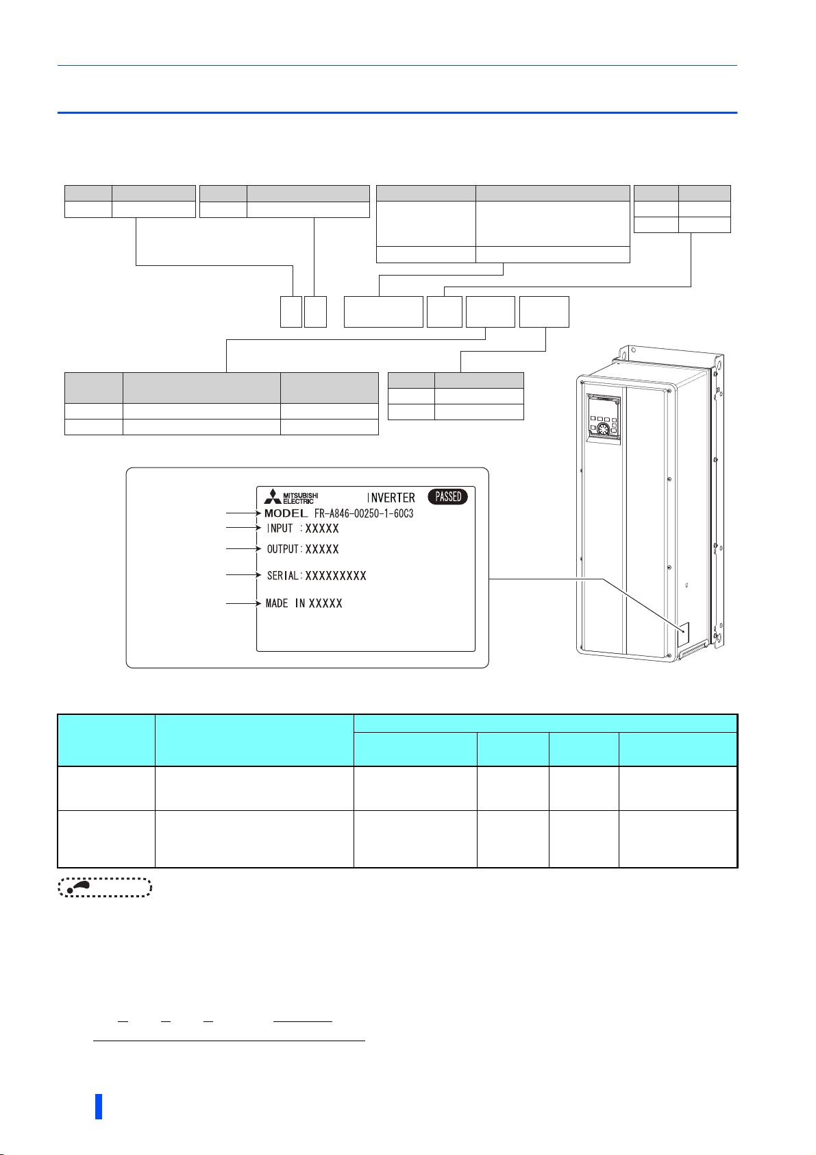
Product checking and accessories
1.1 Product checking and accessories
Unpack the product and check the rating plate and the capacity plate of the inverter to ensure that the model agrees with the
order and the product is intact.
Inverter model
Symbol Voltage class
4
400 V class
Symbol
6
Structure, functionality
IP55 compatible model
Symbol Description
00023 to 03610
0.4K to 132K
Inverter rated current
(SLD rated current of the
A800 standard model) (A)
Inverter ND rated capacity (kW)
Symbol Type∗1
-1
-2
FM
CA
Symbol
-60
-06
F R - A 8 4 6 -
Circuit board coating
(conforming to IEC60721-3-3 3C2/3S2)
With
With
Plated conductor
00250
Without
With
Rating plate
Inverter model
Input rating
Output rating
SERIAL
Country of origin
Specification differs by the type. Major differences are shown in the table below.
-1 -60 C3
Symbol
C2
C3
EMC filter
Built-in C2 filter
Built-in C3 filter
Type Monitor output
FM
(terminal FM
equipped model)
CA
(terminal CA
equipped model)
Terminal FM (pulse train output)
Terminal AM (analog voltage output
(0 to ±10 VDC))
Terminal CA (analog current output
(0 to 20 mADC))
Terminal AM (analog voltage output
(0 to ±10 VDC))
NOTE
• Hereinafter, the inverter model name consists of the applicable motor capacity and the rated current value (SLD rated current
value of the A800 standard model).
(Example) FR-A846-00250(7.5K)
How to read the SERIAL number
Rating plate example
Symbol Year Month Control number
SERIAL
8
INTRODUCTION
Initial setting
Built-in EMC filter
Built-in C2 filter: ON,
Built-in C3 filter: OFF
ON Source logic 50 Hz
The SERIAL consists of one symbol, two characters indicating the production
year and month, and six characters indicating the control number. The last digit
of the production year is indicated as the Year, and the Month is indicated by 1
to 9, X (October), Y (November), or Z (December).
Control
logic
Sink logic 60 Hz
Rated
frequency
Pr.19 Base
frequency voltage
9999 (same as the
power supply voltage)
8888 (95% of the
power supply voltage)
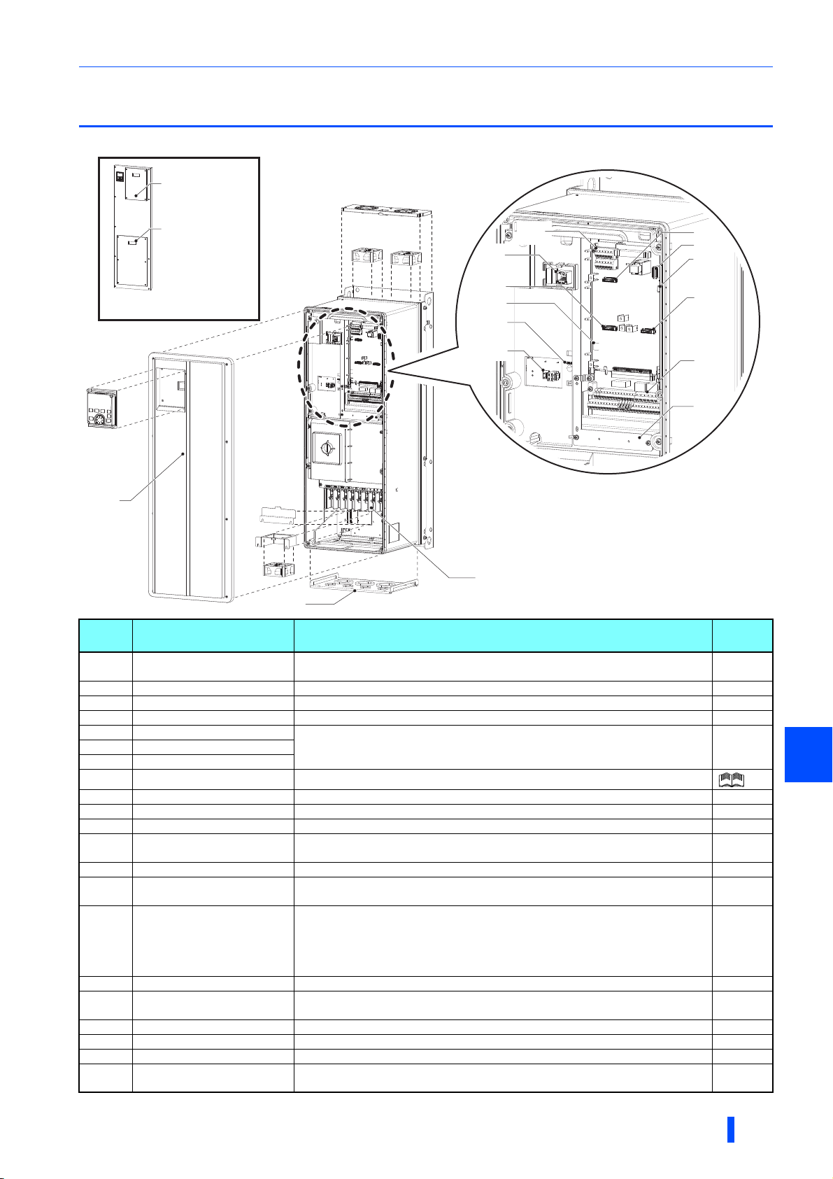
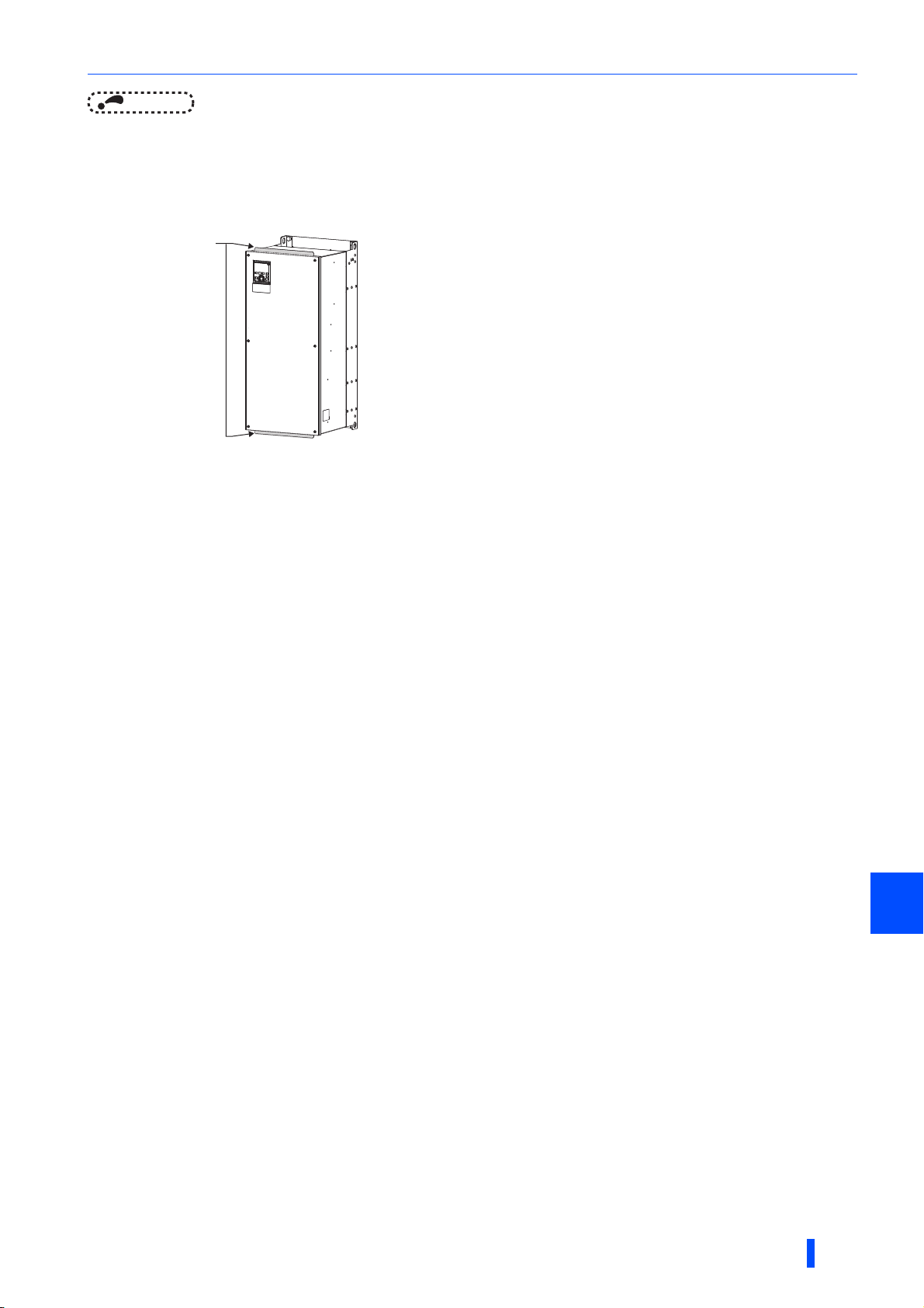
1.2 Component names
Component names are shown below. (Example: FR-A846-00250(7.5K))
Front cover for
control circuit
inspection
Front cover for
main circuit
inspection
(q)
(r)
(a)
(d)
Component names
(g)
(b)
(c)
Front cover of the
FR-A846-01800(55K) or higher
(p)
(o)
(u)
(t)
(s)
(n)
(f)
(h)
(k)
(j)
(m)
Symbol Name Description
(a) PU connector
(b) USB A connector Connects a USB memory device. 49
(c) USB mini B connector Connects a personal computer and enables communication with FR Configurator 2. 49
(d) RS-485 terminals Enables RS-485, MODBUS RTU communication. 51
(e) Plug-in option connector1
(f) Plug-in option connector2
(g) Plug-in option connector3
(h) Voltage/current input switch Selects between voltage and current for the terminal 2 and 4 inputs.
(i) Control circuit terminal block Connects cables for the control circuit. 32
(j) EMC filter ON/OFF connector Turns ON/OFF the EMC filter. 74
(k) Charge lamp Stays ON while the power is supplied to the main circuit. 25
(l)
(m) Main circuit terminal block Connects cables for the main circuit. 25
(n) Wiring cover
(o) Front cover
(p) Operation panel (FR-DU08-01) Operates and monitors the inverter. 46
(q) Fan cover
(r) Cooling fan Cools the inverter. (FR-A846-00250(7.5K) or higher) 97
(s) Internal fan Cools the inverter. 103
(t) Bracket Fixes the internal fan. 103
(u) Protective cover
Metal fitting for earthing
(grounding)
Refer to the FR-A800 Instruction Manual (Detailed)
Connects the operation panel or the parameter unit. This connector also enables
the RS-485 communication.
Connects a plug-in option or a communication option.
Earths (grounds) the shielded wires of the encoder cable, etc. 57
Remove the protective bushes to connect cables. (FR-A846-00470(18.5K) or
lower)
Remove this cover for the installation of the product, installation of a plug-in
(communication) option, RS-485 terminal wiring, switching of the voltage/current
input switch, etc. For the FR-A846-01800(55K) or higher, the front cover for the
control circuit inspection and the front cover for the main circuit inspection can be
individually removed.
Remove this cover for replacement of the cooling fan. (FR-A846-00250(7.5K) or
higher)
Protects the fan to avoid contacting the wiring. (FR-A846-00250(7.5K) to
00470(18.5K))
(e)
(i)
(l)
Refer to
48
Instruction
Manual of
the option
15
15
97
104
page
1
INTRODUCTION
9

About the related manuals
1.3 About the related manuals
The manuals related to FR-A806 are shown below.
Related manuals
Manual name Manual number
FR-A800 Instruction Manual (Detailed) IB-0600503ENG
FR Configurator 2 Instruction Manual IB-0600516ENG
PLC function programming manual IB-0600492ENG
Safety stop function instruction manual BCN-A23228-001
10
INTRODUCTION

2 INSTALLATION AND
WIRING
This chapter explains the "INSTALLATION" and the "WIRING" of this
product.
Always read the instructions before using the equipment.
2.1 Peripheral devices ....................................................................12
2.2 Removal and reinstallation of the front cover........................15
2.3 Installation of the inverter ........................................................18
2.4 Terminal connection diagrams ................................................21
2.5 Main circuit terminals ...............................................................25
2.6 Control circuit ...........................................................................32
2.7 Operation panel (FR-DU08-01).................................................45
2.8 Communication connectors and terminals ............................48
2.9 Connection of motor with encoder (vector control) ..............52
2.10 Parameter settings for a motor with encoder ........................58
2.11 Connection of stand-alone option units .................................61
INSTALLATION AND WIRING
2
11
Peripheral devices
2.1 Peripheral devices
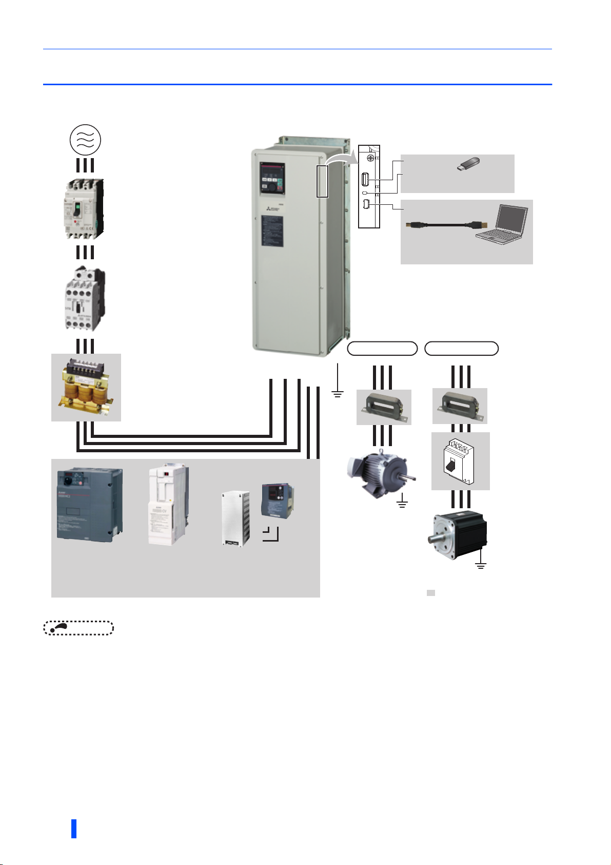
2.1.1 Inverter and peripheral devices
(b) Three-phase AC power supply
(c) Moulded case circuit breaker
(MCCB) or earth leakage current
breaker (ELB), fuse
(d) Magnetic contactor (MC)
(e) AC reactor(FR-HAL)
(a) Inverter
(i) Brake unit
(FR-BU2, FR-BU)
R/L1 S/L2 T/L3
N/-P/+
(Ground)
Earth
∗1
(k) USB connector
IM connection
UVW
USB host
(A connector)
Communication
status indicator
(LED)(USB host)
USB device
(Mini B connector)
PM connection
USB
Personal computer
(FR Configurator 2)
U
VW
(l) EMC filter
(ferrite core)
(FR-BSF01,
FR-BLF)
(n) Contactor
Example)
No-fuse
switch
(DSN type)
(f) High power factor
converter
(FR-HC2)
The figure shows the area when the front cover is removed.
(g) Power regeneration
common converter
(FR-CV)
(h) Power regeneration
converter (MT-RC)
(j) Resistor unit
NOTE
• To prevent an electric shock, always earth (ground) the motor and inverter.
• Do not install a power factor correction capacitor or surge suppressor or capacitor type filter on the inverter's output side.
Doing so will cause the inverter to trip or the capacitor and surge suppressor to be damaged. If any of the above devices is
connected, immediately remove it. When installing a molded case circuit breaker on the output side of the inverter, contact
the manufacturer of the molded case circuit breaker.
• Electromagnetic wave interference
The input/output (main circuit) of the inverter includes high frequency components, which may interfere with the
communication devices (such as AM radios) used near the inverter. In this case, activating the EMC filter may minimize
interference. (Refer to page 74.)
• For details of options and peripheral devices, refer to the respective Instruction Manual.
• A PM motor cannot be driven by the commercial power supply.
• A PM motor is a motor with permanent magnets embedded inside. High voltage is generated at the motor terminals while the
motor is running. Before closing the contactor at the output side, make sure that the inverter power is ON and the motor is
stopped.
PR
P/+
P/+
PR
(FR-BR, MT-BR5)
(m) Induction motor
Earth (Ground)
(o) PM motor
(MM-CF)
Earth (Ground)
: Install these options as required.
12
INSTALLATION AND WIRING

Peripheral devices
Symbol Name Overview
The life of the inverter is influenced by the ambient temperature.
The ambient temperature should be as low as possible within the
permissible range.
Incorrect wiring may lead to damage of the inverter. The control signal
(a) Inverter (FR-A806)
(b) Three-phase AC power supply Must be within the permissible power supply specifications of the inverter. 122
Molded case circuit breaker (MCCB),
(c)
(d) Magnetic contactor (MC)
(e) AC reactor (FR-HAL)
(f) High power factor converter (FR-HC2)
(g)
(h)
(i) Brake unit (FR-BU2, FR-BU
(j) Resistor unit (FR-BR
(k) USB connection
(l)
(m) Induction motor Connect a squirrel-cage induction motor. ―
(n)
(o) PM motor
earth leakage circuit breaker (ELB), or
fuse
Power regeneration common converter
(FR-CV
)
Power regeneration converter
(MT-RC
)
, BU)
, MT-BR5)
Noise filter
(FR-BSF01, FR-BLF)
Contactor
Example) No-fuse switch (DSN type)
Compatible with the FR-A846-01800(55K) or lower.
Compatible with the FR-A846-02160(75K) or higher.
lines must be kept fully away from the main circuit lines to protect them
from noise.
The built-in EMC filter can reduce the noise.
In this inverter, a DC reactor and common mode choke are built in to
suppress harmonics and to improve the power factor.
Must be selected carefully since an inrush current flows in the inverter at
power ON.
Install this to ensure safety.
Do not use this to start and stop the inverter. Doing so will shorten the life
of the inverter.
Install this to suppress harmonics and to improve the power factor.
An AC reactor (FR-HAL) (option) is required when installing the inverter
near a large power supply system (1000 kVA or more). Under such
condition, the inverter may be damaged if you do not use a reactor.
Select a reactor according to the applied motor capacity.
Suppresses the power supply harmonics significantly. Install this as
required.
Provides a large braking capability. Install this as required.
Allows the inverter to provide the optimal regenerative braking capability.
Install this as required.
A USB (Ver. 1.1) cable connects the inverter with a personal computer.
A USB memory device enables parameter copies and the trace function.
Install this to reduce the electromagnetic noise generated from the
inverter. The noise filter is effective in the range from about 0.5 MHz to 5
MHz.
A wire should be wound four turns at maximum.
Connect this for an application where a PM motor is driven by the load
even while the inverter power is OFF. Do not open or close the contactor
while the inverter is running (outputting).
When PM sensorless vector control is selected, a PM motor can be
driven.
Refer
to page
18
21
74
14
80
79
65
66
67
61
49
72
―
―
INSTALLATION AND WIRING
2
13
Peripheral devices
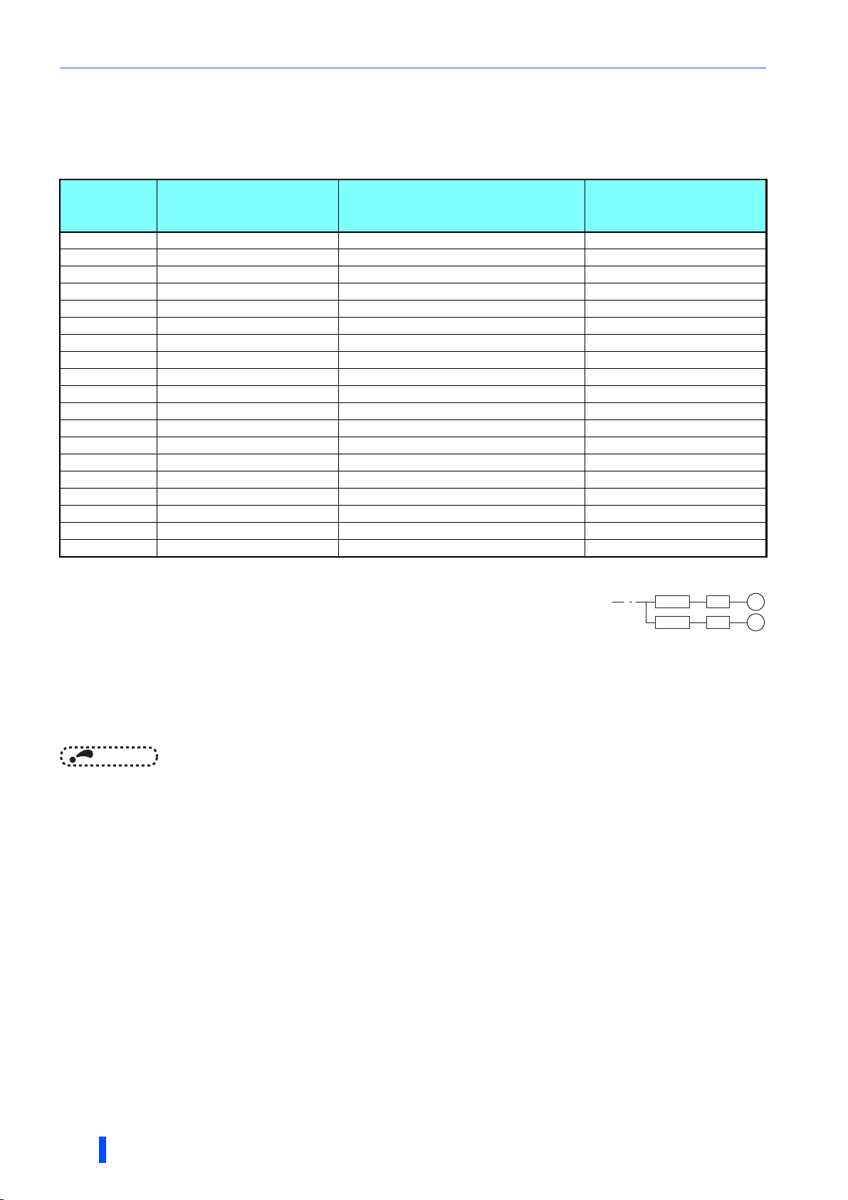
2.1.2 Peripheral devices
Check the model of the inverter you purchased. Appropriate peripheral devices must be selected according to the capacity.
Refer to the table below to prepare appropriate peripheral devices.
Motor output
(kW)
0.4 FR-A846-00023(0.4K) 5 A S-T10
0.75 FR-A846-00038(0.75K) 5 A S-T10
1.5 FR-A846-00052(1.5K) 10 A S-T10
2.2 FR-A846-00083(2.2K) 10 A S-T10
3.7 FR-A846-00126(3.7K) 15 A S-T10
5.5 FR-A846-00170(5.5K) 20 A S-T12
7.5 FR-A846-00250(7.5K) 30 A S-T21
11 FR-A846-00310(11K) 40 A S-T21
15 FR-A846-00380(15K) 50 A S-T21
18.5 FR-A846-00470(18.5K) 60 A S-T35
22 FR-A846-00620(22K) 75 A S-T35
30 FR-A846-00770(30K) 100 A S-T50
37 FR-A846-00930(37K) 100 A S-T50
45 FR-A846-01160(45K) 125 A S-T65
55 FR-A846-01800(55K) 150 A S-T100
75 FR-A846-02160(75K) 200 A S-T100
90 FR-A846-02600(90K) 225 A S-N150
110 FR-A846-03250(110K) 225 A S-N180
132 FR-A846-03610(132K) 350 A S-N220
Assumes the use of a Mitsubishi 4-pole standard motor with the power supply voltage of 400 VAC 50 Hz.
Select an MCCB according to the power supply capacity.
Magnetic contactor is selected based on the AC-1 class. The electrical durability of magnetic contactor is 500,000 times. When the magnetic
Applicable inverter model
Install one MCCB per inverter.
For the use in the United States or Canada, provide the appropriate UL and cUL listed fuse or UL489
molded case
circuit breaker (MCCB) that is suitable for branch circuit protection. (Refer to page 134.)
contactor is used for emergency stops during motor driving, the electrical durability is 25 times.
If using an MC for emergency stop during motor driving, select an MC regarding the inverter input side current as JEM1038-AC-3 class rated
current. When providing an MC on the inverter output side for switching to commercial power supply during general-purpose motor operation,
select an MC regarding the rated motor current as JEM1038-AC-3 class rated current.
Molded case circuit breaker (MCCB)
or earth leakage circuit breaker (ELB)
(NF, NV type)
Input-side magnetic
contactor
MCCB INV
MCCB INV
M
M
14
NOTE
• When the inverter capacity is larger than the motor capacity, select an MCCB and a magnetic contactor according to the
inverter model, and select cables and reactors according to the motor output.
• When the breaker on the inverter's input side trips, check for the wiring fault (short circuit), damage to internal parts of the
inverter etc. The cause of the trip must be identified and removed before turning ON the power of the breaker.
INSTALLATION AND WIRING
Removal and reinstallation of the front cover
Loosen
Loosen
Tighten
Tighten
Tighten
Tighten
(3)
(1)
(5)
(9)
(7)
(4)
(8)
(10)
(6)
(2)
TightenTightenTighten
Tighten
TightenTighten
2.2 Removal and reinstallation of the front
cover
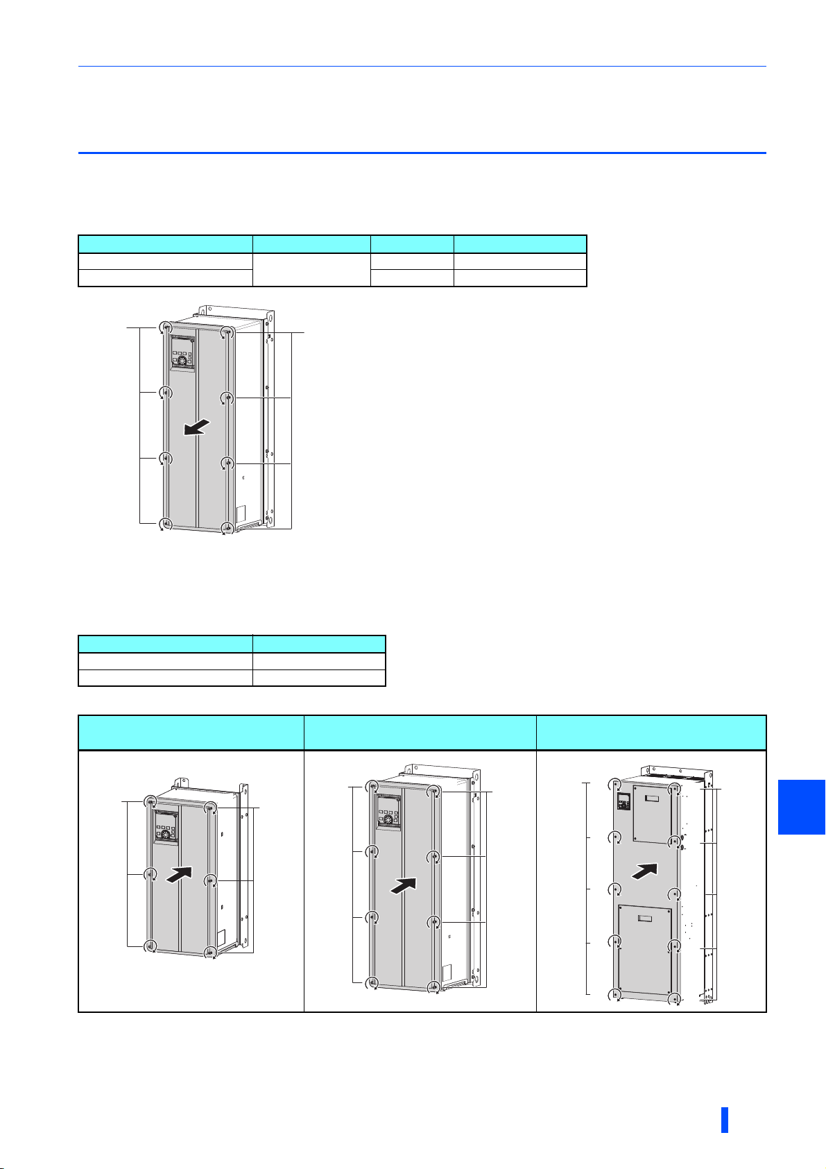
Removal of the front cover
• Remove the front cover installation screws to remove the front cover. (For the FR-A846-00620(22K) to 01160(45K), remove
the operation panel before removing the front cover.)
Inverter Screw type Screw size Screwdriver size
FR-A846-00470(18.5K) or lower
FR-A846-00620(22K) or higher M5 T25
Loosen
Loosen
Hexalobular screw
Loosen
Loosen
M4 T20
Reinstallation of the front cover
• Fix the front cover with the front cover installation screws. (For the FR-A846-00620(22K) to 01160(45K), install the front
cover while the operation panel is removed.)
Inverter Tightening torque
FR-A846-00470(18.5K) or lower 1.4 to 1.9 N·m
FR-A846-00620(22K) or higher 2.8 to 3.6 N·m
Tighten the front cover installation screws in the numerical order in the figure shown below.
FR-A846-00023(0.4K) to 00170(5.5K),
FR-A846-00620(22K) to 01160(45K)
Tighten
Tighten
(1)
(5)
(4)
(3)
(6)
(2)
Tighten
Tighten
FR-A846-00250(7.5K) to 00470(18.5K) FR-A846-01800(55K) to 03610(132K)
Tighten
Tighten
(1)
(5)
(7)
(4)
(3)
(8)
(6)
Tighten
Tighten
2
(2)
INSTALLATION AND WIRING
15
Removal and reinstallation of the front cover
Loosen
Loosen
Tighten
Tighten
Tighten
Tighten
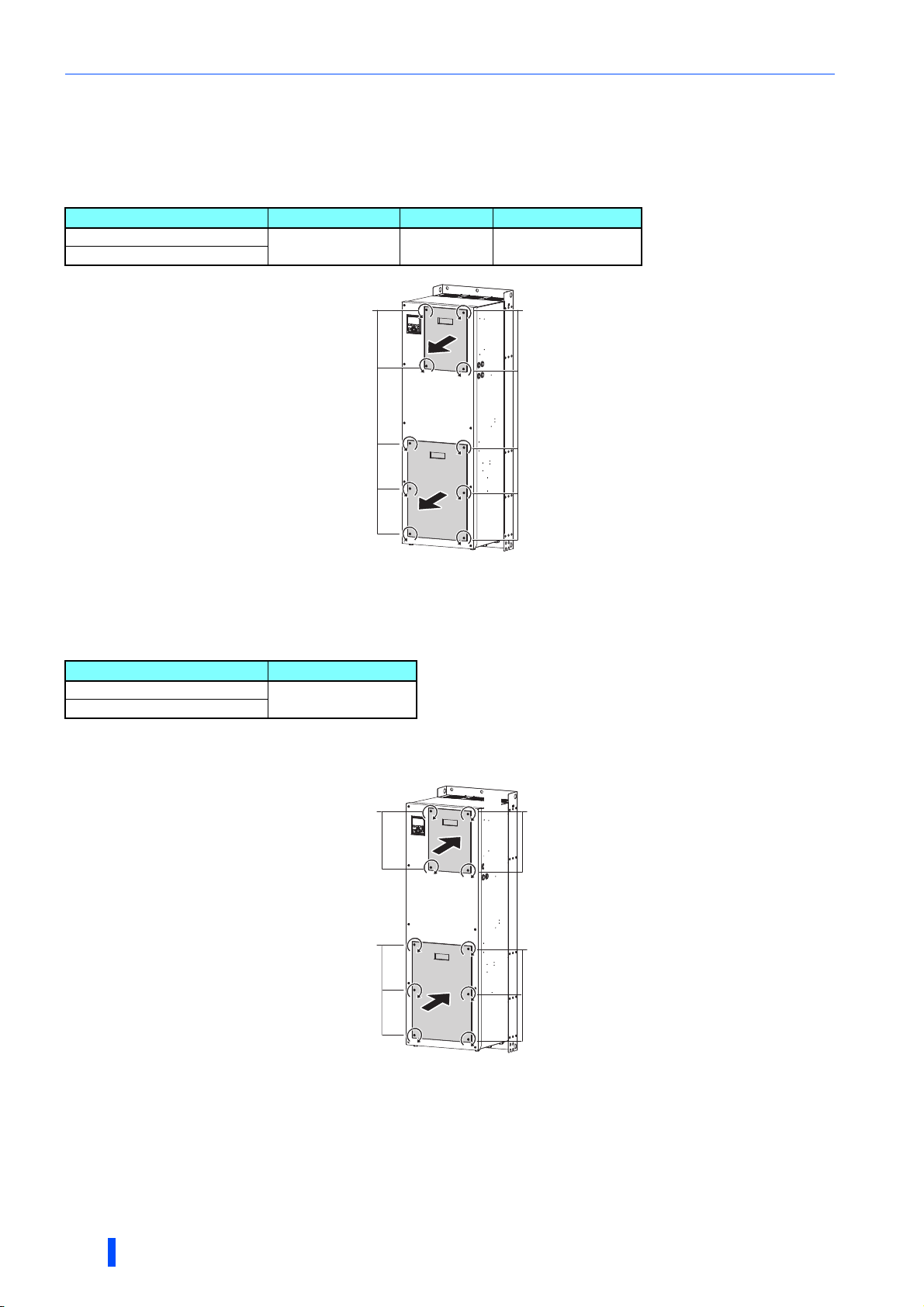
Removal of the front cover for control circuit inspection and the front
cover for main circuit inspection (FR-A846-01800(55K) or higher)
• Remove the installation screws to remove the front cover for control circuit inspection and/or the front cover for main circuit
inspection.
Front cover Screw type Screw size Screwdriver size
For control circuit inspection
For main circuit inspection
Hexalobular screw M5 T25
Loosen
Loosen
Loosen
Loosen
Installation of the front cover for control circuit inspection and the front
cover for main circuit inspection (FR-A846-01800(55K) or higher)
• Fix the covers with the installation screws.
Front cover Tightening torque
For control circuit inspection
For main circuit inspection
To install the front cover for control circuit inspection and/or the front cover for main circuit inspection, tighten the installation
screws in the numerical order in the figure shown below.
2.8 to 3.6 N·m
Tighten
Tighten
Tighten
Tighten
(1)
(4)
(1)
(5)
(4)
(3)
(2)
(3)
(6)
(2)
Tighten
Tighten
Tighten
Tighten
16
INSTALLATION AND WIRING
Removal and reinstallation of the front cover
Flange
NOTE
• When installing the front cover for the FR-A846-00470(18.5K) or lower, fit the connector of the operation panel securely along
the guides of the PU connector. Otherwise, the operation panel connection connector or the PU connector may be damaged.
• For the FR-A846-00620(22K) to 03610(132K), before removing/installing the front cover, always remove the operation panel.
Otherwise, the operation panel connection connector or the PU connector may be damaged.
• When removing/installing the front cover of the FR-A846-00620(22K) to 01160(45K), always hold the front cover at the flange
sections. Otherwise, the front cover may fall off, resulting in damage or injuries.
Flange
Flange
• Before installing the front cover, check the waterproof gasket to make sure that it is not damaged. If it is damaged, contact the
nearest Mitsubishi FA center.
• Securely install the front cover to fit the waterproof gasket closely. Do not let the waterproof gasket get stuck between the
front cover edge and the inverter. Otherwise, water may get into the inverter. Also, do not let any foreign matter get stuck
between the waterproof gasket and the front cover.
• Keep the waterproof gasket of the inverter clean. Otherwise, water may get into the inverter. If there is any dirt on the gasket,
make sure to remove it.
• Fully make sure that the front cover is installed securely. Always tighten the mounting screws of the front cover.
INSTALLATION AND WIRING
2
17
Installation of the inverter
2.3 Installation of the inverter
An inverter unit uses many semiconductor devices. To ensure higher reliability and long period of operation, operate the
inverter in the ambient environment that completely satisfies the equipment specifications.
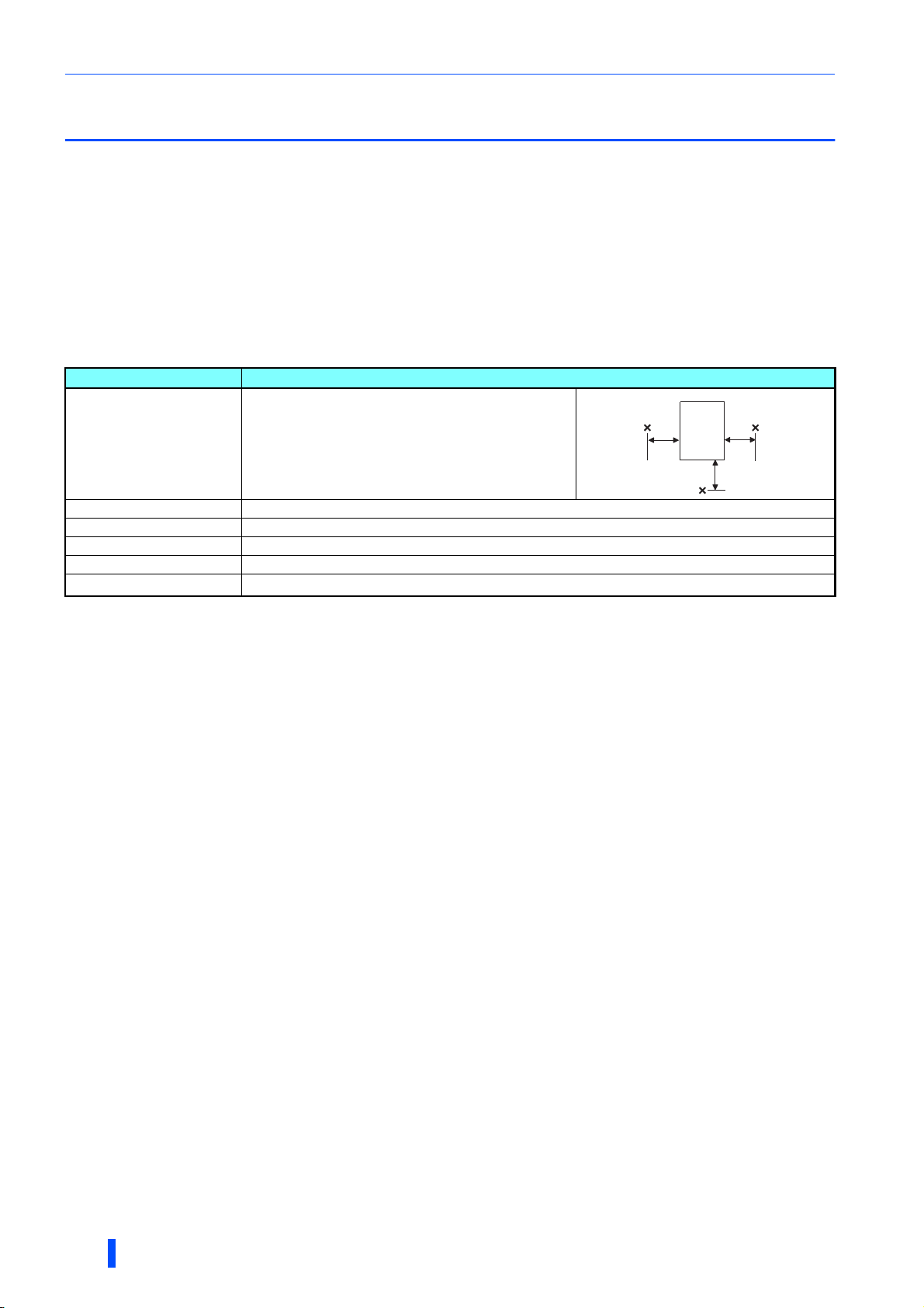
2.3.1 Inverter installation environment
The following table lists the standard specifications of the inverter installation environment. Using the inverter in an
environment that does not satisfy the conditions deteriorates the performance, shortens the life, and causes a failure. Refer to
the following points, and take adequate measures.
Standard environmental specifications of the inverter
Item Description
Measurement
position
Ambient temperature -10 to +40°C (non-freezing)
5 cm 5 cm
Inverter
Measurement
position
Ambient humidity 95% RH or less (non-condensing)
Storage temperature -20 to +65°C
Atmosphere Indoors (free from corrosive gas, flammable gas, oil mist, dust and dirt)
Altitude Maximum 1,000 m above sea level.
Vibration
Temperature applicable for a short time, e.g. in transit.
For the installation at an altitude above 1,000 m (3280.80 feet) up to 2,500 m (8202 feet), derate the rated current 3% per 500 m (1640.40 feet).
2.9 m/s
2
or less for the FR-A846-01800(55K) or higher.
5.9 m/s
2
or less at 10 to 55 Hz (directions of X, Y, Z axes)
5 cm
Temperat ure
The permissible ambient temperature of the inverter is between -10°C and +40°C. Always operate the inverter within this
temperature range. Operation outside this range will considerably shorten the service lives of the semiconductors, parts,
capacitors and others. Take the following measures to keep the ambient temperature of the inverter within the specified range.
(a) Measures against high temperature
• Ventilate the room.
• Install the inverter in an air-conditioned electric chamber.
• Block direct sunlight.
• Provide a shield or similar plate to avoid direct exposure to the radiated heat and wind of a heat source.
• Ventilate the area around the inverter well.
(b) Measures against low temperature
• Provide a heater around the inverter.
• Do not power OFF the inverter. (Keep the start signal of the inverter OFF.)
(c) Sudden temperature changes
• Select an installation place where temperature does not change suddenly.
• Avoid installing the inverter near the air outlet of an air conditioner.
• If temperature changes are caused by opening/closing of a door, install the inverter away from the door.
18
INSTALLATION AND WIRING

Installation of the inverter
Humidity
Operate the inverter within the ambient air humidity of usually 45 to 90%. Too high humidity will pose problems of reduced
insulation and metal corrosion. On the other hand, too low humidity may cause a spatial electrical breakdown.
The insulation distance defined in JEM1103 "Control Equipment Insulator" is humidity of 45 to 85%.
(a) Measures against high humidity
• Provide dry air into the room from outside.
• Use a dehumidifier.
(b) Measures against low humidity
Air with proper humidity can be blown into the room from outside. Also when installing or inspecting the unit, discharge your
body (static electricity) beforehand, and keep your body away from the parts and patterns.
(c) Measures against condensation
Condensation may occur if frequent operation stops change the in-room temperature suddenly or if the outside air
temperature changes suddenly.
Condensation causes such faults as reduced insulation and corrosion.
• Take the measures against high humidity in (a).
• Do not power OFF the inverter. (Keep the start signal of the inverter OFF.)
Dust, dirt, oil mist
Dust and dirt will cause faults such as poor contacts, reduction in insulation and cooling effect due to accumulation of
moisture-absorbed dust and dirt, and equipment internal temperature rise due to a clogged ventilation filter in the room where
the equipment is installed. In an atmosphere where conductive powder floats, dust and dirt will cause such faults as
malfunction, deteriorated insulation and short circuit in a short time.
Since oil mist will cause similar conditions, it is necessary to take adequate measures.
Countermeasure
• Purge air.
Pump clean air from outside to make the in-enclosure air pressure higher than the outside air pressure.
Corrosive gas, salt damage
If the inverter is exposed to corrosive gas or to salt near a beach, the printed board patterns and parts will corrode or the
relays and switches will result in poor contact.
In such a place, take the countermeasures described in "Dust, dirt, oil mist" above.
Explosive, flammable gases
As the inverter is non-explosion proof, it must be contained in an explosion-proof enclosure. In places where explosion may
be caused by explosive gas, dust or dirt, an enclosure cannot be used unless it structurally complies with the guidelines and
has passed the specified tests. This makes the enclosure itself expensive (including the test charges). The best way is to
avoid installation in such places and install the inverter in a non-hazardous place.
High altitude
Use the inverter at an altitude of within 1000 m. For the installation at an altitude above 1,000 m (3280.80 feet) up to 2,500 m
(8202 feet), derate the rated current 3% per 500 m (1640.40 feet).
If it is used at a higher place, it is likely that thin air will reduce the cooling effect and low air pressure will deteriorate dielectric
strength.
Vibration, impact
The vibration resistance of the inverter is up to 5.9 m/s2 (2.9 m/s2 or less for the FR-A846-01800(55K) or higher) at 10 to 55
Hz frequency and 1 mm amplitude for the directions of X, Y, Z axes. Applying vibration and impacts for a long time may loosen
the structures and cause poor contacts of connectors, even if those vibration and impacts are within the specified values.
Especially when impacts are applied repeatedly, caution must be taken because such impacts may break the installation feet.
2
Countermeasure
• Strengthen the structure to prevent the installation surface from resonance.
• Install the inverter away from the sources of the vibration.
INSTALLATION AND WIRING
19
Installation of the inverter
Fix six positions for the FR-A846-01800(55K) or higher.
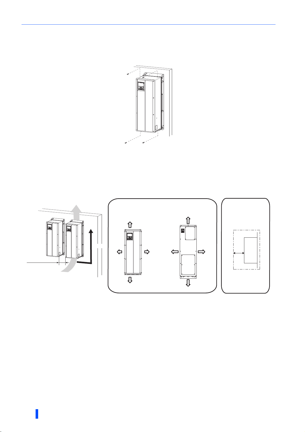
2.3.2 Inverter installation
Inverter placement
• Install the inverter on a strong flat surface securely with screws.
• Leave enough clearances and take cooling measures.
• Avoid places where the inverter is subjected to direct sunlight, high temperature and high humidity.
• Install the inverter on a nonflammable wall surface.
• For heat dissipation and maintenance, keep clearance between the inverter and the other devices. The clearance below
the inverter is required as a wiring space, and the clearance above the inverter is required as a heat dissipation space.
Clearances (side)
Inverter
5 cm
FR-A846-01800(55K) or lower
Vertical
Allow clearance.
For the FR-A846-00126(3.7K) or lower, allow 1 cm or more clearance.
10 cm
5 cm5 cm
10 cm
Clearances (front)
FR-A846-02160(75K) or higher
10 cm
20 cm
10 cm
20 cm
Installation orientation of the inverter
Install the inverter on a wall as specified. Do not mount it horizontally or in any other way.
Above the inverter
Heat is blown up from inside the inverter by the small fan built in the unit. Any equipment placed above the inverter should be
heat resistant.
20
INSTALLATION AND WIRING
Terminal connection diagrams
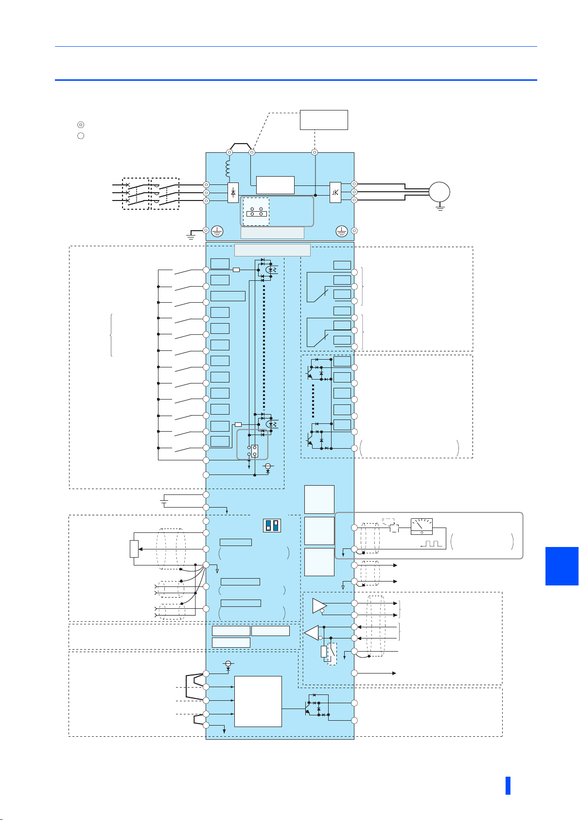
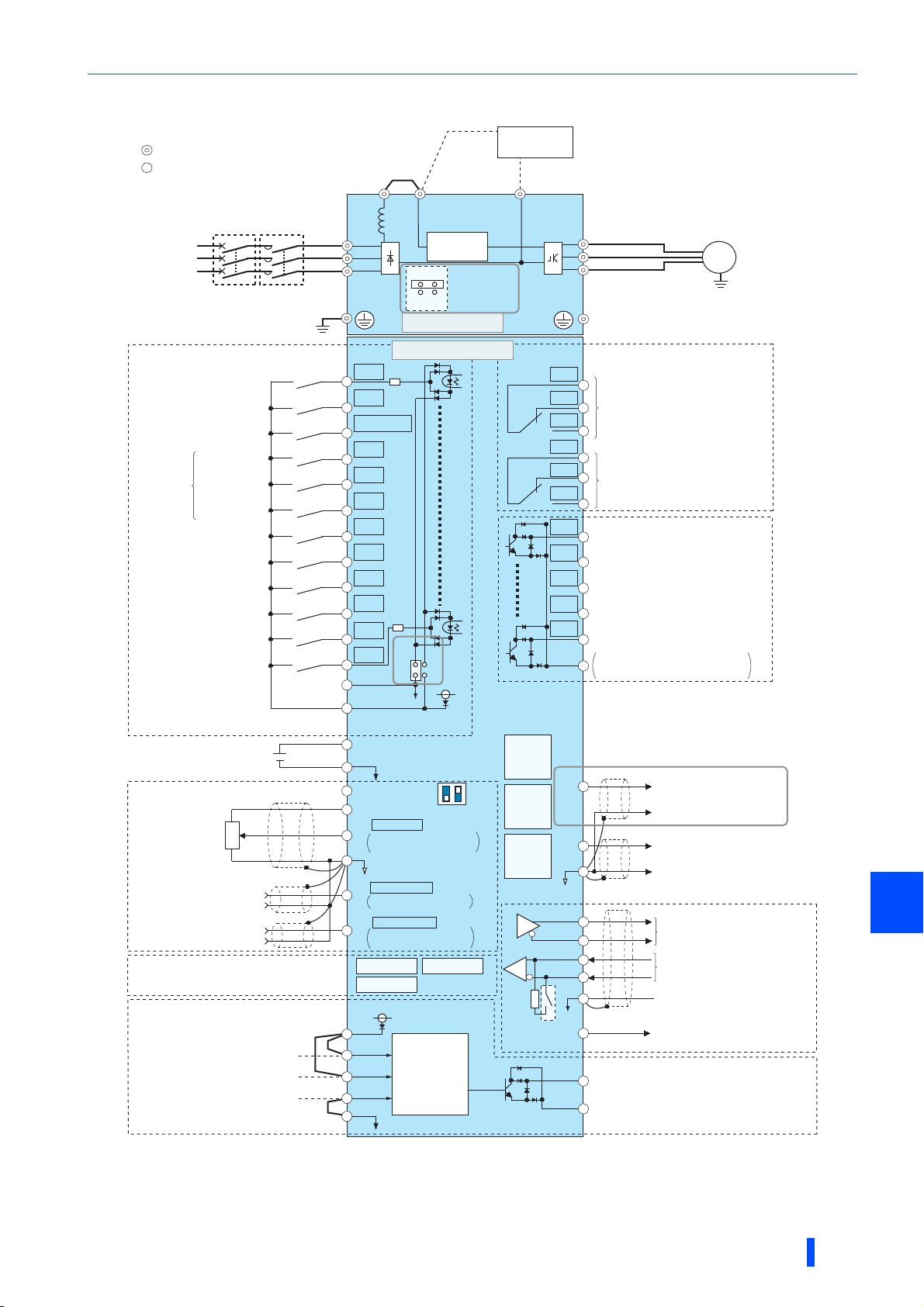
2.4 Terminal connection diagrams
FM type
Sink logic
Main circuit terminal
Control circuit terminal
Jumper
Brake unit
(Option)
MCCB
Three-phase
AC power
supply
Control input signals
(No voltage input allowed)∗1
Forward rotation start
Reverse rotation start
Start self-holding selection
High speed
Multi-speed
selection
Second function selection
Terminal 4 input selection
(Current input selection)
Selection of automatic restart
Contact input common
(Common for external power supply transistor)
Frequency setting signals (Analog)
Frequency setting
potentiometer
1/2W1kΩ∗4
Connector for plug-in option connection
Safety stop signal
Safety stop input (Channel 1)
Safety stop input (Channel 2)
Middle speed
Low speed
Jog operation
Output stop
after instantaneous
power failure
24V external power
supply input
Common terminal
Auxiliary
input
Terminal 4 input
(Current input)
Safety stop input common
MC
Earth
(Ground)
Reset
24VDC power supply
3
2
1
(+)
(-)
(+)
(-)
Shorting
wire
P1
Reactor
R/L1
S/L2
T/L3
Inrush current
limit circuit
ON
OFF
Main circuit
Control circuit
STF
STR
STP(STOP)
RH
RM
RL
JOG
∗2
RT
MRS
RES
AU
CS
SD
PC
+24
SD
10E(+10V)
10(+5V)
DC0 to 5V
2
DC0 to 10V
DC0 to 20mA
5
(Analog common)
DC0 to ±10V
1
DC0 to ±5V selectable
DC4 to 20mA
4
DC0 to 5V
DC0 to 10V
connector 1 connector 2
connector 3
24V
PC
S1
S2
SIC
SD
SINK
SOURCE
Voltage/current
∗3
input switch
ON
OFF
2
Initial value
selectable
Initial value
Initial value
selectable
Output shutoff
circuit
EMC filter
ON/OFF
connecter
24V
4
∗3
∗3
∗3
N/-P/+
∗9
PU
connector
USB A
connector
USB
mini B
connector
Terminating
resistor
U
V
W
C1
B1
Relay output 1
(Fault output)
A1
C2
B2
Relay output 2
A2
RUN
Running
SU
Up to frequency
IPF
Instantaneous
power failure
OL
Overload
FU
Frequency detection
SE
Open collector output common
Sink/source common
F/C
(FM)
∗7
SD
AM
TXD+
TXD-
RXD+
RXD-
GND
(SG)
VCC
So
SOC
5
Calibration
resistor ∗8
Safety monitor output
Safety monitor output common
Motor
M
Earth (Ground)
Relay output∗5
Open collector output∗6
+-
(+)
Analog signal output
(0 to ±10VDC)
(-)
Data
transmission
Data
reception
GND
5V
(Permissible load current 100mA)
Indicator
(Frequency meter, etc.)
Moving-coil type
1mA full-scale
RS-485 terminals
2
INSTALLATION AND WIRING
21

Terminal connection diagrams
The function of these terminals can be changed with the input terminal assignment (Pr.178 to Pr.189). (Refer to the FR-A800 Instruction Manual
(Detailed).)
Terminal JOG is also used as a pulse train input terminal. Use Pr.291 to choose JOG or pulse.
Terminal input specifications can be changed by analog input specification switchover (Pr.73, Pr.267). To input a voltage, set the voltage/current
input switch OFF. To input a current, set the voltage/current input switch ON. Terminals 10 and 2 are also used as a PTC input terminal. (Pr.561)
(Refer to the FR-A800 Instruction Manual (Detailed).)
It is recommended to use 2 W 1 k when the frequency setting signal is changed frequently.
The function of these terminals can be changed with the output terminal assignment (Pr.195, Pr.196). (Refer to the FR-A800 Instruction Manual
(Detailed).)
The function of these terminals can be changed with the output terminal assignment (Pr.190 to Pr.194). (Refer to the FR-A800 Instruction
Manual (Detailed).)
The terminal FM can be used to output pulse trains as open collector output by setting Pr.291.
Not required when calibrating the scale with the operation panel.
Do not change the initially set ON (enabled) position of the EMC filter ON/OFF connector in the case of the inverter with a built-in C2 filter. The
Class C2 compatibility condition is not satisfied with the EMC filter OFF. The FR-A846-00250(7.5K)-C2 to FR-A846-00470(18.5K)-C2 are not
provided with the EMC filter ON/OFF connector. The EMC filter is always ON.
NOTE
• To prevent a malfunction due to noise, keep the signal cables 10 cm (3.94 inches) or more away from the power cables. Also,
separate the main circuit cables at the input side from the main circuit cables at the output side.
• After wiring, wire offcuts must not be left in the inverter.
Wire offcuts can cause an alarm, failure or malfunction. Always keep the inverter clean.
When drilling mounting holes in a wall or the side of the enclosure etc., take caution not to allow chips and other foreign
matters to enter the inverter.
• Set the voltage/current input switch correctly. Incorrect setting may cause a fault, failure or malfunction.
22
INSTALLATION AND WIRING
CA type
Source logic
Main circuit terminal
Control circuit terminal
Jumper
Brake unit
(Option)
Terminal connection diagrams
MCCB
Three-phase
AC power
supply
Control input signals
(No voltage input allowed)∗1
Forward rotation start
Reverse rotation start
Start self-holding selection
High speed
Multi-speed
selection
Second function selection
Terminal 4 input selection
(Current input selection)
Selection of automatic restart
after instantaneous power failure
Common for external power
Contact input common
Middle speed
Low speed
Jog operation
Output stop
Reset
supply transistor
24VDC power supply
MC
Earth
(Ground)
Reactor
R/L1
S/L2
T/L3
STF
STR
STP(STOP)
RH
RM
RL
JOG
RT
MRS
RES
AU
CS
SD
PC
P1
Inrush current
limit circuit
ON
EMC filter
ON/OFF
connecter
OFF
Main circuit
Control circuit
∗2
SINK
SOURCE
24V
N/-P/+
U
V
W
∗7
C1
B1
Relay output 1
(Fault output)
A1
C2
B2
Relay output 2
A2
RUN
Running
SU
Up to frequency
IPF
Instantaneous
power failure
OL
Overload
FU
Frequency detection
SE
Open collector output common
Sink/source common
Open collector output∗6
Motor
M
Earth (Ground)
Relay output∗5
24V external power
supply input
Common terminal
Frequency setting signals (Analog)
Auxiliary
input
3
2
1
(+)
(-)
(+)
(-)
Shorting
wire
Frequency setting
potentiometer
1/2W1kΩ∗4
Terminal 4 input
(Current input)
Connector for plug-in option connection
Safety stop signal
Safety stop input (Channel 1)
Safety stop input (Channel 2)
Safety stop input common
+24
SD
10E(+10V)
10(+5V)
DC0 to 5V
2
DC0 to 10V
DC0 to 20mA
5
(Analog common)
DC0 to ±10V
1
DC0 to ±5V selectable
DC4 to 20mA
4
DC0 to 5V
DC0 to 10V
connector 1 connector 2
connector 3
PC
S1
S2
SIC
SD
∗3
ON
OFF
selectable
24V
Output shutoff
circuit
Voltage/current
input switch
42
Initial value
selectable
Initial value
Initial value
∗3
∗3
∗3
PU
connector
USB A
connector
USB
mini B
connector
TXD+
TXD-
RXD+
RXD-
Terminating
resistor
F/C
(CA)
AM
5
GND
(SG)
VCC
So
Safety monitor output
SOC
Safety monitor output common
(+)
Analog current output
(0 to 20mADC)
(-)
(+)
Analog signal output
(DC0 to ±10V)
(-)
RS-485 terminals
Data
transmission
Data
reception
GND
5V
(Permissible load current 100mA)
2
INSTALLATION AND WIRING
23

Terminal connection diagrams
The function of these terminals can be changed with the input terminal assignment (Pr.178 to Pr.189). (Refer to the FR-A800 Instruction Manual
(Detailed).)
Terminal JOG is also used as a pulse train input terminal. Use Pr.291 to choose JOG or pulse.
Terminal input specifications can be changed by analog input specification switchover (Pr.73, Pr.267). To input a voltage, set the voltage/current
input switch OFF. To input a current, set the voltage/current input switch ON. Terminals 10 and 2 are also used as a PTC input terminal. (Pr.561)
(Refer to the FR-A800 Instruction Manual (Detailed).)
It is recommended to use 2 W 1 k when the frequency setting signal is changed frequently.
The function of these terminals can be changed with the output terminal assignment (Pr.195, Pr.196). (Refer to the FR-A800 Instruction Manual
(Detailed).)
The function of these terminals can be changed with the output terminal assignment (Pr.190 to Pr.194). (Refer to the FR-A800 Instruction
Manual (Detailed).)
Do not change the initially set ON (enabled) position of the EMC filter ON/OFF connector in the case of the inverter with a built-in C2 filter. The
Class C2 compatibility condition is not satisfied with the EMC filter OFF. The FR-A846-00250(7.5K)-C2 to FR-A846-00470(18.5K)-C2 are not
provided with the EMC filter ON/OFF connector. The EMC filter is always ON.
NOTE
• To prevent a malfunction due to noise, keep the signal cables 10 cm or more away from the power cables. Also, separate the
main circuit cables at the input side from the main circuit cables at the output side.
• After wiring, wire offcuts must not be left in the inverter.
Wire offcuts can cause an alarm, failure or malfunction. Always keep the inverter clean.
When drilling mounting holes in a wall or the side of the enclosure etc., take caution not to allow chips and other foreign
matters to enter the inverter.
• Set the voltage/current input switch correctly. Incorrect setting may cause a fault, failure or malfunction.
24
INSTALLATION AND WIRING
Main circuit terminals
2.5 Main circuit terminals
2.5.1 Details on the main circuit terminals
Terminal
symbol
R/L1,
S/L2,
T/L3
U, V, W Inverter output Connect these terminals to a three-phase squirrel cage motor or a PM motor. —
P/+, N/- Brake unit connection
P/+, P1 —
Terminal name Terminal function description
Connect these terminals to the commercial power supply.
AC power input
Earth (ground) For earthing (grounding) the inverter chassis. This must be earthed (grounded). 31
Do not connect anything to these terminals when using the high power factor
converter (FR-HC2) or the power regeneration common converter (FR-CV).
Connect the brake unit (FR-BU2, FR-BU, BU), power regeneration common
converter (FR-CV), power regeneration converter (MT-RC), high power factor
converter (FR-HC2), or DC power supply (under DC feeding mode).
Do not remove the jumper across terminals P/+ and P1 except for connecting the
power regeneration common converter (FR-CV) or the high power factor converter
(FR-HC2).
Refer to
page
—
61
—
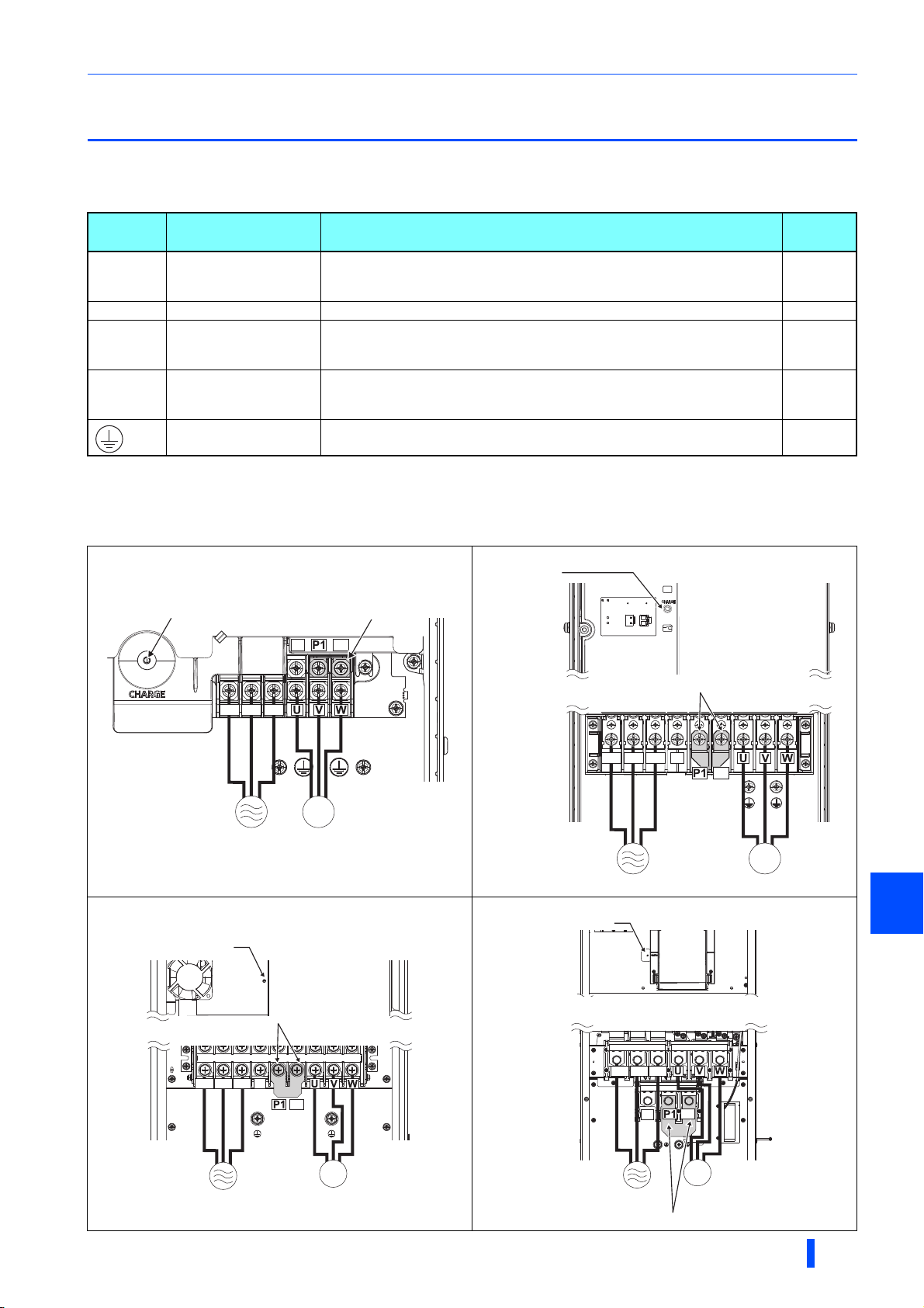
2.5.2 Terminal layout of the main circuit terminals,
wiring of power supply and the motor
FR-A846-00023(0.4K) to FR-A846-00170(5.5K)
P/+
N/-
JumperCharge lamp
FR-A846-00250(7.5K) to FR-A846-00470(18.5K)
Charge lamp
R/L1
T/L3
S/L2
M
MotorPower supply
FR-A846-00620(22K) to FR-A846-01160(45K)
Charge lamp
Jumper
S/L2 T/L3
N/-
P/+
R/L1
Jumper
T/L3
S/L2 T/L3
N/-
N/-
P/+
P/+
R/L1
S/L2
Power supply
FR-A846-01800(55K) to FR-A846-03610(132K)
Charge lamp
R/L1
M
Motor
2
M
MotorPower supply
Power supply
INSTALLATION AND WIRING
M
Motor
Jumper
25
Main circuit terminals
Loosen
Example of the FR-A846-00250(7.5K)
Loosen
NOTE
• Make sure the power cables are connected to the R/L1, S/L2, and T/L3. (Phase need not be matched.) Never connect the
power cable to the U, V, and W of the inverter. Doing so will damage the inverter.
• Connect the motor to U, V, and W. The phase need to be matched.
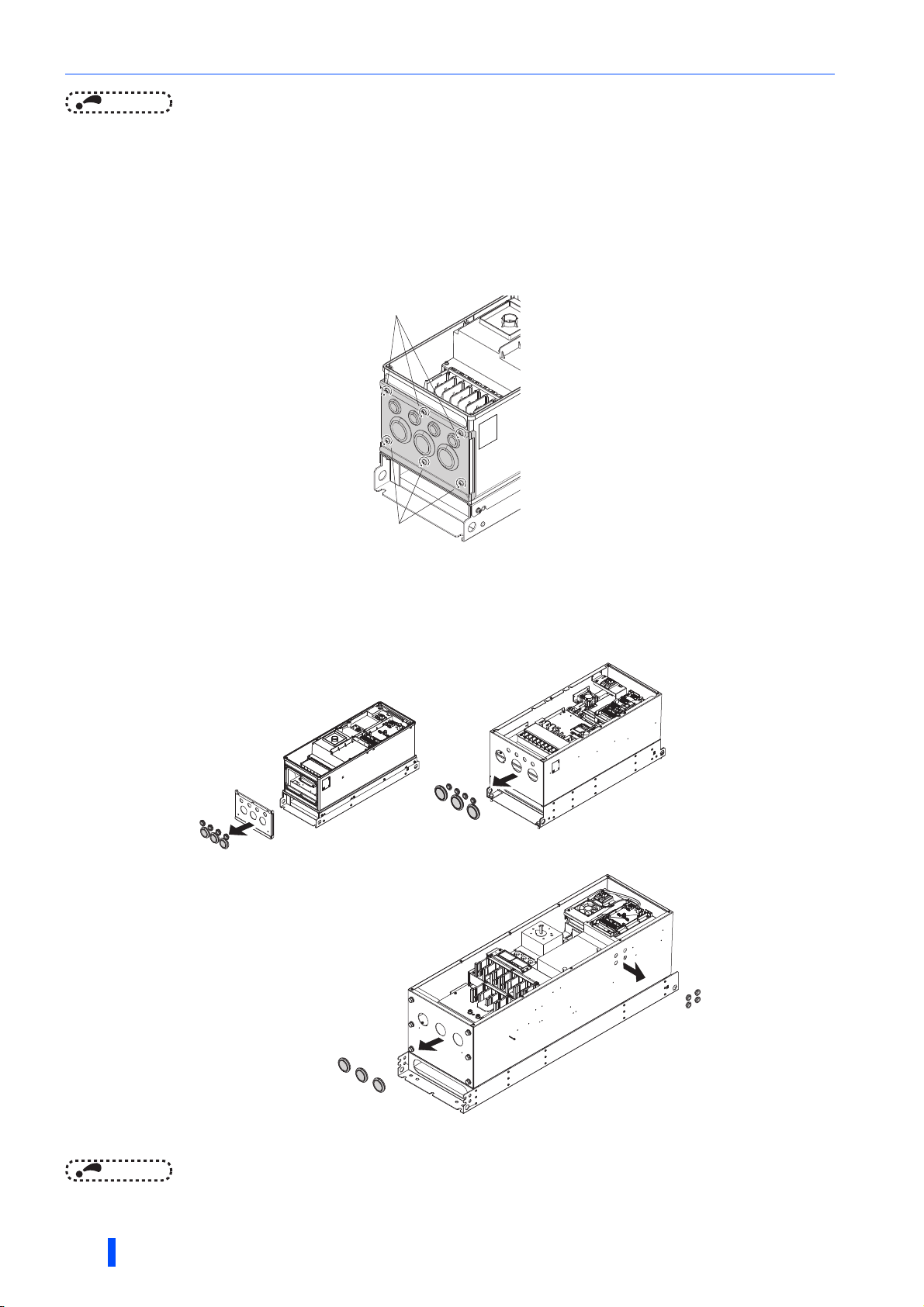
2.5.3 Wiring method
(1) Remove the front cover of the inverter. (Refer to page 15)
(2) For the FR-A846-00470(18.5K) or lower, remove the wiring cover installation screws (hexalobular screws, screw size:
M5, screwdriver size: T25, tightening torque: 2.8 to 3.6 N·m) to remove the wiring cover.
Loosen
Loosen
Loosen
Loosen
Example of the FR-A846-00250(7.5K)
Example of the FR-A846-00250(7.5K)
(3) For the FR-A846-00470(18.5K) or lower, remove the protective bushes from the wiring cover.
For the FR-A846-00620(22K) to FR-A846-01160(45K), remove the protective bushes from the bottom of the inverter.
For the FR-A846-01800(55K) or higher, remove the protective bushes from the bottom and the side of the inverter.
(Do not remove the protective bushes from the holes that are not used for wiring of cables.)
FR-A846-00023(0.4K) to FR-A846-00470(18.5K) FR-A846-00620(22K) to FR-A846-01160(45K)
NOTE
• For the FR-A846-01800(55K) or higher, do not remove the screws on the bottom of the inverter. The IPX5 waterproof
performance may be impaired.
26
INSTALLATION AND WIRING
FR-A846-01800(55K) to FR-A846-03610(132K)
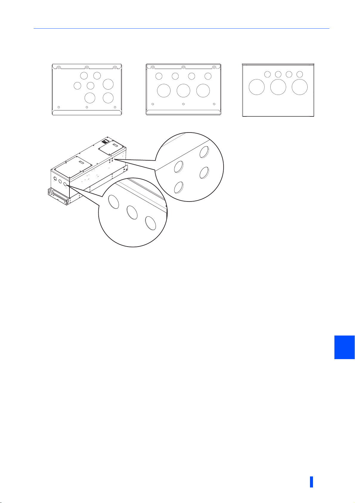
(4) Fix the cables using a cable gland and a nut, according to the diameter of the holes.
(b)
(c)
(d)
(a)
(a)
(a)
(a)
For the details such as hole diameters and recommended cable glands, refer to the following table.
FR-A846-00250(7.5K) to 00470(18.5K)FR-A846-00023(0.4K) to 00170(5.5K) FR-A846-00620(22K) to 01160(45K)
(a) (a)
(a) (a)
(b) (d)
FR-A846-01800(55K) to 03610(132K)
(c)
(a)
(a) (a) (a)
(b) (c) (d)
Main circuit terminals
(a)
(a) (a) (a)
(b) (c) (d)
INSTALLATION AND WIRING
2
27
Main circuit terminals
Inverter
capacity
FR-A84600023(0.4K) to
00170(5.5K)
FR-A84600250(7.5K) to
00470(18.5K)
FR-A84600620(22K) to
02600(90K)
FR-A84603250(110K),
03610(132K)
EMC-compliant cable gland
General-purpose cable gland
Symbol
(a)
(b)
(d)
(a)
(b)
(d)
(a)
(b)
(d)
(a)
(b)
(d)
Recommended
layout example
Control circuit
wiring
AC power input
wiring
Brake unit
connection wiring
Inverter output
wiring
Control circuit
wiring
AC power input
wiring
Brake unit
connection wiring
Inverter output
wiring
Control circuit
wiring
AC power input
wiring
Brake unit
connection wiring
Inverter output
wiring
Control circuit
wiring
AC power input
wiring
Brake unit
connection wiring
Inverter output
wiring
Hole
diameter
(mm)
20.3
32.3
20.3
40.4
20.3
63
20.3
63
Recommended cable gland
(Manufactured by LAPP KABEL)
SKINTOP MS-SC-M20 53112630
SKINTOP MS-M20 53112020
SKINTOP MS-SC-M32 53112650
SKINTOP MS-M32 BRUSH 53112677
SKINTOP MS-M32 53112040
SKINTOP MS-SC-M20 53112630
SKINTOP MS-M20 53112020
SKINTOP MS-SC-M40 53112660
SKINTOP MS-M40 BRUSH 53112678
SKINTOP MS-M40 53112050
SKINTOP MS-SC-M20 53112630
SKINTOP MS-M20 53112020
SKINTOP MS-M63 BRUSH 53112680
SKINTOP MS-M63 53112070
SKINTOP MS-SC-M20 53112630
SKINTOP MS-M20 53112020
SKINTOP MS-M63 BRUSH PLUS 53112681
SKINTOP MS-M63 PLUS 53112080
(5) For the FR-A846-00470(18.5K) or lower, install the wiring cover.
(6) Connect cables to the terminals of the inverter.
(7) Install the front cover to the inverter. (Refer to page 15)
Recommended nut
(Manufactured by
LAPP KABEL)
SKINDICHT SM-M20 52103020
SKINDICHT SM-M32 52103040(c)
SKINDICHT SM-M32 52103020
SKINDICHT SM-M40 52103050(c)
SKINDICHT SM-M20 52103020
SKINDICHT SM-M63 52103070(c)
SKINDICHT SM-M20 52103020
SKINDICHT SM-M63 52103070(c)
Caution
Always use a waterproof cable gland (IP55 or higher) for the hole from which the protective bush is
removed because water may get into the inverter.
28
INSTALLATION AND WIRING

Main circuit terminals
2.5.4 Applicable cables and the wiring length
Select a recommended cable size to ensure that the voltage drop will be 2% or less.
If the wiring distance is long between the inverter and motor, the voltage drop in the main circuit wires will cause the motor
torque to decrease especially at a low speed.
The following table indicates a selection example for the wiring length of 20 m.
• 400 V class (440 V input power supply (with 150% rated current for one minute))
cable
Cable gauge
AWG/MCM
R/L1,
S/L2,
U, V,
T/L3
PVC cables, etc. (mm2)
W
R/L1,
S/L2,
T/L3
U, V,
W
(grounding)
Applicable
inverter
model
FR-A846-[ ]
00023(0.4K) to
00126(3.7K)
00170(5.5K) M4 1.5 2-4 2-4 2 2 3.5 3.5 12 14 2.5 2.5 4
00250(7.5K) M6 4.4 5.5-6 5.5-6 3.5 3.5 3.5 3.5 12 12 4 4 4
00310(11K) M6 4.4 5.5-6 5.5-6 5.5 5.5 5.5 5.5 10 10 6 6 10
00380(15K) M6 4.4 5.5-6 5.5-6 5.5 5.5 8 5.5 10 10 6 6 10
00470(18.5K) M6 4.4 8-6 8-6 8 8 14 8 8 8 10 10 16
00620(22K) M6 4.4 14-6 14-6 14 14 22 14 6 6 16 16 16
00770(30K) M6 4.4 22-6 22-6 22 22 22 14 4 4 25 25 16
00930(37K) M8 7.8 22-8 22-8 22 22 22 14 4 4 25 25 16
01160(45K) M8 7.8 38-8 38-8 38 38 38 22 2 2 50 50 25
01800(55K) M10 14.7 60-10 60-10 60 60 60 22 1/0 1/0 50 50 25
02160(75K) M10 14.7 60-10 60-10 60 60 60 22 1/0 1/0 50 50 25
02600(90K) M10 14.7 60-10 60-10 60 60 80 22 3/0 3/0 50 50 25
03250(110K) M10 14.7 80-10 80-10 80 80 80 38 3/0 3/0 70 70 35
03610(132K) M10 14.7 100-10 100-10 100 100 100 38 4/0 4/0 95 95 50
Terminal
screw
size
M4 1.5 2-4 2-4 2 2 2 2 14 14 2.5 2.5 2.5
For the FR-A846-01800(55K) or lower, it is the gauge of a cable with the continuous maximum permissible temperature of 75°C (HIV cable (600
V grade heat-resistant PVC insulated wire), etc.). It assumes a surrounding air temperature of 50°C or lower and the wiring distance of 20 m or
shorter.
For the FR-A846-02160(75K) or higher, it is the gauge of the cable with the continuous maximum permissible temperature of 90°C or higher.
(LMFC (heat resistant flexible cross-linked polyethylene insulated cable), etc.). It assumes a surrounding air temperature of 50°C or lower.
For the FR-A846-01160(45K) or lower, it is the gauge of a cable with the continuous maximum permissible temperature of 75°C (THHW cable).
It assumes a surrounding air temperature of 40°C or lower and the wiring distance of 20 m or shorter.
For the FR-A846-01800(55K) or higher, it is the gauge of a cable with the continuous maximum permissible temperature of 90°C (THHN cable).
It assumes a surrounding air temperature of 40°C or lower. (Selection example for use mainly in the United States.)
For the FR-A846-01160(45K) or lower, it is the gauge of a cable with the continuous maximum permissible temperature of 70°C (PVC cable). It
assumes a surrounding air temperature of 40°C or lower and the wiring distance of 20 m or shorter.
For the FR-A846-01800(55K) or higher, it is the gauge of a cable with the continuous maximum permissible temperature of 90°C (XLPE cable).
It assumes a surrounding air temperature of 40°C or lower. (Selection example for use mainly in Europe.)
The terminal screw size indicates the size of terminal screw for R/L1, S/L2, T/L3, U, V, W, P/+, N/-, P1, and a screw for earthing (grounding).
Tightening
torque
N·m
Crimping
terminal
R/L1,
S/L2,
T/L3
U, V,
W
HIV cables, etc. (mm2)
R/L1,
S/L2,
T/L3
U, V,
W
P/+
Earthing
(grounding)
Earthing
cable
2
The line voltage drop can be calculated by the following formula:
Line voltage drop [V]=
× wire resistance[mΩ/m] × wiring distance[m] × current[A]
1000
Use a larger diameter cable when the wiring distance is long or when it is desired to decrease the voltage drop (torque
reduction) in the low speed range.
NOTE
• Tighten the terminal screw to the specified torque.
A screw that has been tightened too loosely can cause a short circuit or malfunction.
A screw that has been tightened too tightly can cause a short circuit or malfunction due to the unit breakage.
• Use crimping terminals with insulation sleeves to wire the power supply and motor.
INSTALLATION AND WIRING
29
 Loading...