

Mitsubishi Electric A800 Plus, FR-A842-10940, FR-A842-09620, FR-A802-R2R, FR-A842-12120 Instruction Manual
...
INVERTER
FR-A802-R2R (SEPARATED CONVERTER TYPE) INSTRUCTION MANUAL (HARDWARE)
Roll to Roll Function
FR-A842-07700(315K) to 12120(500K)-R2R
INTRODUCTION
INSTALLATION AND WIRING
PRECAUTIONS FOR USE OF
THE INVERTER
PROTECTIVE FUNCTIONS
PRECAUTIONS FOR
MAINTENANCE AND
INSPECTION
SPECIFICATIONS
1
2
3
4
5
6
Thank you for choosing this Mitsubishi Electric inverter.
WARNING
CAUTION
CAUTION
This Instruction Manual describes handling and cautions about the hardware, such as installation and wiring, for the FR-A802
(separated converter type) that are different from the FR-A800.
Information about the software, such as basic operations and parameters, is described in the FR-A800 Instruction Manual (Detailed)
in the CD-ROM enclosed with the product.
For details of Ethernet communication, refer to the FR-A800-E-R2R Ethernet Function Manual on the enclosed CD-ROM.
In addition to this manual, please read the manuals on the enclosed CD-ROM carefully. Do not use this product until you have full
knowledge of the equipment, safety information and instructions.
Please forward this Instruction Manual to the end user.
Safety instructions
Do not attempt to install, operate, maintain or inspect this
product until you have read through this Instruction Manual
and supplementary documents carefully and can use the
equipment correctly. Do not use this product until you have a
full knowledge of the equipment, safety information and
instructions.
Installation, operation, maintenance and inspection must be
performed by qualified personnel. Here, an expert means a
person who meets all the conditions below.
• A person who took a proper engineering training. Such
training may be available at your local Mitsubishi Electric
office. Contact your local sales office for schedules and
locations.
• A person who can access operating manuals for the
protective devices (e.g. light curtain) connected to the safety
control system. A person who has read and familiarized
himself/herself with the manuals.
In this Instruction Manual, the safety instruction levels are
classified into "WARNING" and "CAUTION".
Incorrect handling may cause
hazardous conditions, resulting in
death or severe injury.
Incorrect handling may cause
hazardous conditions, resulting in
medium or slight injury, or may cause
only material damage.
Note that even the level may even lead
to a serious consequence depending on conditions. Be sure
to follow the instructions of both levels as they are critical to
personal safety.
Electric shock prevention
WARNING
Do not remove the front cover or the wiring cover of the inverter
while the inverter power is ON. Do not operate this product with
any cover or wiring cover removed, as accidental contact with
exposed high-voltage terminals and internal components may
occur, resulting in an electrical shock.
Even if power is OFF, do not remove the front cover except for
wiring or periodic inspection as you may accidentally touch the
charged inverter circuits and get an electric shock.
Before wiring or inspection, check that the display of the inverter
operation panel is OFF. Any person who is involved in wiring or
inspection shall wait for 10 minutes or longer after the power
supply has been cut off, and check that there are no residual
voltage using a tester or the like. The capacitor is charged with
high voltage for some time after power OFF, and it is dangerous.
This product must be earthed (grounded). Earthing (grounding)
must conform to the requirements of national and local safety
regulations and electrical code (NEC section 250, IEC 61140
class 1 and other applicable standards). A neutral-point earthed
(grounded) power supply must be used for 400 V class of this
product to be compliant with EN standard.
Any person who is involved in wiring or inspection of this product
shall be fully competent to do the work.
This product must be installed before wiring. Otherwise you may
get an electric shock or be injured.
Setting dial and key operations must be performed with dry
hands to prevent an electric shock. Doing so may cause an
electric shock.
Do not subject the cables to scratches, excessive stress, heavy
loads or pinching. Doing so may cause an electric shock.
Do not change the cooling fan while power is ON as it is
dangerous.
Do not touch the printed circuit board or handle the cables with
wet hands. Doing so may cause an electric shock.
Fire prevention
CAUTION
The product must be installed on a nonflammable wall without
any through holes so that nobody touches the heat sink, etc. on
the rear side of the product. Installing it on or near flammable
material may cause a fire.
If this product has become faulty, the product power must be
switched OFF. A continuous flow of large current may cause a
fire.
Be sure to perform daily and periodic inspections as specified in
the Instruction Manual. If a product is used without any
inspection, a burst, breakage, or a fire may occur.
Injury prevention
CAUTION
The voltage applied to each terminal must be the ones specified
in the Instruction Manual. Otherwise burst, damage, etc. may
occur.
The cables must be connected to the correct terminals.
Otherwise burst, damage, etc. may occur.
The polarity (+ and -) must be correct. Otherwise burst, damage,
etc. may occur.
While power is ON or for some time after power-OFF, do not
touch this product as it will be extremely hot. Doing so may
cause a burn.
Additional instructions
The following instructions must be also followed. If this
product is handled incorrectly, it may cause unexpected fault,
an injury, or an electric shock.
CAUTION
Transportation and installation
Any person who is opening a package using a sharp object,
such as a knife and cutter, must wear gloves to prevent injuries
caused by the edge of the sharp object.
This product must be transported in correct method that
corresponds to the weight. Failure to do so may lead to injuries.
Do not stand or rest heavy objects on this product.
Do not stack the boxes containing this product higher than the
number recommended.
When carrying this product, do not hold it by the front cover; it
may fall off or fail.
During installation, caution must be taken not to drop this
product as doing so may cause injuries.
This product must be installed on the surface that withstands the
weight of the product.
Do not install this product on a hot surface.
The installation orientation of this product must be correct.
This product must be installed on a strong surface securely with
screws so that it will not drop.
Do not install or operate this product if it is damaged or has parts
missing.
Foreign conductive objects must be prevented from entering this
product. That includes screws and metal fragments or other
flammable substance such as oil.
As this product is a precision instrument, do not drop or subject it
to impact.
The surrounding air temperature for LD, SND, ND (initial
setting), and HD models must be between -10 and +50°C (nonfreezing). The surrounding air temperature for SLD must be
between -10 and +40°C (non-freezing). Otherwise this product
may be damaged.
The ambient humidity must be 95%RH or less (non-
condensing). Otherwise this product may be damaged. (Refer to
page 20 for details.)
Safety instructions
1
CAUTION
Transportation and installation
The temporary storage temperature (applicable to a short limited
time such as a transportation time) must be between -20 and
+65°C. Otherwise this product may be damaged.
This product must be used indoors (without corrosive gas,
flammable gas, oil mist, dust and dirt etc.) Otherwise the product
may be damaged.
Do not use this product at an altitude above 2500 m. Vibration
should not exceed 2.9 m/s2 at 10 to 55 Hz in X, Y, and Z
directions. Otherwise the product may be damaged. (For
installation at an altitude above 1000 m, consider a 3% reduction
in the rated current per 500 m increase in altitude.) (Refer to
page 20 for details.)
If halogens (including fluorine, chlorine, bromine, and iodine)
contained in fumigants for wood packages enter this product, the
product may be damaged. Prevent the entry of fumigant
residuals or use an alternative method such as heat disinfection.
Note that sterilization or disinfection of wood packages should
be performed before packing the product.
Wiring
Do not install a power factor correction capacitor, surge
absorber, or radio noise filter on the output side of this product.
These devices may overheat or burn out.
The output terminals (terminals U, V, and W) must be connected
to a motor correctly. Otherwise the motor will rotate inversely.
Trial run
Before starting the test operation, confirm or adjust the
parameter settings. Failure to do so may cause some machines
to make unexpected motions.
WARNING
Usage
Stay away from the equipment after using the retry function in
this product as the equipment will restart suddenly after the
output shutoff of this product.
Depending on the function settings of this product, the product
does not stop its output even when the STOP/RESET key on the
operation panel is pressed. To prepare for it, provide a separate
circuit and switch (to turn OFF the power of this product, or apply
a mechanical brake, etc.) for an emergency stop.
Be sure to turn OFF the start (STF/STR) signal before clearing
the fault as this product will restart the motor suddenly after a
fault is cleared.
Use only a three-phase induction motor as a load on this
product. Connection of any other electrical equipment to the
output of this product may damage the equipment.
Performing pre-excitation (LX signal and X13 signal) under
torque control (Real sensorless vector control) may start the
motor running at a low speed even when the start command
(STF or STR) is not input. This product with the start command
ON may also rotate the motor at a low speed when the speed
limit value is set to zero. Confirm that the motor running will not
cause any safety problems before performing pre-excitation.
Do not modify this product.
Do not perform parts removal which is not instructed in this
manual. Doing so may lead to fault or damage of this product.
CAUTION
Usage
The electronic thermal O/L relay function may not be enough for
protection of the motor from overheating. It is recommended to
install an external thermal relay or a PTC thermistor for overheat
protection.
Do not repeatedly start or stop this product with a magnetic
contactor on its input side. Doing so may shorten the life of this
product.
Use a noise filter or other means to minimize the
electromagnetic interference with other electronic equipment
used nearby this product.
Appropriate precautions must be taken to suppress harmonics.
Otherwise power harmonics from this product may heat/damage
a power factor correction capacitor or a generator.
To drive a 400 V class motor with this product, use an insulation-
enhanced motor, or take measures to suppress surge voltage.
Otherwise surge voltage, which is attributed to the length and
thickness of wire, may occur at the motor terminals, causing the
motor insulation to deteriorate.
As all parameters return to their initial values after the Parameter
clear or All parameter clear is performed, the parameters must
be set again as required before the operation is started.
This product can be easily set for high-speed operation.
Therefore, consider all things related to the operation such as
the performance of a motor and equipment in a system before
the setting change.
This product's brake function cannot be used as a mechanical
brake. Use a separate device instead.
Perform an inspection and test operation of this product if it has
been stored for a long period of time.
To avoid damage to this product due to static electricity, static
electricity in your body must be discharged before you touch this
product.
In order to protect this product and the system against
unauthorized access from external sources through Ethernet
communication, take security measures such as setting up a
firewall.
Depending on the Ethernet network environment, this product
may not operate as intended due to delays or disconnection in
communication. Carefully consider what type of environment this
product will be used in and any safety issues related to its use.
Emergency stop
A safety backup such as an emergency brake must be provided
for devices or equipment in a system to prevent hazardous
conditions in case of failure of this product or an external device
controlling this product.
If the breaker installed on the input side of this product trips,
check for wiring faults (short circuits etc.) and damage to internal
parts of this product. Identify and remove the cause of the trip
before resetting the tripped breaker and applying the power to
the product again.
When any protective function is activated, take an appropriate
corrective action before resetting this product to resume the
operation.
Maintenance, inspection and parts replacement
Do not carry out a megger (insulation resistance) test on the
control circuit of this product. Doing so will cause a failure.
Disposal
This product must be treated as industrial waste.
2
Safety instructions
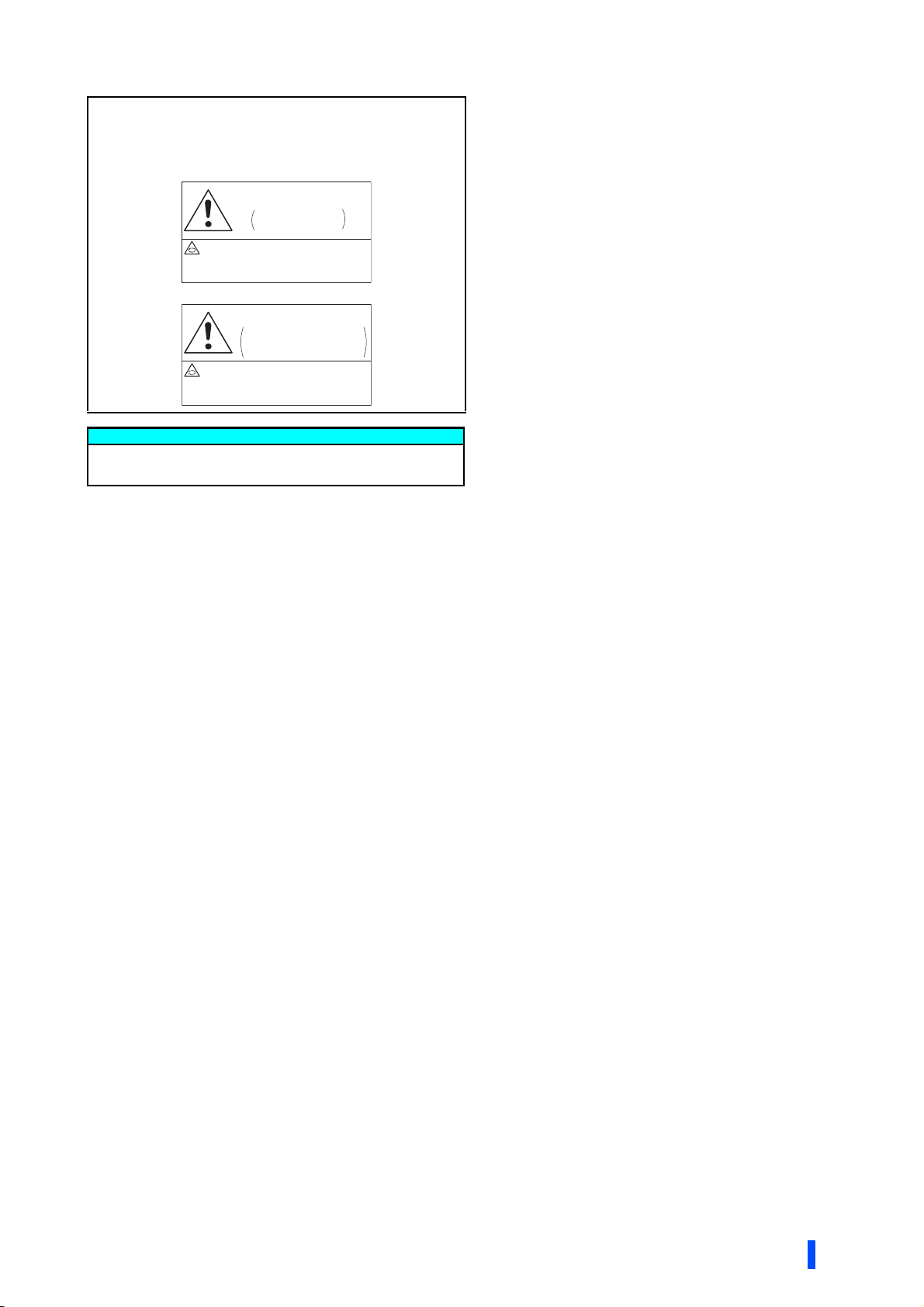
Application of caution labels
Stay away from the motor and machine.
They will start suddenly (after reset
time has elapsed) when
instantaneous power failure occurs.
CAUTION
Automatic Restart after
Instantaneous Power
Failure Has Been Selected
Caution labels are used to ensure safety during use of Mitsubishi Electric
inverters.
Apply the following labels to the inverter if the "retry function" and/or
"automatic restart after instantaneous power failure" have been enabled.
For the retry function
CAUTION
Retry Function Has
Been Selected
Stay away from the motor and machine.
They will start suddenly (after given
time has elapsed) when alarm occurs.
For automatic restart after instantaneous power failure
General instruction
For clarity, illustrations in this Instruction Manual may be drawn
with covers or safety guards removed. Ensure all covers and
safety guards are properly installed prior to starting operation.
Safety instructions
3

CONTENTS
1 INTRODUCTION 7
1.1 Product checking and accessories 8
1.2 Inverter component names 10
1.3 About the related manuals 12
2 INSTALLATION AND WIRING 13
2.1 Peripheral devices 14
2.1.1 Inverter and peripheral devices......................................................................................................................14
2.1.2 Peripheral devices .......................................................................................................................................... 16
2.2 Removal and reinstallation of the front cover 18
2.3 Installation of the inverter and enclosure design 20
2.3.1 Inverter installation environment ....................................................................................................................20
2.3.2 Cooling system types for inverter enclosure ..................................................................................................22
2.3.3 Inverter installation .........................................................................................................................................23
2.3.4 Protruding the heat sink through a panel .......................................................................................................25
2.4 Terminal connection diagrams 27
2.5 Main circuit terminals 36
2.5.1 Details on the main circuit terminals of the inverter........................................................................................ 36
2.5.2 Details on the main circuit terminals of the converter unit (FR-CC2) ............................................................. 36
2.5.3 Terminal layout of the main circuit terminals, wiring of power supply and the motor ..................................... 37
2.5.4 Applicable cables and wiring length ...............................................................................................................38
2.5.5 Earthing (grounding) precautions...................................................................................................................40
2.6 Control circuit 41
2.6.1 Details on the control circuit terminals of the inverter..................................................................................... 41
2.6.2 Details on the control circuit terminals of the converter unit (FR-CC2) .......................................................... 45
2.6.3 Control logic (sink/source) change ................................................................................................................. 46
2.6.4 Wiring of inverter control circuit ......................................................................................................................48
2.6.5 Wiring precautions..........................................................................................................................................50
2.6.6 When using separate power supplies for the control circuit and the main circuit...........................................51
2.6.7 When supplying 24 V external power to the control circuit............................................................................. 52
2.6.8 Safety stop function ........................................................................................................................................ 54
2.7 Communication connectors and terminals 56
2.7.1 PU connector.................................................................................................................................................. 56
2.7.2 USB connector ............................................................................................................................................... 57
2.7.3 RS-485 terminal block (RS-485 model).......................................................................................................... 58
2.7.4 Ethernet port (Ethernet model)....................................................................................................................... 59
2.8 Connection of motor with encoder (vector control) 60
2.9 Parameter settings for a motor with encoder 65
2.10 Connection of stand-alone option units 66
2.10.1 Connection of the brake unit (FR-BU2) .......................................................................................................... 66
2.10.2 Connection of the high power factor converter (FR-HC2) ..............................................................................67
2.10.3 Connection of the power regeneration converter (MT-RC) ............................................................................ 68
4
CONTENTS

2.11 Installing a communication option 69
3 PRECAUTIONS FOR USE OF THE INVERTER 71
3.1 Electro-magnetic interference (EMI) and leakage currents 72
3.1.1 Leakage currents and countermeasures ........................................................................................................72
3.1.2 Precautions against inverter-generated EMI ..................................................................................................75
3.1.3 Converter unit (FR-CC2) built-in EMC filter ....................................................................................................78
3.2 Power supply harmonics 79
3.2.1 Power supply harmonics.................................................................................................................................79
3.2.2 Harmonic Suppression Guidelines in Japan...................................................................................................80
3.3 Installation of a reactor 82
3.4 Power-OFF and magnetic contactor (MC) 83
3.5 Countermeasures against deterioration of the 400 V class motor insulation 84
3.6 Checklist before starting operation 85
3.7 Failsafe system which uses the inverter 88
4 PROTECTIVE FUNCTIONS 91
4.1 Inverter fault and indications 92
4.2 Reset method for the protective functions 92
4.3 Check and clear of the fault history 93
4.4 List of fault displays 95
5 PRECAUTIONS FOR
MAINTENANCE AND INSPECTION 97
5.1 Inspection item 98
5.1.1 Daily inspection...............................................................................................................................................98
5.1.2 Periodic inspection..........................................................................................................................................98
5.1.3 Daily and periodic inspection ..........................................................................................................................99
5.1.4 Checking the inverter and converter semiconductor devices .......................................................................100
5.1.5 Cleaning........................................................................................................................................................101
5.1.6 Replacement of parts....................................................................................................................................101
5.1.7 Removal and reinstallation of the control circuit terminal block ....................................................................104
5.2 Measurement of main circuit voltages, currents and powers 105
5.2.1 Measurement of powers ...............................................................................................................................107
5.2.2 Measurement of voltages .............................................................................................................................107
5.2.3 Measurement of currents ..............................................................................................................................107
5.2.4 Example of measuring converter unit (FR-CC2) input power factor.............................................................107
5.2.5 Measurement of converter output voltage (across terminals P and N).........................................................107
CONTENTS
5

5.2.6 Measurement of inverter output frequency................................................................................................... 108
5.2.7 Insulation resistance test using megger ....................................................................................................... 108
5.2.8 Pressure test ................................................................................................................................................ 108
6 SPECIFICATIONS 109
6.1 Inverter rating 110
6.2 Common specifications 111
6.3 Outline dimension drawings 113
6.3.1 Inverter outline dimension drawings............................................................................................................. 113
APPENDIX 115
Appendix 1 Comparison with FR-A840-R2R............................................................................................ 116
Appendix 2 Instructions for compliance with the EU Directives........................................................... 117
Appendix 3 Instructions for UL and cUL ................................................................................................. 120
Appendix 4 Instructions for EAC.............................................................................................................. 122
Appendix 5 Restricted Use of Hazardous Substances in Electronic and Electrical Products ........... 123
Appendix 6 Referenced Standard (Requirement of Chinese standardized law).................................. 123
6
CONTENTS

1 INTRODUCTION
This chapter contains the descriptions that must be read before
using this product.
Always read the instructions before using the equipment.
1.1 Product checking and accessories.........................................8
1.2 Inverter component names ......................................................10
1.3 About the related manuals.......................................................12
<Abbreviations>
DU...................................................Operation panel (FR-DU08)
Operation panel ..............................Operation panel and LCD operation panel
Parameter unit ................................Parameter unit (FR-PU07)
PU...................................................Operation panel and parameter unit
Inverter............................................Mitsubishi Electric inverter FR-A800 series (Separated converter type)
FR-A800-E......................................Mitsubishi Electric inverter FR-A800 series (Ethernet model)
Ethernet board ................................Ethernet communication board (FR-A8ETH)
Vector control compatible option..... FR-A8AP/FR-A8AL/FR-A8APR/FR-A8APS (plug-in option), FR-A8TP
(control terminal option)
Pr. ................................................... Parameter number (Number assigned to function)
PU operation...................................Operation using the PU (operation panel/parameter unit)
External operation...........................Operation using the control circuit signals
Combined operation .......................Combined operation using the PU (operation panel/parameter unit) and
External operation
<Trademarks>
• Ethernet is a registered trademark of Fuji Xerox Corporation in Japan.
• Other company and product names herein are the trademarks and registered trademarks of their respective
owners.
<Notes on descriptions in this Instruction Manual>
• Connection diagrams in this Instruction Manual suppose that the control logic of the input terminal is the sink
logic, unless otherwise specified. (For the control logic, refer to page 46.)
1
Harmonic Suppression Guidelines
All the models of the inverters used by specific consumers are covered by "the Harmonic Suppression
Guidelines for Consumers Who Receive High Voltage or Special High Voltage". For the details, refer to page 80.
INTRODUCTION
7
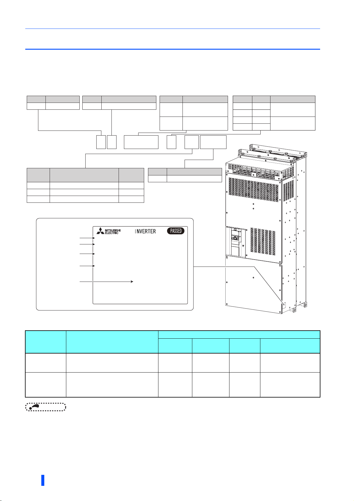
Product checking and accessories
NOTE
Rating plate
Input rating
Output rating
SERIAL
Inverter model
,1387;;;;;
02'(/)5$55
287387;;;;;
6(5,$/;;;;;;;;;
0$'(,1;;;;;
F R - A 8 4 2 -
07700
- 1 -
400 V class
Symbol Voltage class
4
Symbol
Circuit board coating
(conforming to IEC 60721-3-3 3C2/3S2)
WithoutNone
With
With
Plated
conductor
Without
With
Without
06
60
Structure, functionalitySymbol
Separated converter type
2
Symbol Function
Roll to roll dedicated model
R2R
R2R
CA
Symbol Type
∗1
FM
2
1
FM
CA
E1
E2
Communication
RS-485
Ethernet
Country of origin
Symbol Description
315K
to 500K
07700
to 12120
Inverter ND
rated capacity (kW)
Inverter SLD
rated current (A)
1.1 Product checking and accessories
Unpack the product and check the rating plate and the capacity plate of the inverter to ensure that the model agrees with the
order and the product is intact.
Applicable inverter model
∗1 Specification differs by the type as follows.
Typ e Monitor output
FM
(terminal FM
equipped model)
CA
(terminal CA
equipped model)
• Hereinafter, the inverter model name consists of the rated current and the applicable motor capacity.
(Example) FR-A842-07700(315K)
Terminal FM (pulse train output)
Terminal AM (analog voltage output (0 to
±10 VDC))
Terminal CA (analog current output (0 to
20 mA DC))
Terminal AM (analog voltage output (0 to
±10 VDC))
Built-in
EMC filter
OFF Sink logic 60 Hz
ON Source logic 50 Hz
Control logic
Initial setting
frequency
Rated
Pr.19 Base frequency
voltage
9999 (same as the power
supply voltage)
8888 (95% of the power
supply voltage)
8
INTRODUCTION

Product checking and accessories
How to read the SERIAL number
Rating plate example
Symbol Year Month Control number
SERIAL
The SERIAL consists of one symbol, two characters indicating the production
year and month, and six characters indicating the control number.
The last digit of the production year is indicated as the Year, and the Month is
indicated by 1 to 9, X (October), Y (November), or Z (December).
Accessory
• Earthing (grounding) cable (1): For connection with a communication option.(Ethernet model) (Refer to page 69.)
• CD-ROM (1): Including the Instruction Manual (Detailed) and other documents.
INTRODUCTION
1
9
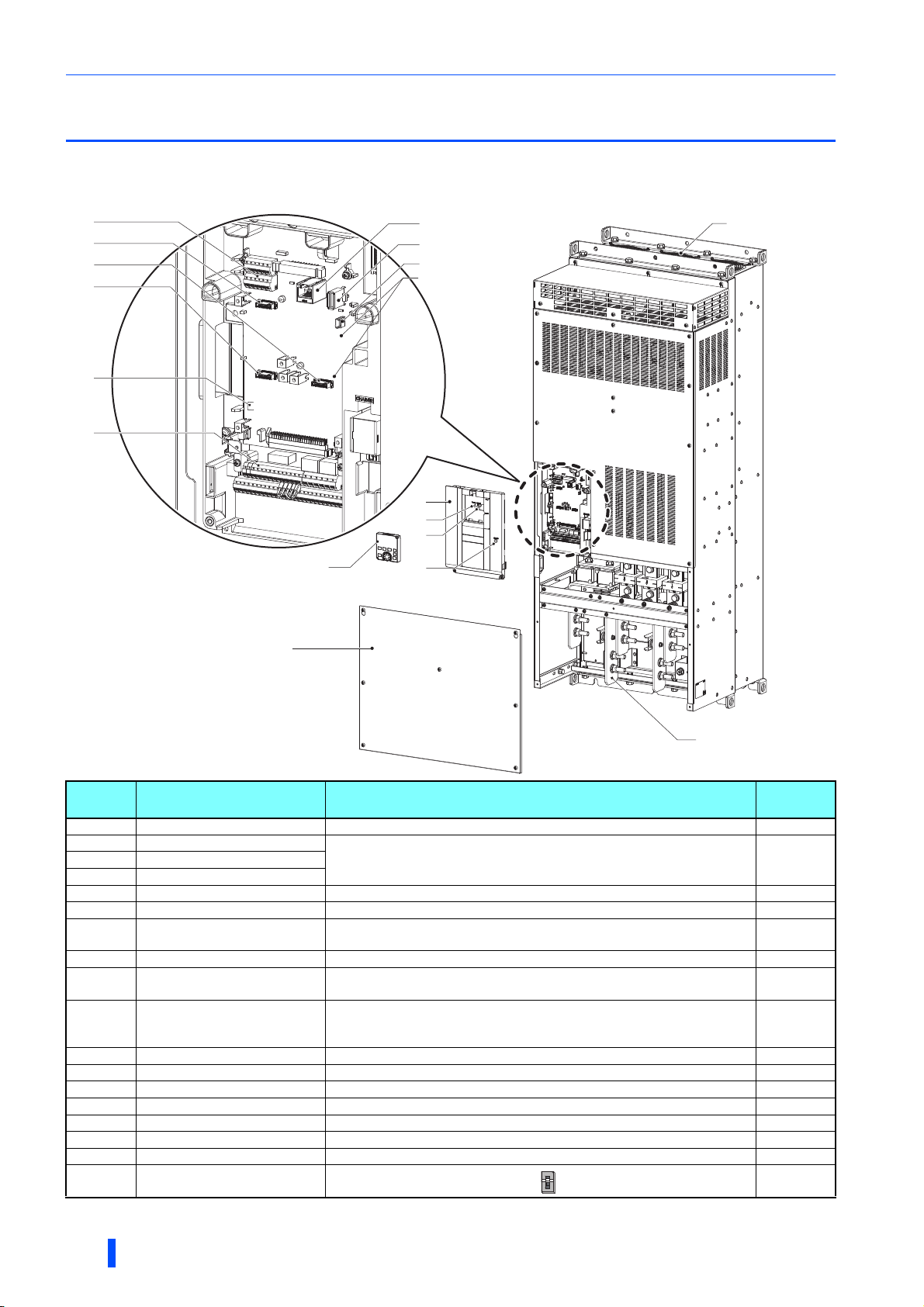
Inverter component names
OFF
ON
1.2 Inverter component names
Component names are shown below.
RS-485 model
(a)
(d)
(b)
(c)
(e)
(f)
(g)
(h)
(i)
(r)
(j)
(k)
(l)
(q)
(n)
(o)
(m)
(p)
Symbol Name Description
(a) RS-485 terminals Enables RS-485 and MODBUS RTU communication. 58
(b) Plug-in option connector 1
(c) Plug-in option connector 2
(d) Plug-in option connector 3
(e) Voltage/current input switch Selects between voltage and current for the terminal 2 and 4 inputs.
(f) Control circuit terminal block Connects cables for the control circuit. 41
(g) PU connector
(h) USB A connector Connects a USB memory device. 57
(i) USB mini B connector
(j) Front cover
(k) Power lamp Stays ON while the power is supplied to the control circuit (R1/L11, S1/L21). 37
(l) Alarm lamp Turns ON when the protective function of the inverter is activated. 91
(m) Charge lamp Stays ON while the power is supplied to the main circuit. 37
(n) Operation panel (FR-DU08) Operates and monitors the inverter.
(o) Terminal block cover Remove this cover for wiring. 18
(p) Main circuit terminal block Connects cables for the main circuit. 36
(q) Cooling fan Cools the inverter. 102
(r)
Switches for manufacturer
setting (SW3 and SW4)
∗1 Refer to the FR-A800 Instruction Manual (Detailed)
Connects a plug-in option or a communication option.
Connects the operation panel (FR-DU08) or the parameter unit (FR-PU07).
This connector also enables the RS-485 communication.
Connects a personal computer and enables communication with FR
Configurator 2.
Remove this cover for the installation of the product, installation of a plug-in
(communication) option, RS-485 terminal wiring, switching of the voltage/
current input switch, etc.
Do not change the initial setting (OFF ).
Instruction
Manual of
the option
∗1
56
57
18
∗1
─
Refer to
page
10
INTRODUCTION
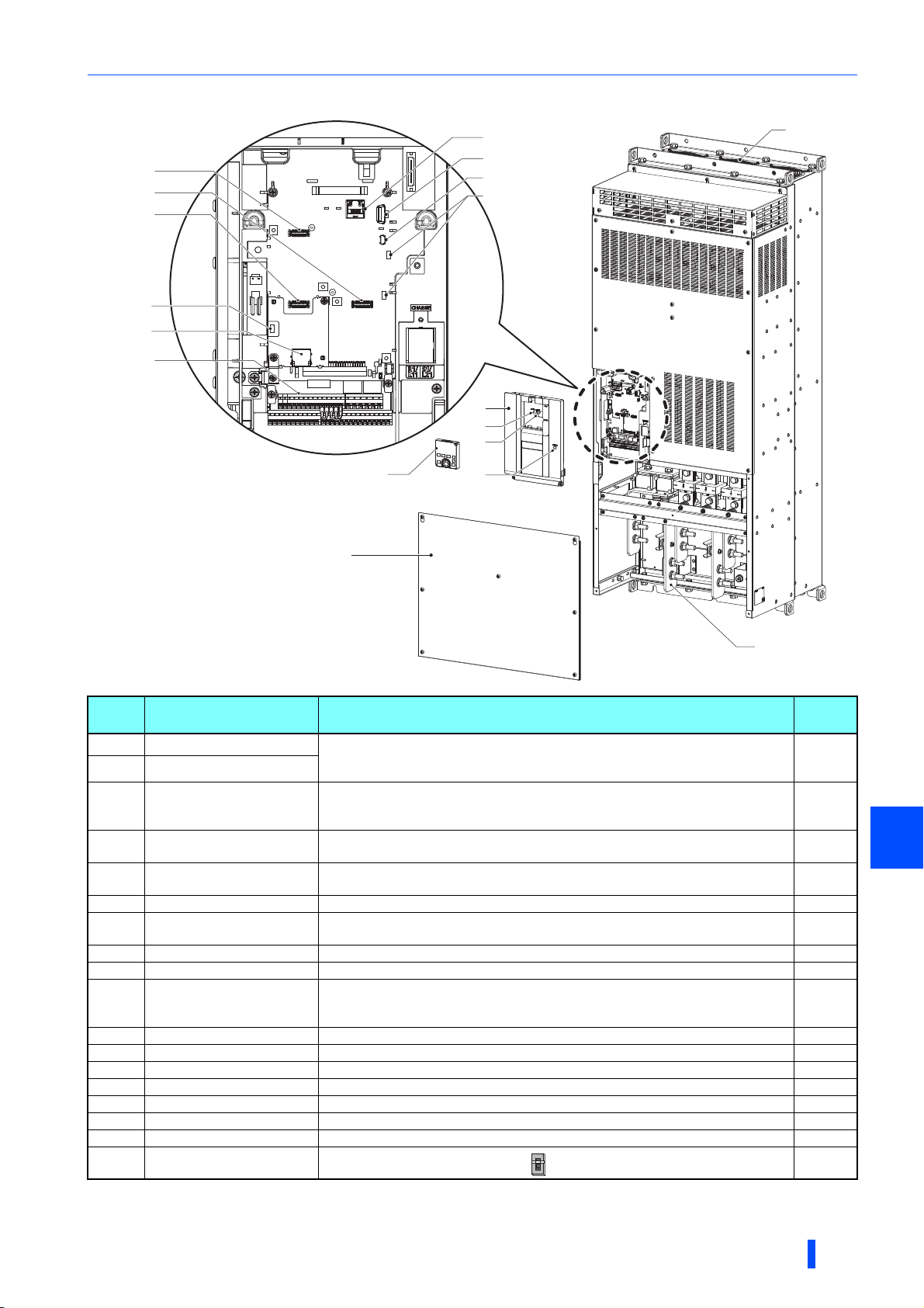
Ethernet model
(g)
(f)
(d)
(e)
(b)
(a)
(c)
(h)
(i)
(r)
(p)
(k)
(m)
(n)
(l)
(j)
(o)
(q)
OFF
ON
Inverter component names
Symbol Name Description
(a) Plug-in option connector 1
(b) Plug-in option connector 3
(c) Plug-in option connector 2
(d)
(e)
(f) Control circuit terminal block Connects cables for the control circuit. 41
(g) PU connector
(h) USB A connector Connects a USB memory device. 57
(i) USB mini B connector Connects a personal computer and enables communication with FR Configurator2. 57
(j) Upper front cover
(k) Power lamp Stays ON while the power is supplied to the control circuit (R1/L11, S1/L21). 37
(l) Alarm lamp Turns ON when the protective function of the inverter is activated. 37
(m) Charge lamp Stays ON while the power is supplied to the main circuit. 37
(n) Operation panel (FR-DU08) Operates and monitors the inverter.
(o) Lower front cover Remove this cover for wiring. 18
(p) Main circuit terminal block Connects cables for the main circuit. 36
(q) Cooling fan Cools the inverter. 102
(r)
Voltage/current input switch
(SW2)
Ethernet communication
connector
Switches for manufacturer
setting (SW3 and SW4)
∗1 Refer to the FR-A800 Instruction Manual (Detailed)
Connects a plug-in option or a communication option.
The connector 2 cannot be used because the Ethernet board is installed in the initial
status. The Ethernet board must be removed to install a plug-in option to the
connector 2. (However, Ethernet communication is disabled in that case.)
Selects between voltage and current for the terminal 2 and 4 inputs.
Connect the Ethernet dedicated cable for connection to the network. 59
Connects the operation panel or the parameter unit. This connector also enables the
RS-485 communication.
Remove this cover for the installation of the product, installation of a plug-in
(communication) option, RS-485 terminal wiring, switching of the voltage/current input
switch, etc.
Do not change the initial setting (OFF ).
Refer to
page
Instruction
Manual of
the option
59
∗1
56
18
∗1
─
1
INTRODUCTION
11

About the related manuals
1.3 About the related manuals
The manuals related to FR-A800 are shown below.
Manual name Manual number
FR-A800 Instruction Manual (Detailed) IB-0600503ENG
Roll to Roll Function Manual IB-0600622ENG
FR-A800-E-R2R Ethernet Function Manual IB-0600813ENG
FR-CC2 Instruction Manual IB-0600543ENG
FR Configurator2 Instruction Manual IB-0600516ENG
FR-A800 PLC Function Programming Manual IB-0600492ENG
FR-A800 Safety stop function instruction manual BCN-A23228-001
12
INTRODUCTION

2 INSTALLATION AND
WIRING
This chapter explains the "installation" and the "wiring" of this
product.
Always read the instructions before using the equipment.
2.1 Peripheral devices ....................................................................14
2.2 Removal and reinstallation of the front cover........................18
2.3 Installation of the inverter and enclosure design ..................20
2.4 Terminal connection diagrams ................................................27
2.5 Main circuit terminals...............................................................36
2.6 Control circuit ...........................................................................41
2.7 Communication connectors and terminals ............................56
2.8 Connection of motor with encoder (vector control) ..............60
2.9 Parameter settings for a motor with encoder ........................65
2.10 Connection of stand-alone option units .................................66
2.11 Installing a communication option..........................................69
2
INSTALLATION AND WIRING
13
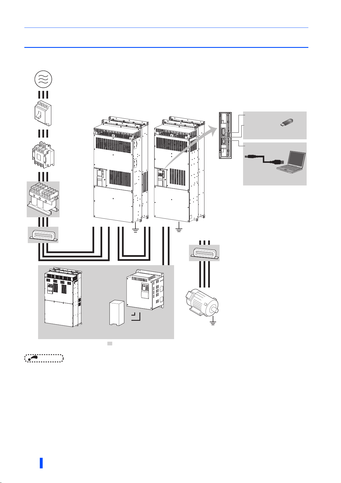
Peripheral devices
NOTE
Earth
(Ground)
R/L1 S/L2T/L3 N/-N/- P/+P/+ N/-P/+
P/+
P/+
PR
PR
: Install these options as required.
UVW
(d) Moulded case
circuit breaker
(MCCB) or earth
leakage current
breaker (ELB),
fuse
(l) Noise filter
(g) Noise filter
(h) High power factor converter
(FR-HC2)
(j) Resistor unit
(MT-BR5)
(i) Brake unit
(FR-BU2)
(e) Magnetic
contactor
(MC)
(a) Inverter
(FR-A802)
(b) Converter unit
(FR-CC2)
(c) Three-phase AC power supply
(k) USB connector
Personal computer
(FR Configurator 2)
USB
USB host
(A connector)
USB device
(Mini B connector)
Communication
status indicator
(LED)(USB host)
Earth
(Ground)
(m) Induction
motor
(f) AC reactor
(FR-HAL)
Earth
(Ground)
2.1 Peripheral devices
2.1.1 Inverter and peripheral devices
• To prevent an electric shock, always earth (ground) the motor, the inverter, and the converter unit.
• Do not install a power factor correction capacitor or surge suppressor or capacitor type filter on the inverter's output side. Doing
so will cause the inverter to trip or the capacitor and surge suppressor to be damaged. If any of the above devices is connected,
immediately remove it. When installing a molded case circuit breaker on the output side of the inverter, contact the manufacturer
of the molded case circuit breaker.
• Electromagnetic wave interference
The input/output (main circuit) of the inverter or the converter unit includes high frequency components, which may interfere
with the communication devices (such as AM radios) used near the inverter or the converter unit. In this case, activating the
EMC filter of the converter unit may minimize interference. (Refer to page 78.)
• For details of options and peripheral devices, refer to the respective Instruction Manual.
14
INSTALLATION AND WIRING

Peripheral devices
Symbol Name Overview
The life of the inverter and the converter unit is influenced by the
(a) Inverter (FR-A802)
(b) Converter unit (FR-CC2)
(c) Three-phase AC power supply
(d)
(e) Magnetic contactor (MC)
(f) AC reactor (FR-HAL)
(g) Noise filter
(h) High power factor converter (FR-HC2)
(i) Brake unit (FR-BU2)
(j) Resistor unit (MT-BR5)
(k) USB connection
(l) Noise filter
(m) Induction motor Connect a squirrel-cage induction motor. —
Molded case circuit breaker (MCCB),
earth leakage circuit breaker (ELB), or
fuse
surrounding air temperature.
The surrounding air temperature should be as low as possible within the
permissible range. This must be noted especially when the inverter is
installed in an enclosure.
Incorrect wiring may lead to damage of the inverter and the converter unit.
The control signal lines must be kept fully away from the main circuit lines
to protect them from noise.
The converter unit built-in EMC filter can reduce the noise.
Must be within the permissible power supply specifications of the converter
unit.
Must be selected carefully since an inrush current flows in the converter
unit at power ON.
Install this to ensure safety.
Do not use this to start and stop the inverter. Doing so will shorten the life of
the inverter and the converter unit.
Install this to suppress harmonics and to improve the power factor.
An AC reactor (FR-HAL) (option) is required when installing the inverter
near a large power supply system (1000 kVA or more). Under such
condition, the inverter and the converter unit may be damaged if you do not
use a reactor.
Select a reactor according to the applied motor capacity.
Suppresses the noise radiated from the power supply side of the converter
unit.
Suppresses the power supply harmonics significantly. Install these options
as required.
When FR-HC2 is used, FR-CC2 is not required.
Allows the inverter to provide the optimal regenerative braking capability.
Install these options as required.
A USB (Ver. 1.1) cable connects the inverter with a personal computer.
A USB memory device enables parameter copies and the trace function.
Install this to reduce the electromagnetic noise generated from the inverter
and the converter unit. The noise filter is effective in the range from about
0.5 MHz to 5 MHz.
Refer
to page
20
27
78
110
16
83
82
75
67
66
57
75
INSTALLATION AND WIRING
2
15
Peripheral devices
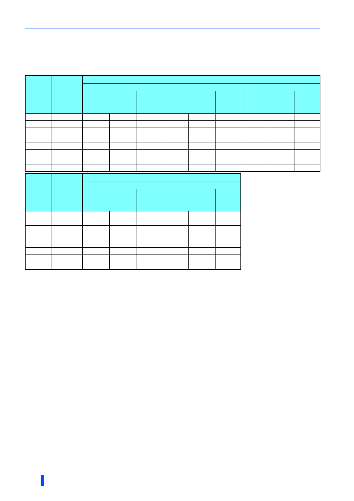
2.1.2 Peripheral devices
Selecting the converter unit (FR-CC2)
Select the capacity of the FR-CC2 converter unit according to the connected motor capacity.
Inverter
Motor
capacity
(kW)
280H315---------
315 H315K - - - - - - - - -
355 H355K - - - 315K 07700 683 315K 07700 683
400 H400K 315K 07700 770 355K 08660 770 355K 08660 770
450 H450K 355K 08660 866 400K 09620 866 400K 09620 866
500 H500K 400K 09620 962 450K 10940 962 450K 10940 962
560 H560K 450K 10940 1094 500K 12120 1094 500K 12120 1094
630 H630K 500K 12120 1212 - - - - - -
Motor
capacity
(kW)
280 H315 - - - 315K 07700 547
315 H315K 315K 07700 610 355K 08660 610
355 H355K 355K 08660 683 400K 09620 683
400 H400K 400K 09620 770 450K 10940 770
450 H450K 450K 10940 866 500K 12120 866
500 H500K 500K 12120 962 - - -
560 H560K - - - - - -
630 H630K - - - - - -
Converter
unit
FR-CC2-[ ]
∗1
Converter
unit
FR-CC2-[ ]
∗1
∗1 The applicable motor capacity indicated is the maximum capacity applicable for use of the Mitsubishi Electric 4-pole standard motor.
SLD (superlight duty) LD (light duty) SND (super normal duty)
Model
FR-A842-[ ]
ND (normal duty, initial value) HD (heavy duty)
Model
FR-A842-[ ]
Rated
current
(A)
Inverter
Rated
current
(A)
Model
FR-A842-[ ]
Model
FR-A842-[ ]
Rated
current
(A)
Rated
current
(A)
Model
FR-A842-[ ]
Rated
current
(A)
16
INSTALLATION AND WIRING
Peripheral devices
MCCB Converter unit
MCCB Converter unit
M
M
INV
INV
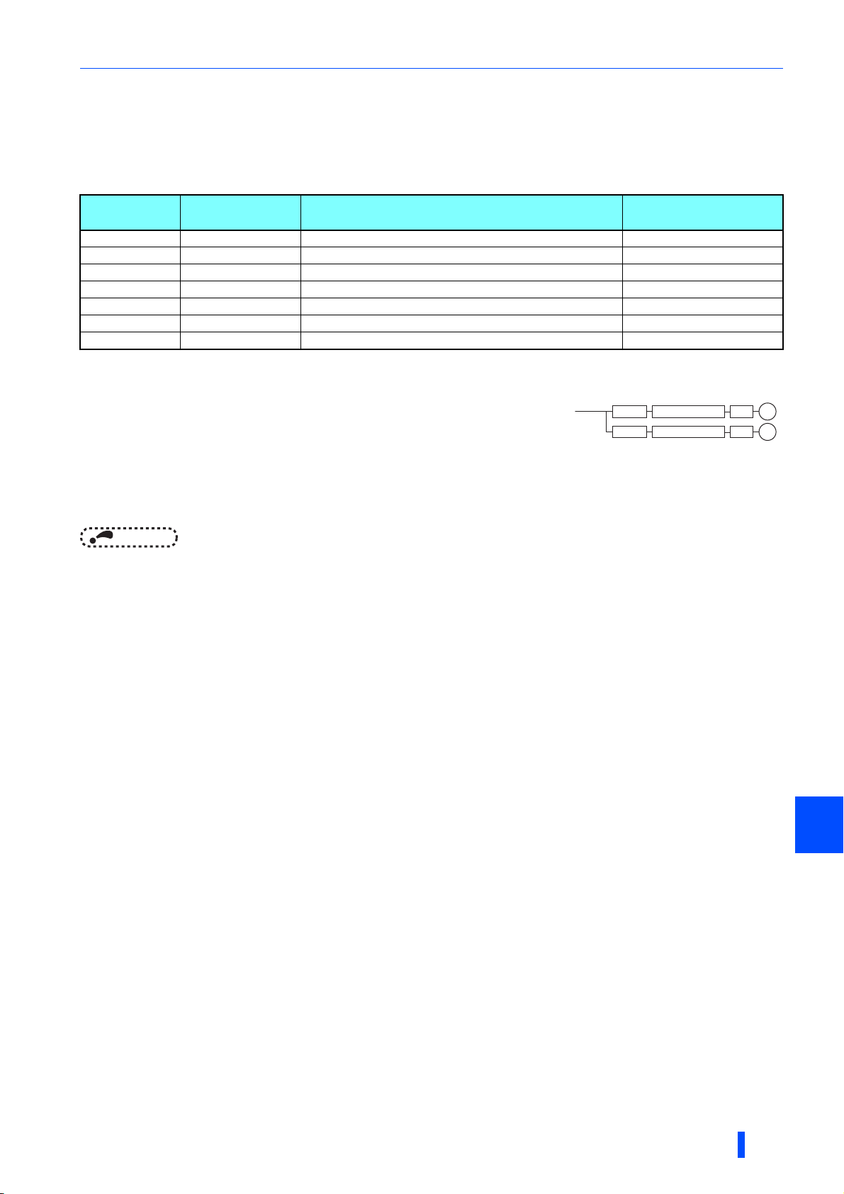
Selecting the breaker/magnetic contactor
Check the model of the inverter and the converter unit you purchased. Appropriate peripheral devices must be selected
according to the capacity.
Refer to the table below to prepare appropriate peripheral devices.
• 400 V class
Motor output
(kW)
∗1
315 FR-CC2-H315K 700 A S-N600
355 FR-CC2-H355K 800 A S-N600
400 FR-CC2-H400K 900 A S-N800
450 FR-CC2-H450K 1000 A 1000 A rated product
500 FR-CC2-H500K 1200 A 1000 A rated product
560 FR-CC2-H560K 1500 A 1200 A rated product
630 FR-CC2-H630K 2000 A 1400 A rated product
∗1 Assumes the use of a Mitsubishi Electric 4-pole standard motor with the power supply voltage
of 400 VAC 50 Hz.
∗2 Select an MCCB according to the power supply capacity.
Install one MCCB per converter.
(For the use in the United States or Canada, refer to page 120 to select an appropriate fuse.)
∗3 The magnetic contactor is selected based on the AC-1 class. The electrical durability of magnetic contactor is 500,000 times. When the
magnetic contactor is used for emergency stops during motor driving, the electrical durability is 25 times.
If using an MC for emergency stop during driving the motor, select an MC regarding the converter unit input side current as JEM 1038-AC-3
class rated current. When using an MC on the inverter output side for commercial-power supply operation switching using a general-purpose
motor, select an MC regarding the rated motor current as JEM 1038-AC-3 class rated current.
Applicable
converter model
Molded case circuit breaker (MCCB) ∗2 or
earth leakage circuit breaker (ELB) (NF, NV type)
Input-side magnetic
contactor
∗3
NOTE
• The above shows a selection example for the ND rating. For selecting the SLD rating, LD rating, SND rating, or HD rating,
refer to the Technical News (MF-X-130) contained in the enclosed CD-ROM.
• When the converter unit capacity is larger than the motor capacity, select an MCCB and a magnetic contactor according to
the converter unit model, and select cables and reactors according to the motor output.
• When the breaker on the converter unit's input side trips, check for the wiring fault (short circuit), damage to internal parts of
the inverter and the converter unit, etc. The cause of the trip must be identified and removed before turning ON the power of
the breaker.
2
INSTALLATION AND WIRING
17
Removal and reinstallation of the front cover
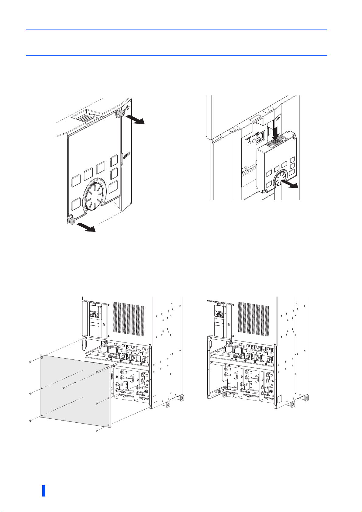
2.2 Removal and reinstallation of the front cover
Removal and reinstallation of the operation panel
• Loosen the two screws on the operation panel.
(These screws cannot be removed.)
To reinstall the operation panel, align its connector on the back with the PU connector of the inverter, and insert the operation
panel. After confirming that the operation panel is fit securely, tighten the screws. (Tightening torque: 0.40 to 0.45 N·m)
• Press the upper edge of the operation panel while pulling
out the operation panel.
Removal of the terminal block cover
(a) (b)
(a) Remove the mounting screws to remove the terminal block cover. (The number of the mounting screws differs by the capacity.)
(b) With the terminal block cover removed, the main circuit terminals can be wired.
18
INSTALLATION AND WIRING
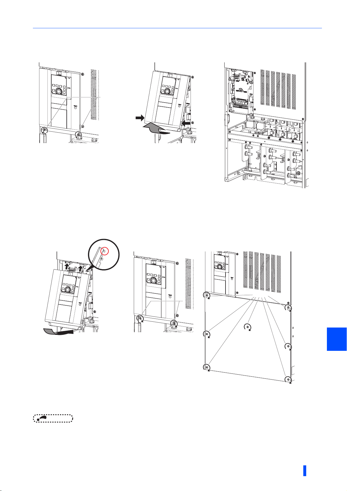
Removal of the front cover
Loosen
Tighten
Tighten
Removal and reinstallation of the front cover
(a) (b)
Loosen
Loosen
(a) With the terminal block cover removed, loosen the screws on the front cover. These screws cannot be removed.
(b) While holding the areas around the installation hooks on the sides of the front cover, pull out the front cover using its upper side
as a support.
(c) With the front cover removed, the control circuit and the RS-485 terminals can be wired, and the plug-in option can be installed.
(c)
Reinstallation of the front cover and the terminal block cover
(a)
(a) Clip on the front cover as illustrated.
Check that it is properly secured.
(b) Tighten the screws on the lower part of the front cover.
(c) Attach the terminal block cover using the screws. (The number of screws differs depending on the capacity of the inverter.)
(b) (c)
Tighten
Tighten
Tighten
Tighten
2
NOTE
• Fully make sure that the front cover and the terminal block cover are installed securely. Always tighten the mounting screws
of the front cover and the terminal block cover.
INSTALLATION AND WIRING
19
Installation of the inverter and enclosure design
Measurement
position
Measurement
position
Inverter
5 cm
5 cm
5 cm
2.3 Installation of the inverter and enclosure design
When designing or manufacturing an inverter enclosure, determine the structure, size, and device layout of the enclosure by
fully considering the conditions such as heat generation of the contained devices and the operating environment. An inverter
uses many semiconductor devices. To ensure higher reliability and long period of operation, operate the inverter in the
ambient environment that completely satisfies the equipment specifications.
2.3.1 Inverter installation environment
The following table lists the standard specifications of the inverter installation environment. Using the inverter in an
environment that does not satisfy the conditions deteriorates the performance, shortens the life, and causes a failure. Refer to
the following points, and take adequate measures.
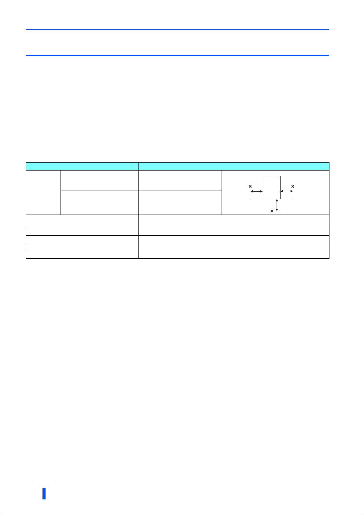
Standard environmental specifications of the inverter
Item Description
Surrounding
air
temperature
Surrounding air humidity
Storage temperature -20 to + 65°C
Atmosphere Indoors (free from corrosive gas, flammable gas, oil mist, dust and dirt)
Altitude Maximum 2500 m
Vibration
LD, SND, ND (initial setting), HD -10 to +50°C (non-freezing)
SLD -10 to +40°C (non-freezing)
With circuit board coating 95% RH or less (non-condensing)
Without circuit board coating 90% RH or less (non-condensing)
∗1
∗2
2
2.9 m/s
or less at 10 to 55 Hz (directions of X, Y, Z axes)
∗1 Temperature applicable for a short time, e.g. in transit.
∗2 For the installation at an altitude above 1000 m, derate the rated current 3% per 500 m.
Temperature
The permissible surrounding air temperature of the inverter is between -10°C and +50°C (-10°C and +40°C at the SLD rating).
Always operate the inverter within this temperature range. Operation outside this range will considerably shorten the service
lives of the semiconductors, parts, capacitors and others. Take the following measures to keep the surrounding air
temperature of the inverter within the specified range.
(a) Measures against high temperature
• Use a forced ventilation system or similar cooling system. (Refer to page 22.)
• Install the enclosure in an air-conditioned electric chamber.
• Block direct sunlight.
• Provide a shield or similar plate to avoid direct exposure to the radiated heat and wind of a heat source.
• Ventilate the area around the enclosure well.
(b) Measures against low temperature
• Provide a space heater in the enclosure.
• Do not power OFF the inverter. (Keep the start signal of the inverter OFF.)
(c) Sudden temperature changes
• Select an installation place where temperature does not change suddenly.
• Avoid installing the inverter near the air outlet of an air conditioner.
• If temperature changes are caused by opening/closing of a door, install the inverter away from the door.
20
Humidity
Operate the inverter within the ambient air humidity of usually 45 to 90% (up to 95% with circuit board coating). Too high
humidity will pose problems of reduced insulation and metal corrosion. On the other hand, too low humidity may cause a
spatial electrical breakdown. The insulation distance defined in JEM 1103 "Control Equipment Insulator" is humidity of 45 to
85%.
INSTALLATION AND WIRING

Installation of the inverter and enclosure design
(a) Measures against high humidity
• Make the enclosure enclosed, and provide it with a hygroscopic agent.
• Provide dry air into the enclosure from outside.
• Provide a space heater in the enclosure.
(b) Measures against low humidity
Air with proper humidity can be blown into the enclosure from outside. Also when installing or inspecting the unit, discharge
your body (static electricity) beforehand, and keep your body away from the parts and patterns.
(c) Measures against condensation
Condensation may occur if frequent operation stops change the in-enclosure temperature suddenly or if the outside air
temperature changes suddenly.
Condensation causes such faults as reduced insulation and corrosion.
• Take the measures against high humidity in (a).
• Do not power OFF the inverter. (Keep the start signal of the inverter OFF.)
Dust, dirt, oil mist
Dust and dirt will cause such faults as poor contacts, reduced insulation and cooling effect due to the moisture-absorbed
accumulated dust and dirt, and in-enclosure temperature rise due to a clogged filter. In an atmosphere where conductive
powder floats, dust and dirt will cause such faults as malfunction, deteriorated insulation and short circuit in a short time.
Since oil mist will cause similar conditions, it is necessary to take adequate measures.
Countermeasure
• Place the inverter in a totally enclosed enclosure.
Take measures if the in-enclosure temperature rises. (Refer to page 22.)
• Purge air.
Pump clean air from outside to make the in-enclosure air pressure higher than the outside air pressure.
Corrosive gas, salt damage
If the inverter is exposed to corrosive gas or to salt near a beach, the printed board patterns and parts will corrode or the
relays and switches will result in poor contact.
In such places, take the measures given above.
Explosive, flammable gases
As the inverter is non-explosion proof, it must be contained in an explosion-proof enclosure. In places where explosion may
be caused by explosive gas, dust or dirt, an enclosure cannot be used unless it structurally complies with the guidelines and
has passed the specified tests. This makes the enclosure itself expensive (including the test charges). The best way is to
avoid installation in such places and install the inverter in a non-hazardous place.
High altitude
Use the inverter at an altitude of within 2500 m. For use at an altitude above 1000 m, derate the rated current 3% per 500 m.
If it is used at a higher place, it is likely that thin air will reduce the cooling effect and low air pressure will deteriorate dielectric
strength.
2
Vibration, impact
The vibration resistance of the inverter is up to 2.9 m/s2 at 10 to 55 Hz frequency and 1 mm amplitude for the directions of X,
Y, Z axes. Applying vibration and impacts for a long time may loosen the structures and cause poor contacts of connectors,
even if those vibration and impacts are within the specified values.
Especially when impacts are applied repeatedly, caution must be taken because such impacts may break the installation feet.
Precautions
• Provide the enclosure with rubber vibration isolators.
• Strengthen the structure to prevent the enclosure from resonance.
• Install the enclosure away from the sources of the vibration.
INSTALLATION AND WIRING
21
Installation of the inverter and enclosure design
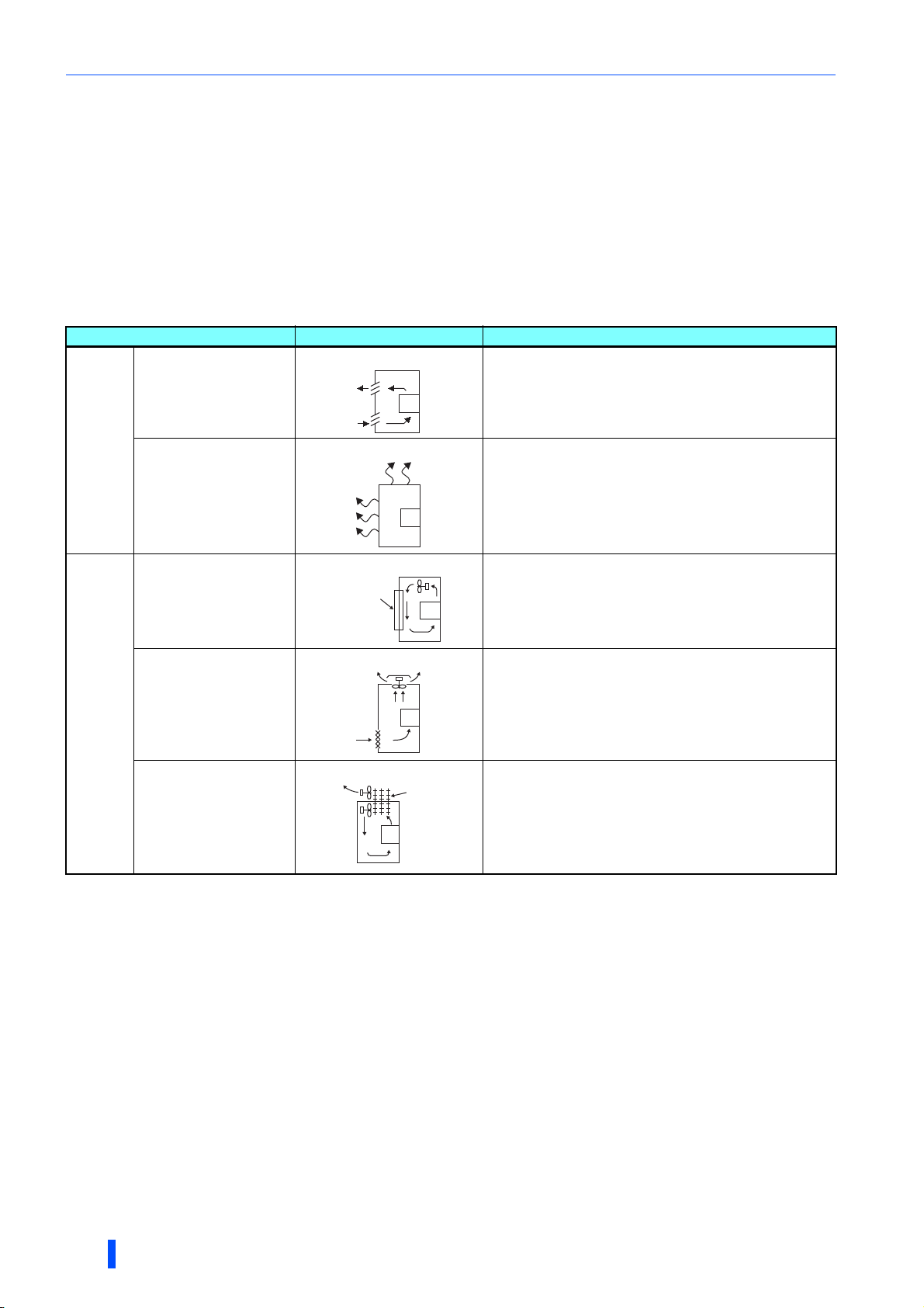
2.3.2 Cooling system types for inverter enclosure
From the enclosure that contains the inverter, the heat of the inverter and other equipment (transformers, lamps, resistors,
etc.) and the incoming heat such as direct sunlight must be dissipated to keep the in-enclosure temperature lower than the
permissible temperatures of the in-enclosure equipment including the inverter.
The cooling systems are classified as follows in terms of the cooling calculation method.
(a) Cooling by natural heat dissipation from the enclosure surface (totally enclosed type)
(b) Cooling by heat sink (aluminum fin, etc.)
(c) Cooling by ventilation (forced ventilation type, pipe ventilation type)
(d) Cooling by heat exchanger or cooler (heat pipe, cooler, etc.)
Cooling system Enclosure structure Comment
Natural
Forced air
Natural ventilation
(enclosed type / open type)
Natural ventilation (totally
enclosed type)
Heat sink cooling
Forced ventilation
Heat pipe This is a totally enclosed for enclosure downsizing.
Heat sink
INV
INV
INV
INV
Heat
pipe
INV
This system is low in cost and generally used, but the
enclosure size increases as the inverter capacity increases.
This system is for relatively small capacities.
Being a totally enclosed type, this system is the most
appropriate for hostile environment having dust, dirt, oil mist,
etc. The enclosure size increases depending on the inverter
capacity.
This system has restrictions on the heat sink mounting
position and area. This system is for relatively small
capacities.
This system is for general indoor installation. This is
appropriate for enclosure downsizing and cost reduction, and
often used.
22
INSTALLATION AND WIRING
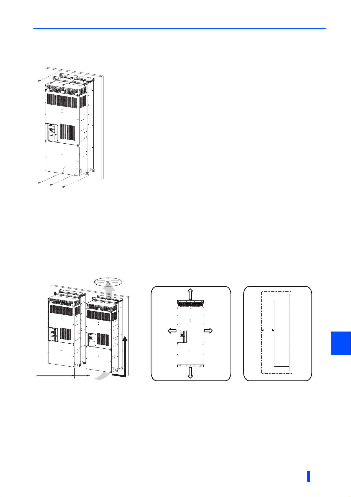
2.3.3 Inverter installation
Vertical
Inverter placement
Installation of the inverter and enclosure design
• Install the inverter on a strong surface securely with screws.
• Leave enough clearances and take cooling measures.
• Avoid places where the inverter is subjected to direct sunlight, high temperature and high humidity.
• Install the inverter on a nonflammable wall surface.
• When encasing multiple inverters in an enclosure, install them in parallel as a cooling measure.
• For heat dissipation and maintenance, keep clearance between the inverter and the other devices or enclosure surface.
The clearance below the inverter is required as a wiring space, and the clearance above the inverter is required as a heat
dissipation space.
• When designing or building an enclosure for the inverter, carefully consider influencing factors such as heat generation of
the contained devices and the operating environment.
Clearances (side)Clearances (front)
20 cm or more
5 cm
or more
∗1
Inverter
Vertical
Vertical
10 cm
or more
10 cm
or more
2
Allow clearance.
∗1 There needs to be a space of at least 30 cm in front of the inverter to replace the cooling fan. Refer to page 102 for fan replacement.
20 cm or more
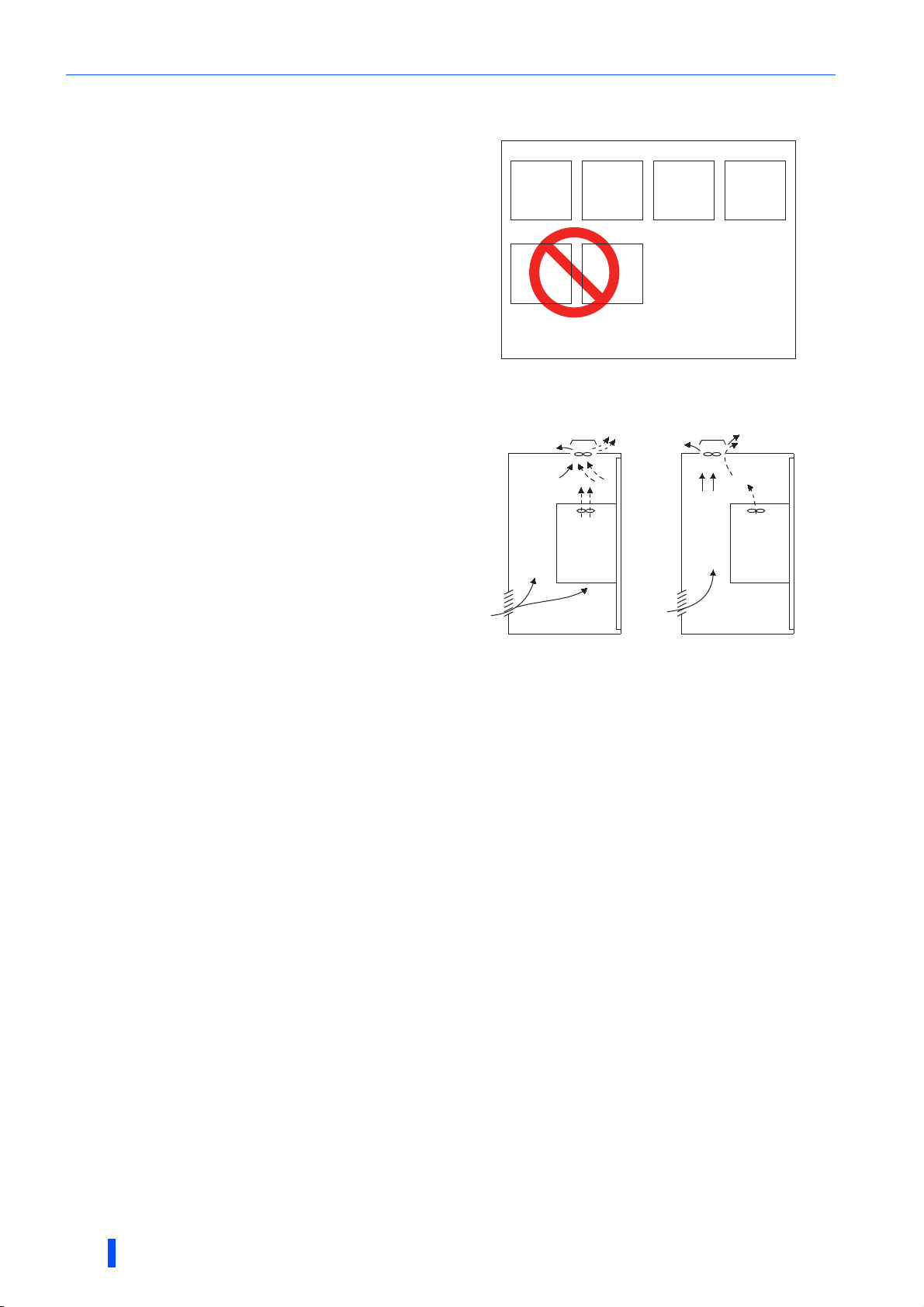
Installation orientation of the inverter
Install the inverter on a wall as specified. Do not mount it horizontally or in any other way.
Above the inverter
Heat is blown up from inside the inverter by the small fan built in the unit. Any equipment placed above the inverter should be
heat resistant.
INSTALLATION AND WIRING
23
Installation of the inverter and enclosure design
Encasing multiple inverters and converter units
When multiple inverters and converter units are placed in the
same enclosure, arrange them horizontally as shown in the
figure on the right.
Do not place multiple products vertically. The exhaust air
temperature of the inverter and the converter unit may be
increased.
When mounting multiple inverters and converter units, fully take
caution not to make the surrounding air temperature of the
inverter and the converter unit higher than the permissible value
by providing ventilation and increasing the enclosure size.
Converter
unit
Converter
unit
Arrangement of multiple inverters and converter units
Arrangement of the ventilation fan and inverter
Heat generated in the inverter is blown up from the bottom of
the unit as warm air by the cooling fan. When installing a
ventilation fan for that heat, determine the place of ventilation
fan installation after fully considering an air flow. (Air passes
through areas of low resistance. Make an airway and airflow
plates to expose the inverter to cool air.)
Inverter
Inverter
Inverter Inverter
Converter
Enclosure
unit
Inverter
<Good example> <Bad example>
Arrangement of the ventilation fan and inverter
24
INSTALLATION AND WIRING
Installation of the inverter and enclosure design
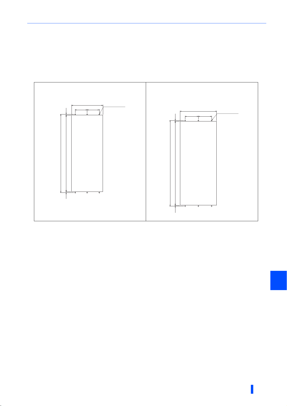
2.3.4 Protruding the heat sink through a panel
When encasing an inverter to an enclosure, the heat generated in the enclosure can be greatly reduced by protruding the
heat sink of the inverter.
When installing the inverter in a compact enclosure, etc., this installation method is recommended.
Panel cutting
Cut the panel of the enclosure according to the inverter capacity.
FR-A842-07700(315K)
FR-A842-08660(355K)
1515 1270
1300
200
520
Hole
200
6-M10 screw
(Unit: mm)
FR-A842-09620(400K)
FR-A842-10940(450K)
FR-A842-12120(500K)
15152015
1550
660
240 240
Hole
6-M10 screw
(Unit: mm)
INSTALLATION AND WIRING
2
25
Installation of the inverter and enclosure design
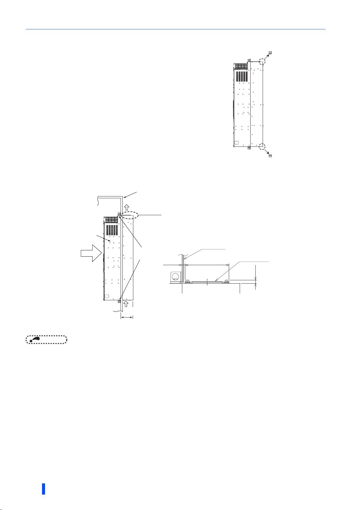
NOTE
185 mm
Exhausted air
There are finger guards behind the enclosure.
Therefore, the thickness of the panel should be
less than 10 mm (∗1) and also do not place
anything around finger guards to avoid contact
with the finger guards.
140 mm
6 mm
Inverter
Inside the
enclosure
Enclosure
Installation
frame
Dimension of
the outside of
the enclosure
Cooling
wind
Enclosure
Finger guard
10 mm
∗1
Removal of the rear installation frame
Two installation frames are attached to each of the upper and lower
parts of the inverter. Remove the rear side installation frame on the top
and bottom of the inverter as shown on the right.
Upper installation
frame (rear side)
Lower installation
frame (rear side)
Installation of the inverter
Push the inverter heat sink portion outside the enclosure and fix the enclosure and inverter with upper and lower
installation frame.
26
• Having a cooling fan, the cooling section which comes out of the enclosure cannot be used in the environment of water drops,
oil, mist, dust, etc.
• Be careful not to drop screws, dust etc. into the inverter and cooling fan section.
INSTALLATION AND WIRING
R1/L11
S1/L21
PC
Frequency setting signals (Analog)
10E(+10V)
10(+5V)
2
(Analog common)
2
3
1
Auxiliary
input
Terminal 4 input
(Current input)
1
4
Frequency setting
potentiometer
1/2W1kΩ
Running
Up to frequency
Overload
Frequency detection
Open collector output common
Sink/source common
F/C
(FM)
SD
Motor
Relay output 1
(Fault output)
C1
B1
A1
U
V
W
Indicator
(Frequency
meter, etc.)
+-
(-)
(+)
Analog signal output
(0 to ±10VDC)
Earth
(Ground)
AM
5
0 to ±5VDC selectable
0 to ±10VDC
Open collector output ∗8
Moving-coil type
1mA full-scale
Calibration
resistor
∗11
Main circuit terminal
Control circuit terminal
0 to 5VDC
0 to 10VDC
C2
B2
A2
Relay output 2
Relay output ∗7
M
0 to 20mADC
0 to 5VDC
0 to 10VDC
selectable
4 to 20mADC
TXD+
TXD-
RXD+
RXD-
GND
(SG)
Data
transmission
GND
RS-485 terminals
SINK
SOURCE
∗3
∗5
∗5
∗10
∗5
∗5
Connector for plug-in option connection
STF
STR
STP(STOP)
RH
RM
RL
JOG
RT
MRS
X10
RES
AU
CS
SD
RUN
SU
IPF
OL
FU
SE
Data
reception
(+)
(-)
5
VCC
(+)
(-)
5V
Sink logic
∗6
Earth (Ground)
N/-
P/+
Initial value
ON
OFF
42
Safety stop signal
Safety monitor output
Safety monitor output common
So (SO)
SOC
Safety stop input (Channel 1)
Shorting
wire
Safety stop input common
Safety stop input (Channel 2)
S1
S2
PC
SD
SIC
+24
SD
Brake unit
(Option)
Jumper
∗1
(Permissible load
current 100mA)
connector 1 connector 2
connector 3
24V external power
supply input
Common terminal
24VDC power supply
(Common for external power supply transistor)
Forward rotation start
Reverse rotation start
Start self-holding selection
Middle speed
High speed
Low speed
Jog operation
Second function selection
Reset
Terminal 4 input selection
Selection of automatic restart
after instantaneous power failure
Control input signals
(No voltage input allowed) ∗2
Multi-speed
selection
Contact input common
Main circuit
Control circuit
PU
connector
USB A
connector
USB
mini B
connector
Voltage/current
input switch
selectable
Terminating
resistor
Initial value
Initial value
Output stop
RDA
RDI
Converter
unit
RSO
SE
N/-
P/+
IPF
RDB
FAN
R/L1
S/L2
T/L3
OH
RES
SD
PC
+24
C1
B1
A1
∗4
∗9
24V
24V
Output shutoff
circuit
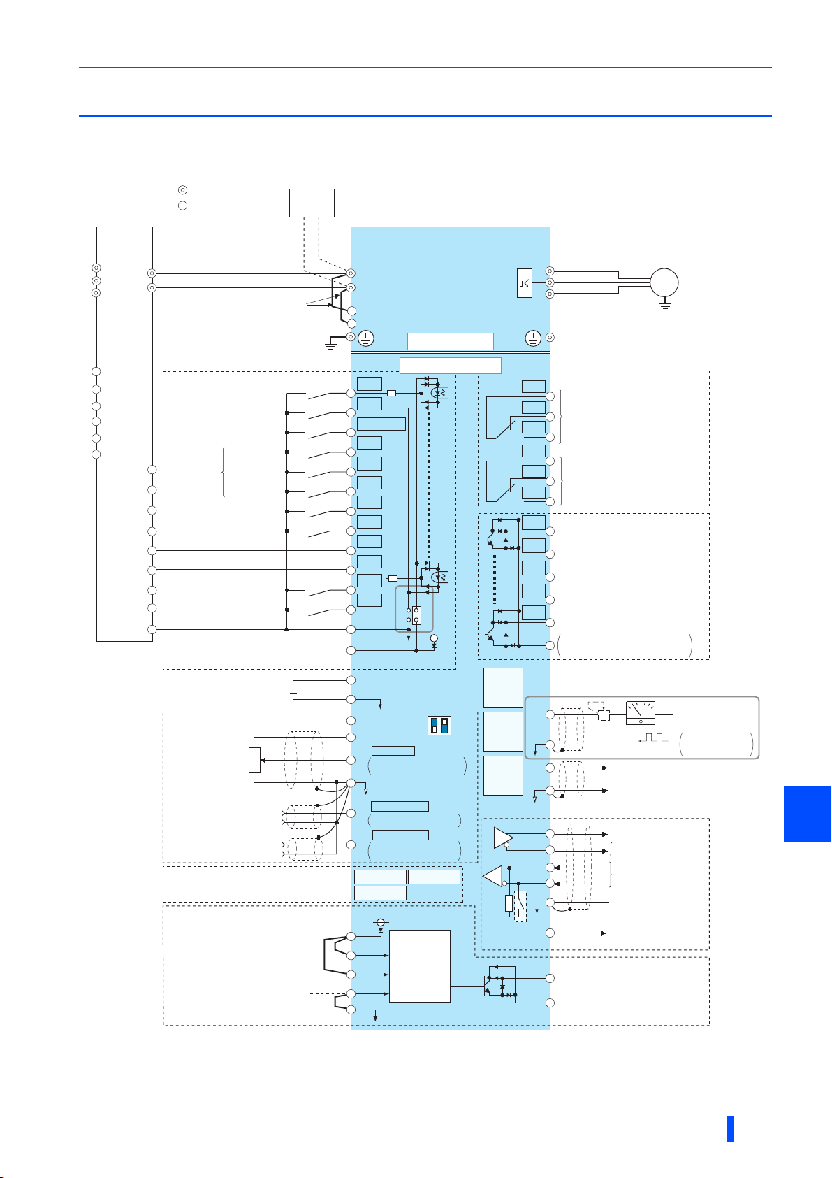
Terminal connection diagrams
2.4 Terminal connection diagrams
FM type (RS-485 model)
INSTALLATION AND WIRING
2
27

Terminal connection diagrams
NOTE
∗1 Terminals R1/L11 and S1/L21 are connected to terminals P/+ and N/- with a jumper respectively. When using separate power supply for the
control circuit, remove the jumpers from R1/L11 and S1/L21.
∗2 The function of these terminals can be changed with the input terminal assignment (Pr.178 to Pr.189).
∗3 Terminal JOG is also used as the pulse train input terminal. Use Pr.291 to choose JOG or pulse.
∗4 The X10 signal (NC contact input specification) is assigned to the terminal MRS in the initial setting. Set Pr.599 = "0" to change the input
specification of the X10 signal to NO contact.
∗5 Terminal input specifications can be changed by analog input specification switchover (Pr.73, Pr.267). To input a voltage (0 to 5 V/0 to 10 V), set
the voltage/current input switch OFF. To input a current (4 to 20 mA), set the voltage/current input switch ON. Terminals 10 and 2 are also used
as a PTC input terminal. (Pr.561)
∗6 It is recommended to use 2 W 1 kΩ when the frequency setting signal is changed frequently.
∗7 The function of these terminals can be changed with the output terminal assignment (Pr.195, Pr.196).
∗8 The function of these terminals can be changed with the output terminal assignment (Pr.190 to Pr.194).
∗9 No function is assigned in the initial setting. Use Pr.192 for function assignment.
∗10 The terminal FM can be used to output pulse trains as open collector output by setting Pr.291.
∗11 Not required when calibrating the scale with the operation panel.
• To prevent a malfunction due to noise, keep the signal cables 10 cm or more away from the power cables. Also, separate the
main circuit cables at the input side from the main circuit cables at the output side.
• After wiring, wire offcuts must not be left in the inverter.
Wire offcuts can cause an alarm, failure or malfunction. Always keep the inverter clean.
When drilling mounting holes in an enclosure etc., take caution not to allow chips and other foreign matter to enter the
inverter.
• Set the voltage/current input switch correctly. Incorrect setting may cause a fault, failure or malfunction.
28
INSTALLATION AND WIRING
R1/L11
S1/L21
PC
Frequency setting signals (Analog)
10E(+10V)
10(+5V)
2
(Analog common)
2
3
1
Auxiliary
input
Terminal 4 input
(Current input)
1
4
Frequency setting
potentiometer
1/2W1kΩ
Running
Up to frequency
Overload
Frequency detection
Open collector output common
Sink/source common
Motor
Relay output 1
(Fault output)
C1
B1
A1
U
V
W
Earth
(Ground)
0 to ±5VDC selectable
0 to ±10VDC
Open collector output ∗8
Main circuit terminal
Control circuit terminal
0 to 5VDC
0 to 10VDC
C2
B2
A2
Relay output 2
Relay output ∗7
M
0 to 20mADC
0 to 5VDC
0 to 10VDC
selectable
4 to 20mADC
TXD+
TXD-
RXD+
RXD-
GND
(SG)
Data
transmission
GND
RS-485 terminals
SINK
SOURCE
∗3
∗5
∗5
∗5
∗5
Connector for plug-in option connection
STF
STR
STP(STOP)
RH
RM
RL
JOG
RT
MRS
X10
RES
AU
CS
SD
RUN
SU
IPF
OL
FU
SE
Data
reception
(+)
(-)
5
VCC
(+)
(-)
5V
Source logic
∗6
Earth (Ground)
N/-
P/+
Initial value
ON
OFF
42
Safety stop signal
Safety monitor output
Safety monitor output common
So (SO)
SOC
Safety stop input (Channel 1)
Shorting
wire
Safety stop input common
Safety stop input (Channel 2)
S1
S2
PC
SD
SIC
+24
SD
Brake unit
(Option)
Jumper
∗1
(Permissible load
current 100mA)
connector 1 connector 2
connector 3
24V external power
supply input
Common terminal
24VDC power supply
Forward rotation start
Reverse rotation start
Start self-holding selection
Middle speed
High speed
Low speed
Jog operation
Second function selection
Reset
Terminal 4 input selection
Selection of automatic restart
after instantaneous power failure
Control input signals
(No voltage input allowed) ∗2
Multi-speed
selection
Contact input common
Main circuit
Control circuit
PU
connector
USB A
connector
USB
mini B
connector
Voltage/current
input switch
selectable
Terminating
resistor
Initial value
Initial value
Output stop
24V
24V
Output shutoff
circuit
Common for external
power supply transistor
(-)
(+)
Analog signal output
(0 to ±10VDC)
(-)
(+)
Analog current output
(0 to 20mADC)
AM
5
F/C
(CA)
RDA
RDI
Converter
unit
RSO
SE
N/-
P/+
IPF
RDB
FAN
R/L1
S/L2
T/L3
OH
RES
SD
PC
+24
C1
B1
A1
∗4
∗9
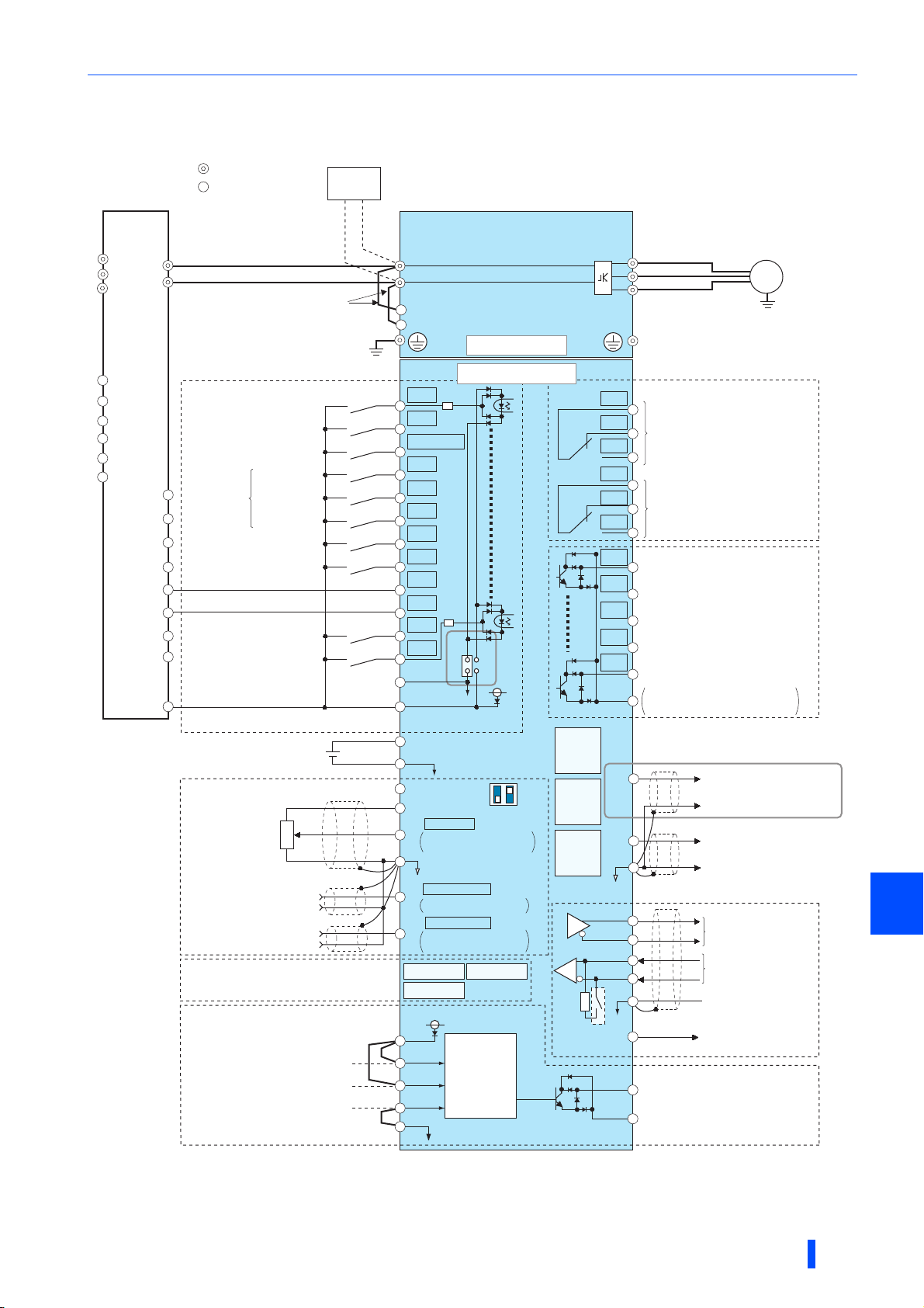
CA type (RS-485 model)
INSTALLATION AND WIRING
Terminal connection diagrams
2
29
 Loading...