

Mitsubishi Electronics Diamond Pro 2060U User Manual
AUTO-SCANNING WITH DIGITAL CONTROL
COLOR DISPLAY MONITOR
USER’S GUIDE
For future reference, record the serial
number of your display monitor in the
space below:
SERIAL No.
The serial number is located on the
rear cover of the monitor.
Internet Home Page: http://www.necmitsubishi.com/
Supplying Windows
product information, etc.
®
95/98/2000 INF File download service, new
RADIO INTERFERENCE REGULATIONS STATEMENT FOR U.S.A.
This equipment has been tested and found to comply
with the limits for a Class B digital device, pursuant to
Part 15 of the FCC Rules. These limits are designed to
provide reasonable protection against harmful interference in a residential installation. This equipment generates, uses and can radiate radio frequency energy and,
if not installed and used in accordance with the instructions, may cause harmful interference to radio communications. However, there is no guarantee that interference will not occur in a particular installation. If this
equipment does cause harmful interference to radio or
television reception, which can be determined by turning the equipment off and on, the user is encouraged to
try to correct the interference by one or more of the
following measures:
- Reorient or relocate the receiving antenna.
- Increase the separation between the equipment and
receiver.
- Connect the equipment into an outlet on a circuit
different from that to which the receiver is connected.
- Consult the dealer or an experienced radio/TV technician for help.
As an ENERGY STAR Partner, NEC-Mitsubishi
Electronics Display of America,Inc. has determined
that this product meets the ENERGY STAR guidelines for energy efficiency.
高調波ガイドライン適合品
この装置は、情報処理装置等電波障害自主規制協議会
(VCCI)の基準に基づくクラスB情報技術装置です。この装置
は、家庭環境で使用することを目的としていますが、この装
置がラジオやテレビジョン受信機に近接して使用されると、
受信障害を引き起こすことがあります。
取扱説明書に従って正しい取り扱いをしてください。
Energy 2000 Labeling Award
THIS PRODUCT HAS BEEN TESTED AND FOUND
TO COMPLY WITH THE LIMITS WITH SIGNAL
CABLE SC-B110. USE IT TO REDUCE THE POSSIBILITY OF CAUSING INTERFERENCE TO RADIO,
TELEVISION, AND OTHER ELECTRIC DEVICES.
NO USER SERVICEABLE PARTS INSIDE. DO
NOT ATTEMPT TO MODIFY THIS EQUIPMENT. IF
MODIFIED, YOUR AUTHORITY TO OPERATE THIS
EQUIPMENT MIGHT BE VOIDED BY FCC.
Declaration of Conformity - United States only
Product Name:
22 in. Color Display Monitor
Type: NSZ2107STTUW
Brand Name: MITSUBISHI
This device complies with Part 15 of the FCC Rules.
Operation is subject to the following two conditions: (1)
this device may not cause harmful interference, and (2)
this device must accept any interference received, including interference that may cause undesired operation.
For questions regarding this declaration, contact:
NEC-Mitsubishi Electronics Display of
America, Inc.
1250 North Arlington Heights Road, Itasca,
Illinois 60143-1248, U.S.A.
or, call
(630) 467-5000
To identify this product, refer to the model number found
on the product.
- ii -

Congratulations!
You have just purchased a TCO’99 approved and labelled
product! Your choice has provided you with a product
developed for professional use. Your purchase has also
contributed to reducing the burden on the environment and
also to the further development of environmentally adapted
electronics products.
Why do we have environmentally labelled computers?
In many countries, environmental labelling has become an
established method for encouraging the adaptation of
goods and services to the environment. The main problem,
as far as computers and other electronics equipment are
concerned, is that environmentally harmful substances are
used both in the products and during their manufacture.
Since it is not so far possible to satisfactorily recycle the
majority of electronics equipment, most of these potentially
damaging substances sooner or later enter nature.
There are also other characteristics of a computer, such as
energy consumption levels, that are important from the
viewpoints of both the work (internal) and natural (external)
environments. Since all methods of electricity generation
have a negative effect on the environment (e.g. acidic and
climate-influencing emissions, radioactive waste), it is vital
to save energy. Electronics equipment in offices is often left
running continuously and thereby consumes a lot of energy.
What does labelling involve?
This product meets the requirements for the TCO’99 scheme
which provides for international and environmental labelling
of personal computers. The labelling scheme was developed
as a joint effort by the TCO (The Swedish Confederation of
Professional Employees), Svenska Naturskyddsforeningen
(The Swedish Society for Nature Conservation) and Statens
Energimyndighet (The Swedish National Energy
Administration).
Approval requirements cover a wide range of issues:
environment, ergonomics, usability, emission of electric
and magnetic fields, energy consumption and electrical
and fire safety.
The environmental demands impose restrictions on the
presence and use of heavy metals, brominated and
chlorinated flame retardants, CFCs (freons) and chlorinated
solvents, among other things. The product must be prepared
for recycling and the manufacturer is obliged to have an
environmental policy which must be adhered to in each
country where the company implements its operational
policy.
The energy requirements include a demand that the
computer and/or display, after a certain period of inactivity,
shall reduce its power consumption to a lower level in one
or more stages. The length of time to reactivate the computer
shall be reasonable for the user.
Labelled products must meet strict environmental demands,
for example, in respect of the reduction of electric and
magnetic fields, physical and visual ergonomics and good
usability.
Below you will find a brief summary of the environmental
requirements met by this product. The complete
environmental criteria document may be ordered from:
TCO Development
SE-114 94 Stockholm, Sweden
Fax: +46 8 782 92 07
Email (Internet): development@tco.se
Current information regarding TCO’99 approved and
labelled products may also be
obtained via the Internet, using the address:
http://www.tco-info.com/
Environmental requirements
Flame retardants
Flame retardants are present in printed circuit boards,
cables, wires, casings and housings. Their purpose is to
prevent, or at least to delay the spread of fire. Up to 30% of
the plastic in a computer casing can consist of flame
retardant substances. Most flame retardants contain
bromine or chloride, and those flame retardants are
chemically related to another group of environmental toxins,
PCBs. Both the flame retardants containing bromine or
chloride and the PCBs are suspected of giving rise to
severe health effects, including reproductive damage in
fish-eating birds and mammals, due to the bio-accumulative
processes. Flame retardants have been found in human
blood and researchers fear that disturbances in foetus
development may occur.
The relevant TCO’99 demand requires that plastic
components weighing more than 25 grams must not contain
flame retardants with organically bound bromine or chlorine.
Flame retardants are allowed in the printed circuit boards
since no substitutes are available.
Cadmium
**
Cadmium is present in rechargeable batteries and in the
colour-generating layers of certain computer displays.
Cadmium damages the nervous system and is toxic in high
doses. The relevant TCO’99 requirement states that
batteries, the colour-generating layers of display screens
and the electrical or electronics components must not
contain any cadmium.
Mercury
**
Mercury is sometimes found in batteries, relays and
switches. It damages the nervous system and is toxic in
high doses. The relevant TCO’99 requirement states that
batteries may not contain any mercury. It also demands
that mercury is not present in any of the electrical or
electronics components associated with the labelled unit.
CFCs (freons)
The relevant TCO’99 requirement states that neither CFCs
nor HCFCs may be used during the manufacture and
assembly of the product. CFCs (freons) are sometimes
used for washing printed circuit boards. CFCs break down
ozone and thereby damage the ozone layer in the
stratosphere, causing increased reception on earth of
ultraviolet light with e.g. increased risks of skin cancer
(malignant melanoma) as a consequence.
**
Lead
Lead can be found in picture tubes, display screens,
solders and capacitors. Lead damages the nervous system
and in higher doses, causes lead poisoning. The relevant
TCO´99 requirement permits the inclusion of lead since no
replacement has yet been developed.
*
Bio-accumulative is defined as substances which
accumulate within living organisms
**
Lead, Cadmium and Mercury are heavy metals which
are Bio-accumulative.
*
- iii -

CAUTION
The power cord provided with this monitor is designed for safety and must be used with a properly
grounded outlet to avoid possible electrical shock.
Do not remove the monitor cabinet as this can
expose you to very high voltages and other hazards.
MANUFACTURER DECLARATION FOR CE-MARKING:
We, NEC-Mitsubishi Electronics Display-Europe
GmbH., declare under our sole responsibility, that this
product is in conformity with the following standards:
EN60950
EN55022 Class B
EN61000-3-2
EN61000-3-3
EN55024
following the provisions of:
73/23/EEC Low Voltage Directive
89/336/EEC EMC Directive
CONTENTS
ENGLISH
1. INTRODUCTION ..................................................... 1-2
1.1 Features........................................................ 1-2
1.2 Internal Preset Memory Capability................ 1-3
1.3 Power Management Function ....................... 1-3
1.4 DDC .............................................................. 1-3
1.5 Location Considerations ............................... 1-3
1.6 Cleaning Your Monitor .................................. 1-3
1.7 Unpacking ..................................................... 1-4
1.8 Tilt/Swivel Base............................................. 1-4
Screen Position Adjustment .......................... 1-4
1.9 Quick Operation Chart .................................. 1-4
2. PART NAME............................................................ 1-5
2.1 Control Names .............................................. 1-5
2.2 Function ........................................................ 1-5
3. INSTALLATION AND CONNECTION ..................... 1-6
3.1 AC Power Connection................................... 1-6
3.2 Signal Cable Connection .............................. 1-6
3.2.1 Connecting to any IBM VGA Compatible
System ................................................... 1-6
3.2.2 Connecting to an Apple Macintosh
Computer ............................................... 1-6
3.2.3 Connecting to two computers ................ 1-7
3.3 USB System Basic Application ..................... 1-7
3.4 Installation of USB Function ......................... 1-8
WARNING!
This product is not designed for use in life support
devices and NEC-Mitsubishi Electronics Display-Europe GmbH makes no representations to the contrary.
Life support devices are those devices which are used
to measure, diagnose, or evaluate the tissue, systems
or functions of the human body; or other devices
employed to support or sustain life or good health.
Trademark
IBM, PC, PS/2, PS/V, Personal System/2 are registered trademarks of International Business Machines Corp.
Apple Macintosh is a registered trademark of Apple Computer, Inc.
Quadra is a trademark of Apple Computer, Inc.
UNIX is a registered trademark in the United States and other
countries, licensed exclusively through X/Open Company Limited.
E
NERGY STAR
© 2000 NEC-Mitsubishi Electronics Display-Europe GmbH
is a U.S. registered mark.
4. OSD(On Screen Display) FUNCTIONS .................. 1-9
4.1 How to adjust the screen .............................. 1-9
4.2 Adjustment Items .......................................... 1-10
5. TROUBLESHOOTING ............................................ 1-12
6. SPECIFICATIONS................................................... 1-14
7. APPENDIX .............................................................. 1-15
7.1 Monitor Signal Input Connector (DB9-15P) .. 1-15
7.2 SC-B110 Signal Cable .................................. 1-15
Optional Macintosh Adapter AD-A205 Settings
7.3
1-15
- 1-1 -

1
INTRODUCTION
1
Congratulations on your purchase of the high resolution
color monitor. We designed this monitor to provide you with
years of reliable trouble-free operation.
This guide tells you how to connect, adjust and care for your
monitor. This guide also provides technical specifications
and instructions for troubleshooting any basic problems
you may experience with your monitor.
1.1 Features
This monitor is a 55cm/22" (508mm/20" Viewable Image
Size) intelligent, microprocessor-based monitor compatible with most analog RGB (Red, Green, Blue) display
standards.
It provides crisp text and vivid color graphics with both PC
and Macintosh platforms.
• The monitor’s wide auto-scanning compatibility range
makes it possible to upgrade video cards or software
without purchasing a new monitor.
• Digitally controlled auto-scanning is done using an internal microprocessor, for horizontal scan frequencies
between 30kHz and 121kHz, and vertical scan frequencies between 50Hz and 160Hz. The microprocessorbased intelligence allows the monitor to operate in each
frequency mode with the precision of a fixed frequency
monitor.
• The world's standard DIAMONDTRON NF CRT upgraded and pure picture images.
• The monitor complies with Video Electronics Standards
Association (VESA
cation. If your computer is Plug & Play compliant setup
will be done automatically.
• Fine 0.24mm aparture grille pitch/Maximum addressable resolution of 2048 x 1536.
• USB self-powered hub with 1 upstream port and 3downstream ports.
TM
) DDCTM2B and 2Bi (EDID) specifi-
• The monitor contains resident memory for pre-programmed screen display standards and is also capable
of storing additional user adjustment parameters.
• The monitor has "AUTO SIZE ADJUST" function to
optimize the size and distortion for Non-Preset timings.
• The monitor is capable of producing a non-interlaced
maximum addressable resolution format of 2048 dots x
1536 lines. This display is well suited for windowing
environments.
• Because of the analog signal inputs, the monitor can
display an unlimited palette of colors that can be manually adjusted to suit your specific needs.
• The monitor has a power management function accorded to VESA
the monitor must be connected to a system compliant
with the VESATM -DPMSTM-standard. (Refer to your
computer and/or video card instructions for proper operation.)
• To ensure ease of installation and ongoing use, the
monitor features On Screen Display (OSD) of all monitor
set-up and adjustment functions.
• For use in a variety of applications, the monitor complies
with UL 1950, CSA C22.2 No.950 and EN60950 for
safety, FCC Class-B, VCCI Class-B and EN55022 ClassB for EMI, MPR-II, ISO 9241-3, ISO9241-7 and ISO92418 for ergonomics. The monitor also complies with TCO’99
guideline for environmental safe use.
TM
-DPMSTM-standard. To save energy,
-1-2 -
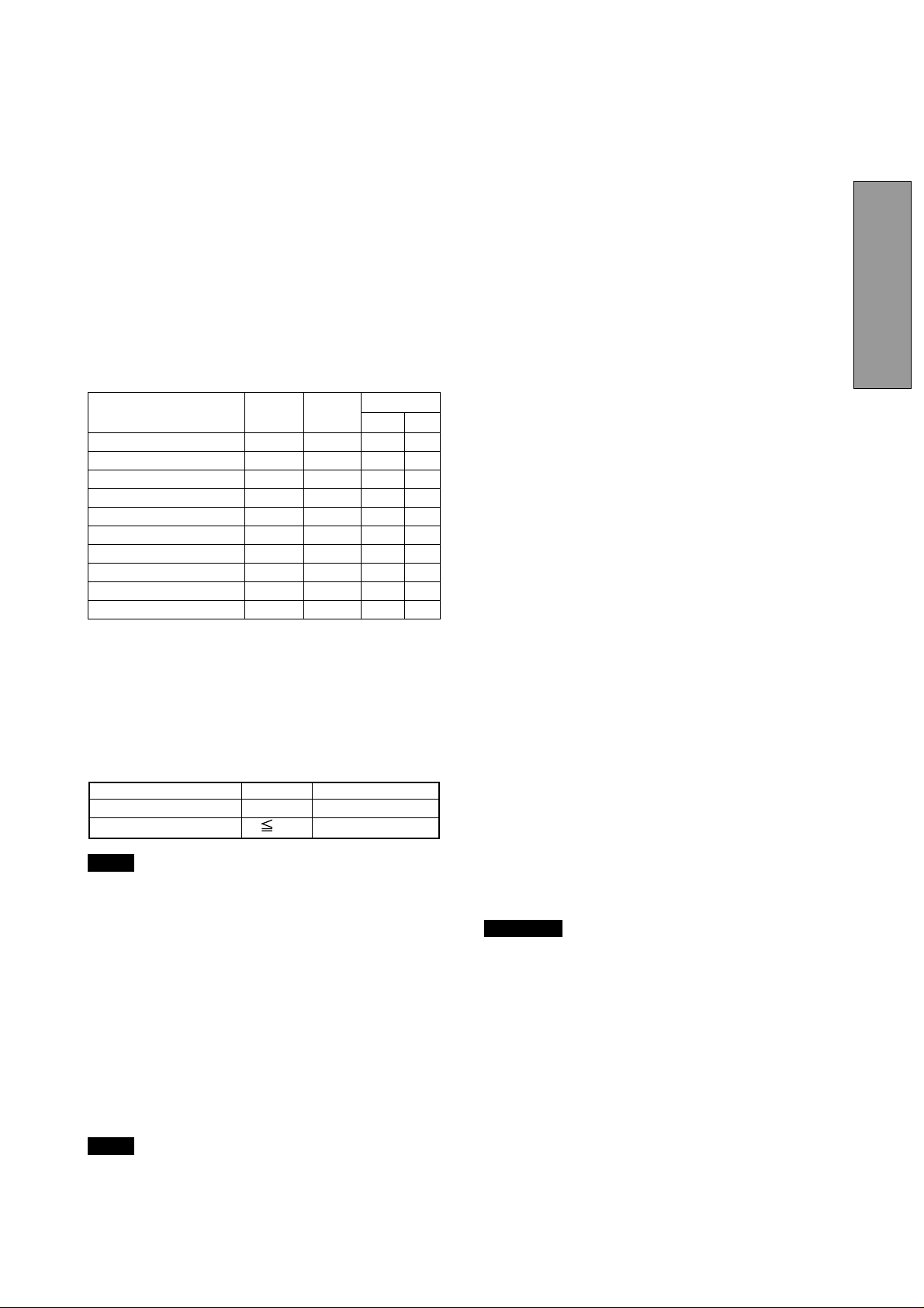
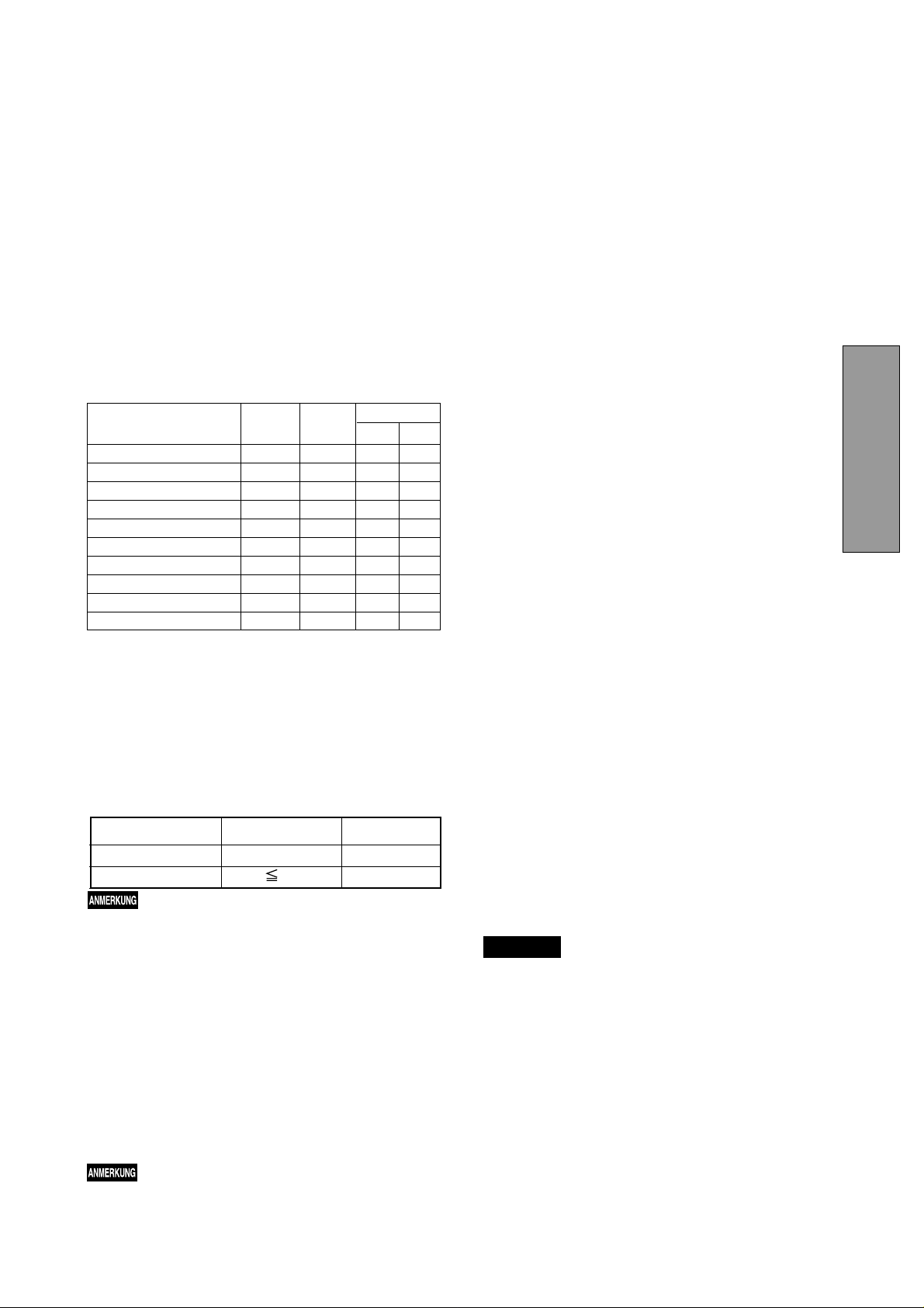
1.2 Internal Preset Memory Capability
1.5 Location Considerations
To minimize adjustment needs, the factory has preset
popular display standards into the monitor, as shown in
Table 1. If any of these display standards are detected, the
picture size and position are automatically adjusted. All of
the factory presets may be overwritten by adjusting the user
controls. This monitor is capable of automatically storing up
to 15 additional display standards. The new display information must differ from any of the existing display standards by at least 1kHz for the horizontal scan frequency or
1Hz for the vertical scan frequency or the sync signal
polarities must be different.
Table 1. Memory Buffer Factory Presets
PRESET Polarity
TIMING Fh(kHz) Fv (Hz) H V
640 x 480 N.I. 31.5 60.0 – –
800 x 600 N.I. 46.8 75.0 + +
1024 x 768 N.I. 60.0 75.0 + +
1024 x 768 N.I. 68.7 85.0 + +
1280 x 1024 N.I. 80.0 75.0 + +
1280 x 1024 N.I. 91.1 85.0 + +
1600 x 1200 N.I. 93.8 75.0 + +
1600 x 1200 N.I. 106.3 85.0 + +
1920 x 1440 N.I. 112.5 75.0 – +
1800 x 1350 N.I. 120.4 85.0 – –
1.3 Power Management Function
When setting up and using the monitor, keep the following
in mind:
ENGLISH
• For optimum viewing, avoid placing the monitor against
a bright background or where sunlight or other light
sources may reflect on the display area of the monitor.
Place the monitor just below eye level.
• Place the monitor away from strong magnetic or electromagnetic fields, such as high capacity transformers,
electric motors, large current power lines, steel pillars,
etc....
Magnetism can cause distortion in the picture and/or
color purity.
• Avoid covering the slots or openings of the monitor. Allow
adequate ventilation around the monitor so the heat from
the monitor can properly dissipate. Avoid putting the
monitor into any enclosure that does not have adequate
ventilation.
• Avoid exposing the monitor to rain, excessive moisture,
or dust, as this can cause a fire or shock hazard.
• Avoid placing the monitor, or any other heavy object, on
the power cord. Damage to the power cord can cause a
fire or electrical shock.
• When transporting the monitor, handle it with care.
The monitor has a power management function which
reduces the power consumption of the monitor when not
in use.
Power saving mode is invoked by a VESA DPMScompliant computer. Check your computer's manual for
setting this function.
Mode Power Power-On Indicator
Normal 140 W Green
Power Saving Mode 3 W Orange
NOTE
1.4 DDC
The monitor includes the VESA DDC
feature. DDC (Display Data Channel) is a communication
channel over which the monitor automatically informs the
computer system about its capabilities (e.g. each supported resolution with its corresponding timing).
DDC is routed through previously unused pins of the 15-pin
VGA connector.
The system will “Plug and Play” if both monitor and computer implement the DDC protocol.
NOTE
DDC
without USB operation
TM
2B and DDCTM2Bi
TM
2Bi is available only with connector SIGNAL-B.
1.6 Cleaning Your Monitor
When cleaning the monitor, please follow these guidelines:
• Always unplug the monitor before cleaning.
• Wipe the screen and cabinet front and sides with a soft
unspoil cloth to prevent causing imperfections.
• If the screen requires more than dusting, apply water or
neutral detergent to a soft cloth to clean the monitor
screen.
CAUTION
• Do not use benzene, thinner or any volatile substances to clean the unit as the finish may be
permanently marked.
• Never leave the monitor in contact with rubber or
vinyl for an extended time period.
• Do not spray directly on the screen as cleaner may
drip into the monitor and damage the circuitry.
• Never use an abrasive cleaner on the screen surface as this will damage the anti-reflection coating.
- 1-3 -

1.7 Unpacking
°
1.9 Quick Operation Chart
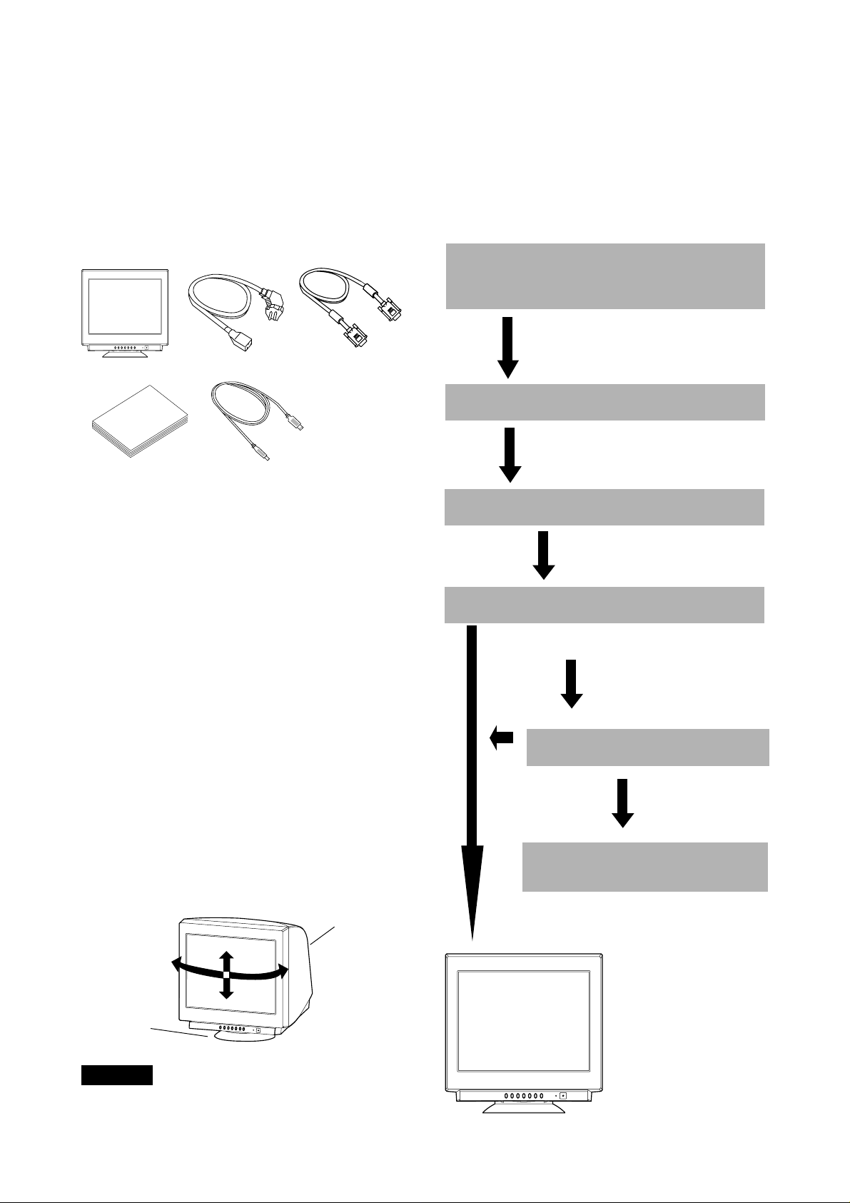
After you unpack the box you should have all of the items
indicated in Figure 1. Save the box and packing materials
in case you transport the monitor.
1
3
2
4
5
Figure 1
1. Color Monitor
2. AC Power Cord
3. Signal Cable SC-B110
4. User's Guide
(this document)
5. USB Upstream Cable
To summarize the steps in connecting your computer
with the color monitor and setting the necessary controls
and switches, refer to the chart below.
Connect the color monitor and computer with
the necessary cords and cables.
See
Section 3. INSTALLATION AND CONNECTION
Turn on the color monitor.
Turn on the computer.
Set the controls.
1.8 Tilt/Swivel Base
The monitor comes with a tilt/swivel base. This enables you
to position the monitor at the best angle and tilt for
maximum viewing comfort.
Screen Position Adjustment
Adjust the tilt and rotation of the monitor by placing your
hands at opposite sides of the case. You can adjust the
monitor 90 degrees right or left, 10 degrees up or 5 degrees
down, as shown below.
Monitor
90°
10°
90
5°
Tilt/swivel base
OK
See
Section 4. OSD(On Screen
Display) FUNCTIONS
If a problem appears.
OK
See Section 5. TROUBLESHOOTING
If the problem persists.
Call for your authorized Product Support.
Figure 2
CAUTION
Keep your fingers away from the pivot area of the tilt/swivel
base.
-1-4 -

2
2
PART NAME
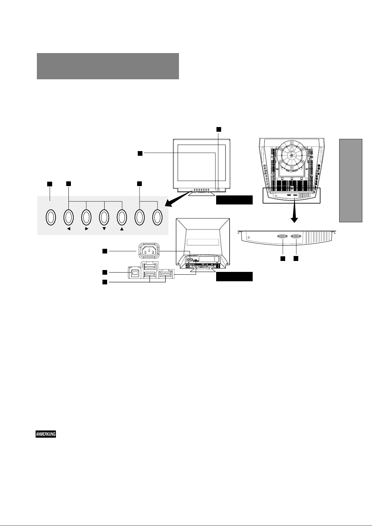
2.1 Control Names
See Figures 3 and 4 for the location of the user controls, indicator and connectors.
Each part is identified by number and is described individually.
1
1
2
3
SIGNAL A/B
OSD OFF
4 5
−+
6
SIGNAL-B SIGNAL-A
7
8
ENGLISH
9
10
Figure 3
2.2 Function
1. POWER SWITCH: A push-on / push-off switch for AC
power.
2. POWER-ON INDICATOR: This indicator illuminates
green when AC power is on, and illuminates orange
when the monitor is in the power management modes.
3. INPUT CONNECTOR SELECT/OSD OFF BUTTON:
• Without OSD screen, push to select the signal input
connector, SIGNAL A or B.
• With OSD screen, push to turn the OSD screen off.
NOTE
If only one input is used, the monitor will select it
automatically.
4. ITEM SELECT BUTTONS: Push to select the item icon.
Figure 4
5. FUNCTION ADJUST BUTTONS: Push the adjust
buttons to adjust the image on the screen.
6. AC POWER CONNECTOR
7. SIGNAL INPUT CONNECTOR (SIGNAL-A):DB9-15P
8. SIGNAL INPUT CONNECTOR (SIGNAL-B):DB9-15P
9. USB UPSTREAM PORT: To connect to USB equipped
computer.
10. USB DOWNSTREAM PORTS: To connect to USB
equipped peripherals, e.g, USB cameras, keyboards,
printers, etc.
- 1-5 -
ON
3
INSTALLA TION AND
3
CONNECTION
On the back of the monitor three kinds of plug-in connections are provided: AC power connector for the AC input,
two DB9-15P connectors for video signal input, and USB
ports for USB communication.
3.1 AC Power Connection
One end of the AC power cord is connected to the AC
power connector on the back of the monitor. The other end
is plugged into a properly grounded three-prong AC outlet.
The monitor’s auto-sensing power supply can automatically detect 100-120V AC or 220-240V AC and 50 or 60Hz.
3.2 Signal Cable Connection
The DB9-15P(VGA) connector is provided for compatible
analog RGB outputs from your computer. Apple Macintosh
computers can also be interfaced with using the optional
Mitsubishi Macintosh adapter AD-A205.
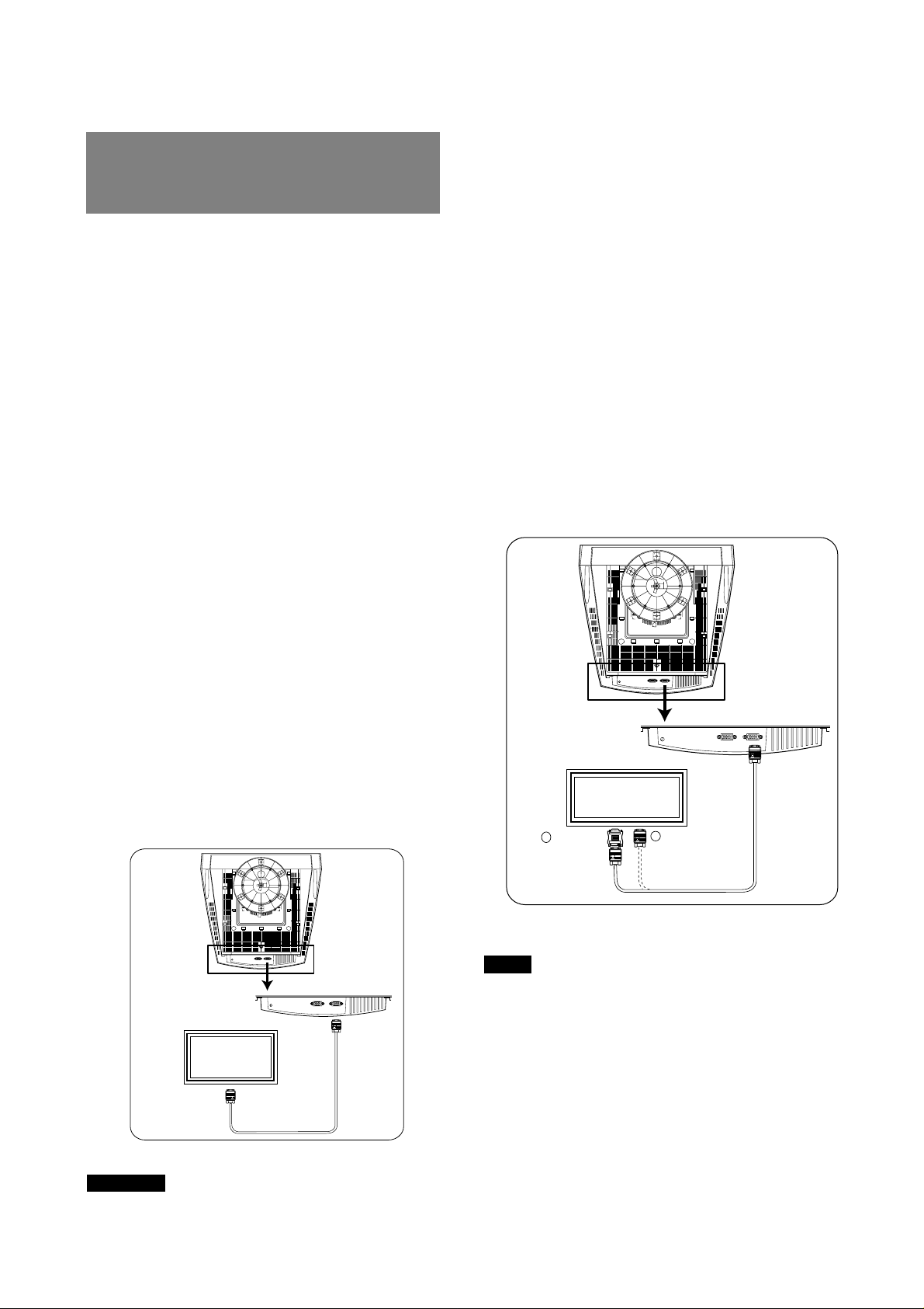
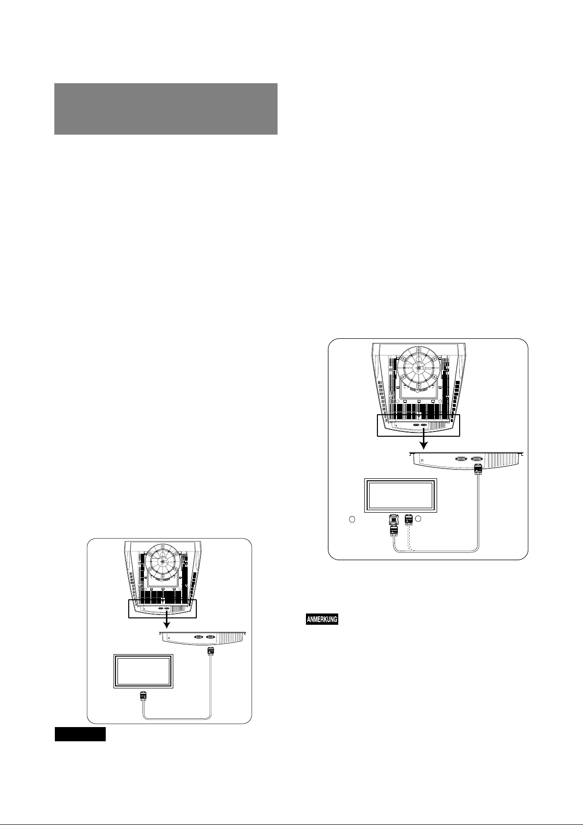
3.2.1 Connecting to Any IBM VGA Compatible System
3.2.2 Connecting to An Apple Macintosh Computer
Figure 6 shows the SC-B110 cable and AD-A205
Adapter(option) to the video port in an Apple Macintosh.
For Macintosh Adapter AD-A205, contact your dealer.
1. Power off, both the monitor and the computer.
2. Set the DIP switches of Macintosh Adapter according
to the setting chart.
(See Section 7.3 Optional Macintosh Adapter ADA205 Settings)
3. Connect the 15-pin (DB-15P) end of the AD-A205
Adapter to the straight 15-pin connector on the
Macintosh video port on the computer or on the video
board.
4. Connect the sub-miniature 15-pin (DB9-15P) end of
the AD-A205 Adapter to the SC-B110 cable.
5. Connect the other end of the SC-B110 cable to the
DB9-15P receptacle on the back of the monitor.
6. Power on the monitor, then the Macintosh.
7. After using the system, power off the monitor, then the
Macintosh.
Figure 5 shows the SC-B110 cable connection to the Video
Graphics Array (VGA) port in an IBM Personal System/2
series, or any VGA compatible system.
1. Power off, both the monitor and the computer.
2. Connect the one end of the SC-B110 cable to the
DB9-15P connector on the VGA controller card.
3. Connect the other end of the SC-B110 cable to the
DB9-15P receptacle on the back of the monitor.
4. Power on the monitor, then the computer.
5. After using the system, power off the monitor, then
the computer.
SIGNAL-B SIGNAL-A
VGA
Compatible
System
Connect to Analog RGB
Connector (D-Sub 15P)
Cable
SC-B110
®
SIGNAL-B SIGNAL-A
Cable
Apple Macintosh
SC-B110
Computer
AD-A205
ON
56
4
123
DB9-15P
1
D-SUB15P
Macintosh Adapter
AD-A205 (Option)
2
MITSUBISHI
Figure 6
NOTE
• For the Apple Macintosh Computers having a VGA
compatible port, steps 2 through 4 are not necessary.
Connect the end of the signal cable to the port directly.
• In case of Apple Macintosh G3 series, use "Control
Panel" of "Apple Menu" when selecting a resolution.
If select the resolution from "Control Bar", no screen may
be displayed and the computer may freeze.
Figure 5
CAUTION
The socket-outlet shall be installed near the equipment
and shall be easily accessible. During servicing, disconnect the plug from the socket-outlet.
-1-6 -
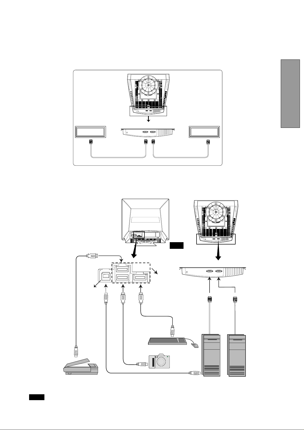
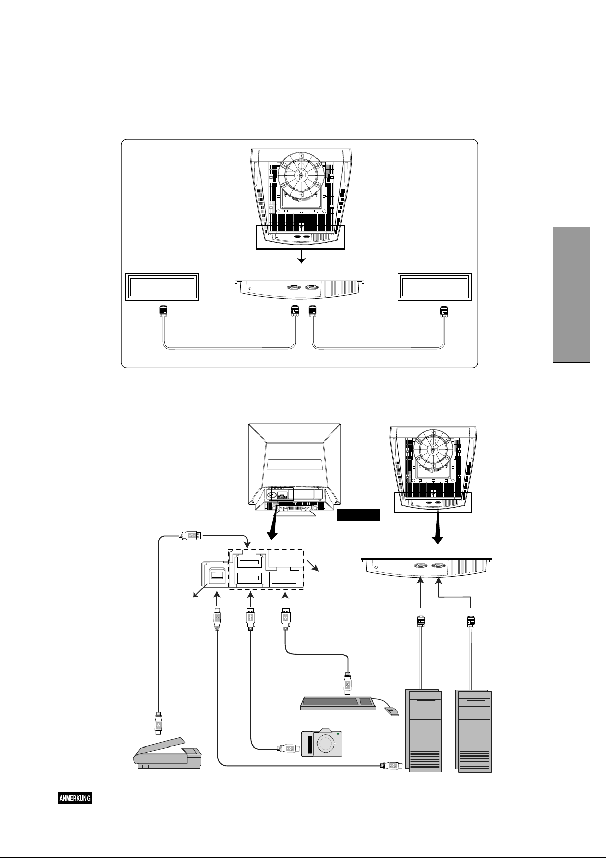
3.2.3 Connecting to two computers
Figure 7 shows the connection to two computers.
Refer to clause 3.2.1 or 3.2.2 for the connection procedure.
SIGNAL-B SIGNAL-A
Computer B
3.3 USB System Basic Application
ENGLISH
Computer A
Signal CableSignal Cable
Figure 7
USB
Cable
Scanner
Upstream
Port
Downstream
Ports
Keyboard
REAR
SIGNAL-B SIGNAL-A
Signal Cable
Camera
Computer
NOTE
The Computer is required to have Windows
®
98 or later installed and USB functions.
- 1-7 -

3.4 Installation of USB Function
The following procedure permits your computer to recognize or "enumerate"(A USB term) the USB HUB.
1. Power on the display monitor and then the computer.
®
2. Start "Enumeration" from the Windows
NOTE
• During the enumeration of USB Hub, connect the keyboard and mouse, to the computer and not to the downstream ports on the display monitor. After the enumeration, the keyboard and mouse can be used by connecting
to the downstream ports, if they are USB-compliant.
• Do not unplug the USB cable during the enumerations.
(1) Connect the computer and the display monitor with the
included USB cable. Figure 8 will appear.
(2) Click “Next” on Figure 8 to get Figure 9.
(3) Click “Finish” on Figure 9 to complete the enumeration
of USB HUB.
Desktop.
(a) Disconnect and connect the USB cable to the up-
stream port of the display monitor.
(b) Cycle power of the display monitor off then on.
NOTE
If the mark appears with “Generic USB HUB”, then
enumeration was unsuccessful. Select “Generic USB
HUB” marked with mark and click “Remove” and
“Refresh”. After that, the enumeration is automatically
started.
NOTE
The enumeration of USB HUB may be necessary for
each USB port on the computer.
Figure 8
Figure 9
You can confirm that the USB HUB is successfully enumerated with the following method.
• Open “Device Manager” tab in “System” property
under “Control Panel”. Confirm that “Generic USB
HUB” is listed in “Universal Serial Bus Controller”. If
you can’t confirm it, re-enumerate the USB HUB
again by following (a) or (b).
Figure 10
-1-8 -
4
OSD (On Screen Display)
4
FUNCTIONS
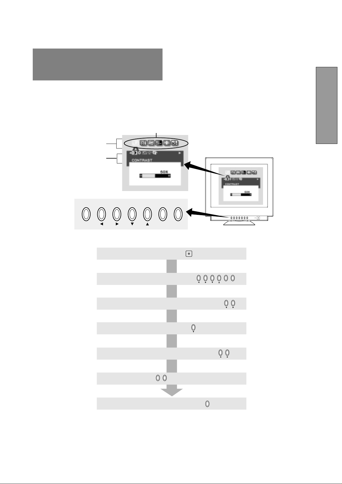
4.1 How to adjust the screen
The monitor has an OSD(On Screen Display) function.
The following procedure shows how to adjust the screen using the OSD function.
Group icon
Main Menu
Sub Menu
SIGNAL A/B
OSD OFF − +
ENGLISH
(1) Turn on the monitor by pressing
(2) Display the OSD screen by pressing
(3) Select the group icon on Main Menu by pressing
(4) Display the Sub Menu by pressing
(5) Select the item icon on Sub Menu by pressing
(6) Adjust by pressing
(7) To turn the OSD screen off, press button
If you don't press any button for the time set at "OSD TURN OFF", the OSD
will turn off automatically.
− +
SIGNAL A/B
OSD OFF
− +
- 1-9 -
+
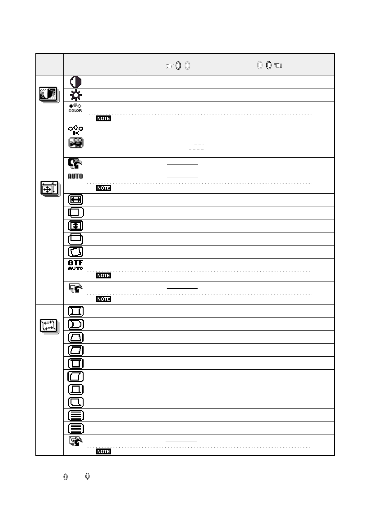
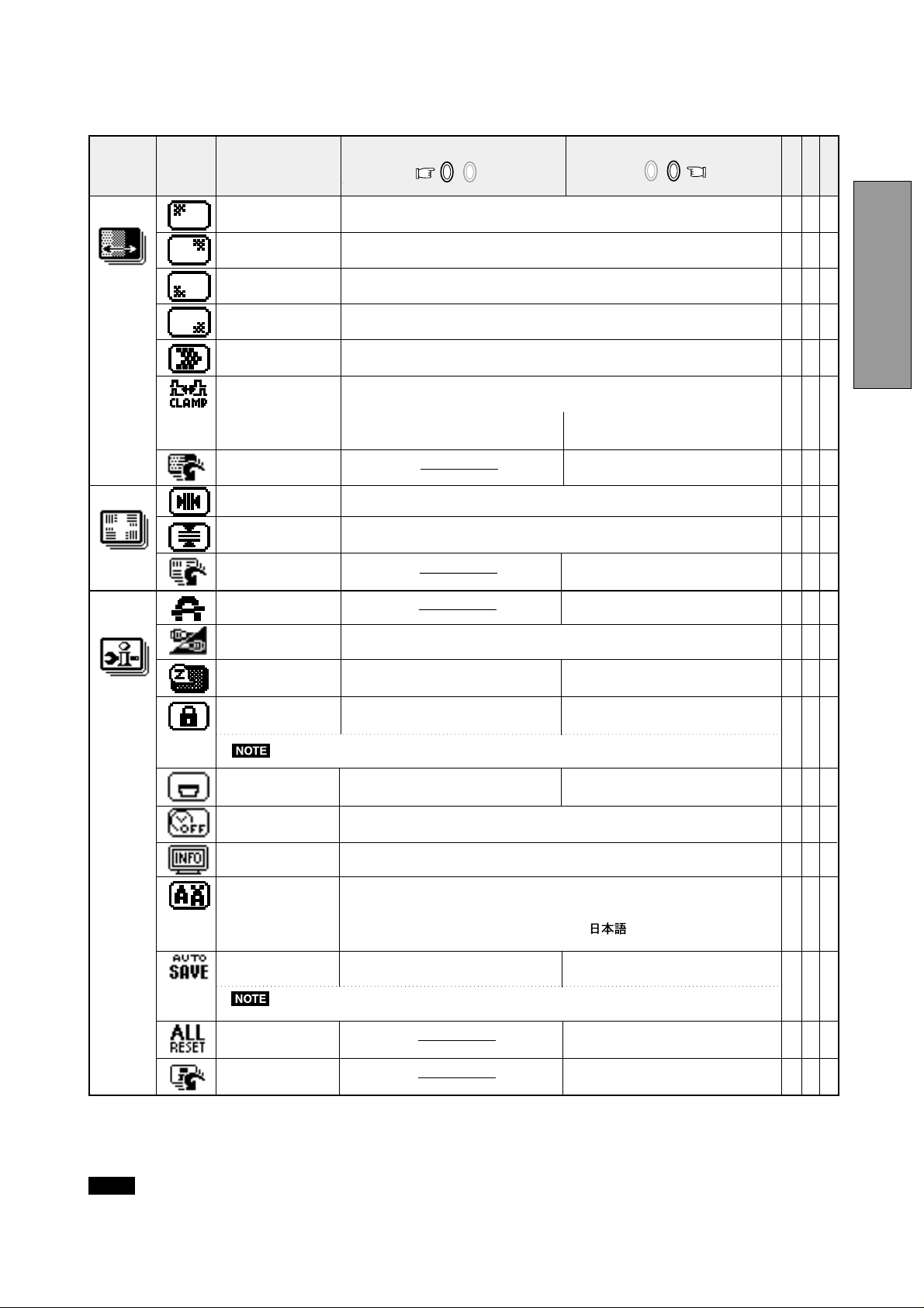
4.2 Adjustment Items
Group
Icon
Item
Icon
Item
Press the Minus Button
− +
X: Available
Press the Plus Button
ABC
− +
(COLOR)
(GEOMETRY)
CONTRAST
BRIGHT
COLOR
COLORTEMPERATURE
When selecting mode "sRGB", "COLOR TEMPERATURE", "CONTRAST" and "BRIGHT" are unavailable.
FINEPICTUREMODE
FACTORYPRESET
AUTOSIZEADJUST
"AUTO SIZE ADJUST" is unavailable when no image signal or narrow size of the image signal are inputted.
HORIZ-SIZE
HORIZ-POSITION
VERT-SIZE
VERT-POSITION
ROTATION
To decrease the contrast.
To decrease the brightness.
To select preferable display color mode. And, to adjust the color balance at the
selected color mode.
To decrease the color temperature of the
color mode selected by "COLOR"
Selects the status which provides the most pleasing image.
NORMAL MODE for normal use
TEXT MEDE for image using many letters or characters
GRAPHIC MODE for graphic and photographic images.
To increase the contrast.
To increase the brightness.
To indecrease the color temperature of the
color mode selected by "COLOR"
To restore to factory preset level.
To adjust the screen size automatically
To narrow the width of the image on the
screen.
To move the image on the screen to the
left.
To narrow the height of the image on the
screen.
To move the image down.
To rotate the image counterclockwise.
based on input timming.
To expand the width of the image on the
screen.
To move the image on the screen to the
right.
To expand the height of the image on
the screen.
To move the image up.
To rotate the image clockwise.
XXX
XXX
XXX
XXX
---
---
XX
XX
XX
XX
XXX
(DISTORTION)
GTFAUTOADJUST
"GTF AUTO ADJUST" is available when using with the computer which VESA GTF function is installed.
FACTORYPRESET
If a non-Factory Preset timing is used, "FACTORY PRESET" is unavailable.
PINCUSHION
PIN-BALANCE
KEYSTONE
KEY-BALANCE
TOP-PIN
TOP-BALANCE
BOTTOM-PIN
BOTTOM-BALANCE
VERT-LIN
VERT-LIN-BALANCE
FACTORYPRESET
If a non-Factory Preset timing is used, "FACTORY PRESET" is unavailable.
To collapse the center of the image.
To move the top and bottom of the
screen image to the right.
To decrease the width at the top of the
screen image and to increase the width at
the bottom.
To make the screen slant to the left.
To expand the width of the screen image
near the corners of top.
To make the screen slant to the left at
the top.
To expand the width of the screen image
near the corners of bottom.
To make the screen slant to the left at
the bottom.
To vertically compress the center of the
screen and expand the top and bottom.
To vertically expand the bottom of the
screen and compress the top.
To adjust the screen size automatically
based on GTF timming.
To restore to factory preset level.
To expand the center of the image.
To move the top and bottom of the
screen image to the left.
To increase the width at the top of the
screen image and to decrease the width at
the bottom.
To make the screen slant to the right.
To narrow the width of the screen image
near the corners of top.
To make the screen slant to the right at
the top.
To narrow the width of the screen image
near the corners of bottom.
To make the screen slant to the right at
the bottom.
To vertically expand the center of the
screen and compress the top and bottom.
To vertically compress the bottom of the
screen and expand the top.
To restore to factory preset level.
---
---
XX
XX
XX
XX
XX
XX
XX
XX
XX
XX
---
A. Press "FACTORY PRESET" to restore to the factory preset level.
B. Press and buttons together, to restore to the factory preset level.
C. Set data does not change by the change of the signal timing.
−
-1-10 -
X: Available
Group
Icon
(PURITY)
(CONVER.)
Item
Icon
CORNER PURITY(TL)
CORNER PURITY(TR)
CORNER PURITY(BL)
CORNER PURITY(BR)
MOIRE CANCEL LEVEL
CLAMP PULSE POSITION
FACTORY PRESET
HORIZ-CONVERGENCE
VERT-CONVERGENCE
FACTORY PRESET
DEGAUSS
Item
Press the Minus Button
− +
Press the Plus Button
− +
To adjust the purity condition on the top-left corner.
To adjust the purity condition on the top-right corner.
To adjust the purity condition on the bottom-left corner.
To adjust the purity condition on the bottom-right corner.
To decrease the level of the moire-clear wave.
To eliminate an excessive green or white-back ground that may occur when
both Sync-On green and external sync signals are applied to the monitor.
To clamp the video signal at the
front of the H-Sync pulse.
To clamp the video signal at the back of the HSync pulse. If you connect to an older
Macintosh, you may need to press plus button.
To restore to factory preset level.
To adjust the horizontal beam alignment on the full screen area.
To adjust the vertical beam alignment on the full screen area.
To restore to factory preset level.
To eliminate possible color shading
or impurity due to magnetic effects.
ABC
XXX
XXX
XXX
XXX
XX
X
---
XXX
XXX
---
---
ENGLISH
(MISC.)
INPUT
POWER SAVE
CONTROL LOCK
"BRIGHT" and "CONTRAST" are available at the locked condition.
OSD POSITION
OSD TURN OFF
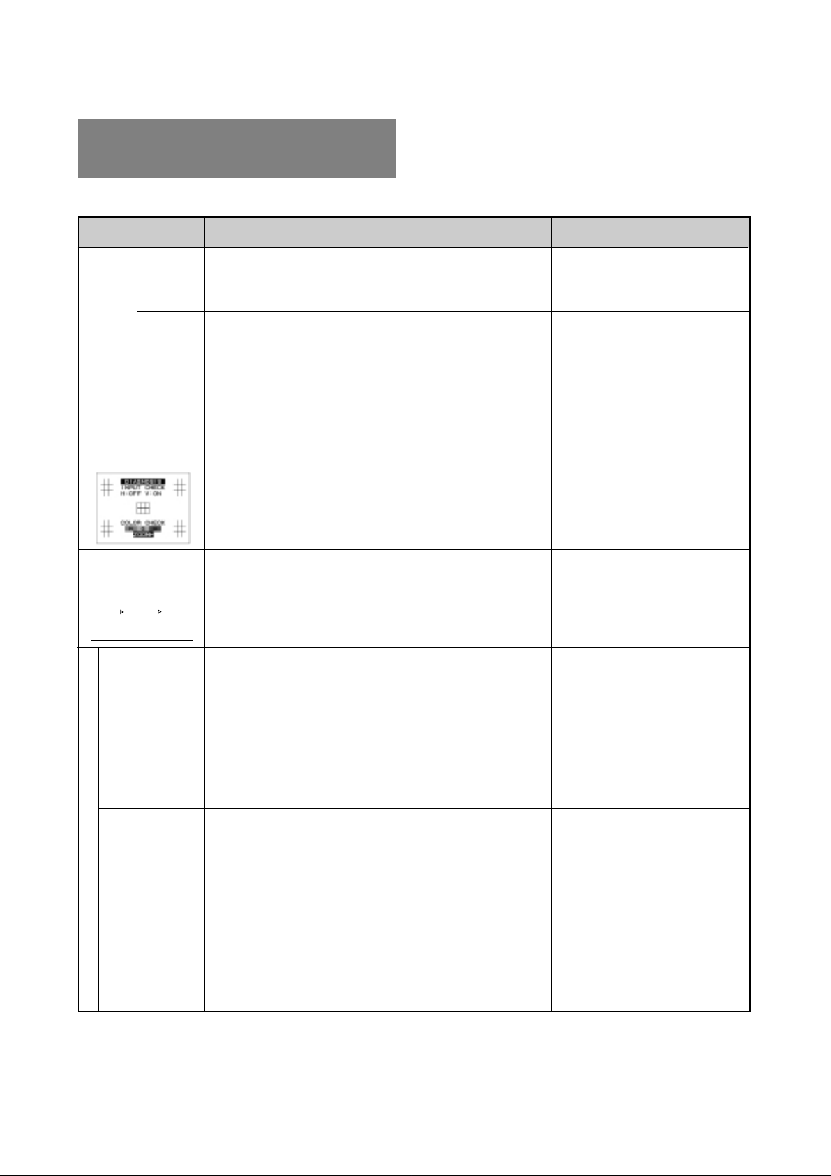
DIAGNOSIS
LANGUAGE
AUTO SAVE
When selecting "OFF", if "SAVE" is not done before the OSD screen disappeared, the new
setting is invalid.
ALL RESET
FACTORY PRESET
To select the signal input connector, SIGNAL A or
To select the constant power
consumption mode.
To unlock the OSD adjustments.
To move the OSD screen position in
a counter clockwise direction.
To select the power-save mode.
(Your computer must be set for
power management.)
To lock the OSD function except
for "BRIGHT" and "CONTRAST".
To move the OSD screen position in
a clockwise direction.
To adjust the time that the OSD screen disappear when no access.
Indicates the current scanning frequency, factory or user preset timing
number, and signal iput connector.
To choose the language used on OSD.
ENG.....English, GER.....German, FRA.....French,
ESP.....Spanish, ITA ..... Italian, .....Japanese
To save the new setting automatically.
To save the new setting with a
comfirmation message.
Restores all items to the factory
preset level.
To restore to factory preset level.
XX
X
XX
XXX
---
X
X
---
---
NOTE
If a non-Factory Preset timing is used, "FACTORY PRESET" does not work.
- 1-11 -
ATTENTION
PLEASECHANGE
SIGNALTIMING.
SIGNALFREQUENCY
ISOUTOFRANGE.
FH
24.8KHzFV
43.0Hz
5
5
TROUBLESHOOTING
Before calling your Authorized Product Support, please
check that the items below are properly connected or set.
In case of using a non-standard signal, please check the
pin assignments and the signal timing of your computer
with the specification outlined in Section 6. SPECIFICATIONS and Section 7. APPENDIX.
PROBLEM
•
LED On
(Green)
LED Off
•
•
No
picture
LED On
(Orange)
The following message appeared.
•
•
•
•
•
•
The following message appeared.
ATTENTION
SIGNALFREQUENCY
ISOUTOFRANGE.
24.8KHzFV
FH
PLEASECHANGE
SIGNALTIMING.
43.0Hz
•
ITEMS TO CHECK
Contrast and brightness controls.
Power switch.
AC power cord disconnected.
Signal cable disconnected.
Computer power switch.
Power management function is active.
Signal cable disconnected.
Computer power switch.
Power management function is active.
Input signal frequency range is too high or too low for the
monitor to synchronize with.
LOCATION
•
Front
•
Front
•
Rear
•
Rear
•
Computer
•
Press any key on the keyboard
or move the mouse.
•
Rear
•
Computer
•
Press any key on the keyboard
or move the mouse.
•
Check the specification of
graphics adapter
Display is missing, center shifts,
or too small or too
large of a display
size
Abnormal picture
No operation of
the USB devices
•
Do "FACTORY PRESET" or "ALL RESET" for a standard
signal.
•
Adjust HORIZ-SIZE, VERT-SIZE, HORIZ-POSITION, and
VERT-POSITION with non-standard signals.
•
Monitor may not be able to get full-screen image depend on
signal. In this case, please select other resolution, or other
vertical refresh timing.
•
Make sure you wait a few seconds after adjusting the size
of the image before changing or disconnecting the signal.
•
[Universal serial bus controller] is not listed in [Device
Manager].
•
[Generic USB HUB] is not listed in [Device Manager].
•
Front (OSD)
•
Front (OSD)
•
Confirm that Windows98 is installed into the computer.
•
Make sure of the cable connections.
•
Restart the computer.
•
Turn off the monitor and turn
on then.
•
Disconnect all the cables connected to the Upstream ports
and re-connect then.
-1-12 -
PROBLEM
ITEMS TO CHECK LOCATION
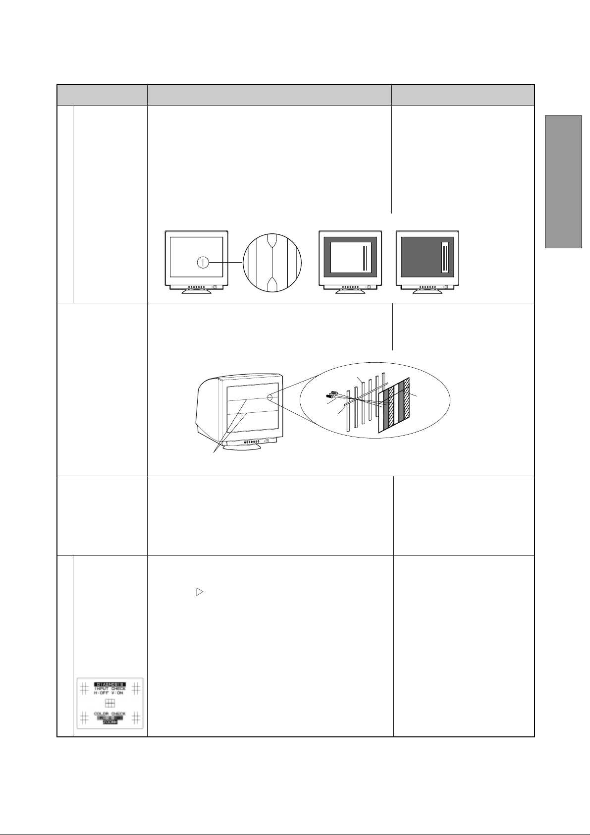
Black vertical
lines are visible
on the screen.
Abnormal Picture
Two fine horizontal
lines are visible on
the screen.
Thin vertical black lines on one or both sides of the
screen. This minor condition is caused by grille element
overlap which can occur during shipping.
Position an open white window over the affected area of
the screen and maximize the brightness and contrast
controls. This will cause localized heating of the overlap
which will clear in a few minutes. Be sure to readjust the
brightness and contrast controls back to the normal
viewing levels after this procedure.
The 2 very faint thin lines across the screen are normal.
•
They are caused by the aperture grille stabilization
filaments(Damper Wires) which are required for all
aperture grille CRTs’.
Aperture Grille
Electron Gun
Damper Wires
Shadow of
Damper Wires
ENGLISH
Shadow of Damper Wires
•
A buzzing sound
when power on.
A brief vibration or hum sound that is heard just after power
up is normal. This is caused by the automatic degaussing
function. This sound will be heard each time the monitor is
powered up from a cold start and each time the manual
degauss button is used.
This monitor has
"SELF DIAGNOSIS" to check the
operating conditions of the monitor.
If the signal cable
is disconnected or
abnormal signal is
received, the fol-
Check the color bar. (e.g RED, GREEN, BLUE)
•
CHECK the H, V signal input.
•
Push the
•
size.
Check power-on indicator on the bezel.
•
If this indicator is blinking (Orange--> Black--> Orange),
there is a possibility of failer.
Please call your Authorized Product Support.
lowing message
will appear.
SELF DIAGNOSIS FUNCTION
Aperture Grille T ype
button, the picture size is expanded to a large
- 1-13 -
6 SPECIFICATIONS
6
Size 55cm/22" (508mm/20" Viewable Image Size)
Mask type Aperture grille
Gun In-line
Deflection angle 90°
CRT Phosphors Red, Green, Blue EBU (medium short persistence)
Aperture grille pitch 0.24mm
Phosphor pitch 0.25mm
Face Plate G-WARAS
Focusing method Dynamic Beam Forming (DBF)
INPUT SIGNAL
SIGNAL INTERFACE
USB Interface •Upstream port/12Mbps
SCANNING Horizontal 30 - 121kHz
FREQUENCY Vertical 50 - 160Hz
RESOLUTION (HxV) 2048 dots x 1536 lines Non-Interlaced maximum addressable resolution format at 75Hz
WARM-UP TIME 30 minutes to reach optimum performance level
BRIGHTNESS 100cd/m2, standard full white video signal at 9300K (+ 8MPCD)
BLANKING TIME
DISPLAY SIZE 396mm x 297mm(typ.) ratio 4:3 (371mm x 297mm(typ.) ratio 5:4)
COLOR 5000K~9300K
POWER SOURCE AC100-120/220-240V±10% 50/60Hz 140W (typ.) (155W (typ.) with USB operation)
OPERATING Temperature 5 -35°C
ENVIRONMENT Humidity 10 -90%RH (without condensation)
DIMENSIONS (W)19.5inch x (H)19.4inch x (D)18.6inch / (W) 495mm x (H) 493.5mm x (D) 473mm
WEIGHT Approx. 29.7kg (65.5 lbs.)
TILT/SWIVEL Tilt Angle -5° - +10°
BASE Swivel Angle ±90°
REGULATIONS X-Ray DHHS, HWC, Röv vom 8.1, 1987
Video 0.7Vp-p analog RGB
Sync Separate H, V sync., Composite sync., or Sync on Green
Input Connectors DB9-15P X 2
Input Impedance 75Ω (video), 2.2kΩ (sync.)
Function •
Horizontal 2.0 µsec (typ.)
Vertical 400 µsec (typ.)
Safety UL1950 (UL), CSA C22.2 No.950 (C-UL)
EMC FCC Class-B, DOC Class-B
Other CE-Marking, MPR-II/TCO'91
Self-powered HUB complying with Universal Serial Bus Specification Rev.1.1
•3 Downstream ports/12Mbps, 1.5 Mbps (500mA max. per each
Downstream port)
EN60950 (TÜV-GS)
EN55022 Class-B, VCCI Class-B
EN61000-3-2, EN61000-3-3, EN55024
ISO9241-3, ISO9241-7, ISO9241-8 (TÜV-GS)
TCO '99
International E
Energy 2000 Labeling Award
Guidelines for the Suppression of Harmonics
in Appliances and General-Use Equipment
NERGY STAR Program
* This monitor is registered / certified with Model No. NSZ2107STTUW.
-1-14 -

ON
10
11
131414
12
15
7 APPENDIX
7
7.1 Monitor Signal Input Connector (DB9-15P)
ENGLISH
7.2 SC-B110 Signal Cable
(Female)
DB9-15P
MOUNTED ON THE REAR PANEL
PIN ASSIGNMENTS
Pin No. Signal
1 RED VIDEO
2 GREEN VIDEO
3 BLUE VIDEO
4 GROUND
5 DDC GROUND
6 RED GROUND
7 GREEN GROUND
8 BLUE GROUND
9NC
10 SYNC GROUND
11 GROUND
12 SDA
13 HORIZONTAL SYNC
14 VERTICAL SYNC(VCLK)
15 SCL
DDC .................. DISPLAY DATA CHANNEL
SDA................... SERIAL DATA
SCL ................... SERIAL CLOCK
NC ..................... NO-CONNECTION
or COMPOSITE SYNC
Approx. 1.8m
DB9-15P(Male)
Pin No. Signal
1
6 7
11
12
2
5
3
9
10
8
15
13
4
DB9-15P(Male)
PIN ASSIGNMENTS
1 RED
2 GREEN
3 BLUE
4 GROUND
5 DDC GROUND
6 RED GROUND
7 GREEN GROUND
8 BLUE GROUND
9NC
10 SYNC GROUND
11 GROUND
12 SDA
13 HORIZONTAL SYNC
14 VERTICAL SYNC(VCLK)
15 SCL
DDC................ DISPLAY DATA CHANNEL
SDA ................ SERIAL DATA
SCL................. SERIAL CLOCK
NC .................. NO-CONNECTION
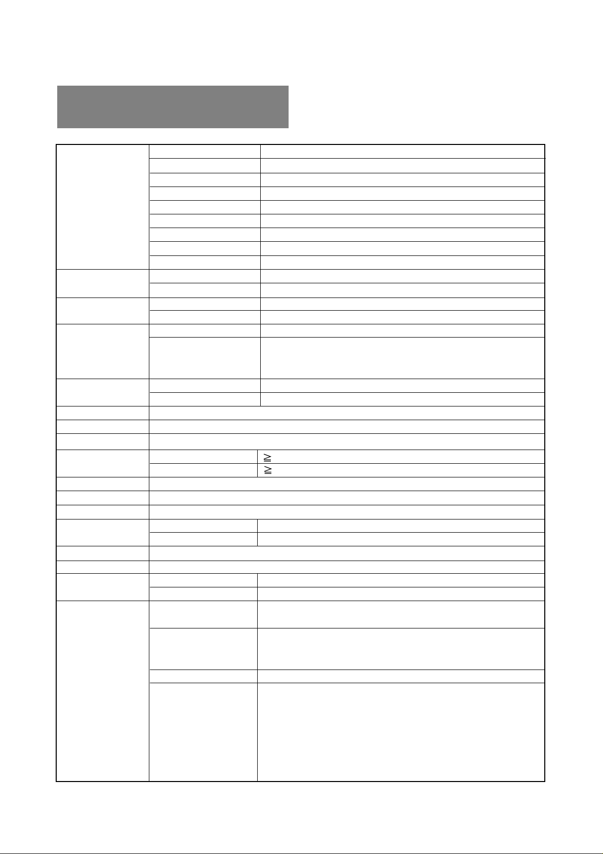
7.3 Optional Macintosh Adapter AD-A205 Settings
The AD-A205 Macintosh Adapter(option) allows you to
take an advantage of the built in video capabilities of
your Macintosh computer with the monitor.
(1) Set the dip switches of the adapter, before connect
to the computer.
Macintosh IIsi, IIci, IIvi, IIvx, LC, LC II
Dip Switches
Macintosh
Macintosh LC III, LC475, LC630
AD-A205
ON
1 2 3
M
IT
4
S
5 6
U
B
IS
H
I
Macintosh Quadra 610, 650, 700, 800, 840AV, 900, 950
Macintosh Centris 610, 650, 660AV
Display monitor
OFF
ON
Performa 6260, 6310, 6410, 6420
Power Macintosh 6100, 6100AV, 6200, 6300
Power Macintosh 7100AV, 7200, 7300, 7500, 7600
Power Macintosh 8100, 8100AV, 8500, 8600
Power Macintosh 9500, 9600
Workgroup Server 7350, 8150, 9150, 9650
(2) Set the dip switches according to the following chart.
By using the following chart, you can choose a main
resolution, quickly.
If you wish to operate by other resolution, refer to
next page; “AD-A205 Mac Adapter Setting Chart”
Apple Macintosh
Switch
ON
Switch Setting
1,2
2,4
1,2,3,4
1,2,6
Power Macintosh 4400, G3
3,4
- 1-15 -
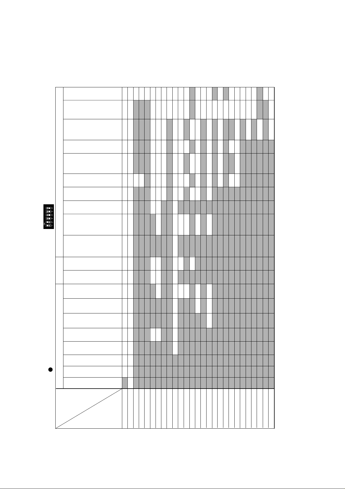
(3) “AD-A205 Mac Adapter Setting Chart” shows all available modes for Macintosh systems and all possible combinations
with the monitor.
We recommend that you use the monitor with a preset timing. (See Section 1.2 Internal Preset Memory Capability)
(4) Please refer to the instruction book of your computer about the resolution setting.
Resolution may not be changed on some computers.
>
G3
9600/300
9600/350
Server
9600/233
Workgroup
9500
7300
7500
7600
7200 4400
6200
6300
8100
VRAM
(DB-15)
Video Card
8150
9150
Server
Workgroup
9650
8500
8600
6100AV
7100AV
8100AV
6100
8100
6100AV
7350
Server
Workgroup
AV
(DB-15)
Video Card
DRAM
7100AV
8100AV
(HDI-45)
Video Port
3,4 3,4 3,4 3,4 3,4
3,43,4
1,2,6
3,4
1,2,6
1,2,6
1,2,6 1,2,6 1,2,6 1,2,61,2,61,2,63,4
3,4
3,4
3,4
3,4
3,4
3,4
3,4
3,4
3,4
3,4
3,4
3,4
1,2,6
3,4
3,4
3,4
3,4
3,4
3,4
3,4
1,2,63,4
3,4
3,4
3,4
3,4
3,4
3,4
3,4
3,4
3,4
3,4
1,2,6
1,2,6
1,2,6
1,2,6
3,4
1,2,6
1,2,6
1,2,6 1,2,6
3,4
3,4
3,4
3,4
3,4
3,4
3,4
3,4
3,4
3,4
3,4
3,43,4
3,4
3,4
1,2,6
1,2,6
1,2,6
1,2,6
1,2,6 3,4
1,2,6
3,4
3,4
3,4
1,2,6
1,2,6
1,2,6
1,2,63,41,2,61,2,6
3,4
3,4
1,2,6
1,2,6
3,4
1,2,6
3,4
3,4
3,4
3,4
3,4 3,4
3,4
1,2,61,2,6
1,2,61,2,63,4
3,4
3,4
3,4
1,2,61,2,6
3,4
1,2,6
1,2,6
3,4
3,41,2,6
1,2,6
6410
6420
Performa Power Macintosh
6260
6310
840AV
660AV
Centris
Quadra
610
Quadra
700
650
900
800
950
610
Centris
650
1,2 1,2 1,2,6 1,2,6
<Optional Macintosh AD-A205 Adapter Setting Chart
LC630 Quadra
Macintosh
LCIII
LC475
LC
LCII
IIvi
IIsi
IIvx
IIci
Set the dip switch "ON" as shown below.(Example; "1,2" )
3,4 3,4 3,4 3,4 3,4 3,4 1,2,6 1,2,6 3,4 3,4
3,4
640 x480@60Hz
RESOLUTION
1,2 1,2 1,2 1,2 1,2 1,2
640 x480@67Hz
1,2,6
1,2,6
1,2,6 1,2,63,4
3,4
3,4
640 x480@72Hz
640 x480@75Hz
640 x480@85Hz
800 x600@60Hz
800 x600@72Hz
800 x600@75Hz
800 x600@85Hz
1,2,6 3,4 3,4
1,2,63,4
3,4
2,32,3
2,42,4 2,4 2,4 2,4 1,2,6 1,2,6
832 x624@75Hz
1024 x768@60Hz
1024 x768@70Hz
1024 x768@72Hz
1024 x768@75Hz
1,2,3,4 1,2,3,4 1,2,3,4
1024 x768@85Hz
1152 x870@75Hz
1280 x960@60Hz
1280 x960@75Hz
1280 x960@85Hz
1280 x1024@60Hz
1280 x1024@75Hz
1280 x1024@85Hz
1600 x1200@60Hz
1600 x1200@65Hz
1600 x1200@67Hz
1600 x1200@70Hz
1600 x1200@75Hz
Be sure to power off the computer when you set the dip switches.
1. The resolution does not change with the computer powered on when you set the dip switches.
2. Set the dip switches by a pointed article like a pencil or ball point pen to touch end of the switch groove.
-1-16 -

INHALTSVERZEICHNIS
ACHTUNG
Das mitgelieferte Netzkabel wurde konzipiert, um
größtmögliche Sicherheit zu gewährleisten. Es darf nur
an eine ordnungsgemäß geerdete Steckdose
angeschlossen werden, um eventuelle Stromschläge
zu vermeiden.
Entfernen Sie nie die Rückwand dieses Gerätes, da Sie
sich dadurch sehr hohen Spannungen und anderen
Gefahren aussetzen können.
HERSTELLER-KONFORMITÄTSERKLÄRUNG ZUR
CE-KENNZEICHUNUNG:
Wir, NEC-Mitsubishi Electronics Display-Europe
GmbH., erklären in alleiniger Verantworlung, daß das
Produkt auf das sich diese Erklärung bezieht, mit der/
den folgenden Normen oder normativen Dokumenten
übereinstimmt:
EN60950
EN55022 Klasse B
EN61000-3-2
EN61000-3-3
EN55024
Gemäß den Bestimmungen der Richtlinien:
73/23/EEC Niederspannungsrichtlinie
89/336/EEC EMV Richtlinie
1. EINLEITUNG ....................................................... 2-2
1.1 Eigenschaften .......................................... 2-2
1.2 Interne Speicherfähigkeit ......................... 2-3
1.3 Power Management Funktion .................. 2-3
1.4 DDC ......................................................... 2-3
1.5 Betriebshinweise ...................................... 2-3
1.6 Reinigung Ihres Monitors ......................... 2-3
1.7 Auspacken ............................................... 2-4
1.8 Dreh-/ Kippfuß.......................................... 2-4
Justierung des Bildschirms ...................... 2-4
1.9 Kurzinstallationsanweisung...................... 2-4
2. BEDIENELEMENTE UND ANSCHLÜSSE.......... 2-5
2.1 Bedienelemente ....................................... 2-5
2.2 Funktion ................................................... 2-5
3. INSTALLATION UND ANSCHLUß...................... 2-6
3.1 Anschluß des Netzkabels......................... 2-6
3.2 Anschluß des Signalkabels ...................... 2-6
3.2.1 Anschluß an ein PC-System ............. 2-6
3.2.2
Anschluß an Apple Macintosh Computer
.......................................................... 2-6
3.2.3 Anschluß an zwei Computer ............. 2-7
3.3 USB System Anwendungen..................... 2-7
3.4 Installation der USB Funktion................... 2-8
DEUTSCH
ACHTUNG!
Dieses Produkt ist nicht für den Gebrauch in
Zusammenhang mit lebenserhaltenden Geräten
geeignet und die NEC-Mitsubishi Electronics DisplayEurope GmbH macht keinerlei gegensätzliche
Darstellungen. Lebenserhaltende Geräte sind solche,
die zum Messen, Diagnostizieren oder für die
Auswertung von Gewebe, Systemen oder Funktionen
des menschlichen Körpers benutzt werden; oder andere
Geräte die angewendet werden, um das Leben oder
die Gesundheit zu unterstützen oder zu erhalten.
Warenzeichen
IBM, PC, PS/2, PS/V, Personal System/2 sind eingetragene
Warenzeichen der International Business Machines Corp.
Apple Macintosh, Quadra sind eingetragene Warenzeichen der
Apple Computer, Inc.
UNIX ist ein eingetragenes Warenzeichen in den Vereinigten
Staaten und anderen Ländern, lizensiert ausschließlich durch
X/Open Company Limited.
E
NERGY STAR
© 2000 NEC-Mitsubishi Electronics Display-Europe GmbH
ist eine eingetragenes U.S. Warenzeichen.
4. FUNKTIONSKONTROLLE .................................. 2-9
4.1 Einstellen des Monitors ............................ 2-9
4.2 Einstellfunktionen ..................................... 2-10
5. STÖRUNGSSUCHE............................................ 2-12
6. SPEZIFIKATIONEN............................................. 2-14
7. ANHANG .......................................................... 2-15
7.1
Eingangsanschluß des Monitors (DB9-15P)
.......................................................... 2-15
7.2 Signalkabel SC-B110 ............................... 2-15
7.3 Einstellung des optionalen Macintosh
Adapters AD-A205 ................................... 2-15
- 2-1 -

1
EINLEITUNG
1
Wir gratulieren Ihnen zu dem Kauf des hochauflösenden
Farbmonitors. Wir entwickelte diesen Monitor mit dem Ziel,
Ihnen jahrelang eine zuverlässige, störungsfreie Benutzung
zu ermöglichen.
Dieses Handbuch zeigt lhnen den Anschluß, die Einstellung
und die Pflege lhres Monitors. Außerdem sind technische
Spezifikationen und ein Kapitel zur Störungssuche
enthalten.
1.1 Eigenschaften
Der Monitor ist ein intelligenter 55cm/22" (508mm/20"
Sichtbarer Bildgröße) Monitor, der zu den meisten analogen
RGB (Rot, Grün, Blau) Bildschirmstandards kompatibel ist.
Er ermöglicht die Wiedergabe von Texten und
Grafikdarstellungen sowohl auf PC-als auch auf MacintoshSystemen.
• Die große Kompatibilität des Monitors ermöglicht den
Wechsel des Grafikadapters oder der Software ohne
den Kauf eines neuen Monitors.
• Das Auto-Scanning wird digital über den Mikroprozessor
gesteuert. Der Monitor synchronisiert sich automatisch
auf alle horizontalen Frequenzen zwischen 30kHz und
121kHz und auf alle vertikalen Frequenzen zwischen
50Hz und 160Hz. Die Mikroprozessorsteuerung des
Monitors erlaubt den Betrieb des Monitors in jedem
Frequenzmodus mit der Präzision eines Fest-FrequenzMonitors.
• Um dem Benutzer Installation und Einstellung so einfach
wie möglich zu gestalten, ist der Monitor mit einem
Bildschirmmenu (On Screen Display, OSD) für alle
Einstellfunktionen ausgestattet.
• Für den Einsatz in den verschiedensten Anwendungen
erfüllt der Monitor die Standards UL 1950, CSA C22.2
Nr. 950 und EN60950 für Sicherheit, FCC Klasse B,
VCCI Klasse B und EN55022 Klasse B für EMI, die
MPR-II Richtlinien sowie die Standards ISO9241-3,
ISO9241-7 und ISO9241-8 für Ergonomie. Dieser
Monitor erfüllt die Richtlinien der TCO '99-Norm für den
umweltfreundlichen Gebrauch.
• Die weltbekannte DIAMONDTRON NF Bildröhre mit
verbessertem Fokus und Konvergenz für ein extrem
scharfes und reines Bild.
• Dieser Monitor entspricht den DDC
Spezifikationen der Video Electronics Standards Association (VESA
(bzw, einer Grafikkarte), der die DDC
Funktion unterstützt, werden alle Anpassungen
automatisch durchgeführt.
• Eine feine 0.24mm Streifenmaske mit einer maximalen
Auflösung von 2048 x 1536 Bildpunkten.
• Akiver USB-Hub mit 1 Upstream-und 3 DownstreamAnschlüssen.
TM
). Bei Verwendung eines Computers
TM
2B/2Bi(EDID)
TM
1/2B(EDID)
• Neben einer Reihe von bereits voreingestellten
Bildschirmstandards bietet der Monitor auch die
Möglichkeit, benutzerabhängige Einstellungen für diese
und weitere Timings abzuspeichern.
• Der Monitor besitzt die Funktion "AUTO-GRÖßENEINST." (Automatische Größenanpassung) zur
Optimierung der Größe und Entzerrung bei Verwendung
eines nicht vordefinierten Timings.
• Der Monitor erlaubt eine maximale horizontale Auflösung
von 2048 Bildpunkten und eine maximale vertikale
Auflösung von 1536 Linien bei IBM-basierenden
Systemen und ist somit auch für fensterorientierte
Benutzeroberflächen hervorragend geeignet.
• Aufgrund der analogen Signaleingänge verfügt der
Monitor über eine unbegrenzte Farbpalette, die Ihren
Vorstellungen entsprechend abgeglichen werden kann.
• Zur Energieeinsparung verfügt der Monitor über ein voll
dem VESA
entsprechendes Power Management-System. Für die
automatische Abschaltung muß der Monitor an ein
System angeschlossen sein, weches einem dieser
Standards entspricht (Für die korrekte Einstellung
beachten Sie bitte die Bedienungshinweise zu Ihrem
PC und/oder Ihrer Grafikkarte).
TM
-DPMSTM, NUTEK und Energy Star
- 2-2 -
1.2 Interne Speicherfähigkeit
Einstellaufwand für den Benutzer so gering wie möglich zu
halten, wurden werksseitig bereits die in Tabelle 1
aufgelisteten Bildschirmstandards abgespeichert. Erkennt
der Monitor einen dieser Standards, werden Bildlage und größe automatisch justiert. Diese Voreinstellungen können
unter Benutzung der Bedienelemente überschrieben
werden. Zusätzlich zu den werksseitig eingestellten Timings können bis zu zwölf weitere Timings abgespeichert
werden. Um als 15 Timing erkannt zu werden, muß das
neue Videosignal in der Horizontalfrequenz um mindestens
1KHz, in der Vertikalfrequenz um mindestens 1Hz oder in
der Polarität der Synchronsignale von sämtlichen bereits
abgespeicherten Timings abweichen.
Tablle 1. Werksseitig Voreinstellungen
VOREINGESTELLTES Polarität
TIMING Fh(kHz) Fv (Hz) H V
640 x 480 N.I. 31.5 60.0 – –
800 x 600 N.I. 46.8 75.0 + +
1024 x 768 N.I. 60.0 75.0 + +
1024 x 768 N.I. 68.7 85.0 + +
1280 x 1024 N.I. 80.0 75.0 + +
1280 x 1024 N.I. 91.1 85.0 + +
1600 x 1200 N.I. 93.8 75.0 + +
1600 x 1200 N.I. 106.3 85.0 + +
1920 x 1440 N.I. 112.5 75.0 – +
1800 x 1350 N.I. 120.4 85.0 – –
1.5 Betriebshinweise
Bitte beachten Sie bei der Aufstellung und dem Betrieb
Ihres Monitors folgende Hinweise:
• Stellen Sie den Monitor nicht vor einem hellen
Hintergrund oder dort auf, wo das Sonnenlicht oder
andere helle Lichtquellen direkt auf den Monitor
scheinen, um eine Anstrengung der Augen zu
vermeiden. Um eine höchstmögliche Ergonomie zu
gewährleisten, sollte der Monitor so aufgestellt werden,
daß er sich unterhalb der Augenhöhe befindet.
Installieren Sie den Monitor nicht in der Nähe von Geräten,
•
die starke magnetische oder elektromagnetische
erzeugen, wie z.B. Hochleistungstransformatoren,
Elektromotoren, Starkstromleitungen, Stahlsäulen usw.
Magnetische Felder können zu Farbveränderungen
und/oder zu Bildverzerrungen führen.
• Decken Sie die Entlüftungsöffnungen des Monitors
nicht zu. Sorgen Sie für ausreichende Belüftung, damit
die im Monitor entstehende Wärme abgeführt werden
kann.
• Schützen Sie den Monitor vor Regen, Feuchtigkeit und
Staub, um einen Brand oder Stromstöße zu vermeiden.
• Achten Sie darauf, daß weder der Monitor, noch ein
anderer schwerer Gegenstand auf dem Netzkabel
stehen. Eine Beschädigung des Netzkabels kann
einen Brand oder Stromstöße verursachen.
Felder
DEUTSCH
1.3 Power Management Funktion
Dieser Monitor besitzt eine Energiesparfunktion, welche
die Leistungsaufnahme reduziert, wenn der Monitor nicht
benutzt wird. Diese werden durch einen Computer aktiviert,
der den VESA-DPMS Richtlinien entspricht. Zur Aktivierung
dieser Funktion beziehen Sie sich bitte auf das Handbuch
zu Ihrem Computer.
Modus
Normal 140 W Grün
Energiesparmodi 3W
Ohne USB-Betrieb
1.4 DDC
Dieser Bildschirm ist mit der DDC
ausgestattet. DDC (Display Data Channel) ist ein
Übertragungskanal, über den der Bildschirm dem Computer automatisch seine Leistungsmerkmale mitteilt (z.B.
jeder unterstützte Bildschirmmodus mit dem
entsprechenden Timing).
DDC benutzt einen Stift des 15-Stift-VGA-Steckers, der
vorher nicht verwendet wurde. Das System wird die “Plug
& Play”-Funktion nur dann ausführen, wenn sowohl
Bildschirm als auch Computer mit der DDC Funktion
ausgerüstet sind.
TM
2Bi ist nur über den Anschluss SIGNAL-B
DDC
verfügbar.
Leistungsaufnahme Betriebsanzeige
Bernsteinfarben
TM
2B/ DDCTM2Bi Funktion
• Behandeln Sie den Monitor vorsichtig beim Transport.
1.6 Reinigung Ihres Monitors
Beachten Sie bei der Reinigung Ihres Monitors bitte folgende
Hinweise:
• Ziehen Sie vor der Reinigung immer den Netzstecker
aus der Steckdose.
• Reinigen Sie den Bildschirm und das Gehäuse mit
einem weichen Tuch.
• Verwenden Sie bei einer stärkeren Verschmutzung
des Bildschirms ein weiches Tuch mit HaushaltsFensterreiniger für die Reinigung.
ACHTUNG
• Reinigen Sie das Gerät nicht mit Benzol, Verdünnern
oder anderen flüchtigen Stoffen, da die Oberfläche
durch diese Stoffe beschädigt werden könnte.
• Vermeiden Sie längeren Kontakt mit Gummi- oder
Vinylprodukten.
• Sprühen Sie Reinigungsmittel niemals direkt auf den
Monitor, da übermäßige Flüssigkeit in den Monitor
eindringen und zu Schäden führen könnte.
• Benutzen Sie niemals ein Scheuermittel auf der
Bildröhrenoberfläche, da dies zur Beschädigung der
Anti-Reflexionsbeschichtung führt.
- 2-3 -
1.7 Auspacken
°
Nach dem Auspacken lhres Farbmonitors sollten alle in
Bild 1 aufgeführten Teile vorhanden sein. Verwahren Sie
den Originalkarton und das Verpackungsmaterial, falls Sie
den Monitor später versenden oder transportieren müssen.
1.9 Kurzinstallationsanweisung
Die nachfolgende Abbildung erläutert den Anschluß
lhres Computers und Adapters an den Farbmonitor und
die Einstellung des Monitors.
1
4
23
5
Bild 1
1. Hochauflösende Farbmonitor
2. Netzkabel
3. Kabel: SC-B110
4. Bedienungsanleitung (Dieses Dokument)
5. USB Upstream Kabel
1.8 Dreh-/Kippfuß
Der Monitor wird mit einem Dreh-/Kippfuß geliefert. Er
ermöglicht die Ausrichtung des Monitors nach den
Anforderungen des Benutzers für größtmögliche Ergonomie.
Schließen Sie den Monitor mit den entsprechenden
Kabeln an den PC an.
Bitte beachten Sie sektion
3. INSTALLATION UND ANSCHLUß
Stellen Sie den Farbmonitor ein.
Schalten Sie den Computer ein.
Stellen Sie den Monitor nach lhren Bedürfnissen ein.
Bitte beachten Sie sektion
4. FUNKTIONSKONTROLLE
OK
Bei Auftreten eines Problems
OK
Bitte beachten Sie sektion
5. STÖRUNGSSUCHE
Justierung des Bildschirms
Fassen Sie den Bildschirm an den gegenüberliegenden
Seiten, an und stellen Sie den gewünschten Dreh- und
Kippwinkel ein. Sie können den Monitor um 90 Grad
nach rechts oder links drehen, um 10 Grad nach oben
und um 5 Grad nach unten kippen.
Monitor
90°
10°
90
5°
Dreh-/Kippfuß
Bild 2
ACHTUNG
ACHTUNG
Bitte die Finger nicht in die Nähe der beweglichen Teile
des Dreh-/Kippfusses bringen, da sonst Einklemmgefahr
besteht.
Läßt sich das Problem
nicht beheben
Wenden Sie sich an den autorisierten
Product Support.
- 2-4 -
2
BEDIENELEMENTE
2
UND ANSCHLÜSSE
2.1 Bedienelemente
Bild 3 und 4 zeigen die Position der Bedienelemente und Anzeigen. Jedes Bedienelement ist mit
einer Ziffer gekennzeichnet und einzeln beschrieben.
1
1
3
SIGNAL A/B
OSD OFF
4 5
6
9
10
Bild 3
2
−+
VORDERSEITE
RÜCKSEITE
SIGNAL-B SIGNAL-A
7
8
Bild 4
DEUTSCH
2.2 Funktion
1. NETZSCHALTER: Schaltet das Gerät ein bzw. aus.
2. BETRIEBSANZEIGE: Diese Anzeige leuchtet auf, wenn
der Monitor eingeschaltet ist. und leuchtet
bernsteinfarben, wenn sich der Monitor im EnergiesparModus befindet.
3. INPUT CONNECTOR SELECT/OSD OFF:
• Ohne Bildschirmmenü: Eingangsanschluss SIGNAL A oder B durch Drücken auswählen.
• Mit Bildschirmmenü: Drücken deaktiviert das
Bildschirmmenü.
Ist nur ein Eingang belegt, wird dieser automatisch
vom Monitor ausgewählt.
4. AUSWAHLTASTE: Drücken Sie diese Taste, um die
gewünschte Einstellungsfunktion auszuwählen.
5. EINSTELLTASTEN: Mit diesen Tasten justieren Sie
die gewünschte Bildeinstellung.
6. NETZBUCHSE
7. SIGNAL EINGANGSBUCHSE (SIGNAL A): DB9-15P
8. SIGNAL EINGANGSBUCHSE (SIGNAL B): DB9-15P
9. UPSTREAM ANSCHLUß: Zum Anschluß an die USB-
Schnittstelle eines Computers, um die Monitor-EinstellSoftware nutzen zu können.
10.USB DOWNSTREAM ANSCHLUß: Zum Anschluß
von USB Peripheriegeräten, wie z.B. USB Kameras,
Tastatur, Drucker, etc.
- 2-5 -
3
ON
3
INSTALLATION
UND ANSCHLUß
Auf der Rückseite des Monitors befinden sich vier
Anschlüsse: Die Netzanschlußbuchse für den
Netzanschluß, zwei DB9-15P-Buchsen zum Anschluß der
Videosignale und ein USB-Upstream-Anschluß für die
Monitor-Einstell-Software.
3.1 Anschluß des Netzkabels
Stecken Sie das eine Ende des Netzkabels in die dafür
vorgesehene Buchse auf dem Anschlußfeld auf der
Rückseite des Monitors und das andere in eine
ordnungsgemäß geerdete Netzsteckdose. Das
automatische Schaltnetzteil des Monitors stellt sich
selbständig auf die Netzspannung von entweder 100-120V
AC oder 220-240V AC, 50 oder 60Hz ein.
3.2 Anschluß des Signalkabels
Das beigefügte Signalkabel ist mit einem DB9-15P Stecker
für den Anschluß an die VGA-kompatiblen RGB-Ausgänge
Ihres PC ausgestattet. APPLE Macintosh Computer können
unter Verwendung des optional erhältlichen Mitsubishi
Macintosh Adapters angeschlossen werden.
3.2.2 Anschluß an Apple Macintosh Computer
Bild 6 zeigt den Anschluß an das Grafikboard eines Apple
Macintosh mittels des Kabels SC-B110 und optionalen
Adapters AD-A205.
1. Schalten Sie den Monitor und den Rechner aus.
2. Stellen Sie die DIP Schalter am Macintosh Adapter
der Tabelle entsprechend ein.
(Bitte beachten sie sektion 7.3 Einstellung des
optionalen Macintosh Adapters AD-A205)
3. Schließen Sie das 15-polige Ende (DB-15P) des
Adapters AD-A205 an die 15-polige Buchse an
dem integrierten Macintosh Grafikadapter oder der
Zusatzgrafikkarte an.
4. Verbinden Sie das 15-polige Sub-Miniatur-Ende
(DB9-15P) des Adapters AD-A205 mit dem Kabel
SC-B110 (P/C).
5. Verbinden Sie das Monitorende (D/M) des Kabels
SC-B110 mit der 15-poligen Buchse des Monitors.
6. Schalten Sie zuerst den Monitor, dann den
Macintosh ein.
7. Wenn Sie das System verlassen, schalten Sie erst
den Monitor, dann den Macintosh aus.
3.2.1 Anschluß an ein PC-System
Bild 5 zeigt den Anschluß des Signalkabels SC-B110 an
den VGA-Anschluß eines PC der IBM Personal System/2
Serie oder jedes VGA-kompatiblen Systems.
1. Schalten Sie den Monitor und den PC aus.
2. Schließen Sie das Computerende des Kabels SCB110 an die 15-polige Buchse an der VGA-Grafikkarte
an.
3. Schließen Sie das Monitorende des Kabels SC-B110
an die 15-polige Buchse (DB9-15P) des Monitors an.
4. Schalten Sie erst den Monitor, dann den ein PC.
5. Wenn Sie das System verlassen, schalten Sie erst
den Monitor, dann den PC.
SIGNAL-B SIGNAL-A
VGA
ACHTUNG
Kompatible
Verbindung über
analogen RGBAnschluss
(D-Sub 15P)
System
Bild 5
Kable
SC-B110
Die Stromversorgung dieses Monitors bleibt auch bei
ausgeschaltetem Gerät aktiv. Daher sollte sich die
Netzsteckdose in der Nähe des Gerätes befinden und
leicht zugänglich sein.
®
SIGNAL-B SIGNAL-A
Apple Macintosh
Computer
AD-A205
ON
56
4
123
DB9-15P
1
D-SUB15P
Macintosh Adapter
AD-A205 (Optional)
2
MITSUBISHI
Bild 6
• Falls lhr Apple Macintosh Computer mit einem VGAkompatiblen Anschluß ausgestattet ist, entfallen die
Schritte 2 bis 4. Schließen Sie in diesem Fall das
Signalkabel direkt an Anschluß an.
• Bitte gehen Sie in die Kontrollfelder des Apple Menüs,
wenn Sie die Auflösung ändern möchten. (Macintosh
G3 Serie). Wenn Sie die Auflösung von der Kontrolleiste
aus ändern, kann es sein, daß kein Bild dargestellt wird
und der Computer "eingefroren" wird.
Kabel
SC-B110
- 2-6 -
3.2.3 Anschluß an zwei Computer
Abbildung 7 zeigt das Anschließen an zwei Computer.
Das Anschließen wird in Abschnitt 3.2.1 bzw. 3.2.2 beschrieben.
SIGNAL-B SIGNAL-A
Computer B
Bild 7
DEUTSCH
Computer A
Signal KabelSignal Kabel
3.3 USB System Anwendungen
USB
Kabel
Upstream
Port
RÜCKSEITE
Downstream
Ports
SIGNAL-B SIGNAL-A
Signal Kabel
Keyboard
Camera
Scanner
Der Computer muss mit Windows® 98 oder höher und USB ausgestattet sein.
- 2-7 -
Computer
 Loading...