

Page 1
ENGLISH
Plasma Display
USER'S MANUAL
Thank you for purchasing the Plasma Display.
Before using your Display, please read the "SAFETY INSTRUCTIONS"
and this "USER'S MANUAL" carefully to learn how to operate the
Display properly. Keep this manual in a safe place. You will find it
useful in the future.
Notes on lnstallation
This product is marketed with the assumption that it is to be
installed by qualified personnel with relevant skills and
competence. It is recommended to consult with an installation
specialist or your d ealer install and s et up the product. We cannot
assume liabilities for damages caused by improper installation or
mounting, misuse, modifications or natural disasters.
1
Page 2
SAFETY POINTS THAT YOU SHOULD KNOW ABOUT YOUR Plasma Display
Our reputation has been built on the quality, performance, and ease of service of Plasma Display .
Safety is also foremost in our minds in the design of these units. To help you operate these products properly, this section illustrates safety
tips which will be of benefit to you. Please read it carefully and apply the knowledge you obtain from it to the proper operation of your
Plasma Display .
IMPORTANT SAFETY INSTRUCTIONS
Follow all warnings and instructions marked on this Plasma Display .
CAUTION: TO REDUCE THE RISK OF ELECTRIC SHOCK,
REFER SERVICING TO QUALIFIED SERVICE PERSONNEL.
WARNING:
CAUTION
RISK OF ELECTRIC SHOCK
DO NOT REMOVE THE COVER (OR BACK).
NO USER SERVICEABLE PARTS INSIDE.
DO NOT OPEN
z TO AVOID FIRE OR ELECTROCUTION, DO NOT EXPOSE THIS MONITOR TO RAIN OR MOISTURE.
zTHE MONITOR SHOULD NOT BE EXPOSED TO DRIPPING OR SPLASHING AND OBJECTS SUCH AS
VASES FILLED WITH LIQUIDS, SHOULD NOT BE PLACED ON THE DISPLAY.
NOTE:
z There are no user serviceable parts inside the DISPLAY.
z Model information and serial numbers are indicated on the rear side of the DISPLAY.
The lightning flash with arrowhead symbol, within an
equilateral triangle, is intended to alert the user to the
presence of uninsulated "dangerous voltage" within the
product's enclosure that may be of sufficient magnitude to
constitute a risk of electric shock to persons.
The exclamation point within an equilateral triangle, is
intended to alert the user to the presence of important
operating and maintenance (servicing) instructions in the
literature accompanying the appliance.
ENGLISH
CAUTION:
MODIFICATIONS:
Adjust only those controls that are covered in these instructions, as improper changes or modifications not
expressly approved by us could void the user's authority to operate the DISPLAY.
The FCC requires that the user be notified that any changes or modifications made to this device, that are not
expressly approved by us may void the user's authority to operate the equipment.
POWER SOURCE
THIS DISPLAY IS DESIGNED TO OPERATE ON 100-240 VOLT 50/60Hz, AC CURRENT. INSERT THE POWER CORD INTO A
120 VOLT 60Hz or 240 VOLT 50Hz OUTLET.
TO PREVENT ELECTRIC SHOCK, DO NOT USE THE DISPLAY (POLARIZED) PLUG WITH AN EXTENSION CORD,
RECEPTACLE, OR OTHER OUTLET UNLESS THE BLADES AND GROUND TERMINAL CAN BE FULLY INSERTED. THIS IS
TO PREVENT BLADE EXPOSURE. NEVER CONNECT THE DISPLAY TO DIRECT CURRENT OR ANYTHING OTHER THAN
THE SPECIFIED VOLTAGE.
Never remove the back cover of the Plasma Display as this can expose you to very high voltages and
CAUTION:
other hazards. If the Plasma Display does not operate properly, unplug the Plasma Display and call
your authorized dealer or service center.
2
Page 3
Read before operating the appliance
Follow all warnings and instructions marked on this Plasma Display .
1. Read these instructions.
2. Keep these instructions.
3. Heed all warnings.
4. Follow all instructions.
5. Do not use this appliance near water.
6. Clean only with a dry cloth.
7. Do not block any ventilation openings. Install in accordance with
the manufacturer's instructions.
8. Do not install near any heat sources such as radiators, heat
registers, stoves, or other appliances (including amplifiers) that
produce heat.
9. Do not defeat the safety purpose of the polarized or grounding-
type plug. A polarized plug has two blades with one wider than the
other. A grounding type plug has two blades and a third grounding
prong. The wide blade or the third prong are provided for your
safety. If the provided plug does not fit into your outlet, consult an
electrician for replacement of the obsolete outlet.
10.Protect the power cord from being walked on or pinched,
particularly at plugs, convenience receptacles, and at the point
where they exit from the appliance.
11.Only use the attachments/accessories specified by the
manufacturer.
12
13.Unplug this appliance during lightning storms or when unused for
long periods of time.
14.Refer all servicing to qualified service personnel. Servicing is
required when the appliance has been damaged in any way, such
as when a power-supply cord or plug is damaged, liquid has been
spilled or objects have fallen into apparatus, the apparatus has
been exposed to rain or moisture, does not operate normally, or
has been dropped.
15.To reduce the risk of fire or electric shock, do not expose this
appliance to rain or moisture.
16.Do not expose this appliance to dripping or splashing. Do not place
objects filled with liquids on this appliance.
se only with the cart, stand, tripod, bracket, or
table specified by the manufacturer, or sold with
the appliance. When a cart is used, use caution
when moving the cart/appliance combination to
avoid injury from tip-over.
IMPORTANT SAFETY INSTRUCTIONS
17. The Shock Hazard Marking and Associated Graphical Symbol
is provided on the bottom panel of the unit.
18. This appliance is designed to comply with the recommended
safety standards for tilt and stability.
Do not pull the cabinet with excessive force. Doing so can
cause the product to overturn, resulting in damage to the
product and/or personal injury.
19. Follow instructions for wall, shelf, or ceiling mounting as
recommended by the manufacturer.
20. An outdoor antenna should not be located in the vicinity of
overhead power lines or other electrical circuits.
Disposal of this product may require specific instructions
Do not place any objects on top of the DISPLAY. They may
fall or cause a child to climb up to retrieve the objects.
pertaining to your resident state. For disposal or
recycling information, please contact your local
authorities or the Electronic Industries Alliance:
www.eiae.org.
CAUTION: PREVENTION OF SCREEN BURN IN
Continuous on-screen displays such as video games, stock market quotations, computer generated
graphics and other fixed (non-moving) patterns can cause permanent damage to the DISPLAY. Such
“SCREEN BURN IN” constitute misuse and are NOT COVERED by our Factory Warranty.
PUBLIC VIEWING OF COPYRIGHTED MATERIAL
Public viewing of programs broadcast by DISPLAY stations and cable companies, as well as programs from other sources, may
require prior authorization from the broadcaster or owner of the video program material.
ENGLISH
3
Page 4

Important
Please read this User's Manual thoroughly, especially the Important
Safety Instructions on Pages 2 to 3 and 6 to 10. Misuse may cause
damage to your PLASMA DISPLAY and could shorten its lifespan, or
may even cause injury to yourself. Should you encounter any difficulty
in the set-up or operation of your DISPLAY, refer to the
Troubleshooting guide at the back of this manual.
In the unlikely event that there is a problem with your PLASMA
DISPLAY, switch off the power and unplug the DISPLAY, and contact
your dealer immediately.
CAUTION
Under no circumstances should you remove the back cover of your
PLASMA DISPLAY.
Never guess or take any chances with electrical equipment of any kind
- it is better to be safe than sorry!
Never use acid/alkaline detergent, alcoholic detergent, abrasive
cleaner, powder soap, Electronic equipment cleaner, car wax, glass
cleaner, etc. especially because they would cause discoloration,
scratches or cracks.
FEATURE
Enhanced definition plasma
panel
The 42-inch color plasma display panel, with a resolution of 852 (H) x
480 (V) pixels, creates a widescreen picture. This panel features a thin
form factor and can be hung on a wall with an optional wall mounting
kit.
Clear PictureTM Electronics
Advanced electronics eliminate noise, increase contrast and detailand
optimize color for a rich vibrant image.
ENGLISH
Software Notice
It is prohibited for the end user of this product to copy, reverse
engineer or reverse compile the software included therein, to the
extent permitted by law.
Plasma Display
After the Plasma Display has been on for any length of time, you will
notice that the screen becomes warm. Please note that this is normal.
To prevent scratches or damages to the Plasma screen, do not knock
or rub the surface with sharp or hard objects. Clean the screen with a
soft cloth moistened with warm water and dry with a soft cloth. A mild
soap may be used if the screen is extremely dirty. Do not use harsh or
abrasive cleaners!
CAUTION
Use a soft cloth to clean the cabinet and the control panel of the
DISPLAY. When excessively soiled, dilute a neutral detergent in
water, wet and wring out the soft cloth, then wipe the DISPLAY and
afterwards wipe it off with a dry soft cloth.
Easy-to-use remote control and
on screen display system
The included remote control operates all DISPLAY functions. Further,
the on-screen display system, shows the status of the control settings
in an easy-to-view fashion.
Power saving system
The International ENERGY STAR® power saver feature saves power
consumption automatically when input signals are not available.
When connected to a VESA DPMS-compliant PC, the monitor cuts its
power consumption while it is idle.
4
Page 5

CONTENTS
IMPORTANT SAFETY INSTRUCTIONS…………....….2
FEATURE…………………………………………….………….4
COMPONENT N AMES………….………………………….15
Main Unit…………………………………………………………15
Remote Control…………………………………………….……16
Loading the Batteries……………………………………………16
Handing the Remote Control…………………………………..16
INSTALLATIO N INSTR UCTIONS …………………...….10
Installation……………………………………….………………..10
Anti -tumble measures…………………………….……..…..…..10
Mounting the Speaker Unit…………….……………………..11
Power Cord Connection………………….……………………..11
Connecting Signal………………………...….……….12
Connecting to Video Imaging Device……………..….……….13
Connecting to a PC…………………………. ………...………..14
COMOPERATING INSTRUCTIONS….………….…....15
Main Uint……………….………………….……… …………….. 15
Romote control………………….…………………….. 16
OPERATING INSTRUCTIONS….………….…....18
Turning Power On and Off…………….………………………..18
Input Switching.......………………….…………………………..19
Volume Adjustment……………….…………………………..19
Audio Mute………………………………………. ………….…..19
Using the Menu Screen (On-screen display system). ……….20
PICTURE PARAMETERS ………………………………. 22
PC PARAMETERS……………………………………..………..26
AUDIO SETTING……….……….……………..………..…….....27
PICTURE I N PIC TUR E ( PIP )..……………………………..…...28
Selecting PIP size…..……………………………………………28
Selecting PIP Source……….…………………………………..28
PIP Combination Table…….………………………………….28
GENERAL SETTINGS………………….………….…………….31
Size Switching(ASPECT)....………….……….…………….……35
ZOOM..….……………………………………………….…………..36
DISPLAY..... . . ...………………………………………….….………36
STILL.……………………………………………………..….………36
SLEEP.……………………………………………………..….………36
SWAP…..……………………………………………….………..…36
OTH ER FEA TURES …………….………………………….…… .36
Automatic Store………...…………………………………….………36
Signal Check (RGB Input)………………………………….………37
Power Save Mode (RGB Input)…………………………….….…..37
IMAGE RETENTION OF PLASMA DISPLAY…………..…38
NOTES………………………………..……….………………......38
TROUBLESHOOTING………….………….……………………39
Sympt oms That Seemingly Appear to be Fail ures…………..…….39
Actions to Corrections Abnormal Displays………………………..41
PROUDCT SPECIFICATIONS………..……………………...42
Signal Input ……………………………………………...…………..43
Recommended Signal List………………………………………....44
SERVICE CONTACTS…………………..……………………...46
ENGLISH
Notes about this manual
z The information in this manual is subject to change without notice.
z While meti culous care has be en tak en in the prep aratio n of t his manu al, you are r equest ed t o notify yo ur deal er or us sho uld yo u h ave a ny comm ents,
views or questions about our prod uct.
z Fully understa nd the pre requisit es to using the pro duct, suc h as hardw are and s oftware s pecific ations and constra ints, in usi ng the product. We are
not held liable for damages caused by improper handli n g of the pr od uct .
z Reproduction of this manual in whole or in part without our prior written permission is prohibited.
z The product names mentioned in this manual may be trademarks or registered trademarks of their respective owners.
5
Page 6
SAFETY INSTRUCTIONS
This Plasma dis play has been d esigned and ma nufactur ed to m eet inte rnatio nal saf ety standar ds, but li ke an y elect rical e quipmen t, care must be take n if
you are to obtain the best results and safety is to be assured.
Before using this product, please read and understand the Safety Instructions thoroughly to ensure correct usage, and follow all the instructions.
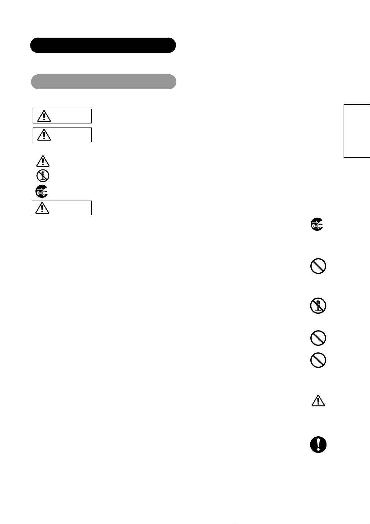
About the Symbols
Various symbols are used in t his m an u al , th e use r’s manual an d o n t he prod u ct i ts el f t o e nsu re co rrect us ag e, to prevent danger to the users and to prevent
property damage. T he me anings of these sy mb ols a re des cribed below. It is important that you read t hes e d escriptions tho roughl y and fully understand the
contents.
This symbol indicat es inf or mation tha t, if i gnored, could possibl y result in p erson al inju ry o r ev en de ath d ue to in correct
WARNING
CAUTION
Typical Symbols
This symbol indicates an additional warning (including cautions). An illustration is provided to clarify the contents.
handling.
This symbol indica tes information t hat, if ignored, could result possibly in p ersonal injury or physical damage du e to
incorrect handling.
This symbol indicates a prohibited action. The contents will be clearly indicated in an illustration or adjacent to the symbol (t he sym bol to the l eft
indicates that disassembly is prohibited).
This symbol indicates a compulsory ac tion. The conte nts will be clearly in dica ted in an illust ration or a djacent to the sym bol. (Th e s y mb ol to the
left indicates that the power plug should be disconnected from the power outlet).
ENGLISH
WARNING
Never use the monitor if a problem should occur.
Abnormal operations such as smoke, strange odor, no image, no sound, excessive sound, damaged casing, elements, cables,
penetration of liq uids or foreign matter, etc. can cause a fire or electrical shock . In s uch ca se, immediately tur n off the power switch and
then disconnect the power plug from the power outlet. After making sure that the smoke or odor has stopped, contact your dealer. Never
attempt to make repairs yourself because this could be dangerous.
Do not insert liquids or foreign objects.
Penetration of l iquids or f oreign objects coul d result in fire o r electrical sh ock. Use spe cial caution in households where children are
present.
If liquids or foreign obj ects sho uld enter th e project or, immediately tur n off the po wer s witc h, disco nnect t he power plug from t he pow er
outlet and contact your dealer.
• Do not place the monitor in a bathroom.
• Do not expose the monitor to rain or moisture.
• Do not place flower vases, pots, cups, cosmetics, liquids such as water, etc on or around the monitor.
• Do not pla ce met al s, co m busti bl e s, etc on or around the moni t or.
Never disassemble or modify the monitor.
The monitor contains high voltage components. Modification could result in fire or electrical shock.
• Never remove any fixed cover.
Do not give the monitor any shock or impact.
If the monitor should be shocked and/or broken, it could result in an injury, and continued use could result in fire or electrical shock. If the
glass panel is broke n or d am ag e d, immediately turn off the p owe r switch, disco nne ct the power plu g from the power ou tlet and contact
your dealer.
Do not place the monitor on an unstable surface.
If the monitor should be dropped and/or broken, it could result in an injury, and continued use could result in fire or electrical shock.
• Do not place the monitor on an unstable, slant or vibrant surface such as a wobbly or inclined stand.
Do not obstruct the ventilation of the monitor.
If the ventilation is ob structed during the o peration of the monito r or just after switching off the pow er, it could result in damage and
shorten the lifespan of your monitor due to overheating. Make sure there is ample ventilation.
• Keep a space of 100mm (10cm) or more between the sides, rear and top of the monitor and other objects such as walls.
• Do not place anything around ventilation openings of the monitor.
• Never block ventilation openings.
• Do not put the plas ma scree n side up .
• Do not cover the monitor with a tablecloth, etc.
• Do not place the monitor on a carpet or bedding, or near a curtain.
Use only the correct power outlet.
Incorrect power supply could result in fire or electrical shock. Use only the correct power outlet depending on the
indication on the monitor and the safety standard.
• The enclosed power cord must be used depending on the power outlet to be used.
plug from the
power outlet.
Do not
Disconnect the
Disassemble.
6
Page 7
g
WARNING
Be cautious of the power cord connection.
Incorrect connection of the power cord could result in fire or electrical shock.
• Do not touch the power cord with a wet hand.
• Check that the connecting portion of the power cord is clean (with no dust), before using. Use a soft and dry cloth to clean the power
plug.
• Insert the power plug into a power outlet firmly. Avoid using a loose, unsound outlet or contact failure.
• Do not cut off the fitted power plug, the removal of which could lead to impaired performance. If you wish to extend the lead, obtain an
appropriate extension lead or consult your dealer.
• Should you require replacing the fuse in the molded plug with a new fuse, then please replace with new one of the same value, type and
approval as the original. Ensure the fuse cover is returned to its original position.
Be sure to keep safety ground connection.
Connect the gro und t ermin al o f AC inl et of t his mo nit or wi th th e gr ound termi nal provi ded at the powe r outl et using the encl ose d pow er
cord. If the provided plug does not fit your outlet, consult an electrician for replacement of the obsolete outlet.
Be careful in handling the power cord and external connection cables.
If you keep using a dama ged th e pow er c ord or cabl es, it c an cau se a fire o r electri cal sh ock. Do n ot a pply too much h eat, pres sure or
tension to the power cord and cables. If the power cord or cables are damaged (exposed or broken core wires, etc.), contact your dealer.
• Do not place the monitor or heavy objects on the power cord and cables. Also, do not place a spread, cover, etc, over them because this
could result in the inadverte nt pl aci ng of heavy objects on the concealed po wer cord or ca bles.
• Do not pull th e powe r cord an d cables . When c onne ctin
plug or connector.
• Do not place the cord near the heater.
• Do not touch the power plug just after disconnecting it from the power outlet to prevent electric shock.
• Do not touch the power plug when lightening is close to you.
• Avoid coiling the power cord and bending it sharply.
• Prote ct the power cord from bei ng walked o n, pinched p articularly a t plugs, conveni ences receptacles, a nd the point whe re they exit
from the apparatus.
• Do not modify the power cord.
and disconnecti ng the power cord or cabl es, d o it with y o ur han d holdi ng the
Be careful in handling the battery of the remote control.
Incorrect handling of the battery could result in fire or personal injury. The battery may explode if not handled properly.
• Keep the battery away from children and pets. If swallowed consult a physician immediately for emergency treatment.
• Do not allow the battery to be exposed to fire or water.
• Avoid fire or high-temperature environment.
• Do not hold the battery with metallic tweezers.
• Keep the battery in a dark, cool and dry place.
• Do not short circuit the battery.
• Do not recharge, disassemble or solder the battery.
• Do not physically impact the battery.
• Use only the battery specified in the manual of this monitor.
• Make sure the plus and minus terminals are correctly aligned when loading the battery.
• If you observe a leakage of the battery, wipe out the liquid and then replace the battery. If the liquid adheres your body or clothes, rinse
well with water.
• Obey the local laws on disposing the battery.
Surely connect
the ground wire.
ENGLISH
7
Page 8
SAFETY INSTRUCTIONS(continued)
CAUTION
Be careful in moving the monitor.
Neglect could result in an injury or damage.
• Do not move the monitor during use. Before moving, disconnect the power plug and all external connections.
• You are advised to move the monitor with two persons.
• Avoid any impact or shock to the monitor; particularly take care of glass screen.
Do not put anything on top of the monitor.
Placing anything on the monitor could result in loss of balance or falling, and cause an injury or damage. Use special caution in
households where children are present.
Avoid a humid or dusty place.
Placing the monitor in a smoke, a highly humid, dusty place, oily soot or corrosive gas could result in fire or electrical shock.
• Do not place near the kitchen, a humidifier or other place where there is oil, smoke or humidity.
Avoid a high temperature environment.
The heat could have advers e in flu enc e on the moni t or an d oth er pa r t s, and co uld res ult in trans formation, melting or fi re.
• Do not place the monitor, the remote control and other parts in direct sunlight or near a hot object such as heater, etc.
• Do not put the monitor in a place where the temperature is widely changing.
Remove the power cord for complete separation.
• For safety pu r poses, disconnect the power cord if the moni to r is not to be use d for prol on g ed pe rio ds of time .
• Before cleaning, turn off and unplug the monitor. Neglect could result in fire or electrical shock.
Disconnect the
plug from the
power outlet.
Never remove the back cover of the monitor as this can expose you to very high voltages and other
hazards
• If the monitor does not operate properly, unplug the monitor and call your authorized dealer or service center.
Prevention of screen burn in
• Conti nu ous on -sc reen displays such as video games, stock mark et qu otati on s , com put er g ene rat e d gra phi cs, an d oth er fi xe d (no n- moving) patterns can
cause permanent damage to the monitor. Such “SCREEN BURN IN” constitute misuse and are NOT COVERED by our Factory Warranty.
These servicing instructions are for use by qualified service personnel only
• To reduce the risk of electric shock, do not perform any servicing other than that contained in the operating instructions unless you are qualified to do so.
Do not place any objects on top of the monitor
• They may fall or cause a child to climb up to retrieve the objects.
ENGLISH
PRECAUTIONS
Installation environment
Do not obstruct a ventilation hole.
Do not put the monitor on carpet or blanket, or near a curtain which has a possibility of obstructing a ventilation hole of the monitor.
Do not put the monitor in the following places.
• Hot places such as near heater, place exposed to the direct rays of the sun.
• A place where the temperature is widely changing.
• Places with soot, dust or high humidity.
• Poor air ventilation place.
• Place near fire.
• A wet plac e such as bathroom, or shower room.
• Place where you can trip over it.
• Always vibrating or strongly vibrating places.
• Distorted or unstable p laces.
How to view the monitor
If you use the monitor in too dark a room, your eyes may become tired.
Please use it in a reasonably bright room.
Avoid direct rays of the sun to the screen in order to prevent eye fatigue.
Yo ur eyes will get fatigued after viewing the monitor for long period of time.
Relax your eyes by viewing away from the monitor from time to time.
Please watch the monitor in downward direction.
Note on image retention
The Plasma display illuminates phosphor to display images. The phosphor has a finite illumination life. After extended periods of illumination, the brightness
of the phosphor will be degraded to such extent that stationary images would burn-in that part of the screen as grayed-out images.
Please refer to the user manual for this model for instruction on how to use these features.
• Ensure screen saver mode is activated.
• Always display the image in a mode that fills the screen.
• Avoid using split screen mode for long periods of time.
• Do not allow the “On Screen Display” to stay on for long periods of time.
• Do not display still images, such as menus from game consoles, T/Text, PCs or logos, on the panel for long periods of time.
• We recommend that the “Contrast” and “Brightness” level is reduced as much possible.
How to clean the plasma screen panel of the monitor
Before cleaning the monitor, turn off the monitor and disconnect the power plug from the power outlet.
To prevent scratching o r da magi ng the plas ma scree n face , do n ot k nock o r rub t he sur fa ce wit h shar p or h ard obj ects. C lea n the screen wi th a soft cl oth
moistened with warm water and dry with a soft cloth. If it is not enough, then use a cloth with mild detergent. Do not use harsh or abrasive cleaners.
8
Page 9

How to clean the cabinet of the monitor
Use a soft cloth to clean the cabinet and control panel of the monitor. When excessively soiled dilute a neutral detergent in water, wet and wring out the soft
cloth and afterward wipe with a dr y soft cloth.
Never use acid/alkali ne deter gent, alcoholi c detergent , abrasive clea ner, powder soap, OA clean er, car wax, glass cleaner, etc. especially be cause they
would cause discoloration, scratches or cracks.
Prevention of an obstacle to Radio receivers
This monitor has been desig ne d purs u ant to the international EMI stan d ards. This is to prevent a probl em to R adi o receiv er s.
• Keep the monitor away from Radio.
• Adjust Radio antennas in order for the monitor not to receive interference.
• The antenna cable of Radio should be kept away from the monitor.
You can check if this monitor influences Radio receivers by turning off all other equipment other than the monitor.
If you find a problem receiving Radio when using the monitor, check the instructions mentioned above.
Precautions for the cable connection
• Do ensure that all connections, (including the power plug, extension leads and interconnections between the pieces of equipment), are
properly made and in accordance with the manufacturers instructions. Switch off and withdraw the power plug before making or
changing connections.
• Confirm the connector is fixed tightly when the signal cable is connected.
Also confirm the screws on the connector are tightened.
• Plug the power cord of the monitor into a different socket from that for other equipment, such as Radio etc.
• Use a plug with ground terminal and make sure that it connects to the ground.
Precaution during transportation
Please pay attention when you transport this monitor because it is heavy.
Furthermore, use the original carton box and its packaging materials when the monitor is transported.
Failure to transport the monitor in any carton except the original carton may result in damage to the monitor.
Save the original carton box and all packing material.
Do not physically impact the remote control.
• A physical impact could cause damage or malfunction of the remote control.
• Take care not to drop the remote control.
• Do not place heavy objects on the remote control.
Avoid strong rays.
Any strong rays (such as direct sun rays or room lighting) onto the remote control sensors could invalidate the remote control.
Avoid radio interference.
Any interfering radiation could cause distorted images or noises.
• Avoid radio generator such as a mobile telephone, transceiver, etc. around the monitor.
Set the sound volume at a suitable level.
It is better to keep the volume level low and close the windows at night to protect the neighborhood environment.
Precautions for the installation
• Do not use makeshift stands and NEVER fix legs with wood screws - to ensure complete safety, always fit the manufacturers approved
stand or legs with the fixings provided according to the instructions.
• Use only with the cart, stand, tripod, bracket, or table specified by the manufacturer, or sold with the apparatus. When a cart is used, use
caution when moving the cart/apparatus combination to avoid injury from tip-over.
• This product is designed to comply with the recommended safety standards for tilt and stability. Do not apply excessive pulling force to
the front, or top, of the cabinet that could cause the product to overturn resulting in product damage and/or personal injury.
• Follow instructions for wall, shelf or ceiling mounting as recommended by the manufacturer.
• Only use the attachments/accessories specified by the manufacturer.
• Consult your dealer if you are in any doubt about installation, operation or safety of your equipment.
Other precautions
• Do not leave equipment switched on when it is unattended unless it is specifically stated that it is designed for unattended operation or
has a stand-by mode. Switch off using the switch on the equipment and show your family how to do this. Make special arrangements for
infirm or handicapped people.
• Disposal of this product may require specific instructions pertaining to your resident region.
• Never guess or take any chances with electrical equipment of any kind - it is better to be safe than sorry!
ENGLISH
9
Page 10
INSTALLATION INSTRUCTIONS
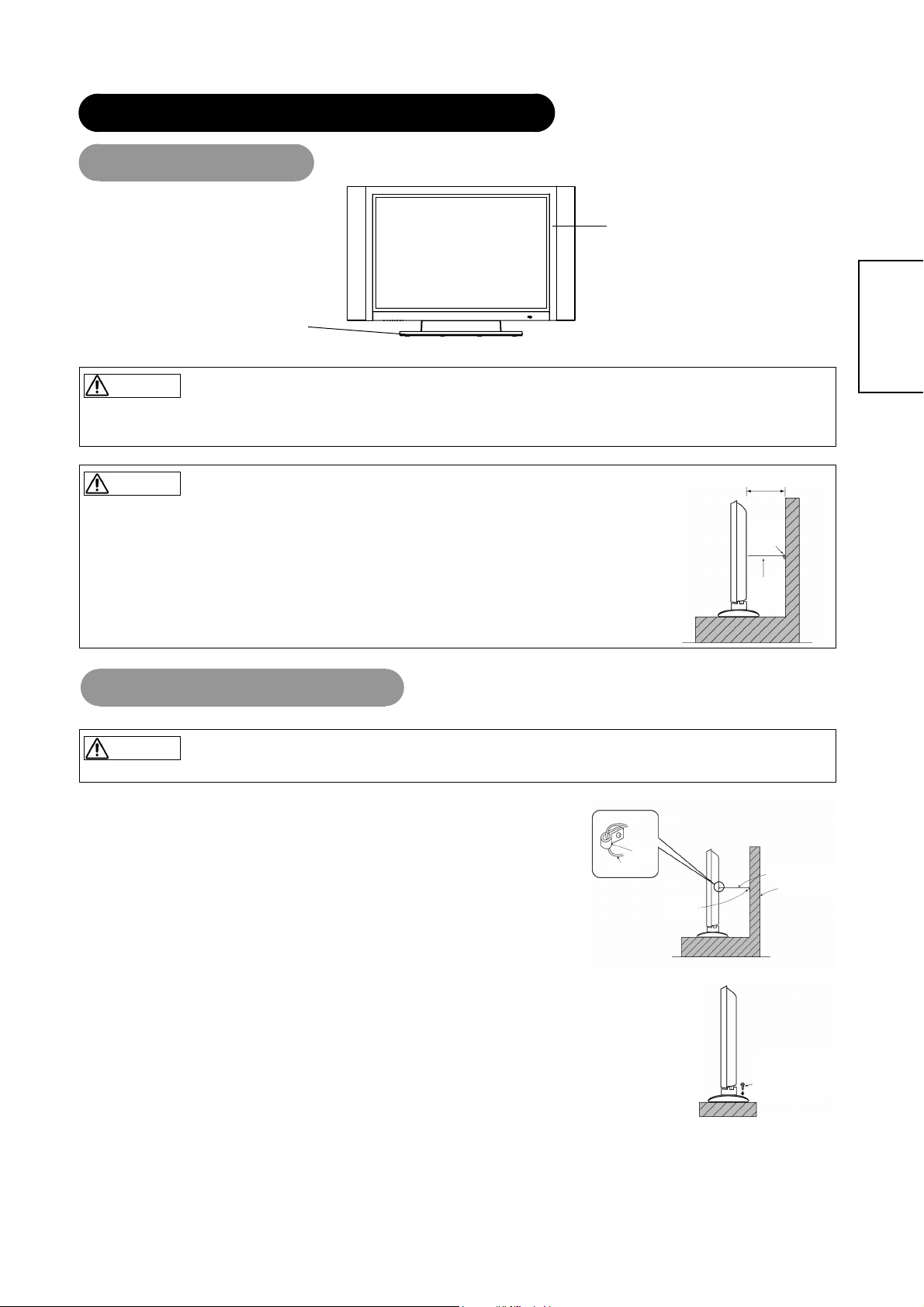
Installation
Display
Desk top stand
WARNING
Use one of the spe cial mount uni ts to install this product. A mount of insufficient s trength or ina dequate desi gn can cause overturning or dropping and
result in fire, electrical shock or injury. Please note that our company assumes absolutely no responsibility for personal injuries or property damage caused
by use of other mount units or improper installation.
CAUTION
• Installation of the wall mount unit and ceiling mount unit can be dangerous, so do not attempt this yourself. Ask your
10cm (4 inches) or more*
dealer to provide the name of a qualified installer.
• In order to prevent an internal temperature increase, maintain a space of 10cm (4 inches: For a desktop set- up) or
more between the sides and other objects such as walls, etc., so that the ventilation holes are not blocked. (*)
Clamp
Cord
or
chain
Anti-tumble measures
CAUTION
Have this unit mounted in a stable place. Take measures to prevent it from tumbling down to avoid possible physical injury.
Securing to a wall or pillar
Using a commercially available cord, chain and clamp, secure the set to a firm wall or pillar.
ENGLISH
Securing desktop
1) Using wood screws (two) fasten the set to the clamping screw holes on the rear of the stand as shown.
2) Using commercially available wood screws, secure the set firmly in position.
10
Chain
Hook
Clamp
cord or chain
Wall or Pillar
Mounting Screw
hole location
Wood
Two places
Page 11
INSTALLATION INST RU CT IONS (continued)
Mounting the speaker
Refer to the instruction manual concerning mounting of the optional speaker unit.
SPEAKER
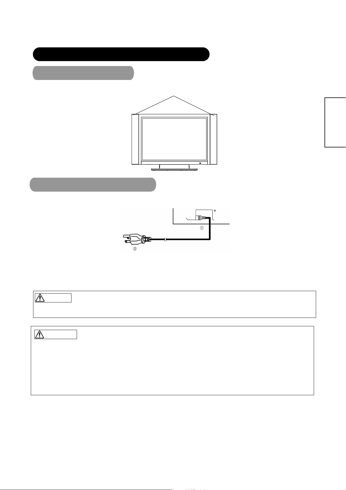
Power Cord Connection
Connect the power cord, after completing all other connections.
ENGLISH
c Connect the power cord to this device.
d Connect the power cord plug to the power outlet.
(The type of plug is different from this drawing for some countries.)
CAUTION
• Use only the power cord provided.
• Do not use a power supply voltage other than that indicated (AC100-240V, 50/60Hz) as this may cause fire or electric shock.
WARNING
Be cautious of the power cord connection.
Incorrect connection of the power cord could result in fire or electrical shock.
• Do not touch the power cord with a wet hand.
• Check that the connecting portion of the power cord is clean (with no dust), before using. Use a soft and dry cloth to clean the power plug.
• Insert the power plug into a power outlet firmly. Avoid using a loose, unsound outlet or contact failure.
• Do not cut off th e fitted pow er plug, the removal of w hich coul d lead to i mpaired per forma nce. If y ou wish to extend the l ead, obtain anappropriate
extension lead or consult your dealer.
• Should you require replacing the fuse in the molded plug with a new fuse, then please replace with new one of the same value, type and ap proval as
the original. Ensure the fuse cover is returned to its original position.
11
Page 12
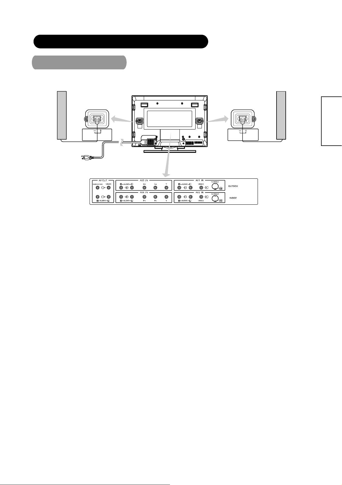
INSTALLATION INST RU CT IONS (continued)
Connecting Signal
Make sure that the power switch of the Display is turned off.
Speaker(R)
Speaker Terminal
(6Ω) 10 W
Display rear panel
Speaker Terminal
(6Ω) 10 W
Speaker(L)
ENGLISH
12
Page 13
play
INSTALLATION INST RU CT IONS (continued)
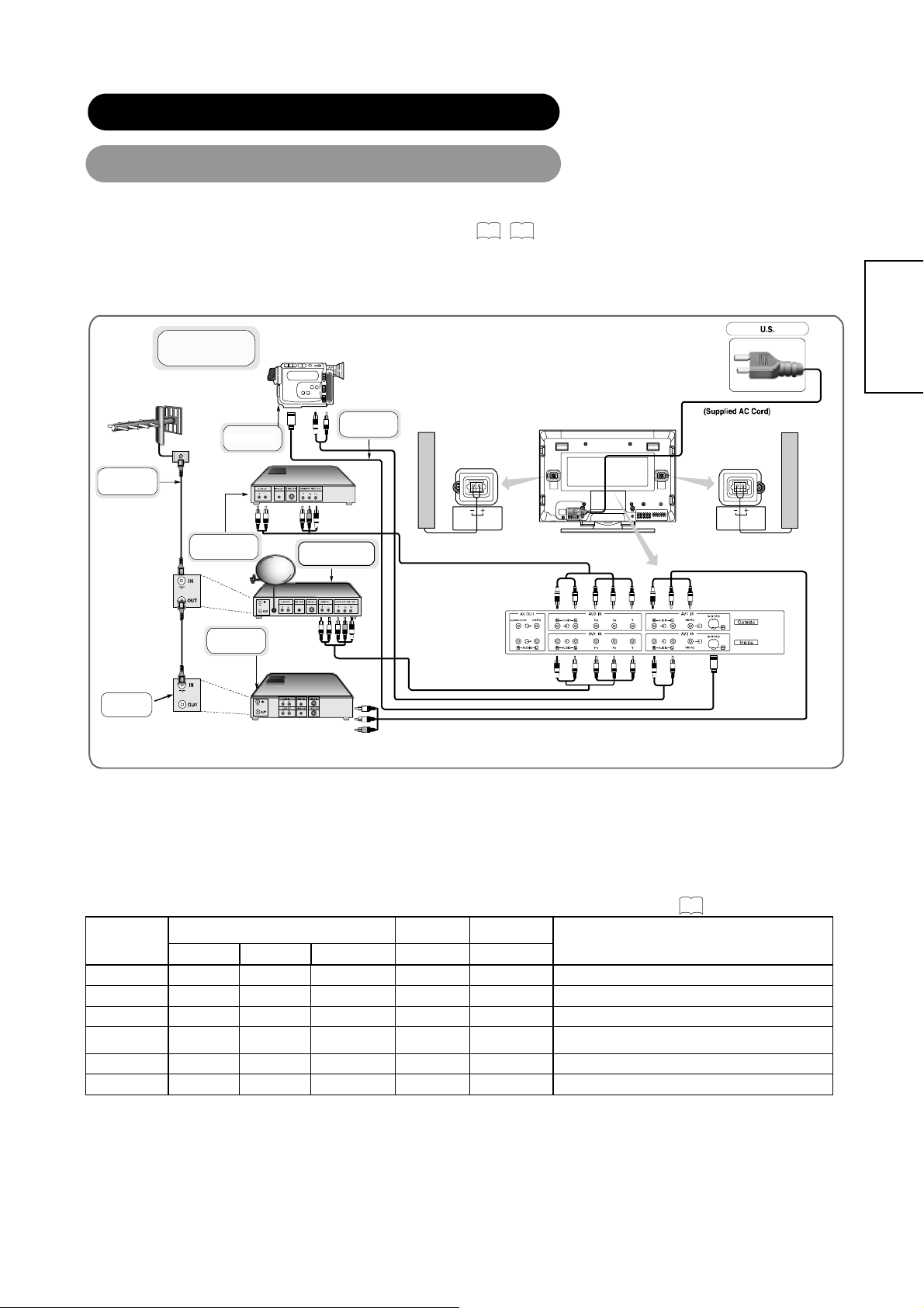
Connecting to Video Imaging Device
(1) Make sure that the di splay signal of the personal computer to be used is compatible wi th the specifications of this
device.
45
• See "Product Specifications" concerning the specifications of this device. 42~
(2) Make sure that the power switch of the monitor is turned off.
(3) Make sure that the power switch of the imaging device is turned off.
(4) Use a commercially available cable and connector to connect the signal input terminal on the rear panel of this device and
the signal output terminal of the imaging device.
AERIEL
Display Quick Connection
CAMCORDER
DVD PLAYER
Cable/ Satellite Decoder
Box
*Cable shown are not supplied with the monitor and are available locally
where ever consumer electronic product are sold.
S-CABLE
Speaker(R)
SPEAKER TERMINAL
(6Ω) 10W
Best Connection
Monitor rear panel
Power Code
Speaker(L)
SPEAKER TERMINAL
(6Ω) 10W
Basic Connection
ENGLISH
VCR
ANTENNA/
CABLE
SIGNAL
*You can connect regular DVD
er to AV4 IN as well
Better
Connection
[An example of connecting video components]
z If the OUTPUT (MONITOR) terminal is connected to a 2nd monitor, it is possible to view the same image as on the main source. The composite
video signal from AV1, AV2 input will be displayed on both screens at the same time.
z If video equipment with an S vedio output terminal is used, cabling by the S vedio cable is recommended to provide finer vedio quality. (If an S
vedio input terminal and a vedio input terminal of AV3 connect to the monitor at the same time, S vedio input would govern.)
Applicable video signals for each input terminal
Terminal
RCA D-sub DVI
(See PRODUCT SP EC I FIC ATIONS for detai ls ,
Composite S-video Component RGB 1 RGB 2
AV1 ○ ○
AV2 ○ ○
AV3 ○ 480i, 567i Video Signal only
AV4 ○
480i, 576i, 480p, 576p, 720p/50, 720p/60, 1080i/50,
1080i/60, inputs Video Signal
RGB1 ○
RGB2 ○
(O: Available)
42
)
Remarks
13
Page 14
N
N
T
INSTALLATION INST RU CT IONS (continued)
6
9
Read SAFETY INSTRUCTIONS (
)
to
carefully to ensure maximum safety before proceeding
to these steps:
• Choose an appropriate site and install the product on a level table where the stand is secure.
• Install the monitor to have ready access to a power socket available.
• Make sure that the power switch of this device is turned off.
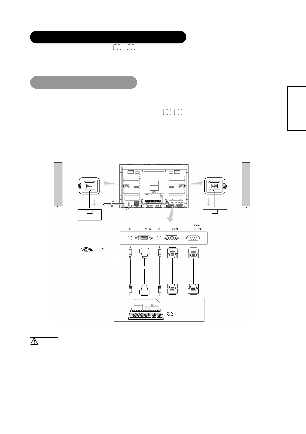
Connecting to a PC
Con
(1) Make sure that t he display signal of the personal computer to be used is compatible with the specificati ons of this
device.
45
• See "Product Specifications" concerning the specifications of this device. 42~
(2) Make su re that the power switch of the personal com puter is turned off.
(3) Connect the signal input terminal (RGB 1 or RGB 2) on t he rear panel of this device to the Monit or signal output
terminal of the personal computer.
• Use a cable that fits the input terminal of this device and the output terminal of the personal computer.
• Depending on the type of personal comp ute r being connected, the use of an opti on al conv er si on ada pte r or the ad apt er provided with the
personal computer may be nec essa r y in some cases. For det ai ls, refer to the instr uction manual of the personal co m put er or ask the personal
computer manufacturer or your local retail dealer.
Monitorrear panel
Speaker(R)
Speaker (L)
ENGLISH
SPEAKER TERMINAL
(6Ω )10W
Power
Cord
Power Cable
Connector
3.5mm
Stereo
Audio Cable
To Audio
Output
AUDIO I
RGB 2
DIGITALINPU
RGB 2
DVI-D
Connector
AUDIO I
RGB 1
ANALOG INPUT
RGB 1
15Pin D-Sub
VGA Connector
T o Video
Output
SPEAKER TERMINAL
(6Ω )10W
9-Pin D-Sub
RS-232C connector
To PC 9-Pin
To PC 9-Pin
RS-232C connector
RS-232C connector
PC
•
Note
Please refer to the caution regarding prevention of screen burn in on page 3.
Subwoofer Output provides a single un-amplified audio output that passes along the audio signal from the Plasma Display.
Note: When using a Home Theater audio system with this Plasma Display, please connect the sub woofer (if originally supplied with the audio
system) directly to the Home Theater components subwoofer terminal.
14
Page 15

COMPONENT NAMES
NOMS DES COMPOSANTS
Main Unit
Panel
Control panel
• Adjustment buttons are located
on the bottom.
• The back cover is provided with
indications to distinguish the
adjustment buttons.
MENU button
SOURCE button
Front
ENGLISH
Remote-control
16
20
• The main power switch is located at the back, on the lower
19
surface.
Main power switch (See page
Power lamp
receiver
18
18
)
ENTER button
VOLUME UP/DOWN buttons
( ADJUST buttons)
SUB-POWER button (See page
• ( ) indicates the function while the MENU is displayed on the screen.
20
18
)
PROGRAM UP/DOWN
buttons
( SELECT button.)
Caution when moving the main unit
• As this product is heavy, whenever it is moved, two
people are required to transport it safely.
• Whenever the unit is moved it should be lifted forwards
using the two handgrips at the back, and the unit s hould
then be held at the base on both sides for stability.
Handgrips
Handgrips
External
Speaker
Terminals
19
Rear
14
Handgrips
External
Speaker
Terminals
14
RGB input terminal
15
Page 16

g
0
8
6
0
6
3
3
3
COMPONENT NAMES(continued)
Remote Control
l
POWER O N/OFF button
SLEEP button
ASPECT button
PIP bu tton
STILL button
VOLUME U P /DO WN buttons
MENU button
ENTER button
DISPLAY button
1
6
35
28
3
19
20
2
2
19
SOURCE button
6
ZOOM button
3
SWA P butto n
19
MUT E button
2
SELECT/ADJUST button
ENGLISH
AV2 button
AV1 button
RGB1 button
19
19
19
19
19
19
AV3 b utton
AV4 b utton
RGB2 button
1. Open the battery cover.
Loading Batteries
Slide back and remove the ba ttery
cover in the direction of the arrow.
Handing the Remote Control
Handling the Remote Control
Use the remote control within about 5m from the front of the unit’s
remote-control sensor and within 30 degrees on both sides.
2. Load batteries.
Load two Size AAA batteries included observing the Polarities.
With in 30
degrees
About 10
feet
About 16 feet
3. Close the battery cover.
• Replace the battery cover in the direction of the arrow and snap it
back into place.
With in 30
rees
de
About 10 feet
CAUTION
z Do not use new an d old batteries together. The batteries could explo d e
or leak, resulting in fires, physical injury, or stains.
z When loading batteries, observe their correct polarities as marked on
the product. If loaded in the wrong direction, the batteries could
explode or leak, resulting in fires, physical injury, or stains.
16
ATTENTION
z Do not drop or im pa ct the re mot e con tr ol ..
z Do not splash the remote control with water or put it on a wet object.
z Before l eaving the remote contr ol out of use for an extended pe riod of
time, remove the batteries from it.
z If the remote control begins to lack responsiveness, replace the
batteries.
z Strong light, such as direct sunlight, shining on the photoreceptor of
the remote control can cause operational failure.Position this unit to
avoid direct contact with such light.
Page 17

P
COMPONENT NAMES(continued)
Remote Control (continued)
POWER
Press this button to turn the TV on or off.
TV(Optional)
Press this button to choose TV as the
source.
SOURCE
Press this button to select the INPUT
Source.
SLEEP
Press this button to activate the Sleep
Timer menu.
S. MODE
Creates a surround sound effect.
ASPECT
Press this button to select how the
picture is displayed on the screen;
4:3,16:9, Panoramic, or Cinema modes.
PIP
Press this button to show the PIP and
change the size of PIP.
VOL
Press these two buttons to a djust th e
volume up or down.
MENU
Press this button to select the On Screen
Display Men u .
DISPLAY
Press this button to show the i nput
signal informat io n.
ZOOM
Press this button to change the picture
size.
MULTI P
Use the/ buttons to select the
PIP setting.
SWA
Press this button to excha nge main
picture with PIP picture.
STILL
Press this button to freeze the picture.
Press it again to return to normal
operation.
CH
Press these two buttons to sel ect the
channel up or down.
LAST CH
Press this button to return to the last
Channel viewed.
MUTE
Press this button to turn off the sound.
Press it once more or press thevolume
up button to return the soun d.
ENGLISH
AV2
Press this button to select the VIDEO 2
or S-VIDEO 2 INPUT.
AV1
Press this button to select the VIDEO 1
or S-VIDEO 1 INPUT.
RGB1
Press this button to select the RGB1
VGA INPUT.
RGB2
Press this button to select the RGB2
DVI-D INPUT.
MTS(Optional)
Press this button to select Multi-channel
television sound. This but t on operates
only in the TV mode.
NUMBERS KEYPAD(Optional)
Press these buttons to acce ss t he
corresponding TV chan nels.
AV3
Press this button to select the AV3 480i
INPUT.
AV4
Press this button to select t he AV4
480p/480i INPUT.
17
Page 18

OPERATING INSTRUCTIONS
Power lamp
Main power switch
SUB-POWER button
POWER ON/OFF
button
Turing Power On and Off
To turn the monitor power ON, press the main power switch on the
monitor main unit to ON, and then press the SUB POWER button or
the ON/OFF or ON button on the remote control.
To turn the monitor power OFF, press the SUB POWER button or
the ON/OFF or OFF button on the remote control, and then press the
main power switch on the monitor main unit to OFF.
z During normal use, the main power switch is set in the ON position, and
the monitor can then be turned ON/OFF using the SUB POWER button or
the ON/OFF button on the remote control.
Indicating lamp
Indicating
lamp
Off Off
Lights red
Lights green On
Lights orange
When the indicating lamp lights in orange or the message “No cable
connected” and “Going to sleep” appears on the screen, there is
something unusual a bout the st atus of recep tion. See “Power Save Mode”
(In RGB1 or RGB 2 mode) or “Symptoms That Seemingly Appear to be
Failures.”
39 40
ATTENTION
• Avoid repeatedly t ur ning t he monit or o n an d off at sh ort time int ervals .
Failures might result from such oper ation.
• Turn off the main power switch before leaving the monitor out of use for
an extended period of time.
If a power failure occurs while the main unit is running, it would be
powered on upon recovery from the failure. Turn off the unit main power
switch before leaving the main unit.
Power status Operating
When the main pow er switch is set
to OFF.
When the main power sw itch is ON ,
Off
(standby)
Off
(Power Save)
and the OFF button on the remot e
control or the SUB POWER button
on the undersi de of the front of the
frame is OFF.
When the main power sw itch is ON ,
and the ON button on the remote
control or the SUB POWER button
on the undersi de of the front of the
frame is ON.
When the main power sw itch is ON ,
and the ON button on the remote
control or the SUB POWER button
on the undersi de of the front of the
frame is ON.
However, the state in POWER
SAVE mode.
ENGLISH
18
Page 19

OPERA T ING INSTRUCTIONS (continued)
VOLUME UP/DOWN
buttons
VOLUME
CONTROL
Select
SOURCE button
TV(Optional)
SOURCE
MUTE
V olume Adjustment
The volume can be adjusted by pressing the VOLand
VOL buttons of the remote control (or the and volume
buttons of the monitor unit).
Adjustment status guide display
z When a button is pressed, the volume adjustment status
guide will be displayed.
• The volume will increase when the VOL button is pressed while the
guide is being displayed.
• The volume will decrease when the VOL button is pressed while the
guide is being displayed.
Audio Mute
The audio volume can be temporarily muted by pressing the
MUTE button of the remote control.
Volume setting value
15
ENGLISH
AV1,AV2,AV3
RGB1,RGB2,AV4
buttons
Input Switching
- Input can be switched by pressing t he AV1, AV2, AV3, AV4, RGB1, or
RGB2 buttons.
- Input can be switched in the sequence AV1-Video ÆAV1-Svideo Æ
AV2-Video Æ AV2-SVideo Æ AV3 YCbCr Æ AV4 YPbPr/YCbCr Æ
RGB1 VGAÆ RGB2 DVI-D by pressing the SOURCE button and then
select the Input with the select keysand then press th e EN TE R
button.
AV1
RGB2
AV1S
RGB1
AV2
AV4
AV2S
AV3
z When the MUTE bu tton is pressed, the above icon will
appear.
• The volume setting can be lowered by pressing the VOL button while
the audio is muted.
• Muting can be cancelled by pressing the VOL button or the MUTE
button while the audio is muted.
19
Page 20

OPERATING INSTRUCTI ONS (continued)
MENU button
PROGRAM/
ADJUST
buttons
ENTER button
SELECT buttons
Using the Menu Screen
(On-screen display system)
When the MENU button is pressed, the adjustment menu
screen will appear. Adjustment and setting are possible by
using the SELECT buttons, PROGRAM ADJUST buttons and
the ENTER button.
17
_
concerning the adjustment items and the settings.
32
Refer to
Example: Selecting the picture screen
1. Press the MENU button to display the Main Menu screen.
2. Select the Picture Parameters screen with theand
PROGRAM ADJUST buttons and press the
ENTER button.
ENGLISH
3. Use theand SELECT buttons to select the item to be
adjusted and then use the
Brightness.)
and to adjust (example:
• Press the MENU button to return to the previous screen.
• If there is no operation for a period of one minute, the
Adjustment Menu screen will disappear.
20
Page 21

OPERATING INSTRUCT IONS (contin ued)
Selected
characters
PICTURE
PARAMETERS
CONTRAST AUTO BASS PIP POSITION OSD POSITION
BRIGHTNESS CLOCK TREBLE PIP SIZE OSD TIMEOUT
COLOR PHASE BALANCE MULTI PIP OSD LANGUAGE
TINT POSITION SURROUND SLEEP TIMER
COLOR TEMP I/P INFO
SHARPNESS FACTORY RESET
BLACK ENHANCE SCREEN SAVER
POWER SAVE SCREEN WIPE
GAMMA STANDBY WHITE
PICTURE NR INVERSE
PC PARAMETERS AUDIO SETTINGS PICTURE IN
ENGLISH
PICTURE
GENERAL
SETTINGS
21
Page 22

PICTURE PARAMETERS
ENGLISH
*Press "MENU" button to return to Main Menu, then press “MENU” button to exit OSD.
Selected characters
CONTRAST
BRIGHTNESS
COLOR
TINT
Narrows the gap between light and
dark.
Black is increased for overall darkness. Black is decreased for overall brightness. Adjust as desired.
Decrease color level. Increase color level. Adjust as desired.
Enhances red and weakens green. Enhances green and weakens red. This can be adjusted when receiving the signal
Broadens the gap between light and dark. Adjust for imum visibility to suit the ambient
22
Setup hint
brightness.
and will be greyed out.
Adjust as desired for photo realistic skin color.
Page 23

PICTURE PARAMETERS (continued)
ENGLISH
*Press "MENU" button to return to Main Menu, then press “MENU” button to exit OSD.
Selected characters
COLOR TEMP
COOL
NORMAL
WARM
USER R
USER G
USER B
Adjust color temperature depending on the user’s preference.
These settings are independently stored in each of the 3 Color
Temperature
23
Setup hint
Page 24

PICTURE PARAMETERS (continued)
ENGLISH
*Press "MENU" button to return to Main Menu, then press “MENU” button to exit OSD.
Selected characters
SHARPNESS
BLACK ENHANCE
Softens picture Sharpness picture
LOW
MIDDLE
HIGH
OFF
Adjust sharpness of picture depending on the user’s preference.
Normally set to LOW. Adjusts the black level compensation.
NOTE
The noise appears on the screen according to the content of the picture when this is set in the direction of Sharp.
In that case, it is possible to improve it by this setting to the Soft side.
24
Setup hint
Page 25

PICTURE PARAMETERS (continued)
ENGLISH
*Press "MENU" button to return to Main Menu, then press “MENU” button to exit OSD.
Selected characters
POWER SAVE
GAMMA
PICTURE NR
OFF
2.2
LOW
HIGH
2.8
ON
OFF
Normally set to OFF.
By this control, power consumption can be reduced or degradation of a panel can
be mitigated. The order of power consumption is HIGH < LOW < OFF..
Normally set to 2.2.
Normally set to ON
If this is set to ON, it helps to reduce the noise interference visible on the screen.
25
Setup hint
Page 26

OPERATING INSTRU CTIONS (contin ued)
P
PC PARAMETERS
ENGLISH
*Press "MENU" button to return to Main Menu, then press “MENU” button to exit OSD.
Selected characters
AUTO
CLOCK
PHASE
POSITION
Press the ENTER button to make the word “ON” light on.
Reduces the dot clock. Increases the dot clock.
Slows the dot clock. Phase. Advances the dot clock Phase.
Press the ADJUST button to adjust the display position. Adjust the horizontal and vertical display positions.
NOTE
PC PARAMETERS all function could be selected in RGB1 and only position setting active in AV4.
26
Setup hint
Normally set to off mode. Adjust automatically for clock, phase
and position.
Adjust for maximum character clarity.
Adjust for clear character visibility.
Page 27

AUDIO SETTINGS
ENGLISH
*Press "MENU" button to return to Main Menu, then press “MENU” button to exit OSD.
Selected characters
BASS
TREBLE
BALANCE
SURROUND
Suppresses bass. Enhances bass. Adjust to taste.
Suppresses treble. Enhances treble. Adjust to taste.
Suppresses right-side sound. Suppresses left-side sound. Adjust to taste.
OFF BASIC ENHANCE
Creates a surround sound effect.
Setup hint
27
Page 28

OPERATING INSTRUCTIO NS (continued)
PICTURE IN PICTURE (PIP)
Selecting PIP siz e
When the PIP button on the remote control is pressed, a black box will appear on
the screen.
Each time the PIP button is pressed, the size of box changes as follows.
OFF
SMALL MEDIUM LARGE SPLIT
PIP
SOURCE
ENGLISH
SELECTand
PIP-OFF
SMALL MEDIUM LARGE SPLIT
Selecting PIP So urce
While a black box appea rs on the sc reen, press SOUR CE button and PIP SO UR C E men u ap pe ars.
Picture mode will change in the following sequence, each time the remote button is pressed.
Select the SOURCE by using the select keys on the remote control. Then, press the
ENTER button
PIP Combinatio n Table
Available signals are limited in PIP mode as shown in the table below.
Main Source
AV1
AV2
AV3
AV4
RGB1
RGB2
Sub Source
AV1 AV2 AV3 AV4 RGB 1 RGB2
X ○ ○ ○ ○ ○
○ X ○ ○ ○ ○
○ ○ X ○ ○ ○
○ ○ ○ X X ○
○ ○ ○ X X ○
○ ○ ○ ○ ○ X
28
Page 29

OPERATING INSTRUCTIO NS (continued)
PICTURE IN PICTURE(PIP) (continued)
ENGLISH
*Press "MENU" button to return to Main Menu, then press “MENU” button to exit OSD.
Selected characters
PIP POSITION
PIP SIZE
Use the buttons to adjust pictures to the up or down positions.
Use the
buttons to adjust pictures to the right or left positions.
OFF SMALL MEDIUM LARGE SPLIT
Change PIP display position.
Change PIP display Size.
Setup hint
29
Page 30

PICTURE IN PICTURE(PIP) (continued)
ENGLISH
*Press "MENU" button to return to Main Menu, then press “MENU” button to exit OSD.
Selected characters
MULTI PIP
OFF.
PIP(1+12)
PIP(1+8)
PIP(1+3)
Use the / buttons to select the PIP setting.
Setup hint
NOTE
z Even if the input of the horizontal/vertical synchronizing signal (or video signal) stops in the MULTI PICTURE display, the mode will not change to power
save mode.
z Please be careful since image retention will occur if display is left in a MULTI PICTURE display state for a long period of time.
z It is normal condition if the sub source is slightly dim while the PIP function is on.
30
Page 31

OPERATING INSTRUCTIO NS (continued)
GENERAL SETTINGS
ENGLISH
*Press "MENU" button to return to Main Menu, then press “MENU” button to exit OSD.
Selected
characters
OSD POSITION
OSD TIMEOUT
buttons to adjust the OSD to right or left position Adjusts the OSD horizontal position.
Use the
10 Sec.
20 Sec.
3 Sec.
Adjusts OSD display and on-screen time.
Setup hint
31
Page 32

GENERAL SETTING S (continued)
ENGLISH
*Press "MENU" button to return to Main Menu, then press “MENU” button to exit OSD.
Selected characters
OSD LANGUAGE
SLEEP TIMER
I/P INFO
To display information about the input signal
ENGLISH 繁體中文 簡體中文
OFF
30 Min.
60 Min.
120 Min.
.
32
Setup hint
Sets the language for the OSD.
Set the display off time for each mode.
Displays information about the input signal.
Page 33

GENERAL SETTING S (continued)
ENGLISH
*Press "MENU" button to return to Main Menu, then press “MENU” button to exit OSD.
Selected
characters
FACTORY RESET
SCREEN SAVER
ON OFF Resets all settings to FACTORY defaults.
OFF
5 Min.
15 Min.
30 Min.
This moves the picture around the screen in small amounts, at set intervals, to
reduce the panel image retention. This is where stationary objects such as screen
logos, leave a slight image visible after they should have disappeared.
Setup hint
33
Page 34

GENERAL SETTING S (continued)
ENGLISH
*Press "MENU" button to return to Main Menu, then press “MENU” button to exit OSD.
Selected
characters
SCREEN WIPE
ST ANDBY WHITE
INVERSE
ON 60 Min. This is used to reduce the panel image retention theat can occur with stationary pictures
ON 60 Min. This function can change each level of RGB signal invert to reduce the panel
OFF
30 Min.
60 Min.
by the white field signal. Select On (continuous operation) or 60 Min. (time limit operation)
and press the ENTER button. Press the MENU button on the remote control to return to
normal viewing.
This function is also provided against the image retention. If time is set for this it em, the
screen changes into the white pattern when the monitor enters po wer save mode, and it
will continue for the period of setting time.
image retention. When this function is required. Select on (continuous operation) or 60Min.
(time limit operation) and press the ENTER button. And press the Menu or Return button to
exit.
Setup hint
34
Page 35

Size Switching (ASPECT)
ASPECT
The ASPECT button will select how the video image appears on the monitor’s screen.
There are 4 selections.
16:9 Displays a wide screen image.
4:3 Displays a 4:3 square picture with letterbox bands.
PANORAMIC
CINEMA Magnifies the image to fill the screen with a picture.
Stretches the picture to fill the screen, while leaving
images in the center of the picture the same.
ASPECT
ENGLISH
CINEMA
PANORAMIC
Note:
• You can select 4:3 and 16:9 aspect functions in RGB1 VGA,
RGB 2 DVI and AV4 mode.
• The Aspect function has no active at AV4 1080i, 720p input signals.
When you want to Set the display size to Input signal Display screen Remarks
Play a 4:3 image faithfully in a 16:9
screen in the standard vertical size
and horizontally squeezed.
Play a 4:3 image in a 16:9 screen
faithfully.
Play a 4:3 image faithfully in a 16:9
screen with the height and witch of
the middle of the screen enlarged on
equal scales and with both sides
appearing somewhat enlarged.
Play a 21:9 Cinema size image in the
4:3 image expanded vertically on the
16:9 screen.
16:9
4:3
PANORAMIC
CINEMA
(Cinema)
(Squeeze)
(4:3 signal)
An image with an aspect ratio of 16:9
shrunk horizontally to 4:3 to display in a 4:3
screen.
Blanking occurs on both sides.
In some cases, some slight blanking may
remain at the top and bottom.
35
Page 36

OPERATING INSTRUCTIO NS (continued)
ZOOM
Each time the ZOOM button of the remote control i s pressed, the
Image on the screen will be enlarged. There are 10 selections,
Zoom 0(=Normal size) to Zoom 9.
DISPLAY
Press this button to show the input signal information.
STILL
Press this button to freeze the picture.
Press it again to return to normal operation.
SLEEP
Press this button to activate the SLEEP TIMER menu.
SLEEP
ZOOM
DISPLAY
ENGLISH
SWAP
STILL
SWAP
Press this button to exchange main picture with PIP picture.
OTHER FEATURES
Automatic Store
e
Approximately 1 sec. after adjustment is completed; the adjustments will be recorded as shown in the table below.
Menu Display Registration condition
CONTRAST
BRIGHTNESS
COLOR
TINT
COLOR TEMP
SHARPNESS
BLACK ENHANCE
POWER SAVE
GAMMA
PICTURE NR
BASS
TREBLE
BALANCE 1 setting is registered.
SURROUND
For every input function, 1 setting is
registered.
For every Audio Mode, 1 setting is
registered.
For every Audio Mode, 1 setting is
registered.
Menu Display Registration condition
PIP POSITION
PIP SIZE
MULITI PIP
OSD POSITION
OSD TIMEOUT
OSD LANGUAGE
SLEEP TIMER
I/P INFO
FACTORY RESET
SCREEN SAVER
SCREEN WIPE
STANDBY WHITE
INVERSE
● The previously recorded items will be lost.
● The signal mode can be identified by the horizontal/vertical sync
frequency and the sync signal polarity. Different signals where all the
elements are the same or similar will be handled as the same signal.
1 setting is registered.
1 setting is registered.
36
Page 37

OTHER FEATURES (continued)
Signal Check (RGB Input)
Changes in the signal status are displayed on the screen.
Status Display Action
When Mode display is set to
ON, the input signal is switched.
When the sync signal is no
longer detected.
When the input signal does not
match the mon ito r spe cif icat ion s
or is in an unstable status.
A guide is displayed for the
input terminal.
A guide displays No sync.
Detected, and Pow er Sa ve (fo r
approx. 5 sec.)
When the condition continues
where the sync signal cannot be
detected, indicator lamp of
power source changes to
orange and the mode switches
to power save mode.
A guide displays Invalid Mode. Recheck the input signal
Recheck the personal computer
power switch status and the
connection status.
specifications.
39~41
ENGLISH
Power Save mode (RGB Input)
When the RGB1, RGB2 input is selected
●When this unit is connected to a VESA DPMS computer, the Power Save (Off) mode can be set to be activated automatically when the computer is not being
used to reduce power consumption by this unit.
RGB sync signal
Operation mode On Off
Indicating lamp Lights green Lights orange
Power consumption 280W 3W or less (RGB1,RGB2)
Horizontal Yes No Yes No
Vertical Yes Yes Non No
PC signal Acti ve (normal display) Blank (no display)
Returning to operating status
●Operate the personal computer, or press either the INPUT SELECT button of the main unit or the RGB1/RGB2 buttons of the remote control.
37
Page 38

IMAGE RETENTION OF PLASMA DISPLAY
There are different characteristics that result in panel image retention depending on how the plasma display is used.
Situations and effective usage methods related to ghosting are provided below.
Image retention characteristics of a plasma display
The image retention phenomenon of a plasma panel occurs because of partial phosp h o r de gr ad ati o n aris in g f rom pa r ti al ch aracter and figure display.
For example, when the character image as shown in Fig. A at the right is continuously
displayed for a long period of time, the only part of the phosphor (Red, Green, Blue) that will
degrade will be the color of the applicable character display portion. Consequently, when a
white image is displayed on the entire screen as shown i n Fig. a, the ch ar acter marks
displayed up to that time will become a color difference visible to the eye.
Fig. A Fig. a
The degree of image retention is proportional to the brightness of the characters and figures displayed as well as the display time.
• The tendency of the phosphor is to degrade more the brighter the characters and figures
are displayed. When images of figures with different levels of brightness, as shown in Fig.
B, are continuously displayed for a long period of time, it becomes easier to see image
marks at locations when the brighter figures are displayed to see.
Fig. B Fig. b
* The image retention images in this document are exaggerated for the purpose of explanation. The actual manner in which the image retention is seen differs
depending on the operation time and brightness.
Methods to Reduce the Occurrence of Image Retention
• Lower the C on tr ast an d Bri ght nes s sett i ngs of the plasm a display as much as possible.
• Set the plasma monitor to "Screen Wipe" or "Inverse" display.
The occurrence of image retention when displaying images of identical patterns, such as static images, for long periods of time can be reduced by displaying
a reversed color or completely white screen for about 1 ~ 2 hours after terminating the display.
(Settings can be made using Sc reen W ipe and Inverse of Function MENU sho wn on
• Using in combination with moving ima ges
Since the degradation of the fluorescent material progresses comparatively uniformly for moving images, the occurrence of partial image
retention can be minimized .We recommend to use in combination with moving images such as a DVD.
* Please be careful since image retention will occur if display is left in a two screen display state for a long period of time.
* Television broadcasts include images displayed for long periods of time in which the left and right or top and bottom of the image are cut and broadcast
station name or time are displayed i n the sam e po r tion of the screen. Image retention in these po r tions can be expected to occur, so please be aware.
30
)
ENGLISH
NOTES
About screen defects
• High precision technology is used in the making of plasma panels but there may be dark spots (points that do not illuminate) and bright spots (p oin t s that are
too bright) in some cases. These do not indicate a malfunction.
About residual images
• In some cases, residual images may remain after the short-term display of still images and another image is displayed , but these will disappear and return to
norm alcy. This is not a malfunction.
About the panel screen
• Plasma displays display images by means of electrical discharges inside the panel. Because of this, the temperature of the panel surface may rise in some
cases. Also, plasma displays are made of finely processed glass. A reinforced glass filter is installed over the panel surface but avoid strong impact because
there is still danger of glass breakage.
38
Page 39

TROUBLESHOOTING
Symptoms That Seemingly Appear to be Failures
Make the checks suggested below depending on the symptoms observed. If the symptoms remain uncorrected, contact your dealer.
WARNING
Self servicing can be haz ar do us.
Symptom Point to check See Page
● There is no picture and the power-indicating lamp is
off.
● Check to see that the power cable is properly connected.
● Press the main switch.
11
13
ENGLISH
● In RGB mode, the message “No cable connected”
and “Going to sleep” is displayed.
● In Video mode, the message “No sync Detected” is
displayed.
● There is no picture and the power indicating lamp
lights orange.
● The message “Invalid Mode.” is displayed.
● The power indicating lamp is lit normally but there is
no picture.
● The display image appears slanted.
Text displayed across the screen appears vertically
streaked, with the characters in vertical columns
No sync signal is detected.
● Check that the signal cable is properly connected.
● Make sure that the computer, imaging equipment, etc., is turned
on.
● Make sure the computer is not in power-save mode.
● Ensure that the input selection matches the connection terminal.
An input signal is received abnormally.
● Ensure that the input signal matches the monitor specifications.
● Check to see that the signal cable is properly connected.
● Check the contrast and bright nes s setti n gs (a dju st the m for hi gher
contrast and brightness).
● Check to see that the signal cable is properly connected.
● Adjust the clock frequency and the phase. (Adjust the clock
frequency first, the dot clock phase next.)
(RGB input)
blurred.
● Text displayed acros s the screen appears blurred.
A fine pattern flickers when displayed on the screen.
● Adjust the clock phase till the desired clarity is obtained.
(RGB input)
● The remote control does not work. ● Ensure that the batteries in the remote control are inserted with
the correct polarity.
● Check to see that the batteries in the remote control are functional.
14
14
22
14
26
43
26
43
16
39
Page 40

TROUBLESHOOTING (continued)
Symptoms That Seemingly Appear to be Failures(continued)
y The temperature of the display panel surface is high. y The plasma display panel is lighting the phosphors by the discharge of
y There are locations on the screen that are different from the
periphery(*)
* Points that do not light, points with brightness different
from that of the periphery, points with color different from
that of the periphery, etc.
y Vertical stripes appear, depending on the screen contents. y The plasma display panel is lighting the phosphors on it by the discharge of
y Coarse horizontal stripes appear in16:9 display. y Adjusting the Clock Phase will reduce the horizontal stripes.
y Flickering in the form of horizontal lines oscillating up and
down.
(RGB INPUT only)
y The top of the monitor heats up. y When used for long periods of time, the top surface of the monitor may heat
y Text characters are displayed with varying thicknesses. y The thicknesses of characters and lines may vary if images with a vertical
y The brightness contrast in the display seems not bright
enough.
Symptom Point to check See Page
internal radiantion. In some cases, this may cause the temperature of the
panel surface to increase. Please note that this is not a malfunction.
y High-precision technology is used to manufacture the plasma display panel,
however in some cases; there are minor defects in some parts of the screen.
Please note that this is not a malfunction.
internal radiation. Depending on the screen contents, in rare cases this may
cause vertical stripes to appear because of failure to light. Please note that
this is not a malfunction.
(RGB input)
y If the direct frequency from the computer is below 85Hz, try a higher
frequency (upper limit 85Hz). There may be a slight attenuation of the current
image.
up. This is not a malfunction.
resolution greater than 480 lines are displayed; however this is not a
malfunction.
y The ambient temperature of the monitor may be low. When used in the
ambient temperatures less than about 15 degrees, it may cause lower
luminance. It happens in an oper ation of the panel protect circui t, and this is
not a malfunction. The luminance will recover by turning on electricity for a
while.
26
-
-
-
-
-
-
-
ENGLISH
40
Page 41

A
t
TROUBLESHOOTING (continued)
Actions to Correct Abnormal Displays
Corrections d'affichage anormales RVB 1 seulement
Depending on the kind of system equipment used, images may not be displayed normally. In this case, make the adjustments suggested below. (only
for RGB1)
Symptom 1 Text displayed across the screen appears vertically streaked, with some characters blurred (Figure 1).
Example Figure 1
Adjustment
procedure
z The display image may be momentarily disturbed during clock adjustment but this is not a failure.
Symptom 2 Text displayed across the screen appears blurred in its entirety (Figure 2).
Example Figure 2
The display image appears fl owing (Figure 2) (RGB input).
1) Press the MENU button. The Main Menu will be displayed.
2) Press the button and Select PC PARAMETERS.
3) Press the ENTER button.
4) Press the SELECT button and select Aut o.
5) Press the ENTER button twi ce to aut o confi gu ration.
When adjustment is not possible with Auto Adjust:
6) Press the MENU button. The Main Menu will be displayed.
7) Press the button and select PC PARAMETERS.
8) Press the ENTER button.
9) Press the SELECT but ton and s el ec t Clo ck.
10) Press the or buttons and search for clear characters over the entire screen.
11) Perform adjustment for symptom 2 below, when the characters are blurred on the entire screen.
A fine pattern flickers when displayed on the screen (Figur e 3).
Vertical Streaks
Before adjustment.
Some characters are blurred.
Before adjustmen
Figure 3
After adjustment.
ll characters appear
crisp now.
After adjustment.
All characters are
blurred.
Before adjustment
ENGLISH
Adjustment
procedure
After adjustment
1) Press the MENU button. The Main Menu will be displayed.
2) Press the button and Select PC PARAMETERS.
3) Press the ENTER button.
4) Press the SELECT but ton and select Auto.
5) Press the ENTER button twi ce to aut o confi gu ration.
When adjustment is not possible with Auto Adjust
6) Press the MENU button. The Main Menu will be displayed.
7) Press the button and select PC PARAMETERS.
8) Press the ENTER button.
9) Press the SELECT but ton and select PHAS E.
(Displays fine patterns as characters or a vertical striped pattern over the entire screen during Clock Phase adjustment.)
10) Press or buttons to mak e the t ext ap pe ar cle an ac ross the
screen.
10) Press or buttons to make the text appear without
flickering.
After adjustment
41
Page 42

PRODUCT SPECIFICATIONS
SPÉCIFICATIONS DU PR ODUIT
Panel
Net dimensions
Net weight
Ambient
conditions
Power supply
Power consumption/at standby
Audio output 10W + 10W (6 Ω) (Without speaker )
(RGB input)
Input signals
Recommended si gn al
(Video input)
Input signals
Video output Sig na l
Recommended si gn al
• It takes at least 30 minutes to attain the maximum picture quality.
Display
dimensions
Resolution
Temperature
Relative humidity
Input terminals
Video signals
Sync signals
Input terminals
Video signals
Approx. 42 inches (920 (H) x 518 (V) mm, diagonal 1059mm)
852 (H) x 480 (V) pixels
1030 (W) x 636 (H) x 91 (D) mm(excluding Speakers/Stand)
1232 (W) x 711.5 (H) x 300 (D) mm(including Speakers/Stand)
33kg(excluding S pe ake rs/ Sta nd )
42kg(including S pea ker s/S ta nd )
Operating: 5°C to 35°C, Storage: -15°C to 60°C
Operating: 20% to 80%, Storage: 20% to 90% (non-condensing)
AC100 - 240V, 50/60Hz
280W / <3W
RGB1-VGA analog RGB input terminal (D-sub 15-pin)
RGB1-VGA audio input terminal (3.5mm Stereo Mini Jack)
RGB2 DVI-D input terminal (DVI-D)
RGB2 DVI-D audio input terminal (3.5mm Stereo Mini Jack)
0.7 V
H/V separate, TTL level [2k Ω]
H/V composite, TTL level [2k Ω]
Sync on green, 0.3 Vp-p [75 Ω]
45 modes
AV1 : Composite video input terminal(RCA)
AV1 : S video input teminal
AV1 : L/R audio input terminal(RCA)
AV2 : Composite video input terminal(RCA)
AV2 : S video input teminal
AV2 : L/R audio input terminal(RCA)
AV3 : Component input (Y-CbCr) (RCA)
AV3 : L/R audio input terminal (RCA)
AV4 : Component input (YPbPr/ YCbCr) (RCA)
AV4 : L/R audio input terminal (RCA)
AV1 : PAL, SECAM, NTSC
AV2 : PAL, SECAM, NTSC
AV3 : 480i, 576i
AV4 : 480i, 576i, 480p, 576p, 720p/50, 720p/60, 1080i/50, 1080i/60,
OUTPUT (MONITOR): composite video monitor-output terminal (RCA)
OUTPUT (MONITOR): L/R audio monitor- output terminal (RCA)
13 modes
44
44
45
45
ENGLISH
42
Page 43

PRODUCT PECIFICATIONS (Continued)
Signal Input
RGB1 Input (D-sub 15-pin connector)
Pin Input signal
1 R
2 G or sync on green
3 B
4 No connection
5 No connection
6 R.GND
7 G.GND
8 B.GND
9 No connection
10 GND
11 No connection
12 [SDA]
13 H. sync or H/V composite sync
14 V.sync. [V.CLK]
15 [SCL]
Frame GND
RGB2 (DVI-D) Input
Pin Input signal Pin Input signal
1 T.M.D.S. Data2- 14 +5V Power
2 T.M.D.S. Data2+ 15 Ground (for+5V)
3 T.M.D.S. Data2/4 Shield 16 Hot Plug Detect
4 T.M.D.S. Data4- 17 T.M.D.S. Data05 T.M.D.S. Data4+ 18 T.M.D.S. Data0+
6 DDC Clock 19 T.M.D.S. Data0/5 Shield
7 DDC Data 20 T.M.D.S. Data58 No Connect 21 T.M.D.S. Data5+
9 T.M.D.S. Data1- 22 T.M.D.S. Clock Shield.
10 T.M.D.S. Data1+ 23 T.M.D.S. Clock+
11 T.M.D.S. Data1/3 Shield 24 T.M.D.S. Clock12 T.M.D.S. Data3- Frame GND
13 T.M.D.S. Data3+
S-input connector pin specifications
Pin Input signal
1 Y
2 Y-GND
3 C
4 C-GND
Frame GND
RS232C Connector Pin Specification
Pin Input signal Remarks
1 NC
2 RXDO Ground (for+5V)
3 TXDO Hot Plug Detect
4 NC
5 GND T.M.D.S. Data0+
6 NC
7 NC
8 NC
9 NC
10 GND
ENGLISH
• When different kinds of input signals are simultaneously input to the
monitor via a graphics board or the like, the monitor will automatically
select the signals in the following priority order:
Sync signal type Priority
H/V separate sync. 1
H/V composite sync. 2
sync.on Green * 3
*Even in the case of the recommended signals shown on the following
page, there may be instances when correct display is not possible. In
this case, use H/V separate sync, or H/V composite sync.
43
Page 44

PRODUCT SPECIFICATIONS (continued)
Recommended Signal List
With Composite Input and S-video Input (AV1~AV2 input)
No.
1 NTSC-M 525 59.94 15.734
2 PAL 625 50 15.63
3 SECAM 625 50 15.63
Signal name Resolution Vertical frequency (Hz)
Signal mode
With Y, Cb, Cr input (AV3 component input)
No.
1 480i 480 59.94 15.734
2 576i 625 50 15.63
Signal name Resolution Vertical frequency (Hz)
Signal mode
With Y, Cb, Cr / Y, Pb, Pr input (AV4 component input)
No.
• The monitor differentiates the signal modes according to the horizontal and vertical frequencies and the horizontal and vertical sync signal polarities. Note
• Displaying images with more than 480 lines of vertical resolution at Full display (compressed display) can result in the interpolation of stripes.
Signal name Resolution Vertical frequency (Hz )
1 480i 480 60 15.734
2 576i 576 50 15.63
3 480p 480 60 31.47
4 576p 576 50 31.26
5 720p/50 720 50 37.5
6 720p/60 720 60 44.96
7 1080i/50 1080 50 28.13
8 1080i/60 1080 60 33.75
that different signals having all these elements alike may be handled as the same signal.
Signal mode
With Analog RGB signal input (RGB 1 input)
No.
1 640 x 400 70.08 31.47 25.18
2 640 x 480 59.94 31.47 25.18
3 864 x 480 59.94 31.47 34.24
4 640 x 480 72.81 37.86 31.50
5 640 x 480 75.00 37.50 31.50
6 640 x 480 85.01 43.27 36.00
7 800 x 600 56.25 35.16 36.00
8 800 x 600 60.32 37.88 40.00
9 800 x 600 72.19 48.08 50.00
10 800 x 600 75.00 46.88 49.50
11 800 x 600 85.06 53.67 56.25
12 1024 x 768 60.00 48.36 65.00
13 1024 x 768 70.07 56.48 75.00
14 1024 x 768 75.03 60.02 78.75
15 1024 x 768 85.00 68.68 94.50
16 1152 X 864 75.00 67.50 108.00
17 1280 X 1024 60.02 63.98 108.00
18 1600 X 1200 60.00 75.00 162.00
19 640 X 480 66.67 35.00 30.24
20 832 X 624 74.55 49.72 57.28
21 1024 X 768 74.93 60.24 80.00
22 1152 X 870 75.06 68.68 100.00
23 1280 x 768 59.833 47.986 81.00
24 1280 x 768 69.997 56.137 94.76
25 1366 x 768 60.015 47.712 89.50
Resolution
Signal mode
Vertical frequency
(Hz)
Horizontal frequency
Horizontal
frequency (kHz)
Horizontal
frequency (kHz)
Horizontal
frequency (kHz)
(kHz)
Remarks
Remarks
Remarks
Dot clock frequency
(MHz)
ENGLISH
44
Page 45

• The type of video board or connecting cable used, may not allow for correct display adjustment of Horizontal Position, Vertical Position, Horizontal Clock
and Clock Phase.
• The monitor may fail to display an animation image correctly when a signal having a vertical frequency of 85Hz or higher is input to it.
• The monitor differentiates the signal modes according to the horizontal and vertical frequencies and the horizontal and vertical sync signal polarities. Note
that different signals having all these elements alike may be handled as the same signal.
• Displaying images with more than 480 lines of vertical resolution at Full dis pla y (compressed display )c an res ul t in the int er polation of stripes
With Digital RGB signal input (RGB 2 input)
Signal mode
No.
Signal name Resolution
1 640 x 400 70.08 31.47 25.18
2
3 W-VGA 864 x 480 59.94 31.47 34.24
4 640 x 480 72.81 37.86 31.50
5 640 x 480 75.00 37.50 31.50
6 640 x 480 85.01 43.27 36.00
7 800 x 600 56.25 35.16 36.00
8 800 x 600 60.32 37.88 40.00
9 800 x 600 72.19 48.08 50.00
10 800 x 600 75.00 46.88 49.50
11 800 x 600 85.06 53.67 56.25
12 1024 x 768 60.00 48.36 65.00
13 1024 x 768 70.07 56.48 75.00
14
15 480p 720 x 480 59.94 31.47 27.00
16 576P 720 x 576 50.00 31.25 27.00
17 720p/50 1280 x 720 50.00 37.50 74.29
18 720p/60 1280 x 720 60.00 45.00 74.25
19 1080i/50 1280 x 720 50.00 28.13 74.25
20 1080i/60 1920 x 1080 60.00 33.75 74.25
VGA
VESA
640 x 480 59.94 31.47 25.18
1024 x 768 75.03 60.02 78.75
Vertical frequency
(Hz)
Horizontal frequency
(kHz)
Dot clock frequency
(MHz)
ENGLISH
45
Page 46

Service Contacts
If problems remain after checking this manual, please contact your place of purchase, visit the Customer Support section of Mitsubishi
Electric Australia’s web site at www.mitsubishielectric.com.au for details of your nearest Mitsubishi Electric Authorised Service Center, or
contact the Service Department for your state:
New South Wales and Australian Capital Territory
348 Victoria Road
Rydalmere, NSW, 2116
Telephone: (02) 1300 651-808
Fax: (02) 9684-7684
Queensland
Unit 12 469 Nudgee Road
Hendra, QLD, 4011
(Airlink Business Park)
Telephone: (07) 3623-2000
Fax: (07) 3630-1888
South Australia and Northern Territory
77 Port Road
Hindmarsh, SA, 5007
Telephone: (08) 8340-0444
Fax: (08) 8340-0555
Victoria and Tasmania
4 / 303 Burwood Hwy
East Burwood, VIC, 3151
Telephone: (03) 9262-9899
Fax: (03) 9262-9850
Western Australia
5 / 329 Collier Road
Bassendean, WA, 6054
Telephone: (08) 9377-3411
Fax:(08) 9377-3499
ENGLISH
46
 Loading...