

Page 1

Mitsubishi Industrial Robot
RH-3FH-D Series
Standard Specifications Manual
CR750-D/CR751-D Controller
BFP-A8878-U
Page 2

Page 3
All teaching work must be carried out by an operator who has received special
Always read the following precautions and the separate "Safety
Manual" before starting use of the robot to learn the required
measures to be taken.
Safety Precautions
CAUTION
CAUTION
WARNING
CAUTION
DANGER
CAUTION
CAUTION
CAUTION
training. (This also applies to maintenance work with the power source turned
ON.)
Enforcement of safety training
For teaching work, prepare a work plan related to the methods and procedures
of operating the robot, and to the measures to be taken when an error occurs
or when restarting. Carry out work following this plan. (This also applies to
maintenance work with the power source turned ON.)
Preparation of work plan
Prepare a device that allows operation to be stopped immediately during
teaching work. (This also applies to maintenance work with the power source
turned ON.)
Setting of emergency stop switch
During teaching work, place a sign indicating that teaching work is in progress
on the start switch, etc. (This also applies to maintenance work with the power
source turned ON.)
Indication of teaching work in progress
Provide a fence or enclosure during operation to prevent contact of the
operator and robot.
Installation of safety fence
Establish a set signaling method to the related operators for starting work, and
follow this method.
Signaling of operation start
As a principle turn the power OFF during maintenance work. Place a sign
indicating that maintenance work is in progress on the start switch, etc.
Indication of maintenance work in progress
Before starting work, inspect the robot, emergency stop switch and other
related devices, etc., and confirm that there are no errors.
Inspection before starting work
Page 4
The points of the precautions given in the separate "Safety Manual" are given below.
DANGER
CAUTION
CAUTION
CAUTION
CAUTION
CAUTION
CAUTION
WARNING
WARNING
CAUTION
WARNING
CAUTION
CAUTION
CAUTION
CAUTION
Refer to the actual "Safety Manual" for details.
When automatic operation of the robot is performed using multiple control
devices (GOT, programmable controller, push-button switch), the interlocking of
operation rights of the devices, etc. must be designed by the customer.
Use the robot within the environment given in the specifications. Failure to do
so could lead to a drop or reliability or faults. (Temperature, humidity,
atmosphere, noise environment, etc.)
Transport the robot with the designated transportation posture. Transporting
the robot in a non-designated posture could lead to personal injuries or faults
from dropping.
Always use the robot installed on a secure table. Use in an instable posture
could lead to positional deviation and vibration.
Wire the cable as far away from noise sources as possible. If placed near a noise
source, positional deviation or malfunction could occur.
Do not apply excessive force on the connector or excessively bend the cable.
Failure to observe this could lead to contact defects or wire breakage.
Make sure that the workpiece weight, including the hand, does not exceed the
rated load or tolerable torque. Exceeding these values could lead to alarms or
faults.
Securely install the hand and tool, and securely grasp the workpiece. Failure to
observe this could lead to personal injuries or damage if the object comes off or
flies off during operation.
Securely ground the robot and controller. Failure to observe this could lead to
malfunctioning by noise or to electric shock accidents.
Indicate the operation state during robot operation. Failure to indicate the state
could lead to operators approaching the robot or to incorrect operation.
When carrying out teaching work in the robot's movement range, always secure
the priority right for the robot control. Failure to observe this could lead to
personal injuries or damage if the robot is started with external commands.
Keep the jog speed as low as possible, and always watch the robot. Failure to do
so could lead to interference with the workpiece or peripheral devices.
After editing the program, always confirm the operation with step operation
before starting automatic operation. Failure to do so could lead to interference
with peripheral devices because of programming mistakes, etc.
Make sure that if the safety fence entrance door is opened during automatic
operation, the door is locked or that the robot will automatically stop. Failure to
do so could lead to personal injuries.
Never carry out modifications based on personal judgments, or use nondesignated maintenance parts.
Failure to observe this could lead to faults or failures.
Page 5
When the robot arm has to be moved by hand from an external area, do not
WARNING
CAUTION
CAUTION
DANGER
DANGER
DANGER
CAUTION
CAUTION
place hands or fingers in the openings. Failure to observe this could lead to
hands or fingers catching depending on the posture.
Do not stop the robot or apply emergency stop by turning the robot controller's
main power OFF. If the robot controller main power is turned OFF during
automatic operation, the robot accuracy could be adversely affected. Moreover,
it may interfere with the peripheral device by drop or move by inertia of the arm.
Do not turn off the main power to the robot controller while rewriting the
internal information of the robot controller such as the program or parameters.
If the main power to the robot controller is turned off while in automatic
operation or rewriting the program or parameters, the internal information of the
robot controller may be damaged.
Do not connect the Handy GOT when using the GOT direct connection function
of this product. Failure to observe this may result in property damage or bodily
injury because the Handy GOT can automatically operate the robot regardless
of whether the operation rights are enabled or not.
Do not remove the SSCNET III cable while power is supplied to the controller.
Do not look directly at light emitted from the tip of SSCNET III connectors or
SSCNET III cables. Eye discomfort may be felt if exposed to the light.
(Reference: SSCNET III employs a Class 1 or equivalent light source as
specified in JIS C 6802 and IEC60825-1 (domestic standards in Japan).)
Attach the cap to the SSCNET III connector after disconnecting the SSCNET
III cable. If the cap is not attached, dirt or dust may adhere to the connector
pins, resulting in deterioration connector properties, and leading to malfunction.
Make sure there are no mistakes in the wiring. Connecting differently to the way
specified in the manual can result in errors, such as the emergency stop not
being released. In order to prevent errors occurring, please be sure to check
that all functions (such as the teaching box emergency stop, customer emergency stop, and door switch) are working properly after the wiring setup is completed.
Use the network equipments (personal computer, USB hub, LAN hub, etc)
confirmed by manufacturer. The thing unsuitable for the FA environment
(related with conformity, temperature or noise) exists in the equipments
connected to USB. When using network equipment, measures against the noise,
such as measures against EMI and the addition of the ferrite core, may be
necessary. Please fully confirm the operation by customer. Guarantee and
maintenance of the equipment on the market (usual office automa
equipment) cannot be performed.
tion
Page 6
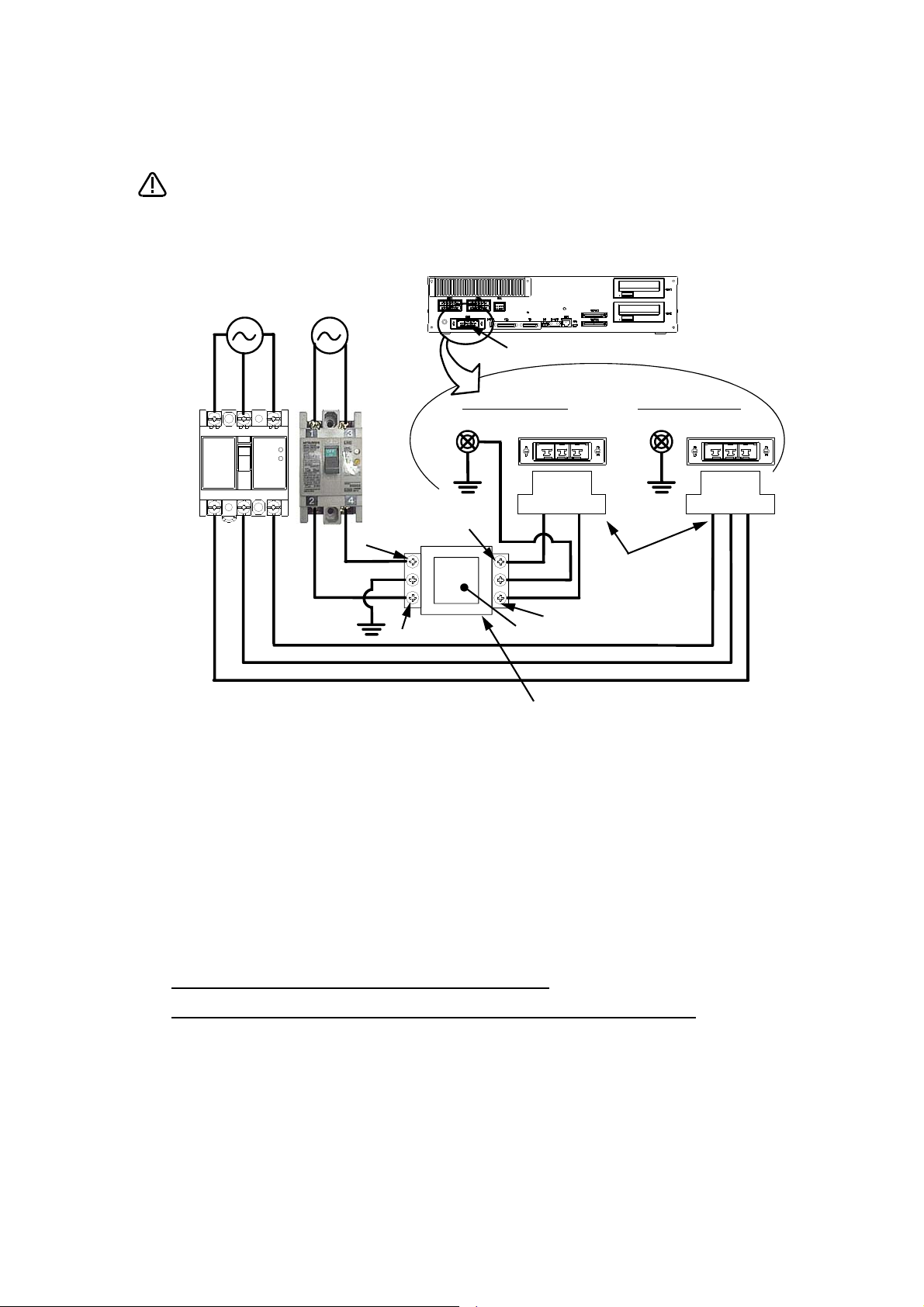
*CR751-D or CR751-Q controller
CAUTION
PE terminal
Grounding screw
Controller
ACIN connector
AC200V AC200V
Primary
Secondary
PE terminal
Grounding screw
123 123
ACIN connector
ACIN connector
Note 2)
Note 1) Crimping swage is recommended for connecting the attachment ACIN connector (soldering is also possible)
Recommendation compression tools: 234171-1(Tyco Electronics)
Note 2) The earth leakage breaker is the customer preparation. Always use the cover below.
Recommendation: For single primary power supply .........NV30FAU-2P-10A-AC100-240V-30mA, (Cover: TCS-05FA2)
For three primary power supply .......... NV30FAU-3P-10A-AC100-240V-30mA, (Cover: TCS-05FA3)
Note 3) If necessary, as shown in the figure, connects the noise filter between ACIN terminal blocks and primary power supply.
(Recommended noise filter: SUP-EL20-ER6 *OKAYA ELECTRIC INDUSTRIES)
Controller
<4> LINE/LOAD
<3> LINE/LOAD
<1> LINE/LOAD
<2> LINE/LOAD
Noise filter
Label
ACIN connector or
power cable
(Attachment)
Note 1)
For three phaseFor single phase
Three phase Single phase
Earth leak-
age breaker
(NV)
Note 3)
* The controller is an
example.
Notes of the basic component are shown.
Please install the earth leakage breaker in the primary side supply power supply
of the controller of CR751-D or CR751-Q because of leakage protection.
1) Please prepare the following: Leakage current breaker (with the terminal cover), cable for connecting the
primary power supply (AWG #14 (2mm
2
or above).
(3.5mm
The secondary power cable (with the ACIN connector) for single phase or three phase power is supplied with
the product to match the specifications. When you build a cable suitable for your environment using the ACIN
connector and the ACIN terminal supplied, prepare a secondary power cable (AWG #14 (2mm
2) Confirm that the primary power matches the specifications.
3) Confirm that the primary power is OFF and that the earth leakage breaker power switch is OFF.
4) Connect the secondary power cable.
a) When using the supplied power cable with the ACIN connector
Refer to the figure above and connect the cable from the secondary side of the earth leakage breaker.
b) When building a power cable using the ACIN connector and the ACIN terminals supplied
Connect the ACIN terminals with the secondary power cable (prepared by customers), and insert the ACIN
terminals to the ACIN connector pins with the following numbers. Crimping caulking is recommended to
connect the ACIN terminals.
For single phase: 1 and 3
For three phase: 1, 2, and 3
Refer to the figure above and connect the cable from the secondary side of the earth leakage breaker.
5) Connect this ACIN connector to the ACIN connector on the front of the controller.
6) Connect the grounding cable to the PE terminal. (M4 screw)
7) Connect the primary power cable to the primary side terminal of the earth leakage breaker.
2
or above), cables to ground the primary power supply (AWG #12
2
) or above).
Page 7
Be careful of interference with peripheral equipment.
CAUTION
Short cut
Arch movement (example)
Especially don't give a shock to the shaft (J3 axis). When you install the
hand, be careful not to knock at the shaft end by the hammer etc. The shaft
may be damaged.
Take care also of the following items.
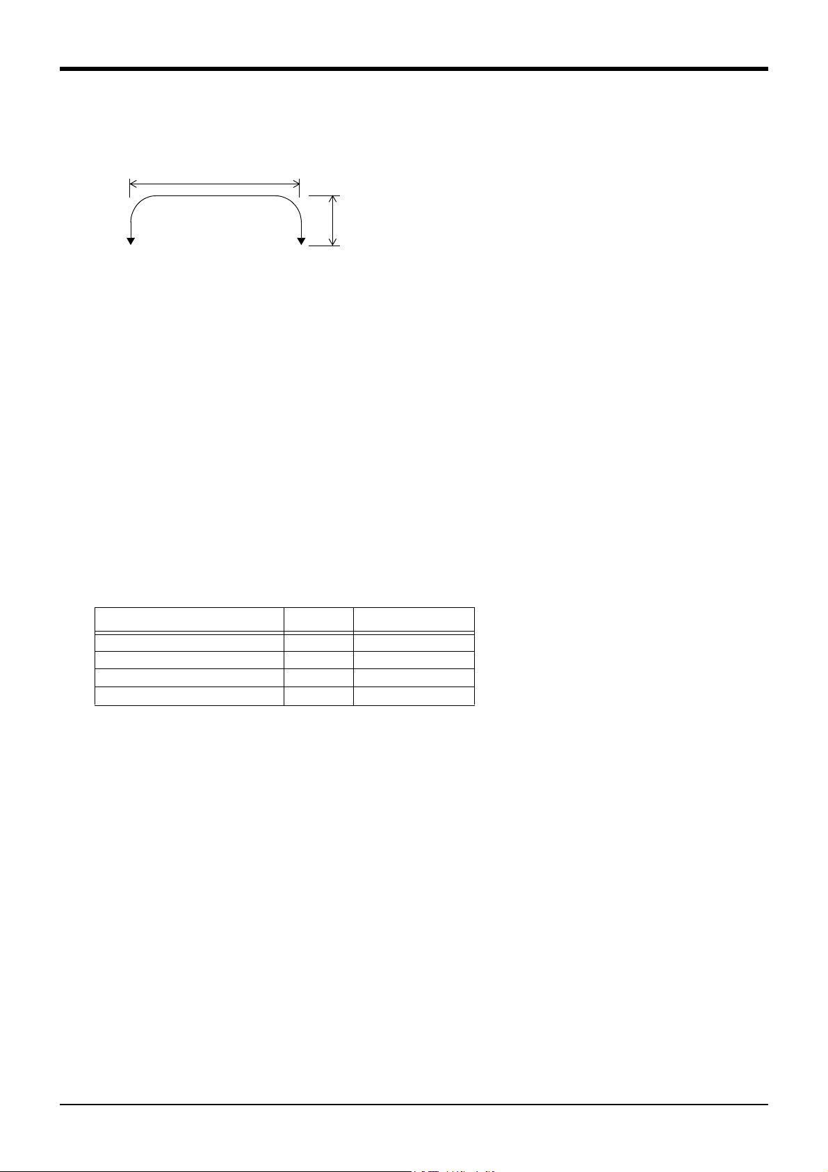
(1)The robot's locus of movement may change with specified speed.
Especially as for the corner section, short cut distance may change. Therefore, when beginning automatic operation, moves at low speed at first, and you should gather speed slowly with
being careful of interference with peripheral equipment.
(2)It can be confirmed whether the specified position exist in the defined area by using the instruc-
tion command "Zone". It can utilize as one of the methods for collision evasion. Refer to the
"detailed description of the instructions manual/function, and operation" of the separate volume
for the details of the instruction command.
Page 8

■Revision history
Date of print Specifications No. Details of revisions
2012-03-13 BFP-A8878
2012-03-21 BFP-A8878-A
2012-04-04 BFP-A8878-B
2012-05-17 BFP-A8878-C
2012-06-05 BFP-A8878-D
2012-09-03 BFP-A8878-E
2012-10-04 BFP-A8878-F
2012-10-11 BFP-A8878-G
2012-11-20 BFP-A8878-H
2013-01-11 BFP-A8878-J
2013-02-15 BFP-A8878-K
2013-07-19 BFP-A8878-M
2013-09-19 BFP-A8878-N
・First print.
・ The painting color was corrected. (Error in writing)
・ Notes were added to the example of safety measures. (The measure against the noise, The
electric specification of the output terminal)
・ CE marking specification was added.
・ The position repeatability was corrected (improvement).
・ ON voltage/ON current and OFF voltage/ OFF current of the parallel input-and-output
interface were corrected (error in writing).
・ The mechanical stopper position to change the operating range to +/-130 degree was
corrected to N12 (Error in writing)
・ Limitation of the electric current value of the relays (coil) connected to the external
emergency stop input was added.
・ The connection method of the Fig.3-27 : AXMC terminal connector (CR750) corrected to
"soldering."
・ The description of the capability value of pose repeatability was deleted.
・ The connector name of hand input signal/output signal of "Fig.2-24: Wiring and piping for
hand" was corrected.
・ The power supply capacity was corrected.
・ The notes were added to "Fig 3-24: Example of EMC noise filter installation".
・ The lithium battery (ER6) was added to The United Nations’Recommendations on the
Transport of Dangerous Goods.
・ The notes about installation of the controller and the robot arm were added. (neither direct
rays nor the heat of lighting)
・ “Table 1-1: Combination of the robot arm and the controller” was corrected.
・ The statement about trademark registration was added.
・ The notes about the input-output connected to the controller were added. (do not ground
the + side of 24V power supply prepared by customer)
・ ”Declaration of Incorporation” was updated.
・ The metal plate which fixes "Hand internal wiring and piping set (option)" was changed to
attachment of the robot arm in standard.
・ EC-Statement of Compliance was updated.
・ Note of the external emergency stop were added (opens the connector terminal at factory
shipping).
・ The connectors of RH-3FH series machine cable (AMP1, AMP2, BRK) were combined as
CN1 connector.
・ Type names of machine cables (option, special specifications) were changed. (No-CE
specification)
・ Type name of CR751 controller was corrected. (formerly: CR751-03HD-0)
・ The simple spanner for resin nuts was added to the attachments of the external wiring/
piping box (option).
・ ”Declaration of Incorporation” and “EC-Statement of Compliance” were updated.
・ ”Fig.2-28: Wiring and piping system diagram for hand and example the solenoid valve
installation” was modified.
・The cautions of operating in a low temperature environment or after a prolonged stop in ”6.3
Precautions for handling” were modified.
・ The caution about fumigation of wood packing was added to ”6.3 Precautions for handling”.
・ ”Fig.6-11: Limitations when connecting the relay etc. (CR750)” and ”Fig.6-12: Limitations
when connecting the relay etc. (CR751)” were corrected.
(Error output → Emergency stop output, Contactor controleoutput for additional axes →
Error output)
・ The descriptions of CR751-03HD1-0-S15 (CE marking specification controller) were added.
・ Type name of CR751 controller was corrected. (formerly: CR751-03HD)
・ The dimensions of screw hole position for fixing user wiring/p
・ The following descriptions of (5) in ”Fig.2-24 : Wiring and piping for hand” were corrected.
The power source wire only for the multifunctional hand → Spare wire
The connector pins name of robot side and connector name of counter side were added.
The connector pins name of counter side was corrected.
・ The descriptions of solenoid valve set were corrected, and explanations were added.
・ ”Fig.2-28 : Wiring and piping system diagram for hand and example the solenoid valve
installation” was corrected.
・ The useable length from the shaft end of Internal Wiring/Piping set for hand was corrected.
・ The descriptions about the ventilation duct which the robot of clean specification has were
corrected.
iping were added.
Page 9

Date of print Specifications No. Details of revisions
2014-01-08 BFP-A8878-P
2014-03-31 BFP-A8878-R
2014-08-20 BFP-A8878-S
2014-12-17 BFP-A8878-T
2015-02-10 BFP-A8878-U
・ The cable fixation plate was added to ”Fig.3-4: Outside dimensions of controller (CR751)”.
・ The type name of the stopper for changing the operating range (J1 axis) in “Table 1-3: The
list of robot option equipment and special specification” was corrected. (formerly: 1S-DH-
02)
・ ”Fig. 2-5: Relationship of the offset length and maximum velocity” was corrected.
・ Conditions for the flexed type cables were corrected.
・ The note about an ambient temperature was added to “2.1.1 Basic specifications”.
・ The station numbers of the parallel I/O interface and the parallel I/O unit was corrected.
・ The description of "MELFA BASIC
controller”.
・ The grounding representation was corrected.
・ The types of the ACIN terminal were added.
・ The dimension of pilot holes for positioning pin was added.
・ The cover and corporate logo mark of this manual was changed.
・ The statement about trademark registration was modified.
・ The explanation of CR751 controller was modified.
・ The description about screw holes using for tooling wiring and piping was added.
・ The note of turning ON the power supply for control (DCcable-2) for parallel I/O unit was
added.
・ A safety relay in “example of safety measures (wiring example 5) ” both CR750 and
CR751 controller were changed.
・ ”Declaration of Incorporation” and “EC-Statement of Compliance” were updated.
・ Allowance value of the offset amount was added to "2.2.2 Mass capacity".
・ The description of how to change the operating range moved into “INSTRUCTION MAN-
UAL/ROBOT ARM SETUP & MAINTENANCE”.
・ Correction of errors in the Specifications discussion materials. (Network vision sensor: 4D-
2CG5***-PKG was deleted.)
・ The corporate logo mark of illustrations in this manual was changed.
・ The description in case the ethernet cable is used as a backup wiring for data communica-
tion was added.
IV
" was added to “Table 3-1: Specifications of
.
Page 10

■ Introduction
・ No part of this manual may be reproduced by any means or in any form, without prior consent from Mit-
subishi.
・ The contents of this manual are subject to change without notice.
・ The specifications values are based on Mitsubishi standard testing methods.
・ The information contained in this document has been written to be accurate as much as possible.
Please interpret that items not described in this document "cannot be performed." or "alarm
may occur".
Please contact your nearest dealer if you find any doubtful, wrong or skipped point.
・ This specifications is original.
・ Microsoft, Windows, Windows XP, Windows Vista, Windows 7, Windows 8, Windows 8.1 are either regis-
tered trademarks or trademarks of Microsoft Corporation in the United States and/or other countries.
・ The official name of Windows® is Microsoft®Windows®Operating System.
・ Windows®XP、 Windows Vista®、 Windows® 7、 Windows® 8、 Windows® 8.1 are either product names of
Microsoft Corporation in the United States.
・ Ethernet is registered trademarks or trademarks of Xerox Corporation in the United States.
・ All other company names and production names in this document are the trademarks or registered
trademarks of their respective owners.
Copyright(C) 2012-2015 MITSUBISHI ELECTRIC CORPORATION
This series offers small-size industrial robots developed using Mitsubishi's latest technology. They are
especially designed to handle and assemble mechanical parts. They are Mitsubishi's answer to the customer's need to achieve a compact manufacturing facility capable of highly flexible production, as necessitated by the diffusion of high-density product groups and the shorter product life cycles that have
become common-place in recent years.
However, to comply with the target application, a work system having a well-balanced robot arm, peripheral devices or robot and hand section must be structured.
When creating these standard specifications, we have edited them so that the Mitsubishi robot's characteristics and specifications can be easily understood by users considering the implementation of robots.
However, if there are any unclear points, please contact your nearest Mitsubishi branch or dealer.
Mitsubishi hopes that you will consider these standard specifications and use our robots.
Note that in this specification document the specifications related to the robot arm is described Page 9,
"2 Robot arm", the specifications related to the controllerPage 63, "3 Controller", and software functions
and a command list Page 130, "4 Software" separately.
This document has indicated the specification of the following types robot.
*RH-3FH-D series
・ About CE Marking in the automization system
The Guidelines of the measures against EMC in the automization system manufactured by the customer is shown in Page 154, "6.4 EMC installation guideline".
Please refer to it and carry out the measures against EMC of the automization system of the customer.
Page 11

Contents
Page
1 General configuration .................................................................................................................................................................... 1-1
1.1 Structural equipment ............................................................................................................................................................. 1-1
1.1.1 Standard structural equipment .................................................................................................................................. 1-1
1.1.2 Special specifications .................................................................................................................................................... 1-1
1.1.3 Options ................................................................................................................................................................................. 1-1
1.1.4 Maintenance parts ........................................................................................................................................................... 1-1
1.2 Model type name of robot .................................................................................................................................................... 1-2
1.2.1 How to identify the robot model ................................................................................................................................ 1-2
1.2.2 Combination of the robot arm and the controller .............................................................................................. 1-3
1.3 CE marking specifications .................................................................................................................................................... 1-3
1.4 Indirect export .......................................................................................................................................................................... 1-3
1.5 Instruction manuals ................................................................................................................................................................ 1-3
1.6 Contents of the structural equipment ............................................................................................................................ 1-4
1.6.1 Robot arm ........................................................................................................................................................................... 1-4
1.6.2 Controller ............................................................................................................................................................................ 1-5
1.7 Contents of the Option equipment and special specification .............................................................................. 1-6
2 Robot arm ........................................................................................................................................................................................... 2-9
2.1 Standard specifications ........................................................................................................................................................ 2-9
2.1.1 Basic specifications ........................................................................................................................................................ 2-9
(1) Standard specification ............................................................................................................................................... 2-9
(2) Clean specification ................................................................................................................................................... 2-11
2.1.2 The counter-force applied to the installation surface ................................................................................... 2-12
2.2 Definition of specifications ................................................................................................................................................ 2-13
2.2.1 Pose repeatability .......................................................................................................................................................... 2-13
2.2.2 Mass capacity .................................................................................................................................................................. 2-14
2.2.3 Relationships Among Mass Capacity, Speed, and Acceleration/Deceleration Speed ...................... 2-15
(1) Setting Load Capacity and Size (Hand Conditions) .................................................................................... 2-15
2.2.4 Vibrations at the Tip of the Arm during Low-Speed Operation of the Robot ..................................... 2-15
2.2.5 Vibration of shaft (J3 axis) position and arm end ............................................................................................ 2-16
(1) Relationship Between Mass Capacity and Speed ..............
(2) Relationship Between Height of Shaft (J3 Axis) and Acceleration/Deceleration Speed ........... 2-17
(3) Relation between offset length and the maximum speed ......................................................................... 2-18
(4) Time to reach the position repeatability ......................................................................................................... 2-19
2.2.6 Collision detection ......................................................................................................................................................... 2-19
2.2.7 Protection specifications ............................................................................................................................................ 2-20
(1) Types of protection specifications .................................................................................................................... 2-20
2.2.8 Clean specifications ...................................................................................................................................................... 2-20
(1) Types of clean specifications ............................................................................................................................... 2-20
2.3 Names of each part of the robot .................................................................................................................................... 2-22
2.4 Outside dimensions ・ Operating range diagram ........................................................................................................ 2-23
2.4.1 Outside dimensions ・ Operating range diagram ................................................................................................ 2-23
(1) Standard Specification ............................................................................................................................................ 2-23
(2) Clean Specification ................................................................................................................................................... 2-29
2.4.2 Mechanical interface and Installation surface ................................................................................................... 2-35
2.4.3 Outside dimensions of machine cables ................................................................................................................ 2-36
(1) Connection with the CR750 controller ............................................................................................................ 2-36
(2) Connection with the CR751 controller ............................................................................................................ 2-36
2.5 Tooling ........................................................................................................................................................................................ 2-37
2.5.1 Wiring and piping for hand .......................................................................................................................................... 2-37
2.5.2 Internal air piping ............................................................................................................................................................ 2-38
(1) Standard type ............................................................................................................................................................. 2-38
(2) Clean type .................................................................................................................................................................... 2-38
2.5.3 Internal wiring for the hand output cable ............................................................................................................ 2-38
2.5.4 Internal wiring for the hand input cable ................................................................................................................ 2-38
2.5.5 Ethernet cable ............................................................................................................................................................... 2-38
......................................................................... 2-16
i
Page 12

Contents
Page
2.5.6 About the Installation of Tooling Wiring and Piping (Examples of Wiring and Piping) ....................... 2-39
(1) Example of wiring and piping <1> ........................................................................................................................ 2-40
(2) Wiring and piping example <2> ............................................................................................................................. 2-40
(3) Precautions for the clean specification ........................................................................................................... 2-41
2.5.7 Wiring and piping system diagram for hand ......................................................................................................... 2-42
2.5.8 Electrical specifications of hand input/output .................................................................................................. 2-43
2.5.9 Air supply circuit example for the hand ............................................................................................................... 2-44
2.6 Shipping special specifications, options, and maintenance parts ...................................................................... 2-45
2.6.1 Shipping special specifications ................................................................................................................................. 2-45
(1) Machine cable ............................................................................................................................................................. 2-46
2.7 Options ....................................................................................................................................................................................... 2-47
(1) Machine cable extension ........................................................................................................................................ 2-48
(2) Changes J1 axis operating range ....................................................................................................................... 2-52
(3) Solenoid valve set ..................................................................................................................................................... 2-53
(4) Hand input cable ........................................................................................................................................................ 2-55
(5) Hand output cable ..................................................................................................................................................... 2-56
(6) Hand curl tube ............................................................................................................................................................ 2-57
(7) Internal Wiring/Piping set for hand .................................................................................................................... 2-58
(8) External Wiring/Piping box .................................................................................................................................... 2-59
2.8 About Overhaul ...................................................................................................................................................................... 2-61
2.9 Maintenance parts ................................................................................................................................................................. 2-62
3 Controller .......................................................................................................................................................................................... 3-63
3.1 Standard specifications ...................................................................................................................................................... 3-63
3.1.1 Basic specifications ...................................................................................................................................................... 3-63
3.1.2 Protection specifications and operating supply ................................................................................................ 3-64
3.2 Names of each part .............................................................................................................................................................. 3-65
3.2.1 Controller .......................................................................................................................................................................... 3-65
(1) CR750 controller ....................................................................................................................................................... 3-65
(2) CR751 controller ....................................................................................................................................................... 3-67
3.3 Outside dimensions/Installation dimensions .............................................................................................................. 3-69
3.3.1 Outside dimensions ....................................................................................................................................................... 3-69
(1) CR750 controller ....................................................................................................................................................... 3-69
(2) CR751 controller ....................................................................................................................................................... 3-70
3.3.2 Installation dimensions ................................................................................................................................................. 3-71
(1) CR750 controller ....................................................................................................................................................... 3-71
(2) CR751 controller ....................................................................................................................................................... 3-73
3.4 External input/output .......................................................................................................................................................... 3-75
3.4.1 Types .................................................................................................................................................................................. 3-75
3.5 Dedicated input/output ...................................................................................................................................................... 3-76
3.6 Emergency stop input and output etc. ......................................................................................................................... 3-79
3.6.1 Connection of the external emergency stop ...................................................................................................... 3-79
(1) CR750 controller ....................................................................................................................................................... 3-80
(2) CR751 controller ....................................................................................................................................................... 3-84
3.6.2 Special stop input (SKIP) ........................................................................................................................................... 3-87
(1) CR750 controller ....................................................................................................................................................... 3-87
(2) CR751 controller ....................................................................................................................................................... 3-88
3.6.3 Door switch function .................................................................................................................................................... 3-89
3.6.4 Enabling device function ............................................................................................................................................. 3-89
(1) When door is opening ............................................................................................................................................... 3-89
(2) When door is closing ................................................................................................................................................ 3-90
(3) Automatic Operation/Jog Operation/Brake Release and Necessary Switch Settings .............. 3-90
3.7 Mode changeover switch input ........................................................................................................................................ 3-91
(1) Specification of the key switch interface ....................................................................................................... 3-91
(2) Connection of the mode changeover switch input ..................................................................................... 3-92
3.8 Additional Axis Function ..................................................................................................................................................... 3-93
ii
Page 13

Contents
Page
3.8.1 Wiring of the Additional Axis Interface ................................................................................................................. 3-93
(1) CR750 controller ....................................................................................................................................................... 3-93
(2) CR751 controller ....................................................................................................................................................... 3-94
3.9 Magnet contactor control connector output (AXMC) for addition axes ........................................................ 3-97
(1) CR750 controller ....................................................................................................................................................... 3-98
(2) CR751 controller ....................................................................................................................................................... 3-98
3.10 Options .................................................................................................................................................................................... 3-99
(1) Teaching pendant (T/B) ...................................................................................................................................... 3-100
(2) Parallel I/O interface ............................................................................................................................................ 3-103
(3) External I/O cable .................................................................................................................................................. 3-108
(4) Parallel I/O unit ...................................................................................................................................................... 3-110
(5) External I/O cable .................................................................................................................................................. 3-121
(6) CC-Link interface .................................................................................................................................................. 3-123
(7) RT ToolBox2/RT ToolBox2 mini ...................................................................................................................... 3-126
(8) Instruction Manual (bookbinding) ..................................................................................................................... 3-128
3.11 Maintenance parts ........................................................................................................................................................... 3-129
4 Software ......................................................................................................................................................................................... 4-130
4.1 List of commands ............................................................................................................................................................... 4-130
4.2 List of parameters .............................................................................................................................................................. 4-133
5 Instruction Manual ..................................................................................................................................................................... 5-135
5.1 The details of each instruction manuals ................................................................................................................... 5-135
6 Safety .............................................................................................................................................................................................. 6-136
6.1 Safety ...................................................................................................................................................................................... 6-136
6.1.1 Self-diagnosis stop functions ................................................................................................................................ 6-136
6.1.2 External input/output signals that can be used for safety protection measures ........................... 6-137
6.1.3 Precautions for using robot .................................................................................................................................... 6-137
6.1.4 Safety measures for automatic operation ........................................................................................................ 6-138
6.1.5 Safety measures for teaching ............................................................................................................................... 6-138
6.1.6 Safety measures for maintenance and inspections, etc. ........................................................................... 6-138
6.1.7 Examples of safety measures ................................................................................................................................ 6-139
(1) CR750 controller ..........................................
(2) CR751 controller .................................................................................................................................................... 6-144
(3) External emergency stop connection [supplementary explanation] ................................................. 6-149
6.2 Working environment ......................................................................................................................................................... 6-152
6.3 Precautions for handling .................................................................................................................................................. 6-152
6.4 EMC installation guideline ............................................................................................................................................... 6-154
6.4.1 Outlines ........................................................................................................................................................................... 6-154
6.4.2 EMC directive ............................................................................................................................................................... 6-154
6.4.3 EMC measures ............................................................................................................................................................. 6-155
6.4.4 Component parts for EMC measures ................................................................................................................. 6-155
(1) Ferrite core ............................................................................................................................................................... 6-155
(2) Line noise filter ....................................................................................................................................................... 6-155
7Appendix ........................................................................................................................................................................... Appendix-156
Appendix 1 : Specifications discussion material ........................................................................................ Appendix-156
.......................................................................................................... 6-139
iii
Page 14

1General configuration
1 General configuration
1.1 Structural equipment
Structural equipment consists of the following types.
1.1.1 Standard structural equipment
The following items are enclosed as a standard.
(1) Robot arm
(2) Controller
(3) Machine cable
(4) Robot arm installation bolts
(5) Safety manual, CD-ROM (Instruction manual)
(6) Guarantee card
1.1.2 Special specifications
For the special specifications, some standard configuration equipment and specifications have to be changed
before factory shipping. Confirm the delivery date and specify the special specifications at the order.
1.1.3 Options
User can install options after their delivery.
1.1.4 Maintenance parts
Materials and parts for the maintenance use.
1-1
Structural equipment
Page 15

1General configuration
1.2 Model type name of robot
This robot has arranged the type name corresponding to load mass, arm length, and environment specification.
Details are shown below, please select the robot suitable for the customer's use.
1.2.1 How to identify the robot model
RH - 3 FH □□ △△ ○ - 1 D ▲ - Sxx
(a) (b) (c) (d) (e) (f) (g) (h) ( i ) ( j )
(a). RH..............................................Indicates the horizontal multiple-joint robot.
(b). 3..................................................Indicates the maximum load.
3: 3kg
(c). FH..............................................Indicates the FH series.
(d). □□ ..........................................Indicates the arm length.
Ex.)
35: 350mm
45: 450mm
55: 550mm
(e). △△ ..........................................Indicates the vertical stroke length.
Ex.)
12: 120mm stroke
15: 150mm stroke
(f). ○ ................................................Indicates environment specification.
Ex.)
Omitted: General specifications
C: Clean specifications
(g). 1..................................................Indicates the controller series.
Ex.)
Omitted: CR750 controller
1: CR751 controller
(h). D.................................................Indicates the controller type.
D: Stand alone type
(i). ▲.................................................Technical standard of Conformity.
Ex.)
Omitted: No conformity of technical standard.
1: Conforms to the CE Marking
(j). - S xx ....................................Indicates a special model. In order, limit special specification.
Model type name of robot
1-2
Page 16
1General configuration
1.2.2 Combination of the robot arm and the controller
Table 1-1 : Combination of the robot arm and the controller
Protection specification
General-purpose environment RH-3FH3515-1D 350
Clean specifications RH-3FH3512C-1D 350
Robot arm
RH-3FH4515-1D 450
RH-3FH5515-1D 550
RH-3FH5512C-1D 550
1.3 CE marking specifications
The robot shown in Table 1-2 is the CE Marking specification.
Table 1-2 : Robot models with CE marking specifications
Robot type
RH-3FHxxyy-D1-S15
RH-3FHxxyyC-D1-S15
RH-3FHxxyy-1D1-S15
RH-3FHxxyyC-1D1-S15
Note1)
Note3)
Note3)
CR750-03HD1-1-S15
CR751-03HD1-0-S15
Controller External signal logic Language setting
Note2)
Note4)
Arm
length
(mm)
J3-axis stroke
(mm)
150
120RH-3FH4512C-1D 450
Source type English (ENG)
Controller
CR751-03HD-0
Note1) The "xx" indicate the arm length, "yy"indicate J3-axis stroke.
Note2) The specification and the handling method of the controller are the same as standard type controller CR750-03HD-1.
Note3) This robot is the clean specification. As long as there is no special description, refers to the contents of RH-3FHxxyyC
(clean specification).
Note4) The specification and the handling method of the controller are the same as standard type controller CR751-03HD-0.
1.4 Indirect export
The display in English is available by setting parameter LNG as "ENG."
1.5 Instruction manuals
The instruction manuals supplied in CD-ROM, except for the Safety Manual. This CD-ROM (electronic manual)
includes instruction manuals in both Japanese and English versions.
1-3
CE marking specifications
Page 17
1.6 Contents of the structural equipment
* Refer to Page 9, "2.1 Standard specifica-
tions" for details on the specifications.
Horizontal four-axis multiple-jointed type
(RH-3FH series)
Hand output cable
・ 1F-GR60S-01 (4sets)
Hand input cable
・ 1F-HC35C-01
Hand curl tube
・ 1E-ST0408C-300
Machine cable extension
CR751 controller
・ Fixed type: 1F- □□ UCBL-02 (direct type)
・Flexed type: 1F-□□LUCBL-02 (direct type)
CR750 controller
・ Fixed type: 1S- □□ CBL-03 (extension type)
・ Flexed type: 1S- □□ LCBL-03 (extension type)
・ Flexed type: 1S- □□ LUCBL-03 (direct type)
Note1) □□ refer the length. Refer to Table 1-3 for details.
Machine cable (Fix type : 2m)
・ CR751 controller: 1F-02UCBL-02
・ CR750 controller: 1S-02UCBL-03
Solenoid valve set
・ 1F-VD0*-01 (Sink type)
・ 1F-VD0*E-01 (Source type)
(*: 1 to 4 = 1 set to 4 set)
*With hand output cable.
Machine cable
(Standard product:
5m attachment)
Pneumatic hand
customer-manufactured parts
[Caution]
Standard configuration
Special specifications
Option
equipment
Prepared by customer
Changes J1 axis operating range
・ 1F-DH-01
Internal Wiring/Piping set for hand
・ 1F-HS304S-01
This option
External Wiring/Piping box
・1F-UT-BOX
Pull out Wiring/Piping
This option
For CR751 controller
For CR750 controller
1.6.1 Robot arm
The list of structural equipment is shown in below.
Fig.1-1 : Structural equipment
Contents of the structural equipment
1-4
Page 18
1 General configuration
Personal computer
Prepared by customer
*)Refer to Table
1-5 for USB
cable
Instruction Manual (bookbinding)
・ 5F-FA01-PE01
Parallel I/O interface
2D-TZ368(Sink)/
2D-TZ378(Source)
CC-Link interface
2D-TZ576
Teaching pendant (T/B)
Simple T/B
・ R32TB: For CR750 controller
・ R33TB: For CR751 controller
Highly efficient T/B
・ R56TB: For CR750 controller
・ R57TB: For CR751 controller
Controller
・ CR751-03HD-0
・ CR751-03HD1-0-S15
・ CR750-03HD1-1-S15
External I/O cable
・ 2D-CBL05 (5m)
・ 2D-CBL15 (15m)
Parallel I/O unit
2A-RZ361(Sink)/
2A-RZ371(Source)
External I/O cable
・ 2A-CBL05 (5m)
・ 2A-CBL15 (15m)
RT ToolBox2/RT ToolBox2 mini
RT ToolBox2
・ 3D-11C-WINE(CD-ROM)
(Windows XP、 Windows Vista、 Windows 7、
Windows 8、 Windows 8.1)
RT ToolBox2 mini
・ 3D-12C-WINE(CD-ROM)
(Windows XP、 Windows Vista、 Windows 7、
Windows 8、 Windows 8.1)
PLC (Programmable
Logic Controller)
External device
Prepared by customer
Standard configuration
Special specifications
Options
Prepared by
equipment
customer
1.6.2 Controller
The devices shown below can be installed on the controller.
The controllers that can be connected differ depending on the specification of the robot. (Refer to Page 2, "1.2
Model type name of robot".)
Fig.1-2 : Structural equipment
1-5
Page 19

1.7 Contents of the Option equipment and special specification
A list of all Optional equipment and special specifications are shown below.
1 General configuration
Table 1-3 : The list of robot option equipment and special specification
Item Type Specifications
Stopper for changing the
operating range (J1 axis)
Machine cable
(Replaced to shorter cable)
Machine cable extension
(extension type)
Machine cable extension
(direct type)
Solenoid valve set 1F-VD01-01/VD01E-01 1 set (Sink type)/(Source type)
Hand input cable 1F-HC35C-01 Robot side: connector.
Hand output cable
Hand curl tube 1E-ST0408C-300 For solenoid valve 4set.:Φ4x8
1F-DH-01
1S-02UCBL-03 For fixing (Set of power and sig-
1F-02UCBL-02 For fixing (Set of power and sig-
1S- □□ CBL-03 For fixing (Set of power and sig-
1S- □□ LCBL-03 For flexing (Set of power and
1S- □□ LUCBL-03 For flexing (Set of power and
1F- □□ UCBL-02 For fixing (Set of power and sig-
1F- □□ LUCBL-02 For flexing (Set of power and
1F-VD02-01/VD02E-01 2 set (Sink type)/(Source type)
1F-VD03-01/VD03E-01 3 set (Sink type)/(Source type)
1F-VD04-01/VD04E-01 4 set (Sink type)/(Source type)
1F-GR60S-01
The stopper parts for J1 axis
nal)
nal)
nal)
signal)
signal)
nal)
signal)
Hand side: wire.
Robot side: connector
Hand side: wire
Classification
Note1)
CR750 CR751
○○
○・□
-
○-
○-
○-
-○
-○
○ ○
○ ○
○ ○
○ ○
○○
○○
○○
-
○・□
Description
This must be installed by the customer.
2m
(A 2m cable is supplied instead of the
5m cable that is supplied as standard)
" □□ " in type shows the length of the
cables as follows.
05=5m, 10=10m, 15=15m
" □□ " in type shows the length of the
cables as follows.
10=10m, 15=15m, 20=20m
The solenoid-valve set for the hand of
the customer setup
1F-VD0*-01: Sink type
1F-VD0*E-01: Source type
The cable is connected to the sensor by
the customer.
Attaches the cable clamp (drip proof
type)
The cable is connected to the hand out-
put connector by the customer.
Attaches the cable clamp (drip proof
type)
Straight cable 600mm (total length)
Curl type air tube
External Wiring/Piping box 1F-UT-BOX For solenoid valve 4set.:Φ4x8
Internal Wiring/Piping set
for hand
1F-HS304S-01 Hand input cable (four signal
lines and two power lines), φ3
four hoses
○○
○○
Box which pulls out the Wire/Piping
(Hand I/O cable, Hand curl tube)
Wiring/Piping to pass in the shaft
Reducers (φ4 to φ3: 8pcs) are
Attached.
Note1) Distinction of ○ (is option) and □ (is special specification at shipping) is shown for each pair with the
controller.
Contents of the Option equipment and special specification
1-6
Page 20

1
General configuration
Table 1-4 : The list of controller option equipment and special specification
Classification
Item Type Specifications
Simple teaching pendant R32TB Cable length 7m ○ - With 3-position enable switch IP65
R32TB-15 Cable length 15m ○ R33TB Cable length 7m - ○
R33TB-15 Cable length 15m - ○
Highly efficient teaching
pendant
Parallel I/O Interface 2D-TZ368
External I/O cable
(For Parallel I/O Interface)
Parallel I/O Unit 2A-RZ361
External I/O cable
(For Parallel I/O Unit)
CC-Link interface 2D-TZ576 Only Intelligent device station,
RT ToolBox2
(Personal computer Sup-
port software)
RT ToolBox2 mini
(Personal computer Sup-
port software mini)
Instruction Manual
R56TB Cable length 7m ○ R56TB-15 Cable length 15m ○ R57TB Cable length 7m - ○
R57TB-15 Cable length 15m - ○
DO: 32 point
(Sink type)
2D-TZ378
(Source type)
2D-CBL05
2D-CBL15
(Sink type)
2A-RZ371
(Source type)
2A-CBL05 5m ○ ○ Use to connect the external peripheral
2A-CBL15 15m ○ ○
3D-11C-WINE CD-ROM
3D-12C-WINE CD-ROM
5F-FA01-PE01 RH-3FH-D series
DI: 32 point
Insulated type output signal
(0.1A/24V /point)
DO: 32 point/
DI: 32 point
Insulated type output signal
(9mA/ 24V /point)
5m
15m
DO: 32 point/
DI: 32 point
Insulated type output signal
(0.1A/24V /point)
DO: 32 point/
DI: 32 point
Insulated type output signal
(7mA/ 24V /point)
Local station
Note1)
CR750 CR751
○○
○○
○○
○○
○○
○○
○○
○○
Description
The card type external input-and-output.
Interface. Install to the slot of controller.
Use to connect the external peripheral
device to the parallel input/output
interface.
The unit for expansion the external
input/output.
Electrical isolated Type
(100mA/Point)
device to the parallel input/output unit
For MELSEC PLC with CC-Link connection.
Windows XP、 Windows Vista、 Windows
7、 Windows 8、 Windows 8.1
(With the simulation function)
Windows XP、 Windows Vista、 Windows
7、 Windows 8、 Windows 8.1
Note1) Distinction of ○ (is option) and □ (is special specification at shipping) is shown for each pair with the
controller.
1-7
Contents of the Option equipment and special specification
Page 21
Caution
Caution
[Reference]:The recommendation products of the USB cable are shown below
Table 1-5 : Recommendation article of the USB cable
Name Type name Supplier
USB cable
(USB A type-USB mini B type)
USB adapter
(USB B type-USB mini B type)
Be careful to the USB cable to apply neither the static electricity nor the noise.
Otherwise, it becomes the cause of malfunction.
Use the network equipments (personal computer, USB hub, LAN hub, etc) confirmed by manufacturer.
The thing unsuitable for the FA environment (related with conformity, temperature or noise) exists in
the equipments connected to USB. When using network equipment, measures against the noise, such
as measures against EMI and the addition of the ferrite core, may be necessary. Please fully confirm
the operation by customer. Guarantee and maintenance of the equipment on the market (usual office
automation equipment) cannot be performed.
KU-AMB530 SANWA SUPPLY INC.
USB-M53 ELECOM CO., LTD.
GT09-C30USB-5P
MR-J3USBCBL3M MITSUBISHI ELECTRIC CO., LTD.
AD-USBBFTM5M ELECOM CO., LTD.
MITSUBISHI ELECTRIC SYSTEM & SERVICE CO.,
LTD.
1 General configuration
Contents of the Option equipment and special specification
1-8
Page 22

2Robot arm
2 Robot arm
2.1 Standard specifications
2.1.1 Basic specifications
(1) Standard specification
Table 2-1 : Standard specifications of robot arm
Item Unit
Type
Environment Standard specification
Installation posture On floor
Degree of freedom 4
Structure Horizontal, multiple-joint type
Drive system AC servo motor
Position detection method Absolute encoder
Motor capacity J1 W 200
J2 W 100
J3 (Z) W 100
J4 (θaxis) W 50
Brake J1, J2, J4: no brake, J3: with brake
Arm length № 1 arm
№2 arm
Max.reach radius( № 1+ № 2)
Operating range J1 deg ±170
J2 deg ±145
J3 (Z)
J4 (θaxis) deg ±360
Note1)
Speed of motion
Maximum horizontal composite speed
Note2)
Cycle time
Load
Z axis pressing force
Note4)
Allowable inertia Rating
Pose repeatability
Ambient temperature
Mass
Tool wiring ・ Input 8 points/Output 8 points, (total 20 cores)
Tool pneumatic pipes Primary: φ6 x two hoses, Secondary: φ4 x eight hoses
Supply pressure MPa 0.5±10%
Protection specification
Painting color Light gray (Equivalent to Munsell: 0.6B7.6/0.2)
Note3)
J1 deg/s 400
J2 deg/s 720
J3 (Z) mm/s 1,100
J4 (θaxis) deg/s 3,000
Rating
Maximum 3
Maximum N 82
Maximum 0.06
Note5)
X-Y
direction
J3 (Z)
J4 (θaxis) deg ±0.004
Note6)
Note9)
mm
mm
mm
mm
mm/s
sec 0.41 0.46 0.51
kg
(N)
2
kg ・ m
mm
mm
℃0 to 40
k
RH-3FH3515 RH-3FH4515 RH-3FH5515
125
350
6,800 7,500 8,300
±0.010 ±0.010 ±0.012
29
・ Dedicated signal cable for multifunctional hand (Two cores + Power cable two cores)
・ Ethernet cable one cable (100BASE-TX, eight cores)
Note1) The maximum speed is the value which applied MvTune2 (high-speed movement mode).
Note2) At the maximum speed on the X-Y flat surface in the robot's control point, it is obtained with each speed of J1, J2,
and J4. The control point is the position offset by the rated inertia from the flange.
Specifications
225 325
225
450 550
150
1
0.005
±0.010
32
Note7)
Note8)
IP20
2-9
Standard specifications
Page 23

300
25
Note3) The value of the following movement which applied MvTune2 (high-speed movement mode) with the carrying mass of
2kg.
・ The cycle time may increase with the case where the positioning accuracy of the work etc. is necessary, or by the
moving position.
Note4) This is the downwards pressing force that occurs at the end of the load when the maximum load is on board and the
J1, J2 and J4 axis are in their resting state. Please operate at this level or below. When pressing for long periods of
time, an excess load error may occur. Please operate in a manner that does not cause errors.
Note5) The pose repeatability details are given in Page 13, "2.2.1 Pose repeatability".
Note6) Sets the robot's operating environmental temperature as parameter OLTMX. Corresponding to the environment, the con-
tinuous control action performance and the overload-protection function are optimized. (Refers to "Optimizing the overload level" described in "Chapter 5 Functions set with parameters" of separate instruction manual/ Detailed
explanations of functions and operations for details.)
Note7) The 8-wire cable designated for LAN wiring can also be used for backup wiring.
Note8) The φ4 secondary piping can be obtained with the electromagnetic valve (option). Details regarding the electromag-
netic valve (optional) are shown on Page 53, "(3) Solenoid valve set".
Note9) The protection specification details are given in Page 20, "2.2.7 Protection specifications".
2Robot arm
Standard specifications
2-10
Page 24

2Robot arm
(2) Clean specification
Table 2-2 : Standard specifications of robot arm (Clean specification)
Item Unit
Type
Environment Standard specification
Installation posture On floor
Degree of freedom 4
Structure Horizontal, multiple-joint type
Drive system AC servo motor
Position detection method Absolute encoder
Motor capacity J1 W 200
J2 W 100
J3 (Z) W 100
J4 (θaxis) W 50
Brake J1, J2, J4: no brake, J3: with brake
Arm length № 1 arm
№2 arm
Max.reach radius( № 1+ № 2)
Operating range J1 deg ±170
J2 deg ±145
J3 (Z)
J4 (θaxis) deg ±360
Note1)
Speed of motion
Maximum horizontal composite speed
Note2)
Cycle time
Load
Z axis pressing force
Note4)
Allowable inertia Rating
Pose repeatability
Ambient temperature
Mass
Tool wiring ・ Input 8 points/Output 8 points, (total 20 cores)
Tool pneumatic pipes Primary: φ6 x two hoses, Secondary: φ4 x eight hoses
Supply pressure MPa 0.5±10%
Protection specification
Painting color Light gray (Equivalent to Munsell: 0.6B7.6/0.2)
Note3)
J1 deg/s 420
J2 deg/s 720
J3 (Z) mm/s 1,100
J4 (θaxis) deg/s 3,000
Rating
Maximum 3
Maximum N 82
Maximum 0.06
Note5)
X-Y
direction
J3 (Z)
J4 (θaxis) deg ±0.004
Note6)
Note9)
mm
mm
mm
mm
mm/s
sec 0.41 0.46 0.51
kg
(N)
2
kg ・ m
mm
mm
℃0 to 40
k
RH-3FH3512C RH-3FH4512C RH-3FH5512C
125
350
6,800 7,500 8,300
±0.010 ±0.010 ±0.012
29
・ Dedicated signal cable for multifunctional hand (Two cores + Power cable two cores)
・ Ethernet cable one cable (100BASE-TX, eight cores)
Note1) The maximum speed is the value which applied MvTune2 (high-speed movement mode).
Note2) At the maximum speed on the X-Y flat surface in the robot's control point, it is obtained with each speed of J1, J2,
and J4. The control point is the position offset by the rated inertia from the flange.
Specifications
225 325
225
450 550
120
1
0.005
±0.010
32
Note7)
Note8)
Clean specification: ISO class 3
2-11
Standard specifications
Page 25
300
25
Note3) The value of the following movement which applied MvTune2 (high-speed movement mode) with the carrying mass of
2kg.
・ The cycle time may increase with the case where the positioning accuracy of the work etc. is necessary, or by the
moving position.
Note4) This is the downwards pressing force that occurs at the end of the load when the maximum load is on board and the
J1, J2 and J4 axis are in their resting state. Please operate at this level or below. When pressing for long periods of
time, an excess load error may occur. Please operate in a manner that does not cause errors.
Note5) The pose repeatability details are given in Page 13, "2.2.1 Pose repeatability".
Note6) Sets the robot's operating environmental temperature as parameter OLTMX. Corresponding to the environment, the con-
tinuous control action performance and the overload-protection function are optimized. (Refers to "Optimizing the overload level" described in "Chapter 5 Functions set with parameters" of separate instruction manual/ Detailed
explanations of functions and operations for details.)
Note7) The 8-wire cable designated for LAN wiring can also be used for backup wiring.
Note8) The φ4 secondary piping can be obtained with the electromagnetic valve (option). Details regarding the electromag-
netic valve (optional) are shown on Page 53, "(3) Solenoid valve set".
Note9) The details of the clean specifications are described in Page 20, "2.2.8 Clean specifications". The conditions neces-
sary to guarantee cleanliness are as follows: clean room down flow greater then 0.3 m/s, robot internal suction of 30
to 50 L/min, and installation of an exhaust duct at the rear of the robot’s main base. A φ8 joint has been prepared
at the rear of the base for suction.
The protection specification details are given in Page 20, "2.2.7 Protection specifications".
2Robot arm
2.1.2 The counter-force applied to the installation surface
The counter-force applied to the installation surface for the strength design of the robot installation surface is
shown.
Table 2-3 : Value of each counter-force
Item Unit Value
Falls moment: M
Torsion moment: M
Horizontal translation force: F
Vertical translation force: F
L
T
V
H
N ・ m 240
N ・ m 255
N 810
N 380
Standard specifications
2-12
Page 26

2 Robot arm
2.2 Definition of specifications
The accuracy of pose repeatability mentioned in catalogs and in the specification manual is defined as follows.
2.2.1 Pose repeatability
For this robot, the pose repeatability is given in accordance with JIS B 8432 (Pose repeatability). Note that the
value is based on 100 measurements (although 30 measurements are required according to JIS).
[Caution] The specified "pose repeatability" is not guaranteed to be satisfied under the following conditions.
[1] Operation pattern factors
1) When an operation that approaches from different directions and orientations are included in relation to the teaching position during repeated operations
2) When the speed at teaching and the speed at execution are different
[2] Load fluctuation factor
1) When work is present/absent in repeated operations
[3] Disturbance factor during operation
1) Even if approaching from the same direction and orientation to the teaching position, when the
power is turned OFF or a stop operation is performed halfway
[4] Temperature factors
1) When the operating environment temperature changes
2) When accuracy is required before and after a warm-up operation
[5] Factors due to differences in accuracy definition
1) When accuracy is required between a position set by a numeric value in the robot's internal coordinate system and a position within the actual space
2) When accuracy is required between a position generated by the pallet function and a position
within the actual space
2-13
Definition of specifications
Page 27
定格慣性モーメント
最大慣性モーメント
シャフト中心
単位:mm
20mm(1kg)
100mm(3kg以下)
Unit: mm
Shaft center
Allowable moment of inertia
Maximum
Rating
100mm (less than 3kg)
2 Robot arm
2.2.2 Mass capacity
The robot's mass capacity is expressed solely in terms of mass, but even for tools and works of similar mass,
eccentric loads will have some restrictions When designing the tooling or when selecting a robot, consider the following issues.
(1) The tooling should have the value less or equal than the smaller of the allowable moment of inertia found in
Page 9, "2.1.1 Basic specifications".
(2) Fig. 2-1 shows the distribution dimensions for the center of gravity in the case where the volume of the
load is relatively small. Use this figure as a reference when designing the tooling.
Please use the robot in the allowable moment of inertia of maximum moment of inertia shown in Fig. 2-1.
[Caution]The mass capacity is greatly influenced by the operating speed of the robot and the motion posture.
Even if you are within the allowable range mentioned previously, a vibration, an overload or generate an
overcurrnt alarm could occur. In such cases, please reduce acceleration and deceleration (Accel command) speeds and movement speed (Ovrd command). Although the standard value to reduce is 50% for
each command, please adjust corresponding to the movement posture. Refer to separate "Instruction
Manual/Detailed Explanation of Functions and Operations" for details of each command.
Moreover, if hand/workpiece parameters are not set exactly, the similar phenomenon will be easier to
occur.
[Caution] Refer to Page 15, "2.2.3 Relationships Among Mass Capacity, Speed, and Acceleration/Deceleration
Speed", and set the values of the mass, magnitude, and distance to the centroid of a tool and a workpiece
to parameters.
If parameters are not set exactly, the lifetime of reduction gears, a belt, etc. is affected.
[Caution] The overhang amount of the load, such as the mass capacity and the allowable moment of inertia
defined in this section, are dynamic limit values determined by the capacity of the motor that drives axes
or the capacity of the speed reducer. Therefore, it does not guarantee the accuracy on all areas of tooling.
Guaranteed accuracy is measured from the center point of the mechanical interface surface. Please note
that if the point of operation is kept away from the mechanical interface surface by long and low-rigid
tooling, the positioning accuracy may deteriorate or may cause vibration.
Note that the allowable offset value (Z direction) from the lower edge of the shaft to the position of center
of gravity is 100 mm.
[Caution] Even within the allowable range previously mentioned, an overload alarm may be generated if an ascend-
ing operation continues at a micro-low speed. In such a case, it is necessary to increase the ascending
speed.
[Caution] This robot will restrict speed automatically by internal controls when the load center-of-gravity position
separates from the shaft center. Refer to Page 15, "2.2.3 Relationships Among Mass Capacity, Speed, and
Acceleration/Deceleration Speed" in detail.
The allowance distance (allowance offset amount) from the center of the shaft to the gravity center of
loading weight is 100mm.
Fig.2-1 : Position of center of gravity for loads (for loads with comparatively small volume)
2-14
Page 28

2 Robot arm
2.2.3 Relationships Among Mass Capacity, Speed, and Acceleration/Deceleration Speed
This robot automatically sets the optimum acceleration and deceleration speeds and maximum speed, according
to the load capacity and size that have been set, and operates using these automatically set speeds.
To achieve that, it is necessary to correctly set the actual load data (mass and size of hand and work) to be used.
However, vibration, overheating and errors such as excessive margin of error and overload may occur, depending
on the robot operation pattern or ambient temperature.
In this case, reduce the speed and the acceleration and deceleration rate before continuing to use. This is done by
accessing the robot program and adjusting the speed settings (Ovrd) and the acceleration and deceleration settings (Accel).
If a setting is performed in such a way that it falls below the mounted load, the life span of the mechanism elements used in the robot may be shortened. In the case of a work requiring a high degree of accuracy, set up the
load correctly and use the robot by lowering the ratios of the acceleration and deceleration speeds.
(1) Setting Load Capacity and Size (Hand Conditions)
Set up the capacity and size of the hand with the "HNDDAT*" parameter (optimum acceleration/deceleration
setting parameter), and set up the capacity and size of the work with the "WRKDAT*" parameter. Numbers 0 to 8
can be used for the asterisk (*) part. Designate the "HNDDAT*" and "WRKDAT*" parameters to be used using
the "LoadSet" command in a program.
For more details, refer to the separate "Instruction Manual/Detailed Explanation of Functions and Operations."
It is the same meaning as "LoadSet 0.0" if not using the "LoadSet".
<Factor default settings>
HNDDAT*
WRKDAT*
Hand masskgsize X
mm
3.0 99.0 99.0 76.0 0.0 0.0 38.0
0.0 0.0 0.0 0.0 0.0 0.0 0.0
size Y
mm
size Zmmcenter-of-gravity
position X mm
center-of-gravity
position Y mm
center-of-gravity
position Z mm
Note) The position of the center of gravity is located at the center of the surface at the bottom of the shaft. Set
the X, Y and Z center of gravity positions for the tool coordinate directions (the Z center of gravity position
will be a plus for downward directions).
2.2.4 Vibrations at the Tip of the Arm during Low-Speed Operation of the Robot
Vibrations at the tip of the arm may increase substantially during the low-speed operation of the robot, depending
on the combination of robot operation, hand mass and hand inertia. This problem occurs when the vibration count
specific to the robot arm and the vibration count of the arm driving force are coming close to each other. These
vibrations at the tip of the arm can be reduced by taking the following measures:
1) Change the robot's operating speed by using the Ovrd command.
2) Change and move the teaching points of the robot.
3) Change the hand mass and hand inertia.
2-15
Page 29

100
60
0
0
1
最大速度割合
負荷質量(kg)
3
(%)
RH-3FH series
Maximum speed ratio (%)
Load capacity (kg)
2 Robot arm
2.2.5 Vibration of shaft (J3 axis) position and arm end
Vibrations at the tip of the arm may increase substantially during operation under the shaft position near the
low end or the high end of the robot, depending on the combination of hand mass and hand inertia. This problem
occurs according to that inertia, because the distance from the shaft support section to the shaft end becomes
long. When this vibration affects the robot's operations, please change operating speed etc. like the above Page
15, "2.2.4 Vibrations at the Tip of the Arm during Low-Speed Operation of the Robot".
(1) Relationship Between Mass Capacity and Speed
A function to optimize the maximum speed of each axis according to the setting value of the load capacity will be
activated (Refer to Fig. 2-2).
However, this function does not work with the setting of 1kg or lighter load mass. When the setting of the load
mass is changed to 1kg or heavier, the maximum speed is compensated according to the load mass.
[CAUTION] Depending on the operation pattern, the speed and/or acceleration/deceleration at the front edge
may not be parallel with the speed and the rate of change of acceleration/deceleration specified in a
program.
Fig.2-2 : Automatic compensation of speed
2-16
Page 30
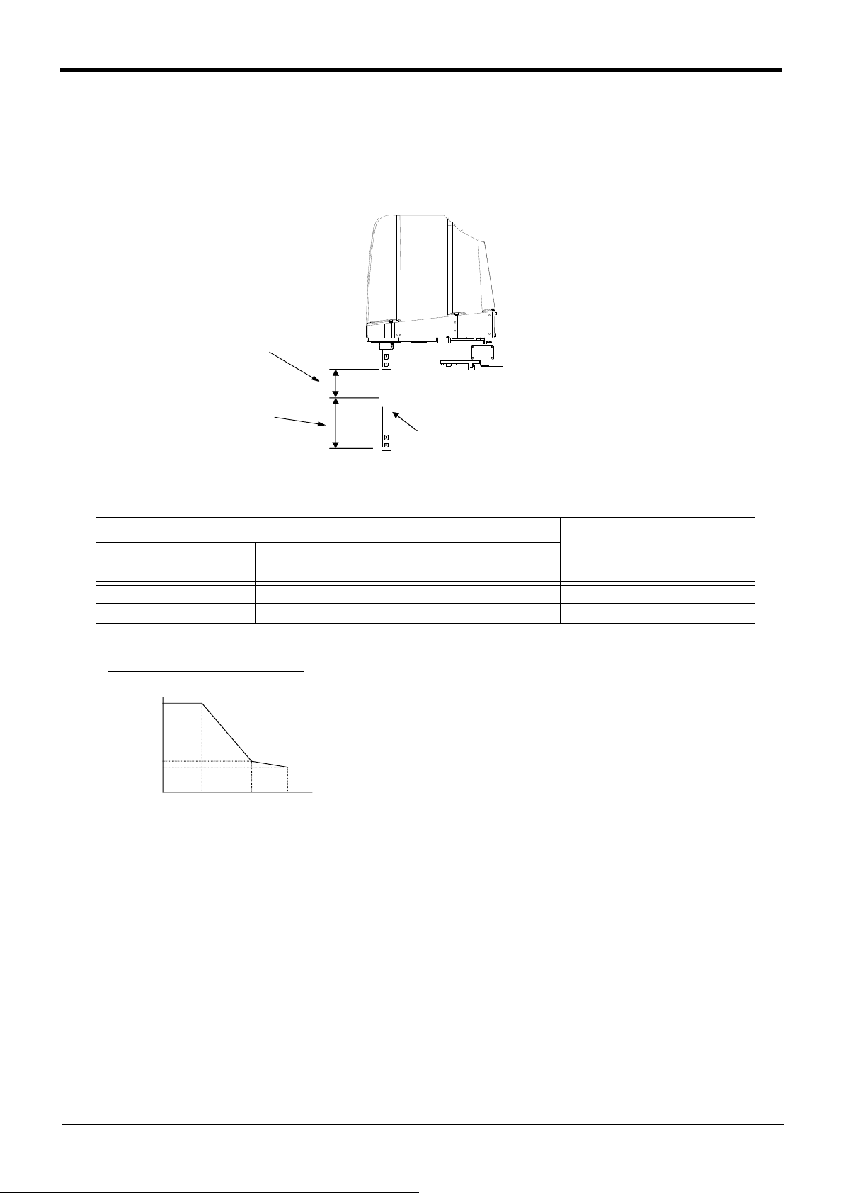
2 Robot arm
P3
→
→
シャフト(J3軸)
速度、加減速度を
補正しない領域
速度、加減速度を
補正する領域
P1
P2
Shaft (J3 axis)
Area in which speed and
acceleration/deceleration
speed are not compensated
Area in which speed and
acceleration/deceleration
speed are compensated
加減速度割合
100
36
0
370
310
220
シャフト位置(mm)
(%)
250
24
J3 axis (Z) stroke 120mm/150mm
Acceleration/decelera-
tion speed ratio(%)
Shaft position (mm)
(Standard Acceleration/deceleration speed)
(2) Relationship Between Height of Shaft (J3 Axis) and Acceleration/Deceleration Speed
A function to optimize the acceleration/deceleration speed according to the height of the shaft (Refer to Fig. 2-3,
Fig. 2-4) will be activated. This function is invalid if the shaft (axis J3) operates at a position above P3 in Fig. 2-3.
Acceleration/deceleration is compensated for at a position below P3 in Fig. 2-3 if the position of the center of
gravity of the load is located at the front edge of the shaft.
Fig.2-3 : Area in which acceleration/deceleration speed is compensated
Table 2-4 : Area in which acceleration/deceleration speed is compensated
J3 axis stroke (mm)
Stroke length
120 340 220 220 ~ 310
150 370 220 220 ~ 310
P1
(Upper end)
P2
(Lower end)
Fig.2-4 : Automatic compensation of acceleration/deceleration speed
Compensation area
(P2 to P3)
2-17
Page 31

加減速度割合
100
42
0
0
100
オフセット量(mm)
(%)
40
60
60
Acceleration/deceleration
speed ratio(%)
Offset length (mm)
Tact time/
1
cycle
O
peration time
Wait time
B
A
Increased acceleration/deceleration speed
x Accel instruction [%] x parameter JADL [%]
Acceleration/deceleration speed [m/sec
2
]
= optimum acceleration/deceleration speed [m/sec
2
]
2 Robot arm
(3) Relation between offset length and the maximum speed
A function to optimize the maximum speed of each axis according to the offset length will be activated. (Refer to
Fig. 2-5)
Fig.2-5 : Relationship of the offset length and maximum velocity
[Supplementary explanation 1]: The setting which shortens execution time
The execution time can be improved by using the following methods.
1) Perform continuous path operation using the Cnt command.
2) Control the optimum acceleration/deceleration using the Oadl command.
3) Control the optimum speed using the Spd command.
4) Setting a larger value in the optimum acceleration/deceleration adjustment rate parameter: JADL. (Maximum 100)
The moving time can be shortened by setting a larger value in the optimum acceleration/deceleration adjustment rate
parameter (JADL). In this robot, the acceleration/deceleration speed is initialized to allow continuous moving with a
short wait time (setting of B in the Fig. 2-6).
This setting is suited for continuous operations that have a short tact time, such as palletizing work.
Conversely, if quick moves (short moving time) are required, such as L/UL work on machined parts, the acceleration/
deceleration speed can be increased by initial setting (setting of A in the Fig. 2-6).
However, please note that some setting values of acceleration/deceleration speed tend to cause overload and overheat
errors. In such a case, extend the wait time, reduce the acceleration/deceleration speed, or decrease the moving speed.
Fig.2-6 : Relationship between Acceleration/deceleration Speed and Tact Time (Conceptual Drawing)
2-18
Page 32

2 Robot arm
A
100mm
以上
B
②
①
O
More than 100mm
(4) Time to reach the position repeatability
When using this robot, the time to reach the position repeatability may be prolonged due to the effect of residual
vibration at the time of stopping. If this happens, take the following measures:
1) Change the operation position of the Z axis to the location near the top as much as possible.
2) Increase the operation speed prior to stopping.
3) When positioning the work near the bottom edge of the Z axis, if no effectiveness is achieved in step "2)"
above, perform operation ① (robot path: O → A → C). In the case of operation ② (robot path: O → B →
C), residual vibration may occur. (Refer to Fig. 2-7.)
Fig.2-7 : Recommended path when positioning at the bottom edge of the Z axis
2.2.6 Collision detection
This series have the "collision detection function" which detects the abnormalities by the collision of the robot
arm, and the initial setting has set this function as the enable to suppress damage to the minimum.
Although the enable/disable of this function can be changed by parameter: COL and command: ColChk, you
should use in valid condition of this function for protection of the robot and of the peripheral equipment.
The abnormalities are detected by the robot's kinetics model, presuming torque necessary for movement at any
time. Therefore, the setting parameter (HNDDAT*, WRKDAT*) of the hand and the work piece conditions should
be right. And, it may be detected as the collision in movement as speed and motor torque are changed rapidly. (for
example, the movement near the place of the origin by linear interpolation, the reversal movement, the cold condition, the operation after long term stoppage)
In such a case, by adjusting the value of the setting parameter (COLLVL, COLLVLJG) of the collision detection
level according to actual use environment, the sensitivity of collision detection can be optimized and the damage
risk can be reduced further. And, in the operation after the low temperature or long term stoppage, please operate
by accustoming at low speed (warm-up), or use the warm-up operation mode.
Refer to the separate instruction manual "Detailed explanations of functions and operations" for details of related
parameter.
Table 2-5 : Factory-shipments condition
JOG operation Automatic
RH-3FH series Valid Invalid
2-19
Page 33

2 Robot arm
2.2.7 Protection specifications (1) Types of protection specifications
The robot arm has protection specifications that comply with the IEC Standards. The protection specifications
and applicable fields are shown in Table 2-6.
Table 2-6 : Protection specifications and applicable fields
Type
RH-3FHxx15
The IEC IP symbols define the degree of protection against solids and fluids, and do not indicate a protective
structure against the entry of oil.
The IEC standard is described by the following "Information" And, the corrosion of the rust etc. may occur to the
robot with the liquids.
【Information】
・ The IEC IP20
It indicates the protective structure that prevents an iron ball 12
with the power of 3.1 kg±10%, from going through the opening in the outer sheath of the supplied equipment.
Protection
specifications
(IEC Standards value)
Robot arm: IP20
Classification Applicable field Remarks
General-purpose
environment specifications
General assembly
Slightly dusty environment
+0.05
mm diameter, which is being pressed
0
2.2.8 Clean specifications (1) Types of clean specifications
The robot arm with clean specification is made by order. Please check the delivery schedule.
Table 2-7 : Clean specifications
Type Degree of cleanliness Internal suction Remarks
RH-3FHxx12C
Note1) The conditions necessary to guarantee cleanliness are as follows: clean room down flow greater then 0.3 m/s,
robot internal suction of 30 to 50 L/min, and installation of an exhaust duct at the rear of the robot’s main base. A
φ8 joint has been prepared at the rear of the base for suction.
ISO class 3
Note1)
・ Suck the inside of robot arm with
vacuum pump. (prepared by customer)
・ Use it in the clean room with the
down flow (flow velocity 0.3 m/s
above).
■ Precautions for use
1) A φ8 VACUUM coupling is provided in the base section of the robot arm for vacuum inside the robot arm.
(Refer to Fig. 2-23) When using the robot, connect this coupling with the vacuum generating valve (Refer to
Table 2-8) and vacuum pump (furnished by the customer).
2) To suck in the robot arm, use the vacuum generator of the specification shown in following a) and b).
a) When using the vacuum generator
Table 2-8 : Specifications of vacuum generation valve (Confirmed in our company)
Type Maker
MEDT 14 KOGANEI CORPORATION ・ Vacuum rate: 90.0 L/min(ANR)
Air pressure
Note1)
The use of a vacuum generating valve
is recommended.
Quantity
1
Note1) It is the vacuum pump maker's written specification.
b) When using the vacuum pump
Assure the vacuum flow rate of 30-50L/min. And, secure the exhaust course from the pump not to affect
the power supply and the cleanness for the vacuum pumps.
2-20
Page 34

2 Robot arm
Robot base
Internal suction
Opening
Machine cable
Ventilation duct
3) The ventilation duct is attached to the robot arm rear (refer to Fig. 2-8). As the Z axis moves up and down
the volume of the bellows varies, and air is sucked in and released out of the robot’s ventilation duct
opening. Be sure to locate the ventilation duct’s opening in a position that will not affect the robot’s cleanliness.
Furthermore, whilst it is only a small amount, internal suction results in external air flows into the robot
through the ventilation duct’s opening, and therefore the following two points should be considered when
deciding where to locate the ventilation duct’s opening.
・ The opening should be facing downwards
・ The opening should not be located in the vicinity of dust/dirt or liquids, etc.
(Recommended cleanliness of surrounding area: less than ISO class 5)
Fig.2-8 : Installation of Ventilation Duct
4) When using the optional electromagnetic valve set, we recommend using the primary piping’s spare piping
(φ6 air hose) to release the exhaust fumes.
Please take care as leaking exhaust fumes inside the robot may have an impact on the robot’s cleanliness.
2-21
Page 35

2.3 Names of each part of the robot
ベース
第2アーム
J4軸
+
-
J2軸
+
-
J1軸
+
-
第1アーム
J3軸
+
-
シャフト
ブレーキ解除スイッチ
ブレーキ解除スイッチ
View A
Note 1) The operation method of the brake release switch.
The brake of J3 axis can be released with this switch and the enabling
switch of T/B.
Please be sure to perform brake release operation by two-person
operations. Always assign an operator other than the switch operator to
prevent the arm from dropping. This operation must be carried out with the
switch operator giving signals.
When releasing the brake the J3 axis will drop. Be
sure to perform brake release operation by two-
person operations.
(1) One person supports so that the J3 axis may not drop.
(2) The one more person pushes the brake release switch of the robot arm, in the
condition that the enabling switch of T/B is turned on.
CAUTION
Brake release switch
No.1 arm
No.2 arm
J1 axis
J2 axis
Base
J3 axis
Shaft
J4 axis
T/B
Enabling switch
(Hold down to the left or the right.)
Brake release switch
A
Note1)
2 Robot arm
Fig.2-9 : Names of each part of the robot
Names of each part of the robot
2-22
Page 36

2 Robot arm
Note
*1) Indicates the space necessary
to replace the battery.
*2) Indicates screw holes (M4 depth
6mm) for fixing user wiring/
piping. Six places on both-sides
of No.2 arm, Two places on
front surface.
*3) The distance to a minimum
bendable radius of the machine
cable for CR750/751 controller.
*4) Indicates the space necessary
to connect the machine cable
for CR750/751 controller.
Note) The drawing shows an example of the CR751 controller connection robot.
Note) Refer to Fig. 2-22 for the mechanical interface section and installation base section dimensions.
2.4 Outside dimensions ・ Operating range diagram
2.4.1 Outside dimensions ・ Operating range diagram (1) Standard Specification
Fig.2-10 : Outside dimensions of RH-3FH3515
2-23
Outside dimensions ・ Operating range diagram
Page 37

Installation surface
2 Robot arm
Fig.2-11 : Operating range diagram of RH-3FH3515
Outside dimensions ・ Operating range diagram
2-24
Page 38

2 Robot arm
Note
*1) Indicates the space necessary
to replace the battery.
*2) Indicates screw holes (M4 depth
6mm) for fixing user wiring/
piping. Six places on both-sides
of No.2 arm, Two places on
front surface.
*3) The distance to a minimum
bendable radius of the machine
cable for CR750/751 controller.
*4) Indicates the space necessary
to connect the machine cable
for CR750/751 controller.
Note) The drawing shows an example of the CR751 controller connection robot.
Note) Refer to Fig. 2-22 for the mechanical interface section and installation base section dimensions.
Fig.2-12 : Outside dimensions of RH-3FH4515
2-25
Outside dimensions ・ Operating range diagram
Page 39

Installation surface
2 Robot arm
Fig.2-13 : Operating range diagram of RH-3FH4515
Outside dimensions ・ Operating range diagram
2-26
Page 40

2 Robot arm
Note
*1) Indicates the space
necessary to replace the
battery.
*2) Indicates screw holes (M4
depth 6mm) for fixing user
wiring/piping. Six places on
both-sides of No.2 arm, Two
places on front surface.
*3) The distance to a minimum
bendable radius of the
machine cable for CR750/
751 controller.
*4) Indicates the space neces-
sary to connect the machine
cable for CR750/751 controller.
Note) The drawing shows an example of the CR751 controller connection robot.
Note) Refer to Fig. 2-22 for the mechanical interface section and installation base section dimensions.
Fig.2-14 : Outside dimensions of RH-3FH5515
2-27
Outside dimensions ・ Operating range diagram
Page 41

Installation surface
2 Robot arm
Fig.2-15 : Operating range diagram of RH-3FH5515
Outside dimensions ・ Operating range diagram
2-28
Page 42

2 Robot arm
Note
*1) Indicates the space necessary
to replace the battery.
*2) Indicates screw holes (M4 depth
6mm) for fixing user wiring/
piping. Six places on both-sides
of No.2 arm, Two places on
front surface.
*3) The duct is attached to the
clean specification.
*4) The distance to a minimum
bendable radius of the machine
cable for CR750/751 controller.
*5) Indicates the space necessary
to connect the machine cable
for CR750/751 controller.
Note) The drawing shows an example of the CR751 controller connection robot.
Note) Refer to Fig. 2-22 for the mechanical interface section and installation base section dimensions.
(2) Clean Specification
Fig.2-16 : Outside dimensions of RH-3FH3512C
2-29
Outside dimensions ・ Operating range diagram
Page 43

Installation surface
2 Robot arm
Fig.2-17 : Operating range diagram of RH-3FH3512C
Outside dimensions ・ Operating range diagram
2-30
Page 44

2 Robot arm
Note
*1) Indicates the space necessary
to replace the battery.
*2) Indicates screw holes (M4 depth
6mm) for fixing user wiring/
piping. Six places on both-sides
of No.2 arm, Two places on
front surface.
*3) The duct is attached to the
clean specification.
*4) The distance to a minimum
bendable radius of the machine
cable for CR750/751 controller.
*5) Indicates the space necessary
to connect the machine cable
for CR750/751 controller.
Note) The drawing shows an example of the CR751 controller connection robot.
Note) Refer to Fig. 2-22 for the mechanical interface section and installation base section dimensions.
Fig.2-18 : Outside dimensions of RH-3FH4512C
2-31
Outside dimensions ・ Operating range diagram
Page 45

Installation surface
2 Robot arm
Fig.2-19 : Operating range diagram of RH-3FH4512C
Outside dimensions ・ Operating range diagram
2-32
Page 46

2 Robot arm
Note
*1) Indicates the space necessary
to replace the battery.
*2) Indicates screw holes (M4
depth 6mm) for fixing user
wiring/piping. Six places on
both-sides of No.2 arm, Two
places on front surface.
*3) The duct is attached to the
clean specification.
*4) The distance to a minimum
bendable radius of the
machine cable for CR750/751
controller.
*5) Indicates the space necessary
to connect the machine cable
for CR750/751 controller.
Note) The drawing shows an example of the CR751 controller connection robot.
Note) Refer to Fig. 2-22 for the mechanical interface section and installation base section dimensions.
Fig.2-20 : Outside dimensions of RH-3FH5512C
2-33
Outside dimensions ・ Operating range diagram
Page 47

Installation surface
2 Robot arm
Fig.2-21 : Operating range diagram of RH-3FH5512C
Outside dimensions ・ Operating range diagram
2-34
Page 48

2 Robot arm
<ハンド取り付けフランジ部詳細>
<ベース裏面据付寸法詳細>
92
92
90 120
150
60
2-φ6穴
(φ8位置決めピン用下穴)
4-φ9据付用穴
(据付基準)
(据付基準)
Rz25
Rz25
180
150
174
断面Z-Z
15
15
φ
1
1
貫
通
穴
φ16h7
φ37.5
30
10
10
10
φ90
10
30
10
クリーン仕様
標準仕様
160
<Detail of Mechanical interface>
Standard specification Clean specification
Section Z-Z
φ
1
1
t
h
r
o
u
g
h
h
o
l
e
<Details of installation dimensions>
4-φ9 installation reference hole
(Installation reference surface)
(Installation
reference surface)
2-φ6 hole
Pilot hole (positioning pin φ8)
Note) Don't install the robot arm in the position where direct rays or the heat of lighting hits. The skin temperature of the
robot arm may rise, and the error may occur.
2.4.2 Mechanical interface and Installation surface
Fig.2-22 : Mechanical interface and Installation surface
2-35
Outside dimensions ・ Operating range diagram
Page 49

2.4.3 Outside dimensions of machine cables
㻭㼜㼜㼞㼛㼤㻚㻌䃥㻤㻜
㼇㻯㼛㼚㼠㼞㼛㼘㼘㼑㼞㻌㼟㼕㼐㼑㼉
㼇㻾㼛㼎㼛㼠㻌㼍㼞㼙㻌㼟㼕㼐㼑㼉
㻭㼜㼜㼞㼛㼤㻚㻌㻡㻜
㻭㼜㼜㼞㼛㼤㻚㻌㻣㻜
㻭㼜㼜㼞㼛㼤㻚㻌㻥㻜
㻭㼜㼜㼞㼛㼤㻚㻌䃥㻝㻡
㻭㼜㼜㼞㼛㼤㻚㻌㻥㻜
㻭㼜㼜㼞㼛㼤㻚㻌㻣㻜
㻭㼜㼜㼞㼛㼤㻚㻌㻡㻜
㻭㼜㼜㼞㼛㼤㻚㻌䃥㻤㻜
Note) If using an optional machine cable extension, refer to Page 48, "(1) Machine cable extension" in a diameter of the cable.
Note) If using an optional machine cable extension, refer to Page 48, "(1) Machine cable extension" in a diameter of the cable.
㻭㼜㼜㼞㼛㼤㻚㻌䃥㻤㻤
㼇㻯㼛㼚㼠㼞㼛㼘㼘㼑㼞㻌㼟㼕㼐㼑㼉
㼇㻾㼛㼎㼛㼠㻌㼍㼞㼙㻌㼟㼕㼐㼑㼉
㻡㻤
㻣㻝
㻭㼜㼜㼞㼛㼤㻚㻌㻝㻡
㻭㼜㼜㼞㼛㼤㻚㻌㻠㻡 㻭㼜㼜㼞㼛㼤㻚㻌㻥㻜
㻭㼜㼜㼞㼛㼤㻚㻌㻝㻠㻣
㻭㼜㼜㼞㼛㼤㻚㻌䃥㻝㻡
㻭㼜㼜㼞㼛㼤㻚㻌㻡㻡 㻭㼜㼜㼞㼛㼤㻚㻌㻞㻟
㻭㼜㼜㼞㼛㼤㻚㻌㻝㻞
㻭㼜㼜㼞㼛㼤㻚㻌㻝㻢
㻭㼜㼜㼞㼛㼤㻚㻌㻞㻜
㻭㼜㼜㼞㼛㼤㻚㻌㻡㻝
Note) If using an optional machine cable extension, refer to Page 48, "(1) Machine cable extension" in a diameter of the cable.
㼇㻯㼛㼚㼠㼞㼛㼘㼘㼑㼞㻌㼟㼕㼐㼑㼉
㼇㻾㼛㼎㼛㼠㻌㼍㼞㼙㻌㼟㼕㼐㼑㼉
㻭㼜㼜㼞㼛㼤㻚㻌䃥㻥
㻭㼜㼜㼞㼛㼤㻚㻌㻠㻡
㻣㻝
㻡㻞
㻭㼜㼜㼞㼛㼤㻚㻌㻝㻞
㻭㼜㼜㼞㼛㼤㻚㻌䃥㻤㻡
㻭㼜㼜㼞㼛㼤㻚㻌㻝㻠
㻭㼜㼜㼞㼛㼤㻚㻌㻠㻡
㻭㼜㼜㼞㼛㼤㻚㻌㻠㻜
㻭㼜㼜㼞㼛㼤㻚㻌㻠㻜
㻭㼜㼜㼞㼛㼤㻚㻌㻡㻜
Note) If using an optional machine cable extension, refer to Page 48, "(1) Machine cable extension" in a diameter of the cable.
(1) Connection with the CR750 controller
1) Power cable
2) Signal cable
㻭㼜㼜㼞㼛㼤㻚㻌㻥㻜
㻭㼜㼜㼞㼛㼤㻚㻌㻠㻡
2 Robot arm
㼇㻯㼛㼚㼠㼞㼛㼘㼘㼑㼞㻌㼟㼕㼐㼑㼉
㻭㼜㼜㼞㼛㼤㻚㻌㻠㻡
㻭㼜㼜㼞㼛㼤㻚㻌䃥㻣㻤
㻭㼜㼜㼞㼛㼤㻚㻌㻣㻜
(2) Connection with the CR751 controller
1) Power cable
2) Signal cable
㻭㼜㼜㼞㼛㼤㻚㻌㻥㻜
㻭㼜㼜㼞㼛㼤㻚㻌䃥㻝㻢
㻭㼜㼜㼞㼛㼤㻚㻌㻣㻜
㼇㻾㼛㼎㼛㼠㻌㼍㼞㼙㻌㼟㼕㼐㼑㼉
㻭㼜㼜㼞㼛㼤㻚㻌䃥㻣㻤
Outside dimensions ・ Operating range diagram
2-36
Page 50

2 Robot arm
Connector and pneumatic coupling
No. Name Qty.
Robot side (Robot arm side) Counter side (customer-prepared)
Manufacturer
Connectors,
couplings
Connector pins Connector Connector pins
(1) Coupling 2 UKBL6 - - - Koganei Corporation
(2) Coupling 1 UKBL8 - - - Koganei Corporation
(3) Connector 2 1-1717834-4 1318108-1 1-1318115-4 1318112-1 Tyco Electronics AMP
(4) Connector 2 1-1717834-3 1318108-1 1-1318115-3 1318112-1 Tyco Electronics AMP
(5) Connector 1 1-1318117-3 1318112-1 1-1318120-3 1318108-1 Tyco Electronics AMP
(6) Connector 1 2-1717834-4 1318108-1 2-1318115-4 1318112-1 Tyco Electronics AMP
(7) Connector 1 TM21P-88P - - -
View A
A
(4)Hand input signal connector (HC1, 2)
(3)Hand output signal connector (GR1, 2)
Secondary piping pneumatic hose (Option, or customer prepared)
φ4 hose (Max. 8 hoses)
Primary piping pneumatic hose (AIR OUT, RETURN)
Solenoid valve set (Option)
(3)Hand output signal connector (GR1, 2)
Primary piping pneumatic hose
(AIR OUT, RETURN)
(6)The signal wire only for
the multifunctional hand.
(7)Ethernet cable (8 cores)
(5)Spare wire
* If the LAN connector is cut and connector of
customer preparation is connected, it can be
use as other usages.
Pulling out wiring and piping
Wiring and piping can be passed
through the inside of the shaft.
It can also be pulled out externally
from the rear of the No. 2 arm by
using the Page 59, "(8) External
Wiring/Piping box".
Ethernet cables and the power supply
chord for remote input/output can be
pulled out from the grommet at the
rear of the base section.
Note) On the clean specifications it is
necessary to seal the cable
aperture closed.
(Robot arm side)
(Robot arm side)
No.2 arm
No.1 arm
Robot base
(two cores + two wires)
(two wires)
(1) Primary piping pneumatic
coupling (φ6)
(AIR IN, RETURN)
Cable apertures of Ethernet cable and
signal wire only for the multifunctional hand
(Grommet)
Machine cable connector
(power supply) (AMP1, AMP2)
(Inside the cover)
Machine cable connector
(for signal) (CN2)
(Inside the cover)
(2)Vacuum (VACUUM) (φ8)
(Only for clean specification)
Machine cable connector (for
brake) (BRK)
(Inside the cover)
<Connection with the CR750 controller>
Machine cable connector (for signal)
(CN2)
Machine cable connector (power supply)
(CN1)
Robot arm rear side: View B
<Connection with the CR751 controller>
B
2.5 Tooling
2.5.1 Wiring and piping for hand
Shows the wiring and piping configuration for a standard-equipped hand.
Fig.2-23 : Wiring and piping for hand
2-37
Tooling
Page 51

2.5.2 Internal air piping (1) Standard type
1) The robot has two φ6 urethane hoses from the pneumatic entrance on the base section to the No.2 arm.
One hose is the primary piping for the pneumatic equipment, and the other pipe is used for air exhaust.
2) The pneumatic inlet in the base section has a φ6 pneumatic coupling bridge.
3) The solenoid valve set (optional) can be installed to the side on No.2 arm.
4) Refer to Page 53, "(3) Solenoid valve set" for details on the electronic valve set (optional).
(2) Clean type
1) The primary piping is the same piping as the standard type.
2) With the clean specification, a φ8 coupling is provided in the base section for suction inside the machine.
For use, connect it to the suction port of the vacuum pump or the coupling on the "VACUUM" side of the
vacuum generating valve. Moreover, to clean the exhaust from the vacuum pump or vacuum generator, use
the exhaust filter (prepared by the customer).
3) Refer to Page 20, "2.2.8 Clean specifications" for details of the vacuum for suction.
4) Supply clean air to the vacuum generator.
2.5.3 Internal wiring for the hand output cable
1) The hand output primary cable extends from the connector PCB of the base section to the back side of the
2
No.2 arm. (AWG#24(0.2mm
puts.The connector names are GR1 and GR2.
To pull the wiring out of the arm, following separate options are required.
・ Hand output cable....................................1F-GR60S-01
・ External wiring and piping box.............1F-UT-BOX
): 10 cables) The cable terminals have connector bridges for eight hand out-
2 Robot arm
2.5.4 Internal wiring for the hand input cable
1) The hand input cable extends from the connector PCB of the base section to the No.2 arm.
(AWG#24(0.2mm
nector names are HC1 and HC2.
2) The hand check signal of the pneumatic hand is input by connecting this connector.
To extend the wiring to the outside of the arm, following separate options are required.
・ Hand input cable .......................................1F-HC35C-01
・ External wiring and piping box.............1F-UT-BOX
2.5.5 Ethernet cable Ethernet cables are installed from the robot’s base section up to the No. 2 arm section, and can be used.
Similar to on our previous models, these cables can also be used for backup wiring. For further details please refer
to the separate “Instruction Manual/Robot Arm Setup”.
Example of use for backup wiring.
・ When connecting previously used tools to the robot
・ Folding back the hand output cable when attaching the electromagnetic valve to the robot’s exterior.
・ When attaching 8 devices or more to the hand section such as sensors, (8 input and 8 output dedicated
points are available for hand signals.). In this case connect the signals (of the sensors, etc.) to parallel
input/output signals.
When shipped from the factory, both ends are LAN connectors.
When using it as backup wiring, cut the LAN connectors off and use with user supplied connectors.
When using it as backup wiring for data communication, the shield wire must be grounded. If the shield wire is not
grounded, it may cause a communication abnormality by noise superposed on the cable.
2
): 10 cables) The cable terminals have connector bridges for eight hand inputs. The con-
Table 2-9 : Ethernet cable specification
Item Specification
Communication speed 100BASE-TX
Size
Externality of insulator Approx. 0.98 mm
AWG #26 (0.13mm
2
) x four pair (total eight cores)
Tooling
2-38
Page 52

2 Robot arm
164 102
2-M4深さ6
(反対側にもあり)
10
2-M4深さ8
(反対側にもあり)
2-M4深さ8
(反対側にもあり)
25
55
2-M4深さ8
20
11
110
4
-
M5
ね
じ
深
さ
1
1
B
矢視B
A
矢視A
(Usable on opposite
side too.)
2-M4, depth 8
View B
View A
4
-
M
5
s
c
r
e
w
,
d
e
p
t
h
1
1
2-M4, depth 8
(Usable on opposite
side too.)
2-M4, depth 6
2-M4, depth 8
(Usable on opposite
side too.)
2.5.6 About the Installation of Tooling Wiring and Piping (Examples of Wiring and Piping)
The customer is required to provide tooling wiring, piping and metal fixtures.
Screw holes are provided on the robot arm for the installation of tooling wiring, piping and metal fixtures. (Refer to
the Fig. 2-24.)
The length of wiring and piping and the installation position on the robot must be adjusted according to the work
to be done by the robot. Please use the following example as reference.
<Precautions>
・ A hand input cable and a hand curl cable are available as optional accessories for your convenience.
・ After performing wiring and piping to the robot, operate the robot at low speed to make sure that each part
does not interfere with the robot arm and the peripheral devices.
Confirm that there is no interference also with bellows of the shaft section by clean specification .
・ Please be aware that dust may be generated from friction if wires and pipes come into contact with the robot
arm when using it according to the clean specifications.
・If you install metal fixtures and a solenoid valve using the screw holes on the No.2 arm portion, add the mass of
the metal fixtures and the solenoid valve to mass of a hand then set the HNDDAT parameter. Moreover, Fix
the parts, such as a solenoid valve, firmly to prevent the parts getting shaky during operation of a robot.
Fig.2-24 : Location of screw holes for fixing wiring/piping
2-39
Tooling
Page 53

2次配管エアホースなど
・ケーブル内装配線・配管セット(オプション)
(ハンドチューブ:φ3×4本、ハンド入力ケーブル(信号用4本、電源用2本))
または
・ハンドチューブなど(お客様ご準備)
電磁弁セット(オプション)
1次配管エアホース(AIR OUT、RETURN)(第2アーム内)
ハンド出力信号コネクタ(GR1、GR2)(電磁弁オプション側)
ハンド出力信号コネクタ(GR1、GR2)(第2アーム内)
ケーブル内装配線・配管セット(オプション)用
ケーブル固定板金
お客様ご準備ツール
Solenoid valve set (Option)
Cable fixed plate for Internal Wiring/Piping
set for hand (Option)
Primary piping air hose (AIR OUT, RETURN)
Inside the No.2 arm
Hand output signal connector (GR1, GR2)
(Solenoid valve (option) side)
Hand output signal connector (GR1, GR2)
(Inside the No.2 arm)
Example of the customer
preparation tool
Secondary piping air hose, etc
・ Internal Wiring/Piping set for hand (Option)
(Hand tube: φ3 x 4 hoses, Hand input cable (For signal: 4 cable, For power: 2 cable))
or
・ Hand tube (Customer prepared)
固定金具(お客様準備)
固定金具(お客様準備)
配線・配管(お客様準備)
または
ハンド入力ケーブル(オプション)
外部配線配管ボックス(オプション)
配線・配管(お客様準備)
または
ハンドカールチューブ(オプション)
お客様準備ツール
Example of the customer
preparation tool
Fixing plate (Customer preparation)
Wiring/Piping (Customer preparation)
or
Hand input cable (Option)
External Wiring/Piping box (Option)
Wiring/Piping (Customer preparation)
or
Hand curl tube (Option)
Metal fittings (customer preparation)
2 Robot arm
(1) Example of wiring and piping <1>
By feeding wiring and piping through the inside of the shaft, the wiring and piping to the hand becomes compact.
Fig.2-25 : Example of wiring and piping <1>
(2) Wiring and piping example <2>
This is an effective method in cases where the wiring and piping is often changed, or when the hand rotation is
minimal (within ±90°), etc.
Fig.2-26 : Example of wiring and piping <2>
Tooling
2-40
Page 54

2 Robot arm
(3) Precautions for the clean specification
The through hole of the top part of the tip shaft are taped at shipment.
Perform the following actions as necessary in order to ensure that the robot keeps sufficiently protective
performance during the operation:
1) When the through hole of the shaft is not used
・ Keep the top part of the tip shaft taped while the robot is in use.
2) When the through hole of the shaft is used for wiring.
・ Remove the rubber cap on top of the tip shaft and perform the necessary wiring. Once the wiring is com-
pleted, seal the bottom part of the tip shaft using liquid seal in order to avoid accumulation of dust
・Perform the wiring in such a way that the wires around the area below the tip shaft will not get into contact
with other parts while the robot is operating.
2-41
Tooling
Page 55

白
A1
A2
A3
A4
B1
B2
B3
B4
コントローラ
ロボット本体配線中継ボード
<+24V>
<予約>
<HC 1>
<HC 2>
<HC 3>
<HC 4>
A1
A2
A3
B1
B2
B3
<+24V(COM)>
<GR 1>
<GR 2>
<GR 3>
<GR 4>
A1
A2
A3
A4
B1
B2
B3
B4
<+24V(COM)>
<GR 5>
<GR 6>
<GR 7>
<GR 8>
ハンド信号出力用コネクタ(GR2コネクタ)
ハンド信号出力用コネクタ(GR1コネクタ)
ハンド信号入力用コネクタ(HC1コネクタ)
<予約>
<24G>
<HC 5>
<HC 6>
<HC 7>
<HC 8>
A1
A2
A3
B1
B2
B3
ハンド信号入力用コネクタ(HC2コネクタ)
<電源用>
<電源用>
<TXRXH>
<TXRXL>
<予備>
<予備>
茶
白茶
緑
白青
青
白緑
橙
白橙
φ6クイック継手
1次配管エアホース
φ6ホース
φ6ホース
φ6クイック継手
AIR IN
RETURN
電磁弁
セット
(オプション)
第2アーム内 ベース部
φ8クイック継手
A1
A2
A3
A4
B1
B2
B3
B4
白
黒
白
黒
黒
白
黒
白
黒
白
黒
白
黒
白
黒
白
黒
白
黒
白
黒
1
2
3
4
5
6
7
8
GR1
GR2
HC1
HC2
RIO/
ADD
LAN
ADD
LAN
1
2
3
4
5
6
7
8
白
黒
白
黒
白
黒
1
2
3
* Refer to Fig. 2-28 for air
supply circuit example.
*1)
*1) Using the External Wiring/Piping box, the hand output/input signal cable and the air hose can be pulled out externally.
(This option comes equipped with two φ6 joints for primary piping, eight φ4 joints for secondary piping, and holes for pulling out the cables.)
*2) Using the Internal Wiring/Piping set for hand, the hand input signal cable and air hose can be fed through the inside of the shaft.
(This option comes as a set that includes φ3 x 4 air hoses, hand input cables (4 x signal lines, 2 x power chords), and fixing tools.
*1), *2)
Hand output signal
Connect to the optional solenoid
valve set directly
or
Connect with customer's tool
drive equipment (solenoid valve,
etc), by the optional hand output
cable.
Hand input signal
Connect with customer's tool
drive equipment (hand, etc), by
the optional hand input cable.
Piping
Connect with customer's hand,
etc.
*1), *2)
VACCUM
Note) Only Clean specification.
Hand signal output connector (GR1)
Hand signal output connector (GR2)
Hand signal input connector (HC1)
Hand signal input connector (HC2)
Solenoid
valve set
(Option)
No.2 arm
Base
φ6 quick coupling φ6 quick coupling
φ8 quick coupling
Primary piping pneumatic hose
φ6 hose
φ6 hose
<Reserved>
<Reserved>
White
White
Black
White
Black
Black
White
Black
White
Black
White
Black
White
Black
White
Black
White
Black
White
Black
White
Black
Robot arm wiring relay board
Controller
<Power line>
<Power line>
Ethernet cable AWG#24(0.2mm2)x8
(Both ends are LAN connectors)
(Cab tire cables with the shield)
<Spare line>
<Spare line>
Black
White
Black
White
Black
White
Brown
White/ Brown
Green
White/Blue
Blue
White/Green
Orange
White/Orange
2.5.7 Wiring and piping system diagram for hand
Shows the wiring and piping configuration for a standard-equipped hand.
Fig.2-27 : Wiring and piping system diagram for hand and example the solenoid valve installation
2 Robot arm
Tooling
2-42
Page 56

2 Robot arm
3.3K
+24V
24G
820
HCn
*
+24V
3.3K
820
24G
+24V
HCn
*
+24V
+24V(COM)
(内部電源)
*
GRn
過電流
保護機能
24G
Protection of
over-current
(Initial power supply)
*
GRn
+24V
24G
過電流
保護機能
Protection of
over-current
2.5.8 Electrical specifications of hand input/output
Table 2-10 : Electrical specifications of input circuit
Item Specifications Internal circuit
Type DC input
No. of input points 8
Insulation method Photo-coupler insulation
Rated input voltage 24VDC
Rated input current approx. 7mA
Working voltage range DC10.2 to 26.4V (ripple rate within 5%)
ON voltage/ON current 8VDC or more/2mA or more
OFF voltage/OFF current 4VDC or less/1mA or less
Input resistance Approx. 3.3kΩ
Response time
OFF-ON 10ms or less (DC24V)
ON-OFF 10ms or less (DC24V)
<Sink type>
<Source type>
Table 2-11 : Electrical specifications of output circuit
Item Specification Internal circuit
Type Transistor output
No. of output points 8
Insulation method Photo coupler insulation
Rated load voltage DC24V
Rated load voltage range DC21.6 to 26.4VDC
Max. current load 0.1A/ 1 point (100%)
Current leak with power OFF 0.1mA or less
Maximum voltage drop with power ON DC0.9V(TYP.)
Response time OFF-ON 2ms or less (hardware response time)
ON-OFF 2 ms or less (resistance load) (hardware response time)
Protects Protects the over-current (0.9A)
* HCn = HC1 to HC8
<Sink type>
<Source type>
2-43
Tooling
* GRn = GR1 to GR8
Page 57

2 Robot arm
エア源
(クリーンエアー)
0.7MPa以下
フィルター
レギュレーター
圧力スイッチ
ロボット本体のAIR INへ
(0.5MPa±10%)
Pneumatic source
(Clean)
0.7MPa les
s
Filter Regulator
Pressure switch
To the AIR IN (Robot arm)
(0.5MPa ±10%)
2.5.9 Air supply circuit example for the hand
Fig. 2-28 shows an example of pneumatic supply circuitry for the hand.
(1) Place diodes parallel to the solenoid coil.
(2) When the factory pneumatic pressure drops, as a result of the hand clamp strength weakening, there can be
damage to the work. To prevent it, install a pressure switch to the source of the air as shown in Fig. 2-28 and
use the circuit described so that the robot stops when pressure drops. Use a hand with a spring-pressure
clamp, or a mechanical lock-type hand, that can be used in cases where the pressure switch becomes dam-
aged.
(3) The optional hand and solenoid valve are of an oilless type. If they are used, don't use any lubricator.
(4) Supply clean air to the vacuum generation valve when you use clean type robot.
(5) If the air supply temperature (primary piping) used for the tool etc. is lower than ambient air temperature, the
dew condensation may occur on the coupling or the hose surface.
Fig.2-28 : Air supply circuit example for the hand
2-44
Page 58

2 Robot arm
2.6 Shipping special specifications, options, and maintenance parts
2.6.1 Shipping special specifications
■ What are sipping special specifications?
Shipping special specifications are changed before shipping from the factory. Consequently, it is necessary to
confirm the delivery date by the customer.
To make changes to the specifications after shipment, service work must be performed at the work site or the
robot must be returned for service.
■ How to order
(1) Confirm beforehand when the factory special specifications can be shipped, because they may not be
immediately available.
(2) Specify, before shipping from our company.
(3) Specified method …… Specify the part name, model, and robot model type.
2-45
Shipping special specifications, options, and maintenance parts
Page 59

<CR750 controller>
<CR751 controller>
(1) Machine cable
■ Order type : ● Fixed type .........CR750 controller: 1S-02UCBL-03 (2m)
CR751 controller: 1F-02UCBL-02 (2m)
■ Outline
This cable is exchanged for the machine cable (5 m for fixed type) that was supplied
as standard to shorten the distance between the controller and the robot arm.
■ Configuration
Table 2-12 : Configuration equipment and types
Part name Type Qty. Mass (Kg)
CR750 controller
Fixed Set of signal and power cables 1S-02UCBL-03 1 set 2.6 2m
Motor signal cable (1 cable) -
Motor power cable (1 cable) -
RCR751 controller
Fixed Set of signal and power cables 1F-02UCBL-02 1 set 2.6 2m
Motor signal cable (1 cable) -
Motor power cable (1 cable) -
Note1)
Remarks
2 Robot arm
Note2)
Note1) Mass indicates one set.
Note2) Standard 5 m (for fixed type) is not attached.
[Caution] Orders made after purchasing a robot are treated as purchases of optional equipment. In this case, the
machine cable (5 m for fixed type) that was supplied as standard is not reclaimed.
Shipping special specifications, options, and maintenance parts
2-46
Page 60

2 Robot arm
2.7 Options
■ What are options?
There are a variety of options for the robot designed to make the setting up process easier for customer needs.
customer installation is required for the options. Options come in two types: "set options" and "single options".
1. Set options .......................................A combination of single options and parts that together, from a set for serving
some purpose.
2. Single options ..................................That are configured from the fewest number of required units of a part.
Please choose customer's purpose additionally.
2-47
Options
Page 61

<CR750 controller>
<CR751 controller>
(1) Machine cable extension
■ Order type: ● CR750 controller .........Fixed type: 1S- □□ CBL-03 (extension type)
Flexed type: 1S- □□ LCBL-03 (extension type)
Flexed type: 1S- □□ LUCBL-03 (direct type)
● CR751 controller.........Fixed type: 1F- □□ UCBL-02 (direct type)
Flexed type: 1F- □□ LUCBL-02 (direct type)
Note) □□ refer the length.
■ Outline
The distance between the robot controller and the robot arm is extensible by this
option.
A fixed type and flexible type are available.
The fix and flexible types are both configured of the motor signal cable and motor
power cable.
The extended method is discriminated as follows.
Direct type ............・ Exchanges with the machine cable attached in the standards.
Extension type.....・ Adds to the machine cable attached in the standards.
2 Robot arm
■ Configuration
Table 2-13 : Configuration equipment and types
Part name Type
CR750 controller
Fixed Set of signal and power cables 1S- □□ CBL-03 1 set - 4.3(5m)
Motor signal cable (1 cable) Motor power cable (1 cable) -
Flexed Set of signal and power cables 1S- □□ LCBL-03 - 1 set 6.2(5m)
Motor signal cable - (1 cable)
Motor power cable - (1 cable)
Flexed Set of signal and power cables 1S- □□ LUCBL-03 - 1 set 6.2(5m)
Motor signal cable - (1 cable)
Motor power cable - (1 cable)
Nylon clamp NK-14N - 2 pcs. - for motor signal cable
Nylon clamp NK-18N - 2 pcs. - for motor power cable
Silicon rubber - 4 pcs -
CR751 controller
Fixed Set of signal and power cables 1F- □□ UCBL-02 1 set - 6.7(10m)
Motor signal cable (1 cable) -
Motor power cable (1 cable) Flexed Set of signal and power cables 1F- □□ LUCBL-02 - 1 set 7(10m)
Motor signal cable - (1 cable)
Motor power cable - (1 cable)
Nylon clamp NK-14N - 2 pcs. - for motor signal cable
Nylon clamp NK-18N - 2 pcs. - for motor power cable
Silicon rubber - 4 pcs -
Note1)
Qty.
Fixed Flexed
Mass (kg)
Note2)
7.6(10m)
11(15m)
11(10m)
15.4(15m)
11(10m)
15.4(15m)
12(15m)
17(20m)
13(15m)
17(20m)
5m, 10m or 15m each
Extension type
5m, 10m or 15m each
Extension type
5m, 10m or 15m each
Direct type
10m, 15m or 20m each
Direct type
10m, 15m or 20m each
Direct type
Remarks
Note1) The numbers in the boxes □□ refer the length.
Note2) Mass indicates one set.
Options
2-48
Page 62

2 Robot arm
■ Specifications
The specifications for the fixed type cables are the same as those for standard cables.
Shows usage conditions for flexed type cables in Table 2-14.
Table 2-14 : Conditions for the flexed type cables
Item Specifications
Note1)
Cable
Minimum flexed radius 100mm or more
Cableveyor, etc., occupation rate 50% or less
Maximum movement speed 2,000mm/s or less
Guidance of life count 7.5 million times (With silicone grease coating)
Environmental proof IP54 IP54 (except for the area approximately
Cable configuration Motor signal cable φ6 x 5, φ8.5 x 1, and φ1.7 x 1 φ6 x 7 and φ1.7 x 1
Motor power cable φ6.5 x 10 φ6.5 x 8 and φ8.9 x 2
1S- □□ LCBL-03, 1S- □□ LUCBL-03 1F- □□ LUCBL-02
500 mm from the end of the connector on
the controller side)
Note1) The square in the cable name indicates the cable length.
[Caution] The guidance of life count may greatly differ according to the usage state items related to Table 2-14
and to the amount of silicon grease applied in the cableveyor.
Recommendation grease: G-501 (Supplier: Shin-Etsu Chemical Co., Ltd.)
[Caution] This option can be installed on clean-type, but its cleanliness is not under warranty.
[Caution] When a cableveyor is used, partitions are required to avoid overlapping or riding up of the cables. Also,
adjust the cable length to eliminate tension or excessive looseness, and fix it securely.
■ Cable configuration
The configuration of the flexible cable is shown in Table 2-15. Refer to this table when selecting the cableveyor.
The configuration is the same between the length difference in the cable, and CR750 controller / CR751 controller.
Table 2-15 : Cable configuration (Flexed type)
Item Motor signal cable Motor power cable
No. of cores
Finish dimensions Approx. φ6mm Approx. φ8.5mm Approx. φ1.7mm Approx. φ6.5mm
No.of cables used 7 cables 1 cable 1 cable 10 cables
CR750 controller
No. in total 7 cables 10 cables
No. of cores
Finish dimensions Approx. φ6mm Approx. φ1.7mm Approx. φ8.9mm Approx. φ6.5mm
No.of cables used 7 cables 1 cable 2 cable 8 cable
CR751 controller
No. in total 8 cables 10 cables
AWG#24
(0.2mm
2
)-4P
AWG#24
(0.2mm
2
)-4P
AWG#24
(0.2mm2)-7P
AWG#18
(0.75mm2)
AWG#18
(0.75mm2)
AWG#16
(1.25mm2)-4C
AWG#18
(0.75mm2)-3C
AWG#18
(0.75mm2)-3C
2-49
Options
Page 63

シリコンゴム
ナイロンクランプ
モータ電源ケーブル
モータ信号ケーブル
ロボット本体
コントローラ
CN1
CN2
CN1
CN2
標準付属5m
固定ケーブル
延長屈曲ケーブル
(オプション)
継足し部分
ナイロンクランプ
NK-14N
ナイロンクランプ
NK-18N
ナイロンクランプ
NK-18N
NK-14N
ナイロンクランプ
300~400mm
300~400mm
The cable should
bend and the size
should be 200mm
or more.
And a connection
space for a
machine cable
needs 250mm or
more.
Note1) When direct type, exchanges with the standard cable and
connect directly.
Controller
Nylon clamp
Silicon rubber
Robot arm
Cover the extension terminal
area with the cover etc. so that
it may not be easily touched to
the latch lever.
CAUTION
Nylon clamp
Nylon clamp
Nylon clamp
Nylon clamp
Extended flexible
cable (Option)
The fixed cable
(Standard attachment)
Motor power cable
Motor signal cable
Note1)
<CR750 controller>
(1) Connect the connector to the robot arm.
(2) Wind the silicon rubber around the cable at a position 300 to 400 mm from the side of robot arm and
extension section as shown in Fig. 2-29, and fix with the nylon clamp to protect the cable from external
stress.
最小200
250
Min. 200
Extension section
■ Fixing the flexible cable
2 Robot arm
Fig.2-29 : Fixing the flexible cable (CR750)
Options
2-50
Page 64

2 Robot arm
シリコンゴム
ナイロンクランプ
モータ電源ケーブル
モータ信号ケーブル
ロボット本体
CN2
ナイロンクランプ
NK-14N
NK-18N
ナイロンクランプ
NK-18N
NK-14N
ナイロンクランプ
300~500mm
300~
500mm
ナイロンクランプ
AMP1・AMP2
BRK
コントローラ
CN2
CN1
モータ信号(CN2)モータ電源(CN1)
AMP1 AMP2 BRK
コントローラコネクタ面
ネジ
(固定用 2本)
ネジ
(固定用 2本)
熱収縮チューブ
熱収縮チューブ
*1) Connect the robot arm side connector to the connector which is inside the
CONBOX cover.
*2) The flexible cable area is the area between the heat shrink tubes on the
robot and the controller sides.
*1)
Controller
Nylon clamp
Silicon rubber
Robot arm
Nylon clamp
Motor signal cable
Motor power cable
Nylon clamp
Nylon clamp
<CR751 controller>
Two fixing screws
Two fixing
screws
Controller connector face
Motor power (CN1) Motor signal (CN2)
Nylon clamp
(1) Connect the connector to the robot arm.
(2) For protection of wires from external stress, refer to Fig. 2-30. Wrap the cable with the supplied silicon
rubber and fix the cable with nylon clamps in the area between the heat shrink tubes on the robot and the
controller sides (flexible cable area).
Heat shrink tube
*2)
Heat shrink tube
*2)
最小200
250
The cable should bend and the size should be 200mm or more.
And a connection space for a machine cable needs 250mm or more.
Min. 200
Fig.2-30 : Fixing the flexible cable (CR751)
2-51
Options
Page 65

(2) Changes J1 axis operating range
■ Order type: 1F-DH-01
■ Outline
The operating range of J1 axis is limited by the robot arm's mechanical stopper and
the controller parameters.
If the axis could interfere with the peripheral devices, etc., and the operating range
need to be limited, use this.
■ Configuration
Table 2-16 : Configuration devices
Part name Type Qty. Mass(kg) Remarks
Stopper for changing the operating range
■ Specifications
Table 2-17 : Specifications
Axis Standard
J1 +/- side +/- 170 deg +/- 130 deg, +/- 150 deg
(1) The changeable angle shown in Table 2-17 indicates the operation range by the software.
The limit by the mechanical stopper is positioned 3 degrees outward from that angle, so take care when
designing the layout.
(2) The operating range is changed with robot arm settings (insertion of the pin) and parameter settings. Refer
to the separate "Instruction Manual/ROBOT ARM SETUP & MAINTENANCE" and "Instruction Manual/
Detailed Explanation of Functions and Operations" for details.
(3) If the arm collides with mechanical stopper for operating range change at the automatic operation, replace-
ment of the mechanical stopper is necessary.
1F-DH-01 1 set 0.05 hexagon socket head bolt (M10 x 20): 2 bolts
Changeable angle
2 Robot arm
Options
2-52
Page 66

2 Robot arm
CAUTION
The air to be provided must be clean, i.e., filtered with a mist separator or
air filter. Failing to do so may lead to malfunctions.
(3) Solenoid valve set
■ Order type: One set: 1F-VD01-01(Sink type)/1F-VD01E-01(Source type)
Two sets: 1F-VD02-01(Sink type)/1F-VD02E-01(Source type)
Three sets: 1F-VD03-01(Sink type)/1F-VD03E-01(Source type)
Four sets: 1F-VD04-01(Sink type)/1F-VD04E-01(Source type)
■ Outline
The solenoid valve set is an option that is used for controlling toolings when various
toolings, such as the hand, are installed at the end of the arm.
Also, for easy installation of this electromaagnetic set onto the robot, it comes
equipped with a manifold, couplings, connectors, among other things.
■ Configuration
Table 2-18 : Configuration equipment
Part name Type Q'ty
Mass (kg)
Note1)
Remark
Solenoid valve set (1 sets) 1F-VD01-01/
1F-VD01E-01
Solenoid valve set (2 sets) 1F-VD02-01/
1F-VD02E-01
Solenoid valve set (3 sets) 1F-VD03-01/
1F-VD03E-01
Solenoid valve set (4 sets) 1F-VD04-01/
1F-VD04E-01
Either
one pc.
Either
one pc.
Either
one pc.
Either
one pc.
1.0
1.0
1.0
1.0
Hand output cable is already connected.
Refer to Page 56, "(5) Hand output cable".
M4 x 30 Two screws (Installation screws)
1F-VD0*-01: Sink type
1F-VD0*E-01: Source type.
Note1) Mass indicates one set.
■ Specifications
Table 2-19 : Valve specifications
Item Specifications
Number of positions 2
Port 5
Valve function Double solenoid
Operating fluid Clean air
Operating method Internal pilot method
Effective sectional area (CV value)
Oiling Unnecessary
Operating pressure range 0.1 to 0.7MPa
Response time 22msec or less (at 0.5 MPa)
Max. operating frequency 5Hz
Ambient temperature -10 to 50 ℃ (However, there must be no condensation.)
Note1)
0.64mm
Note2)
2
(0.03)
Note1) Couplings of unused solenoid valves must be blocked with plugs. If they are not blocked, supplied air will blow out from
the couplings, lowering the air pressure of the solenoid valves being used and making them nonfunctional.
Recommended plugs: KQ2P-04 plug made by SMC
Note2)
Table 2-20 : Solenoid specifications
Method Built-in fly-wheel diodes with surge protection
Coil rated voltage DC24V ±10%
Power consumption 0.55W
Voltage protection circuit with power surge protection Diode
2-53
Options
Item Specifications
Page 67

SOL1A
SOL1B
SOL2A
SOL2B
A3
<GR1>
A4
A1
A2
B3
B4
B1
B2
SOL3A
SOL3B
SOL4A
SOL4B
A3
<GR2>
A4
A1
A2
B3
B4
B1
B2
<ソースタイプ><シンクタイプ>
コネクタ名
SOL1A
SOL1B
SOL2A
SOL2B
A3
<GR1>
A4
A1
A2
B3
B4
B1
B2
SOL3A
SOL3B
SOL4A
SOL4B
A3
<GR2>
A4
A1
A2
B3
B4
B1
B2
コネクタ名
GR1
GR2
+24V (COM)
予約
予約
予約
GR3
GR4
GR5
GR6
+24V (COM)
予約
予約
予約
GR7
GR8
GR1
GR2
24G
予約
予約
予約
GR3
GR4
GR5
GR6
24G
予約
予約
予約
GR7
GR8
クロ
アカ
クロ
アカ
クロ
アカ
クロ
アカ
白
クロ
アカ
クロ
アカ
クロ
アカ
クロ
アカ
白
クロ
アカ
クロ
アカ
クロ
アカ
クロ
アカ
白
クロ
アカ
クロ
アカ
クロ
アカ
クロ
アカ
白
50mm
80mm
①
②
③
④
⑤ ⑥
⑦
Part name 1 set 2 sets 3 sets 4 sets Specification
①Solenoid valve 1234
② Manifold block 1 1 1 1
③ Quick coupling (A/B port) 8 8 8 8 φ4
④ Quick coupling (P/R port) 2 2 2 2 φ6
⑤ Connector 1 1 2 2 1-1318115-4
⑥ Contact 3 5 8 10 1318112-1
⑦
Installation screw (Combination slotted-cross
recessed pan head machine screw)
2222 M4x30
Note) The hand output cable (1F-GR60S-01: Option) is unnecessary.
<Sink type>
Connector name
Reserved
Reserved
Reserved
Reserved
Reserved
Reserved
White
White
Black
Red
Black
Red
Black
Red
Black
Red
Black
Red
Black
Red
Black
Red
Black
Red
<Source type>
Connector name
Reserved
Reserved
Reserved
Reserved
Reserved
Reserved
White
White
Red
Black
Red
Black
Red
Black
Red
Black
Red
Black
Red
Black
Red
Black
Red
Black
2 Robot arm
Fig.2-31 : Outline dimensional drawing
Options
2-54
Page 68

2 Robot arm
15
400 350 450±10
450
φ25
1-1318115-3
(タイコエレクトロニクスアン
HC
HC1
HC2
HC1
HC2
HC3
HC4
+24V
予約
24G
HC5
HC6
(
ハン ド 入力1)
(
ハン ド 入力2)
(
ハン ド 入力3)
(
ハン ド 入力4)
(
ハン ド 入力5)
(
ハン ド 入力6)
A1
(黄)キ
(紫)ムラサキ
(茶)チャ
(青)アオ
(黒)クロ
(緑)ミドリ
(赤)アカ
(白)シロ
A2
A3
B1
B2
B3
A1
A2
A3
B1
B2
B3
予約
HC7
HC8
(
ハン ド 入力7)
(
ハン ド 入力8)
(灰)ハイ
(桃)モモ
<HC1>
<HC2>
100
* Pin assignment of sink and source is the same.
(Tyco Electronics AMP)
(Purple)
(Brown)
(Blue)
(Black)
(Yellow)
(Green)
(Red)
(White)
(Gray)
(Pink)
+24V
Reserve
HC1
HC2
HC3
HC4
Reserve
24G
HC5
HC6
HC7
HC8
(4) Hand input cable
■ Order type: 1F-HC35C-01
■ Outline
The hand input cable is used for customer-designed pneumatic hands.
It is necessary to use this to receive the hand's open/close confirmation signals and
grasping confirmation signals, at the controller.
One end of the cable connects to the connector for hand input signals, which is in
the wrist section of the hand. The other end of the cable connected to the sensor
inside the hand customer designed.
To extend the wiring to the outside of the robot arm, optional external wiring and pip
ing box (1F-UT-BOX) is required.
■ Configuration
Table 2-21 : Configuration equipment
Part name Type Qty.
Hand input cable 1F-HC35C-01 1 cable 0.2
Mass (kg)
Note1)
-
Remarks
Note1) Mass indicates one set.
■ Specifications
Table 2-22 : Specifications
Item Specifications Remarks
Size x cable core
Total length 1,650mm (Including the curl section, which is 350mm long)
AWG#24 (0.2mm
2
)×12
One-sided connector, one-sided cable bridging
Fig.2-32 : Outside dimensional drawing and pin assignment
[Caution] This option can be installed on clean-type, but its cleanliness is not under warranty.
2-55
Options
Page 69

(5) Hand output cable
15
600
(100)
1-1318115-4
(タイコエレクトロニクス
アンプ(株))
GR1
GR2
GR
GR1
GR3
GR4
予約
+24V (COM)
予約
+24V(COM)
GR5
GR7
(
ハンド 出力1)
(
ハンド 出力3)
(
ハンド 出 力4)
(
ハンド 出 力5)
(
ハンド 出 力7)
A1
(黄)キ
(紫)ムラサキ
(茶)チャ
(青)アオ
(黒)クロ
(緑)ミドリ
(赤)アカ
(白)シロ
A2
A3
B1
B2
B3
A1
A2
A3
B1
B2
B3
予約
GR8 予約(
ハンド 出 力8)
(灰)ハイ
(桃)モモ
<GR1>
<GR2>
予約
B4
GR2
ハンド 出力2)
A4
GR6 (
ハンド 出 力6)
A4
B4
予約
シンクタイプ
GR1
GR3
GR4
予約
24GND (COM)
予約
24GND(COM)
GR5
GR7
(
ハンド 出力1)
(
ハンド 出力3)
(
ハンド 出力 4)
(
ハンド 出力 5)
(
ハンド 出力 7)
予約
GR8 予約(
ハンド 出力 8)
予約
GR2
ハンド 出力2)
GR6 (
ハンド 出力 6)
予約
ソースタイプ
450
(Tyco Electronics AMP)
(Yellow)
+24V (COM)
Reserve
GR1
GR2
GR3
GR4
Reserve
Reserve
(Purple)
(Brown)
(Blue)
(Black)
(Green)
(Red)
(White)
(Gray)
(Pink)
+24V (COM)
Reserve
GR5
GR6
GR7
GR8
Reserve
Reserve
24G
Reserve
GR1
GR2
GR3
GR4
Reserve
Reserve
24G
Reserve
GR5
GR6
GR7
GR8
Reserve
Reserve
Sink type Source type
■ Order type: 1F-GR60S-01
■ Outline
The hand output cable (solenoid valve connection cable) is an option that is used
when a solenoid valve other than one of the solenoid valve set options, is used.
One end of the cable has a connector that connects to the input terminal inside the
robot. The other end of the cable is connected.
To extend the wiring to the outside of the robot arm, optional external wiring and pip
ing box (1F-UT-BOX) is required.
■ Configuration
Table 2-23 : Configuration equipment
Part name Type Qty.
Hand output cable 1F-GR60S-01 1 cable 0.3
Note1) Mass indicates one set.
Mass (kg)
Note1)
Remarks
2 Robot arm
-
■ Specifications
Table 2-24 : Specifications
Item Specifications Remarks
2
Size x Cable core AWG#24(0.2mm
) x 12 cores One side connector and one side cable connection
Total length 1,050mm
Fig.2-33 : Outline dimensional drawing and pin assignment
[Caution] This option can be installed on clean-type, but its cleanliness is not under warranty.
Options
2-56
Page 70

2 Robot arm
1
0
0
(ツーリング側)
3
0
0
6
0
0
(ロボット側)
1E-ST0408C-300 (φ4 x 8 pcs)
(Tooling side)
(Robot side)
(6) Hand curl tube
■ Order type: Four sets............1E-ST0408C-300
■ Outline
The hand curl tube is a curl tube for the pneumatic hand.
■ Configuration
Table 2-25 : Configuration equipment
Part name Type Qty.
Hand curl tube (Four set: 8 pcs.) 1E-ST0408C-300 1 pc. 0.1 Φ4 tube, 8pcs
Note1) Mass indicates one set.
Mass (kg)
■ Specifications
Table 2-26 : Specifications
Item Specifications
Material Urethane
Size Outside diameter: φ4 x Inside diameter: φ2.5
Note1)
Remarks
Fig.2-34 : Outline dimensional drawing
[Caution] This option can be installed on clean-type, but its cleanliness is not under warranty.
2-57
Options
Page 71

(7) Internal Wiring/Piping set for hand
This option
HC1
HC2
HC3
HC4
+24V
予約
24G
(
ハンド入力)
(
ハンド入力)
(
ハンド入力)
(
ハンド入力)
A1
(白)シロ
A2
A3
B1
B2
B3
A1
A2
A3
B1
B2
B3
予約
<HC1>
<HC2>
予約
予約
予約
予約
配線図
(白)シロ
(黒)クロ
(白)シロ
(黒)クロ
(黒)クロ
1-1318115-3
(タイコエレクトロニクスアンプ(株))
(お客様ご使用可能長)
70
HC
φ6エアホース
*1)
*1) The signal name is printed at
the mark tube.
(Customer usable length)
φ6 air hose
(Tyco Electronics AMP)
+24V
Reserve
HC1
HC2
HC3
HC4
(White)
(White)
(Black)
(White)
(Black)
(Black)
Pin assignment
Reserve
24G
Reserve
Reserve
Reserve
Reserve
■ Order type: 1F-HS304S-01
■ Outline
This set, consisting of air hoses and cables, is for feeding air hoses and hand input
signal cables from the No. 2 arm through to the shaft tip.
A plate is already attached to be fixed onto the No. 2 arm, and therefore it is easy to
ensure the necessary space for wiring and piping.
This can be used together with the separately sold electromagnetic valve set option.
■ Configuration
Table 2-27 : Configuration equipment
Item Type Qty. Mass (Kg)
Internal Wiring/Piping set
for hand
1F-HS304S-01 1 0.4 The air hose and the cable for hand input signals are
Note1)
contained.
The grease (for application to shaft top) and the
union band (for fixation of the hose and the cable)
are attached.
Remarks
2 Robot arm
Note1) Mass indicates one set.
■ Specification
Table 2-28 : Specification
Air hose φ3 x 4pcs Both ends are free.
Hand input signal cable
Useable length from the shaft end 400mm The length from the shaft end which can be used of customer.
[Caution] This option can be installed on clean-type, but its cleanliness is not under warranty.
Item Specification Remarks
Eight reducers (φ3 to φ4) are attached.
AWG #24(0.2mm
2
)×6pcs
The robot arm side is connector (HC1, HC2), and one side is free.
Fig.2-35 : Outline dimension drawing and pin assignment (Hand input cable)
Options
2-58
Page 72

2 Robot arm
Pull out
Wiring/Piping
(8) External Wiring/Piping box
■ Order type: 1F-UT-BOX
■ Outline
This is a very useful option when removing the air hoses and signal lines from the
rear of the No. 2 arm, and pulling hand wiring and piping out to the robot’s exterior.
The joint for connects to the external hose is prepared, and the holes which fixes the
signal cable to pull out with cable clamp are prepared. Optional hand output cables
and hand input cables can be fixed here.
This option can also be used on the clean specifications.
■ Configuration
Table 2-29 : Configuration equipment
Part name Type Qty. Mass (Kg)
External Wiring/Piping box 1F-UT-BOX 1 0.5 Attachments:
Note1)
Remarks
・ Eight Air hoses (φ4, connect to solenoid valve)
・ Installation screw M4 x 12: 4 screws
(Conical spring washer, Plain washer)
・ Simple spanner for resin nuts
Note1) Mass indicates one set.
■ Specification
Table 2-30 : Specification
Item Specification Remarks
Outline 106(W) x 73.6(D) x 72(H) The coupling is included.
The hole for wiring drawers φ21 x 4 places Fix the cable by cable clamp etc.
Coupling For φ4 air hose x 8pcs Installed previously
For φ6 air hose x 2pcs
An outside dimension and a component are shown in Fig. 2-36.
2-59
Options
Page 73

Configuration
Part name Qty. Specification
① External Wiring/Piping box housing 1
② Quick coupling 8 φ4 (Elbow)
③ Quick coupling 2 φ6 (Elbow)
④ φ21 hole 4
The grommet is attached to each hole.
(Two holes are in the right and the left.)
⑤ Manifold block 1
- Simple spanner for resin nuts 1
- Plug 8 Stopper for φ4 quick coupling
- Plug 2 Stopper for φ6 quick coupling
- Installation screw 4
Installation screws M4 x 12
Conical spring washer, Plane washer (Attachment)
①
②
④
③
⑤
Inside the robot
(
Th
i
s
h
o
l
e
i
s
a
l
s
o
i
n
t
h
e
o
t
h
e
r
s
i
d
e
)
2 Robot arm
Fig.2-36 : Outline dimension and configurations
Options
2-60
Page 74

2 Robot arm
Shipment
Failure rate λ
Predetermined time period
If overhaul is performed
Servo-on time
If overhaul is not performed
Periodic inspection
Overhaul
2.8 About Overhaul
Robots which have been in operation for an extended period of time can suffer from wear and other forms of
deterioration. In regard to such robots, we define overhaul as an operation to replace parts running out of speci
fied service life or other parts which have been damaged, so that the robots may be put back in shape for continued use. Overhaul interval for robots presumably varies with their operating conditions and thus with the degree of
the equipment's wear and loss of performance. As a rule of thumb, however, it is recommended that overhaul be
carried out before the total amount of servo-on time reaches the predetermined levels (24,000 hours for the robot
body and 36,000 hours for the controller). (See Fig. 2-37.) For specific information about parts to be replaced and
timing of overhaul, contact your local service representative.
-
Fig.2-37 : Periodic inspection/overhaul periods
2-61
About Overhaul
Page 75

2 Robot arm
2.9 Maintenance parts
The consumable parts used in the robot arm are shown in Table 2-31. Purchase these parts from the designated
maker or dealer when required. Some Mitsubishi-designated parts differ from the maker's standard parts. Thus,
confirm the part name, robot arm and controller serial No. and purchase the parts from the dealer.
Table 2-31 : Consumable part list
No.
1 Grease Reduction gears of each axis As needed
3 Lithium battery ER6 Front section of the base 3
4 Timing belt J3 axis 1
6 J4 axis shaft side 1
Part name
Note1) Confirm the robot arm serial No., and contact the dealer or service branch of Mitsubishi Electric Co., for the type.
Type
Note1)
Usage place Qty. Supplier
Mitsubishi Electric 2 Ball screw spline As needed
Mitsubishi Electric 5 J4 axis motor side 1
Maintenance parts
2-62
Page 76

3Controller
3 Controller
3.1 Standard specifications
3.1.1 Basic specifications
Table 3-1 : Specifications of controller
Item Unit Specification Remarks
Type CR751-03HD-0
Number of control axis Simultaneously 4
Memory
capacity
Robot language MELFA-BASIC
Teaching method
External
input and
output
Interface RS-422 port 1 Only for T/B
Power
source
Outline dimensions
Mass kg CR750: Approx. 16
Construction Self-contained floor type, Opened type.
Operating temperature range ℃ 0 to 40
Ambient humidity %RH 45 to 85 Without dew drops
Grounding Ω 100 or less
Paint color Dark gray Equivalent to Munsell: 3.5PB3.2/0.8
Programmed positions point 39,000
No. of steps step 78,000
Number of program 512
Pose teaching method, MDI method
Input and output point 0/0 Max. 256/256 by option
Dedicated input/output
Hand open/close input/output
Emergency stop input
Door switch input point 1 Dual line
Enabling device input point 1 Dual line
Emergency stop output point 1 Dual line
Mode output point 1 Dual line
Robot error output point 1 Dual line
Addition axis synchronization point 1 Dual line
Mode changeover switch input point 1 Dual line
Ethernet port 1 10BASE-T/100BASE-Tx
USB port 1
Additional axis interface Channel 1
Tracking interface Channel 2
Option slot slot 2 For option interface
Input voltage range V Single phase, AC180 to 253
Power capacity kVA 0.5
Power supply frequency Hz 50/60
Note3)
point
point 1 Dual line
mm CR750 controller
CR751 controller
Installation vertically or horizontally
CR751-03HD1-0-S15
CR750-03HD1-1-S15
IV
, V
Assigned with general-purpose
input/output
8/8
430(W) x 425(D) x 174(H)
430(W) x 425(D) x 98(H)
CR751: Approx. 12
Note1) Pose teaching method: The method to register the current position of the robot arm.
MDI method: The method to register by inputting the numerical value Immediate.
“-S15” means CE marking specification.
Note1)
The signal number of "STOP" input
signals is fixing.
Built-in
(CR751 controller only)
Ver.2.0 FullSpeed
Only device function
SSCNET III (Connects with MR-J3BS, MR-J4-B series)
Does not include rush current
Excluding protrusions
Note4)
IP20
Ωor less (class D grounding)
100
Note2)
Note5)
3-63
Standard specifications
Page 77

3Controller
Note2) The power capacity is the rating value for normal operation. The power capacity does not include the rush current when
the power is turned ON. The power capacity is a guideline and the actual operation is affected by the input power volt
age. The power consumption in the specific operation pattern with the RH-3FH is approx. 0.3kW. The short circuit
breaker should use the following.
* Operate by the current leakage under the commercial frequency domain (50-60Hz). If sensitive to the high frequency
Note3) Refer to Page 69, "3.3.1 Outside dimensions" for details.
Note4) This controller is standard specification. (Refer to Page 64, "3.1.2 Protection specifications and operating supply".)
Note5) The robot must be grounded by the customer.
ingredient, it will become the cause in which below the maximum leak current value carries out the trip.
3.1.2 Protection specifications and operating supply
A protection method complying with the IEC Standard IP20 (Opened type) is adopted for the controller.
The IEC IP symbols refer only to the degree of protection between the solid and the fluids, and don't indicated
that any special protection has been constructed for the prevention against oil and water.
【Information】
・ The IEC IP20
It indicates the protective structure that prevents an iron ball 12
the power of 3.1 kg±10%, from going through the opening in the outer sheath of the supplied equipment.
Refer to the section Page 152, "6.2 Working environment" for details on the working environment.
+0.05
mm diameter, which is being pressed with
0
-
Standard specifications
3-64
Page 78

3 Controller
Controller (Front side)
<15>
<6>
<16> <17> <3>
<18>
<20>
Fan, Air suction
<7>
<10>
<8> <9>
<1>
<2>
<19>
Attached cover
Controller (Rear side)
Exhaust downward
(Bottom)
<5><4>
<13> <12> <11>
<14>
<1>: ACIN terminal
<20>: The operation panel
<24> <25> <26> <27> <28> <29>
<23>
<22><21>
There are two types (Type A and C) of terminal.
Refer to next page for details.
3.2 Names of each part
3.2.1 Controller
(1) CR750 controller
Fig.3-1 : Names of controller parts (CR750)
3-65
Names of each part
Page 79

3 Controller
L1 L2
L1 N
<1> ACIN terminal ................................................The terminal box for AC power source (single phase, AC200V) input.
(Inner side of a cover)
There are two types of the terminal and the terminal differs depending
on the specification (CE or non-CE).
Specification
Non-CE specification CE specification
Type A: For single phase
Type of ACIN terminal
Connect the primary power supply to L1 and L2
terminal.
Type C: For single phase
Connect the primary power supply to L1 and N
terminal.
Refer to a separate manual “INSTRUCTION MANUAL/Controller setup,
basic operation, and maintenance” for how to connect a power cable.
<2> PE terminal.....................................................The screw for grounding of the cable. (M4 screw x 2 place)
<3> Power switch .................................................This turns the control power ON/OFF
<4>
Machine cable connector (motor signal) (CN1)
Connect with the CN1 connector of the robot arm.
<5>
Machine cable connector (motor power) (CN2)
Connect with the CN2 connector of the robot arm.
<6> T/B connection connector (TB) ...........This is a dedicated connector for connecting the T/B. When not using T/
B, connect the attached dummy connector.
<7><8><9><10> CNUSR connector ..............The connector for input/ output connection dedicated for robot. (a plug
connector attached)
<7>: CNUSR11, <8>: CNUSR12, <9>: CNUSR13, <10>: CNUSR2
Refer to a separate manual “INSTRUCTION MANUAL/Controller setup,
basic operation, and maintenance” for the connection method and the
further description of pin assign.
<11> LAN connector (LAN)......................... For LAN connection
<12> ExtOPT connector (ExtOPT) .......... Connect the cable for addition axis control.
<13> RIO connector (RIO)........................... Connect the extension parallel input/output unit.
<14> Option slot (SLOT1, SLOT2)........... Install the interface optional. (Install the cover, when not using.)
<15> Interface cover...................................... USB interface and battery are mounted.
<16> Mode key switch ................................... This key switch changes the robot's operation mode.
AUTOMATIC ..........Operations from the controller or external equipment are valid. Operations for which the
operation mode must be at the external device or T/B are not possible. (Exclude the start
of automatic operation.)
MANUAL..................When the T/B is valid, only operations from the T/B are valid. Operations for which the
operation mode must be at the external device or controller are not possible.
<17> Emergency stop switch...................... This switch stops the robot in an emergency state. The servo turns OFF.
<18> Filter cover.............................................. There is an air filter inside the cover.
<19> Grounding terminal............................... The grounding terminal for connecting cables of option card. (M3 screw x 2
places)
<20> Operation panel..................................... The operation panel for servo ON/OFF, START/STOP the program etc.
<21>
Display panel (STATUS.NUMBER)........... The alarm No., program No., override value (%), etc., are displayed.
<22> CHNGDISP button............................... This button changes the details displayed on the display panel in the order
of "Override" → "Program No." → "Line No.".
<23> UP/DOWN button............................... This scrolls up or down the details displayed on the "STATUS. NUMBER"
display panel.
<24> SVO.ON button ..................................... This turns ON the servo power. (The servo turns ON.)
<25> SVO.OFF button.................................. This turns OFF the servo power. (The servo turns OFF.)
<26> START button........................................ This executes the program and operates the robot. The program is run
continuously.
<27> STOP button.......................................... This stops the robot immediately. The servo does not turn OFF.
<28> RESET button........................................ This resets the error. This also resets the program's halted state and
resets the program.
<29> END button ............................................. This stops the program being executed at the last line or END statement.
Names of each part
3-66
Page 80

3 Controller
<2> <1> <3>
<4> <15> <9>
<5> <6> <14> <13> <12><11> <8>
<10>
<7>
Controller (Front side)
Exhaust
Controller (Rear side)
(2) CR751 controller
Fig.3-2 : Names of controller parts (CR751)
<1> ACIN connector.......................................The connector for AC power source (single phase, AC200V) input (a socket
<2> PE terminal ................................................The screw for grounding of the cable. (M4 screw x 2 place)
<3> POWER lamp.............................................Lamp of control power source
<4> Machine cable connector (motor power)
<5> Machine cable connector (motor signal)
<6>T/B connection connector (TB) ........This is a dedicated connector for connecting the R33TB. When not using T/
<7>Filter cover..................................................There is an air filter and buttery inside this cover.
<8>CNUSR connector....................................The connector for input/ output connection dedicated for robot.
(CNUSR1、 CNUSR2) (a plug connector attached)
<9>Grounding terminal...................................The grounding terminal for connecting cables of option card. (M3 screw x 2
<10>Power supply charge lamp (CRARGE)
housing and a terminal are attached).
Refer to a separate manual “INSTRUCTION MANUAL/Controller setup,
basic operation, and maintenance” for how to connect a power cable.
AMP1, AMP2: Motor power, BRK: Motor brake
CN2: Motor signal
B, connect the attached dummy plug.
Refer to a separate manual “INSTRUCTION MANUAL/Controller setup,
basic operation, and maintenance” for the connection method and
thefurther description of pin assign.
places)
The lamp is to ensure safe timing (prevent electric shocks) when removing
the cover (users are not normally required to remove the cover).
This lamp is illuminated (red) when electrical energy accumulates on the
controller’s power supply circuit board due to the robot’s servo being ON.
3-67
Names of each part
Page 81

After turning the control power OFF and allowing a few minutes to pass,
Caution
the lamp will go out.
<11>USB connecting connector (USB)..For USB connection
<12>LAN connector (LAN) ..........................For LAN connection
<13>ExtOPT connector (ExtOPT)............Connect the cable for addition axis control.
<14>RIO connector (RIO).............................Connect the extension parallel input/output unit.
<15>Option slot ................................................Install the interface optional. (Install the cover, when not using.)
(SLOT1、 SLOT2)
Use the network equipments (personal computer, USB hub, LAN hub, etc) confirmed by
manufacturer. The thing unsuitable for the FA environment (related with conformity,
temperature or noise) exists in the equipments connected to USB. When using network
equipment, measures against the noise, such as measures against EMI and
the addition of the ferrite core, may be necessary. Please fully confirm the operation by
customer. Guarantee and maintenance of the equipment on the market (usual office
automation equipment) cannot be performed.
3 Controller
Names of each part
3-68
Page 82

3 Controller
3.3 Outside dimensions/Installation dimensions
3.3.1 Outside dimensions
(1) CR750 controller
Fig.3-3 : Outside dimensions of controller (CR750)
3-69
Outside dimensions/Installation dimensions
Page 83

(2) CR751 controller
Cable fixation plate (Attachment)
This plate must be installed by customers.
3 Controller
Fig.3-4 : Outside dimensions of controller (CR751)
Outside dimensions/Installation dimensions
3-70
Page 84

3 Controller
1
5
0
m
m
以
上
50mm以上
20mm以上
250mm以上
145mm
145mm
250mm
以上
吸気口
<Placed horizontally>
<Placed vertically>
Intake vent
250mm or more
50mm or more
20mm or more
150mm
or more
250mm or more
* Do not stack controllers.
CAUTION
CAUTION
3.3.2 Installation dimensions
(1) CR750 controller
Fig.3-5 : Installation of controller (CR750)
Fixing installation section sure for prevention from the fall, when using the controller
placing vertically. The reference figure of the metal plate for fixing is shown in Fig. 3-6.
You should install the metal plate for fixation to the controller with M4 x 8 or the shorter
screw. The screw projection length inside the controller (side board thickness is 1.2 mm)
surely makes 6.8 mm or less.
3-71
Outside dimensions/Installation dimensions
When storing the controller in a cabinet, etc., take special care to the heat radiating
properties and ventilation properties so that the ambient temperature remains within the
specification values. And, don't install the controller in the position where direct rays or
the heat of lighting hits. The skin temperature of the controller may rise, and the error
may occur.
Page 85

3 Controller
hole
(Controller fixation hole)
hole
hole
Fig.3-6 : Metal plate for fixation to placing vertically (Reference for CR750)
Outside dimensions/Installation dimensions
3-72
Page 86

3 Controller
1
5
0
m
m
以
上
50mm以上
20mm以上
250mm以上
145mm
145mm
250mm
以上
吸気口
<Placed vertically>
Intake vent
250mm or more
250mm or more
50mm or more
20mm or more
150mm
or more
<Placed horizontally>
* Stackable at most 2 controllers.
CAUTION
CAUTION
(2) CR751 controller
Fig.3-7 : Installation of controller (CR751)
Fixing installation section sure for prevention from the fall, when using the controller
placing vertically. The reference figure of the metal plate for fixing is shown in Fig. 3-8.
You should install the metal plate for fixation to the controller with M4 x 8 or the shorter
screw. The screw projection length inside the controller (side board thickness is 1.2mm)
surely makes 6.8mm or less.
3-73
Outside dimensions/Installation dimensions
When storing the controller in a cabinet, etc., take special care to the heat radiating
properties and ventilation properties so that the ambient temperature remains within the
specification values. And, don't install the controller in the position where direct rays or
the heat of lighting hits. The skin temperature of the controller may rise, and the error
may occur.
Page 87

Fig.3-8 : Metal plate for fixation to placing vertically (Reference for CR751)
hole
hole hole
(Controller fixation hole)
3 Controller
Outside dimensions/Installation dimensions
3-74
Page 88

3 Controller
3.4 External input/output
3.4.1 Types
(1) Dedicated input/output.............................. These inputs and outputs carry out the robot remote operation and
status display.
(2) General-purpose input/output................ These are inputs and outputs that the customer can program for
peripheral device control.
(3) Hand input/output ........................................ These are inputs and outputs related to the hand that the customer
can program.
(4)Emergency stop/Door switch input........ The wiring for the safe security of the emergency stop etc. is shown in
on Page 79, "3.6 Emergency stop input and output etc." and on Page
139, "6.1.7 Examples of safety measures".
<For Reference>
Linking our GOT1000 Series (GT15) display equipment to the robot controller over the Ethernet permits you to
control robot controller's input/output from a GOT (graphic operation terminal).
3-75
External input/output
Page 89

3 Controller
3.5 Dedicated input/output
Show the main function of dedicated input/output in the Table 3-2. Refer to attached instruction manual
"Detailed explanations of functions and operations" in the product for the other functions. Each parameter indi
cated with the parameter name is used by designated the signal No., assigned in the order of input signal No. and
output signal No.
Table 3-2 : Dedicated input/output list
Parameter
name
TEACHMD None Teaching mode out-
ATTOPMD None Automatic mode out-
ATEXTMD None Remote mode output
RCREADY None Controller power ON
AUTOENA Automatic opera-
START Start input signal Starts all slots.
STOP Stop input signal Stops all slots.
STOP2 Stop input signal The program during operation is
SLOTINIT Program reset input
ERRRESET Error reset input
CYCLE Cycle stop input
SRVOFF Servo ON enabled
SRVON Servo ON input
IOENA Operation rights
MELOCK Machine lock input
SAFEPOS Evasion point
OUTRESET General-purpose
EMGERR
S1START
:
S32START
Name Function Level Name Function
tion enabled input
signal
signal
signal
signal
input signal
signal
input signal
signal
return input signal
output signal reset
Start input Starts each slot. E In operation output
Input
Allows automatic operation.
The input signal No. is fixed to 0.
Note) Use the emergency stop
input for stop inputs related
to safety.
stopped.
Unlike the STOP parameter,
change of the signal number is
possible.
Notes) Specification is the same as
the STOP parameter.
Resets the wait state.
Resets the error state.
Carries out cycle stop.
Turns the servo OFF for all mechanisms.
Turns the servo ON for all mechanisms.
Requests the operation rights for
the external signal control.
Sets/resets the machine lock
state for all mechanisms.
Requests the evasion point return
operation.
Resets the general-purpose output
signal.
None
Note1)
put signal
put signal
signal
complete signal
Automatic operation
L
enabled output signal
Operating output sig-
E
nal
Wait output signal Outputs that the slot is temporarily
L
Wait output signal Outputs that the slot is temporarily
L
Program selection
E
enabled output signal
Error occurring out-
E
put signal
In cycle stop opera-
E
tion output signal
Servo ON enabled
L
output signal
In servo ON output
E
signal
Operation rights out-
L
put signal
In machine lock out-
E
put signal
In evasion point
E
return output signal
ENone
Emergency stop output signal
Output
Outputs that the teaching mode is
entered.
Outputs that the automatic mode is
entered.
Outputs that the remote mode is
entered.
Outputs that external input signals can
be received.
Outputs the automatic operation
enabled state.
Outputs that the slot is operating.
stopped.
stopped.
Notes) Specification is the same as the
STOP parameter.
Outputs that the slot is in the program
selection enabled state.
Outputs that an error has occurred.
Outputs that the cycle stop is operating.
Outputs servo-on disable status.
(Echo back)
Outputs the servo ON state.
Outputs the operation rights valid state
for the external signal control.
Outputs the machine lock state.
Outputs that the evasion point return
is taking place.
Outputs that an emergency stop has
occurred.
Outputs the operating state for each
slot.
-
Dedicated input/output
3-76
Page 90

3 Controller
Parameter
name
S1STOP
:
S32STOP
PRGSEL Program selection
OVRDSEL Override selection
IODATA
Note2)
PRGOUT Program No. out-
LINEOUT Line No. output
OVRDOUT Override value out-
ERROUT Error No. output
JOGENA Jog valid input sig-
JOGM Jog mode input 2-
JOG+ Jog feed + side for
JOG- Jog feed - side for
HNDCNTL1
:
HNDCNTL3
HNDSTS1
:
HNDSTS3
HNDERR1
:
HNDERR3
Name Function Level Name Function
Stop input Stops each slot. L In wait output
input signal
input signal
Numeric value input
(start No., end No.)
put request
request
put request
request
nal
bit
8-axes
8-axes
Mechanism 1 hand
error input signal
:
Mechanism 3 hand
error input signal
Input
Designates the setting value for
the program No. with numeric value
input signals.
Designates the setting value for
the override with the numeric value
input signals.
Used to designate the program
name, override value., mechanism
value.
Requests output of the program
name. E
Requests output of the line No.
Requests the override output.
Requests the error No. output.
Validates jog operation with the
external signals
Designates the jog mode.
Requests the + side jog operation. L None
Requests the - side jog operation. L None
None
None
Requests the hand error occurrence.
Note1)
ENone
ENone
Numeric value output
L
(start No., end No.)
Program No. output
signal
E Line No. output signal
Override value out-
E
put signal
Error No. output sig-
E
nal
Jog valid output sig-
E
nal
Jog mode output 2-
L
bit
Mechanism 1 hand
output signal status
:
Mechanism 3 hand
output signal status
Mechanism 1 hand
input signal status
:
Mechanism 3 hand
input signal status
Mechanism 1 hand
error output signal
:
L
Mechanism 3 hand
error output signal
Output
Outputs that each slot is temporarily
stopped.
Used to output the program name,
override value., mechanism No.
Outputs that the program name is
being output to the numeric value output signal.
Outputs that the line No. is being output to the numeric value output signal.
Outputs that the override value is being
output to the numeric value output signal.
Outputs that the error No. is being output to the numeric value output signal.
Outputs that the jog operation with
external signals is valid.
Outputs the current jog mode.
Mechanism 1: Outputs the status of
Mechanism 2: Outputs the status of
Mechanism 3: Outputs the status of
Mechanism 1: Outputs the status of
Mechanism 2: Outputs the status of
Mechanism 3: Outputs the status of
Outputs that a hand error is occurring.
general-purpose outputs
900 to 907.
general-purpose outputs
910 to 917.
general-purpose outputs
920 to 927.
hand inputs 900 to 907.
hand inputs 910 to 917.
hand inputs 920 to 927.
3-77
Dedicated input/output
Page 91

3 Controller
Parameter
name
AIRERR1
:
AIRERR3
M1PTEXC
:
M3PTEXC
USERAREA
Note3)
Input
Note1)
Name Function Level Name Function
Pneumatic pressure
error 1 input signal
:
Pneumatic pressure
error 3 input signal
Request the pneumatic pressure
error occurrence.
None L
None
Pneumatic pressure
error 1 output signal.
:
L
Pneumatic pressure
error 3 output signal.
Maintenance parts
replacement time
warning signal
User-designated area
8-points
Output
Outputs that a pneumatic pressure
error is occurring.
Outputs that the maintenance parts
have reached the replacement time.
Outputs that the robot is in the userdesignated area.
Note1) The level indicates the signal level.
L: Level signal → The designated function is validated when the signal is ON, and is invalidated when the
signal is OFF.
E: Edge signal → The designated function is validated when the signal changes from the OFF to ON state,
and the function maintains the original state even when the signal then turns OFF.
Note2) Four elements are set in the order of input signal start No., end No., output signal start No. and end No.
Note3) Up to eight points can be set successively in order of start output signal No. and end output signal No.
Dedicated input/output
3-78
Page 92

3 Controller
3.6 Emergency stop input and output etc.
Do wiring of the external emergency stop, the special stop input, the door switch, and the enabling device from
the "special input/output" terminal connector.
Table 3-3 : Special input/output terminal
Item Name Function
Input Emergency stop Applies the emergency stop. Dual emergency line
Input Special stop input Applies the stop. (Refer to Page 87, "3.6.2 Special stop input (SKIP)")
Input Door switch Servo-off. Dual line, normal close (Page 89, "3.6.3 Door switch function")
Input Enabling device Servo-off. Dual line, normal close (Page 89, "3.6.4 Enabling device function")
Output Robot error output Contactor is opening during error occurrence.
Output Emergency stop output The point of contact opens under occurrence of emergency stop of external input signal, emergency
Output Mode output MANUAL mode: contactor is opening, AUTOMATIC mode: contactor is closing.
Output Magnet contactor control
connector output for addition axes
*At the time of the power supply OFF, the output point of contact is always open.
[Note] The contact capacity of each input/output terminal is DC24V/10mA - 100mA. Don't connect the
equipment except for this range. The use exceeding contact capacity causes failure.
In the customer's system, do not ground the + side of 24V power supply prepared by customer for connect
to the controller. (related with emergency stop and parallel input/output) If it connects with the controller
under the condition that the + side is grounded, it will lead to failure of controller.
stop of OP, emergency stop of T/B.
When an additional axis is used, the servo ON/OFF status of the additional axis can be synchronized
with the robot arm. (Page 97, "3.9 Magnet contactor control connector output (AXMC) for addition
axes")
Pin number assignment of each terminal and the circuit diagram are shown in Fig. 3-14 (CR750) or Fig. 3-13
(CR751).
3.6.1 Connection of the external emergency stop
The external emergency stop input and door switch input and enabling device input are opened at shipment as
shown in Fig. 3-14 (CR750) or Fig. 3-13 (CR751).
Connect the external emergency stop switch and door switch with the following procedure.
And, the example of the connection and notes of the emergency stop are described in Page 139, "6.1.7 Examples
of safety measures" Refer to it together
[Caution] The emergency stop circuit is duplicated inside the controller. The emergency stop switch uses a double
contact-type switch, so please be sure to fix both of the contacts to the connector pins as shown below
in order to ensure the wiring is duplicated. An error will continue to occur in the event that only one of
the pins is connected.
1) Please prepare the emergency stop switch, door switch and enabling device.
a) External emergency switch
・ CR750 controller...........CNUSR11 connector "between 3 and 4" and CNUSR12 Connector "between 3 and 4".
・ CR751 controller...........CNUSR1 connector "between 2 and 27" and "between 7 and 32".
b) Door switch
・ CR750 controller...........CNUSR11 connector "between 7 and 8" and CNUSR12 connector "between 7 and 8".
・ CR751 controller...........CNUSR1 connector "between 4 and 29" and "between 9 and 34".
c) Enabling device
・ CR750 controller...........CNUSR11 connector "between 9 and 10" and CNUSR12 connector "between 9 and 10".
・ CR751 controller...........CNUSR1 connector "between 5 and 30" and "between 10 and 35".
[Caution] Be sure to use a shield cable for the emergency stop wiring cable. And when operating in an environ-
ment that is easily affected by noise, be sure to fix the attached ferrite core (model number:
E04SR301334, manufacturer: Seiwa Electric Mfg. Co., Ltd.). Be sure to place the ferrite core more than
30 cm from the connecting terminal section.
3-79
Emergency stop input and output etc.
Page 93

3 Controller
CAUTION
CAUTION
CAUTION
30cm以内
フェライトコア
2回通し
CNUSR11コネクタ
CNUSR12コネクタ
CNUSR11 connector
Within 30 cm
Ferrite core
Pass twice
CNUSR12 connector
Make sure there are no mistakes in the wiring. Connecting differently to the way
specified in the manual can result in errors, such as the emergency stop not being
released. In order to prevent errors occurring, please be sure to check that all functions
(such as the teaching box emergency stop, customer emergency stop, and door switch)
are working properly after the wiring setup is completed.
You should always connect doubly connection of the emergency stop, the door switch,
and the enabling switch. In connection of only one side, if the relay of customer use
should break down, it may not function correctly.
And, the output contacts from the robot controller (robot error output, emergency stop
output, mode output, addition axis contactor control output) are dual contacts (syn
chronizes). You should connect surely by dual line with the customer's equipment as
well as connection of the emergency stop and the door switch.
Please make sure to wire the multiple emergency stop switches so that they each
function independently. Check and make sure that the emergency stop doesn't only
function under an AND condition (when multiple emergency stop switches are ON at
the same time).
-
(1) CR750 controller
Fig.3-9 : Emergency stop cable connection (CR750)
Emergency stop input and output etc.
3-80
Page 94

3 Controller
CNUSR11
CNUSR2
内部回路構成
(お客様配線側)
(コントローラ側)
警告
絶縁耐圧試験は行なわないでください。
また誤って接続した場合は故障の原因となります。
10
9
8
7
3
4
2
CNUSR11
+24V
Relay
+24V
24G
24G
24G
RA
+24V
Relay
RA
Relay
RA
外部非常停止入力
ドアスイッチ入力
イネーブリング
デバイス入力
TB
非常停止
+24V
Relay
+24V
24G
24G
24G
RA
+24V
Relay
RA
Relay
RA
14
13
12
11
17
41
16
モード出力
非常停止出力
ロボットエラー出力
外部非常停止入力
ドアスイッチ入力
イネーブリング
デバイス入力
(お客様配線側)
短絡
短絡
短絡
短絡
モード出力
非常停止出力
ロボットエラー出力
CNUSR12
14
13
12
11
1
5
6
10
9
8
7
3
4
2
1
5
6
CNUSR12
OP
非常停止
Please refer to the example of safety measures
of "Standard Specifications Manual".
内部回路構成
(側)
Please do not carry out an insulation pressure test.
Moreover, it becomes the cause of failure if it
connects incorrectly.
CAUTION
Internal circuit structure
(Controller side)
(Customer)
(Customer)
Mode output
Mode output
Robot error
output
Robot error
output
Emergency
stop output
Emergency
stop output
Short
External emergency
stop input
Short
Door switch input
Enabling device
input
Short
External emergency
stop input
Short
Door switch input
Enabling device
input
TB emer-
gency stop
OP emer-
gency stop
*1) This terminal is opened at factory shipping (unconnected). If power supply inside the controller is used, short-circuit the terminal.
*1)
*1)
*1)
*1)
[Note] In the customer's system, do not ground the + side of 24V power supply prepared by customer for connect to the con
-
troller. (related with emergency stop and parallel input/output) If it connects with the controller under the condition that
the + side is grounded, it will lead to failure of controller.
CAUTION
Fig.3-10 : External emergency stop connection (CR750)
3-81
Emergency stop input and output etc.
Place the emergency stop switch in an easily operable position, and be sure to wire it
to the emergency stop correctly by referencing Page 139, "6.1.7 Examples of safety
measures".
This is a necessary measure in order to ensure safe operation so that the robot can be
stopped immediately by pressing the emergency stop switch in the event that the
robot malfunctions.
Page 95

3 Controller
<CR750 controller>
CNUSR11/12 connector
CNUSR11
CNUSR12
Driver
*Recommendation driver
size: 2.5mm.
Cable fixing screw
Cable insert point
7mm
A
View A
16
1
Connector fixing screw
(Two places)
Pin number of connector
Connecting cable
(AWG #26-16 (0.14mm-1.5mm
2
))
Connection procedure
Insert the connection cable into the appropriate pin of the user wiring connector that accompanies the product. Fix
it securely with a screw and connect the connector to the CNUSR11/CNUSR12 connector at the back of the
controller.
Please use an AWG #26 to 16 (0.14 to 1.5mm
2
) connector cable.
1) Prepare the user wiring connector that accompanies the product.
2) Loosen the cable fixing screw at the point where the cable is to be inserted. Please use a screwdriver head
with a width of 2.5mm to loosen the screw.
3) Peel the insulation of the connecting cable to 7mm, and insert it into the cable slot of the corresponding con
-
nector.
4) Be sure to fix the inserted cable securely by fastening a cable fixing screw.
(tightening torque of 0.22 to 0.25Nm)
5) After the necessary cables save been fixed, connect the connector to the connector (CNUSR11/12) that cor
-
responds with the controller. Connect so that the cable fixing screw is comes on top, and make sure to fix
securely by fastening connector fixing screws in two places. A screwdriver head with a width of 2.5mm should
be used to fix screws (tightening torque of 0.22 to 0.25Nm).
This concludes the connection procedure.
Connector for user wiring
Reference: CNUSR13
(Connect the encoder,
when using the
tracking function)
* The controller is an example.
CAUTION
Fig.3-11 : Method of wiring for external emergency stop connection (CR750 (CNUSR11/12))
Makes sure that there is no mistake when connecting to the target connectors.
Connecting incorrectly will result in the robot breaking down or malfunctioning.
The connector on the controller side that connects to the user wiring connector is
CNUSR11 or CNUSR12. Be careful not to connect to CNUSR13 as the robot will not
operate properly.
Emergency stop input and output etc.
3-82
Page 96

3 Controller
<CR750 controller>
CNUSR2 connector
CNUSR2
3mm
A
View A
Plug
Connector cover
Connecting cable
(AWG #30-24 (0.05mm
2
-0.2mm2))
Connection procedure
Solder the pins of the user wiring connector that accompanies the product, and connect the connector to the
CNUSR2 connector at the back of the controller. For the connection cables, please use AWG #30 to 24 (0.05 to
0.2mm
2
).
1) Loosen the two fixing screws on the user wiring connector that accompanies the product, and remove the con
-
nector cover.
2) Peel the insulation of the connecting cable to 3mm, and solder it the appropriate connector pin number.
3) After the necessary cables have been soldered, re-fix the connector cover using the same fixing screws and
make sure it is fastened securely.
4) Connect the connector to the corresponding connector (CNUSR2) on the controller. With pin number 1 facing
to the upper right, insert firmly until you hear the connector’s latch click in to place.
This concludes the connection procedure.
Cover fixing screw (Two places)
Remove the connector cover
Pin number of plug
25
1
50
26
Soldering
Connector for
user wiring
* The controller is an example.
CAUTION
Fig.3-12 : Method of wiring for external emergency stop connection (CR750 (CNUSR2))
3-83
Emergency stop input and output etc.
When soldering please take care to only connect to the specified pin number.
Connecting to a different pin number or short-circuiting with another pin will result in
the robot breaking down or malfunctioning.
Page 97

(2) CR751 controller
CNUSR1コネクタ
30cm以内
フェライトコア
2回通し
CNUSR1 connector
Within 30 cm
Ferrite core
Pass twice
3 Controller
Fig.3-13 : Emergency stop cable connection (CR751)
Emergency stop input and output etc.
3-84
Page 98

3 Controller
CNUSR1
CNUSR2
内部回路構成
(お客様配線側)
(コントローラ側)
警告
絶縁耐圧試験は行なわないでください。
また誤って接続した場合は故障の原因となります。
CNUSR1
+24V
Relay
+24V
24G
24G
24G
RA
+24V
Relay
RA
Relay
RA
外部非常停止入力
ドアスイッチ入力
イネーブリング
デバイス入力
TB
非常停止
+24V
Relay
+24V
24G
24G
24G
RA
+24V
Relay
RA
Relay
RA
43
18
17
41
16
モード出力
非常停止出力
ロボットエラー出力
外部非常停止入力
ドアスイッチ入力
イネーブリング
デバイス入力
(お客様配線側)
短絡
短絡
短絡
短絡
モード出力
非常停止出力
ロボットエラー出力
44
19
42
17
20
45
27
28
4
29
5
30
3
2
1
26
32
33
9
34
35
8
7
6
31
10
Please refer to the example of safety measures
of "Standard Specifications Manual".
Please do not carry out an insulation pressure test.
Moreover, it becomes the cause of failure if it
connects incorrectly.
CAUTION
Internal circuit structure
(Controller side)
(Customer)
Mode output
Mode output
Robot error
output
Robot error
output
Emergency
stop output
Emergency
stop output
Short
External emergency
stop input
Short
Door switch input
Enabling device
input
Short
External emergency
stop input
Short
Door switch input
Enabling device
input
TB emergency stop
(Customer)
*1) This terminal is opened at factory shipping (unconnected). If power supply inside the controller is used, short-circuit the terminal.
*1)
*1)
*1)
*1)
[Note] In the customer's system, do not ground the + side of 24V power supply prepared by customer for connect to the con
-
troller. (related with emergency stop and parallel input/output) If it connects with the controller under the condition that
the + side is grounded, it will lead to failure of controller.
CAUTION
Fig.3-14 : External emergency stop connection (CR751)
3-85
Emergency stop input and output etc.
Place the emergency stop switch in an easily operable position, and be sure to wire it
to the emergency stop correctly by referencing Page 139, "6.1.7 Examples of safety
measures".
This is a necessary measure in order to ensure safe operation so that the robot can be
stopped immediately by pressing the emergency stop switch in the event that the
robot malfunctions.
Page 99

CNUSR1
CNUSR2
3mm
A
View A
Plug
Connector cover
Connecting cable
(AWG #30 ~ #24(0.05mm ~ 0.2mm
2
))
Cover fixing screw (Two places)
Remove the connector cover
Pin number of plug
25
1
50
26
Soldering
Connector for
user wiring
<CR751 controller>
CNUSR1/2 connector
Connection procedure
Solder the user wiring connector that accompanies the product to the corresponding pin, and connect it to the
CNUSR1 or CNUSR2 connector at the back of the controller. For the connection cable, please use AWG #30 to 24
(0.05 to 0.2mm
2
).
1) Loosen the 2 fixing screws on the user wiring connector that accompanies the product, and remove the con
-
nector cover.
2) Peel the insulation of the connecting cable to 3mm, and solder it the appropriate connector pin number.
3) After the necessary cable has been soldered, re-fix the connector cover sing the same fixing screws and make
sure it is fastened securely.
4) Connect the connector to the corresponding connector (CNUSR1 or CNUSR2) on the controller. With pin num
-
ber 1 facing to the upper right, insert firmly until you hear the connector’s latch click in to place.
This concludes the connection procedure.
CAUTION
3 Controller
Fig.3-15 : Method of wiring for external emergency stop connection (CR751 (CNUSR1/2))
When soldering please take care to only connect to the specified pin number.
Connecting to a different pin number or short-circuiting with another pin will result in
the robot breaking down or malfunctioning.
The connectors on the controller side are CNUSR1 (upper side) and CNUSR2 (lower
side). Makes sure that there is no mistake when connecting to the target connectors.
Connecting incorrectly will result in the robot breaking down or malfunctioning.
Emergency stop input and output etc.
3-86
Page 100

3 Controller
330
2.2k
入力
+24V(COM)
1A
1B
Input
9
34
CNUSR2
フェライトコア
2回通し
30cm以内
* Connects with CNUSR2 connector
with soldering.
Refer to Page 83 "Fig. 3-12: Method
of wiring for external emergency stop
connection (CR750 (CNUSR2))".
Within 30cm
CNUSR2 connector
Ferrite core
Pass twice
Note) In the customer's system, do not ground the + side of 24V power supply prepared by customer for con
-
nect to the controller. (related with emergency stop and parallel input/output) If it connects with the controller under the condition that the + side is grounded, it will lead to failure of controller.
3.6.2 Special stop input (SKIP)
The skip is the input signal to stop the robot. The pin 9, 34 of the CNUSR2 connector shown in Fig. 3-16
(CR750) or Fig. 3-17 (CR751).
Table 3-4 : Special stop input electric specification
Item Specifications Internal circuit
Type DC input
No. of input point 1
Insulation method Photo-coupler insulation
Rated input voltage DC24V
Rated input current Approx. 11mA
Working voltage range DC 21.6 ~ 26.4V
(Ripple rate within 5%)
ON voltage/ON current DC 8V or more / 2mA or more
OFF voltage/OFF current DC 4V or less / 1mA or less
Input resistance Approx. 2.2 k Ω
Response
time
Common method 1 point per common
External wire connection method Connector
OFF → ON 1ms or less
ON → OFF 1ms or less
(1) CR750 controller
Fig.3-16 : Connection of the special-stop-input (CR750)
3-87
Emergency stop input and output etc.
 Loading...