

Page 1
MANUAL
MITSUBISHI
TRACTOR
BD2G
C/
#:
28000001-UP
281 00001-UP
28200001-UP
28300001-UP
28500001-UP
28600001-UP
28700001-UP
38000001-UP
381 00001-UP
38500001-UP
38600001-UP
(v
TRACTOR
BS3G
+
I"-
SHOVEL
MITSUBISHI
HEAVY
INDUSTRIES,
LTD.
Page 2
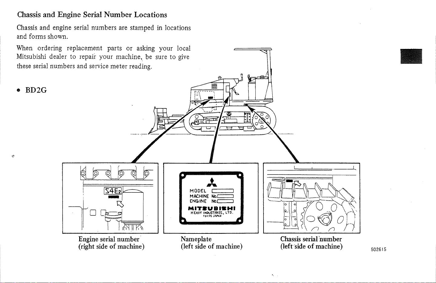
Chassis
and
Engine Serial
Number
Locations
Chassis and engine serial numbers are stamped in locations
and forms shown.
When ordering replacement parts or asking your local
Mitsubishi dealer
to
repair
your
machine, be sure
to
give
these serial numbers and service meter reading .
• BD2G
Engine serial number
(right side
of
machine)
~
MODEL I 1
MACHINE
ENG
MIT.UBISHI
HEAVY
Nameplate
(left side
No.c:::::::J
INE
No.c:::::::J
INDuSTRIES,
rCK"t1I
JAf'AH
of
LTD.
machine)
___
.!::==::!:=:==---L
Chassis serial 'number
(left-side
'.
of
machine)
502615
Page 3
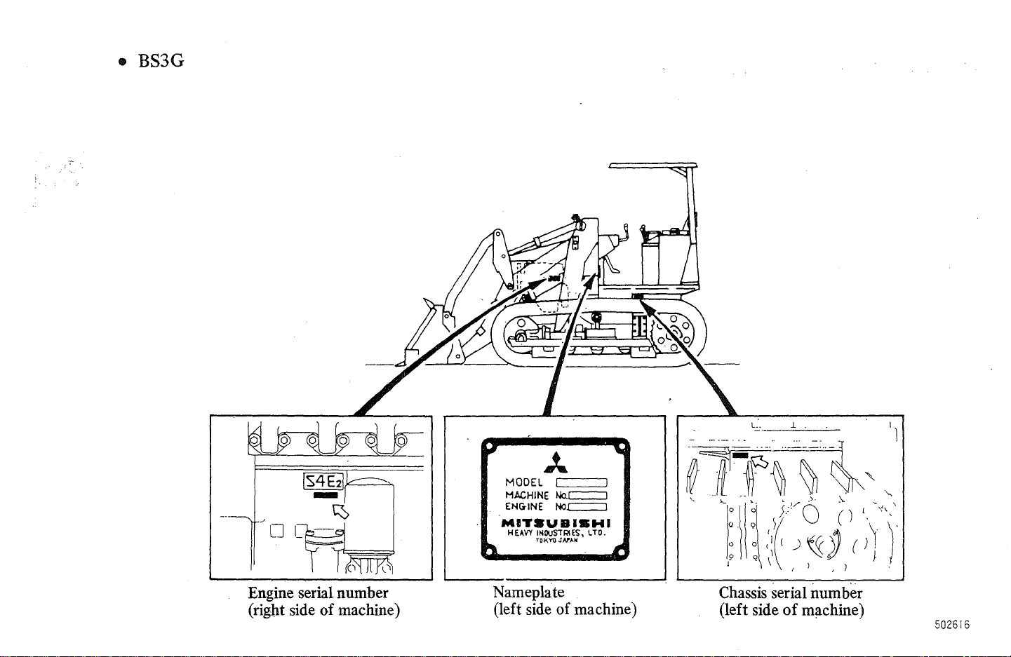
• BS3G
o
J...
MODEL I I
MACHINE
ENG
MIT.UBIBWI
HEAVY INDUSTRIES, LTD.
No.c::::::J
IN
E No.c::::=:::J
TOKYO
JAn.No
Engine serial number
of
(right side
machine)
Nameplate
(left side
of
machine)
Chassis serial number
(left side
of
machine)
502616
Page 4
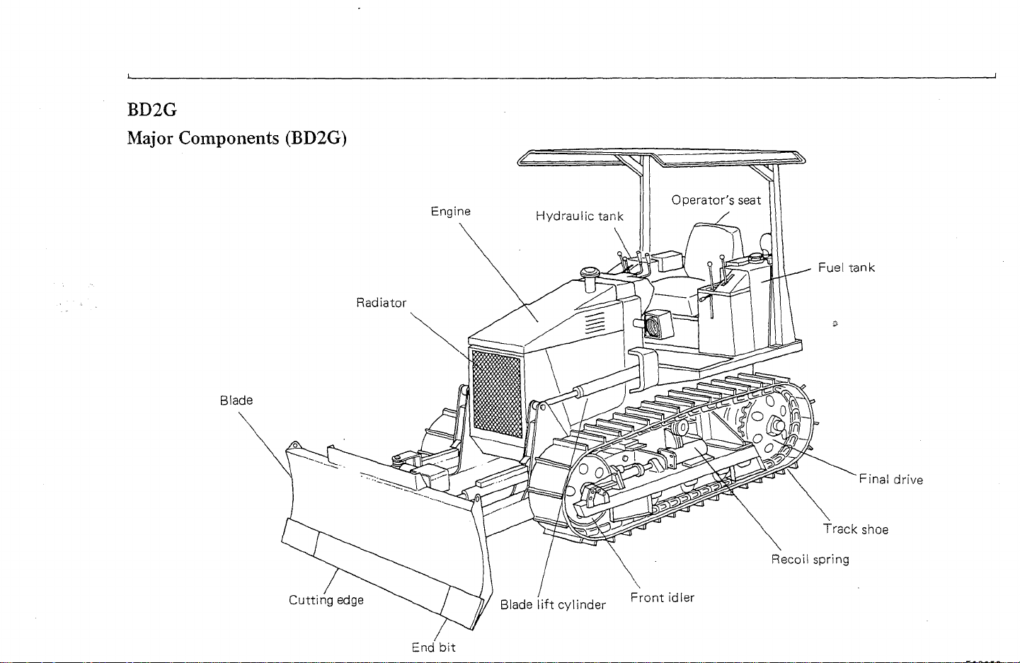
BD2G
Major
Components (BD2G)
Blade
Radiator
Engine
Fuel
Track
tank
Final drive
shoe
Cutting
edge
bit
Front
Recoil spring
idler
Page 5
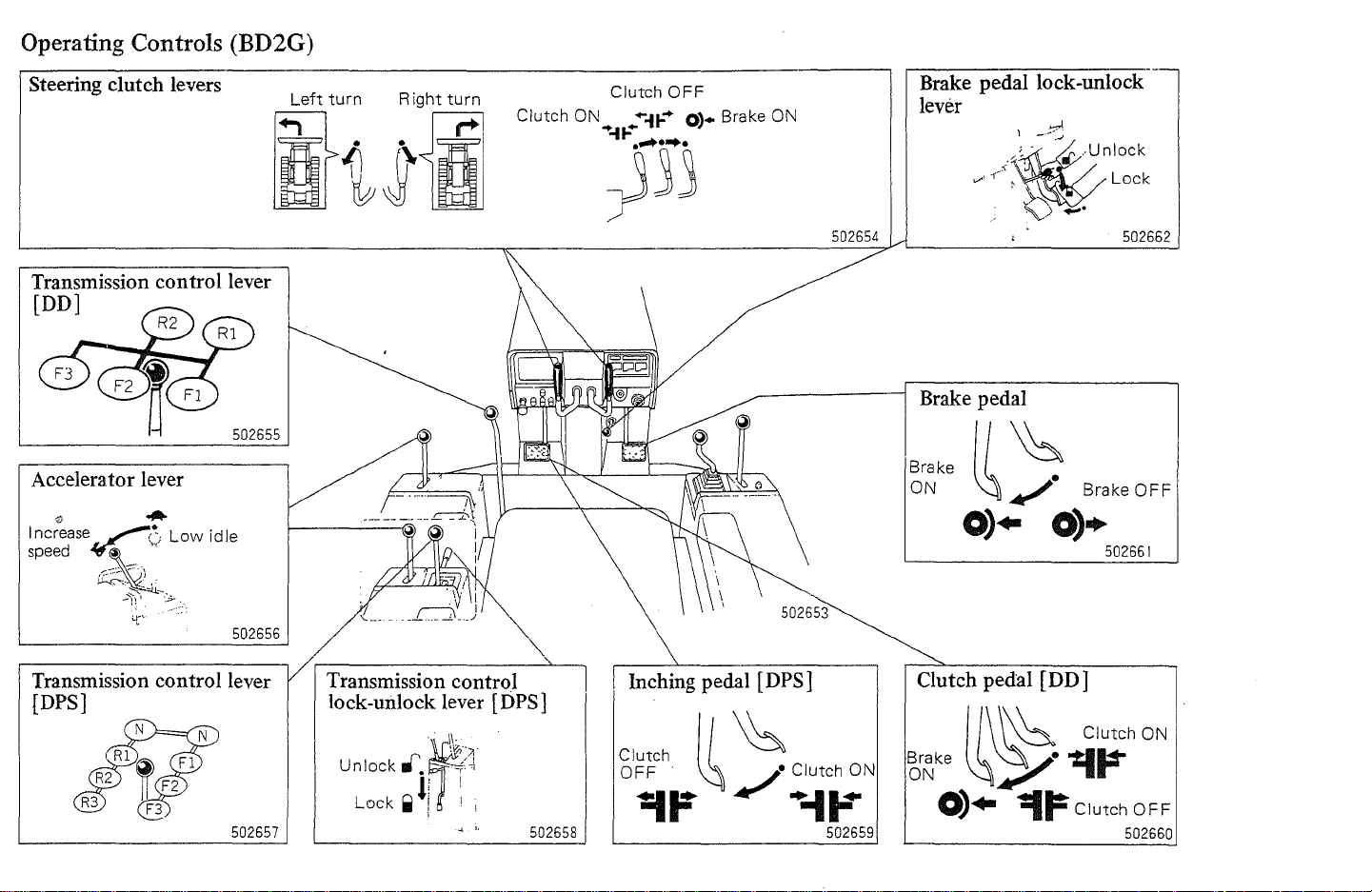
Operating Controls (BD2G)
Steering
Transmission
[DO]
Accelerator
clutch
levers
control lever
lever
Left
turn
Right
turn
Clutch ON
it~\i
502655
502656
Clutch
......
)33
....
n-
~..
OFF
....
0'.
'I
Brake ON
502654
Brake
lever
Brake
Brake
ON
pedal lock-unlock
pedal
~~
0)"
At'
~.
0)+
Brake
502662
OFF
502661
Transmission
{DPS]
control lever
502657
Transmission
lock-unlock
..
Unlock
rtf.~~~}
li
Lock
..
! ! I
;
control
lever
\\.
1
"
..
[DPS]
502658
Inching
Clutch II
OFF
.
pedal
~
~F
[DPS]
~
j.
Clutch ON
.,
+-11-"
502659
Clutch
~~ke
pedal [DO]
1/\
\h
Clutch ON
~~.~~
0)"
-=I~
Clutch
OFF
502660
Page 6
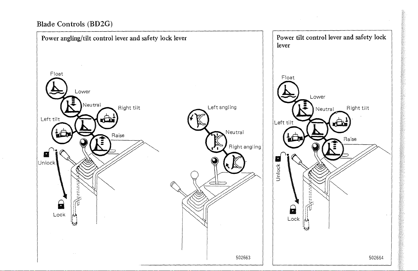
Blade Controls (BD2G)
Power angling/tilt control lever and safety lock lever
Float
Power tilt control lever and safety lock
lever
Float
502663
502664
Page 7

Indicators, Gauges and Switches (BD2G)
OK
monitor test switch
.. When this switch
with starter switch
Alternator
and engine oil pressure
warning lamps glow (with
engine stopped).
Ba
ttery
and air cleaner element
warning lamps glow (with
engine running).
electrolyte level
not
is
charging
pushed
ON:
Water
$
Normal
(green)
temperature
gauge Overheat
.--
______
TEMP
(red) .
50
1889
Service meter
hour
1
Every 6 minutes
dial advances
one number.
501887
OK
monitor
..
When any lamp glows
during operation, stop
machine soon and check
for cause. (See page 16.)
Battery switch
@i·.L-.---"------<.J
-§o-
Lighting
~I"
switch
Twist
~
1st 2nd
position
position
501959
502666
Position
Head
lamps
Working
lamp
Instrument
panel lamp
rop)
1st
Twist
2nd
'Twist
00
502665
Glow plug indicator
Glows when starter switch
turned to HEAT.
I Fuel gauge
Full
or
key.
engine.
(green)
501888
pull
501956
Empty
(red)
(l)
is
I
Starter switch
START
HEAT
OFF
ON
START
Heat engine.
I nsert
out
Keep engine
running.
Start
Page 8
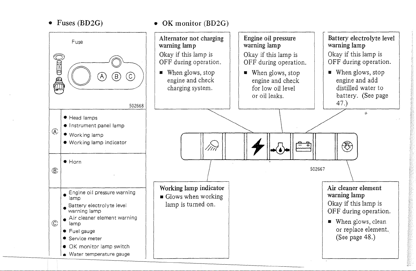
• Fuses (BD2G)
•
OK
monitor
(BD2G)
Fuse
• Head lamps
• I
nstrument
®
•
Working
•
Working
•
Horn
• Engine
lamp
•
Battery
warning lamp
•
Air
© lamp
• Fuel gauge
• Service
•
OK
III
Water
502668
panel lamp
lamp
lamp
indicator
oil
pressure warning
electrolyte
cleaner element warning
meter
monitor
temperature
lamp
level
switch
gauge
Alternator
warning lam p
Okay if this lamp
OFF during operation.
• When glows, stop
engine and check
charging system.
,--------------L-----
Working lamp indicator
• Glows when working
lamp
not
is
turned on.
charging
is
7
Engine oil pressure
warning lamp
Okay if this lamp
OFF during operation.
• When glows, stop
engine and check
for low oil level
or oil leaks.
1
is
\ /
502667
Battery electrolyte level
warning lamp
Okay
if
this lamp
OFF during operation.
• When glows, stop
engine and add
distilled water
battery. (See page
is
to
47.)
\
Air cleaner element
warning lamp
Okay
if
this lamp
OFF
during operation.
• When glows, clean
or replace element.
(See page 48.)
is
Page 9
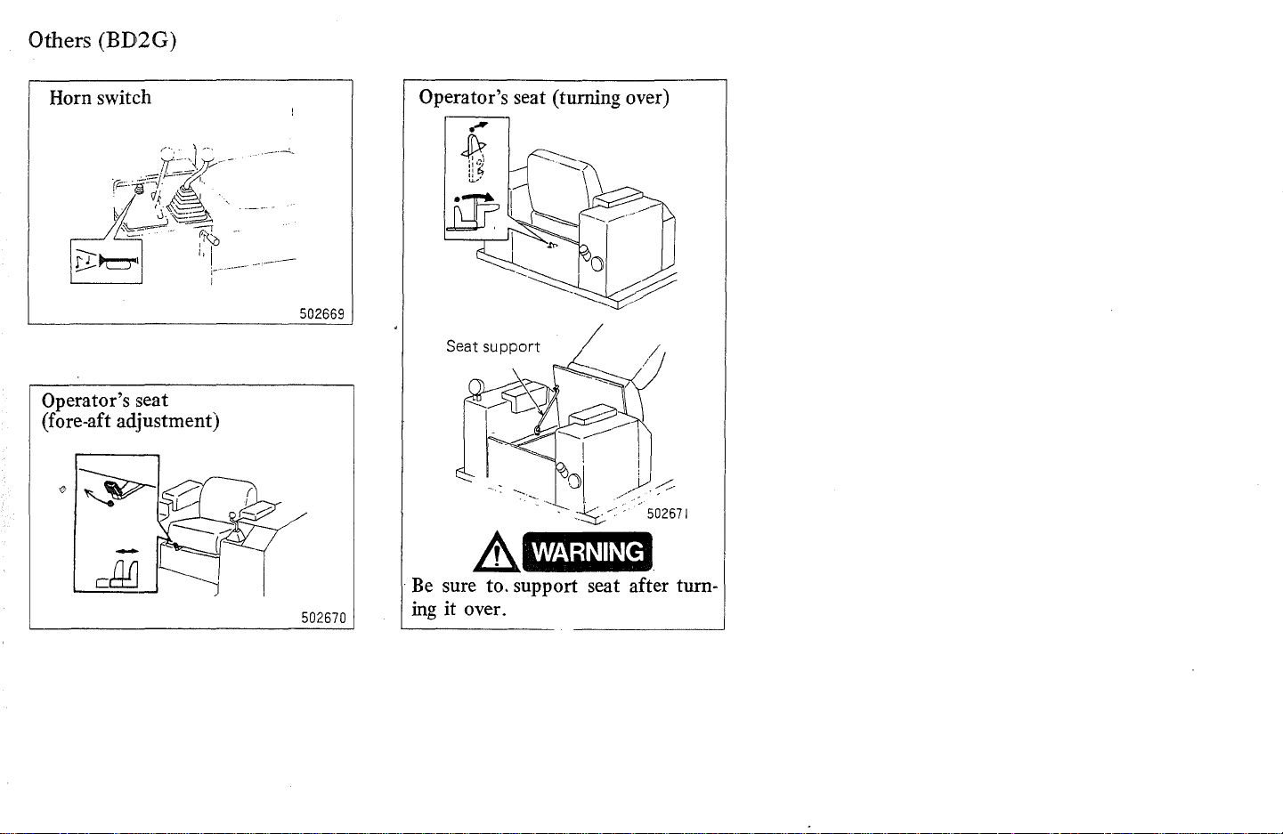
Others (BD2G)
Horn
switch
Operator's seat
(fore-aft adjustment)
502669
502670
Operator's seat (turning over)
.-
1:1
lL~
iJF
'------,--'
Seat support
A
. Be sure to. support seat after turn-
ing it over.
---.::::.?\
\ \
1---
~
l~//--
I
WARNING
Page 10
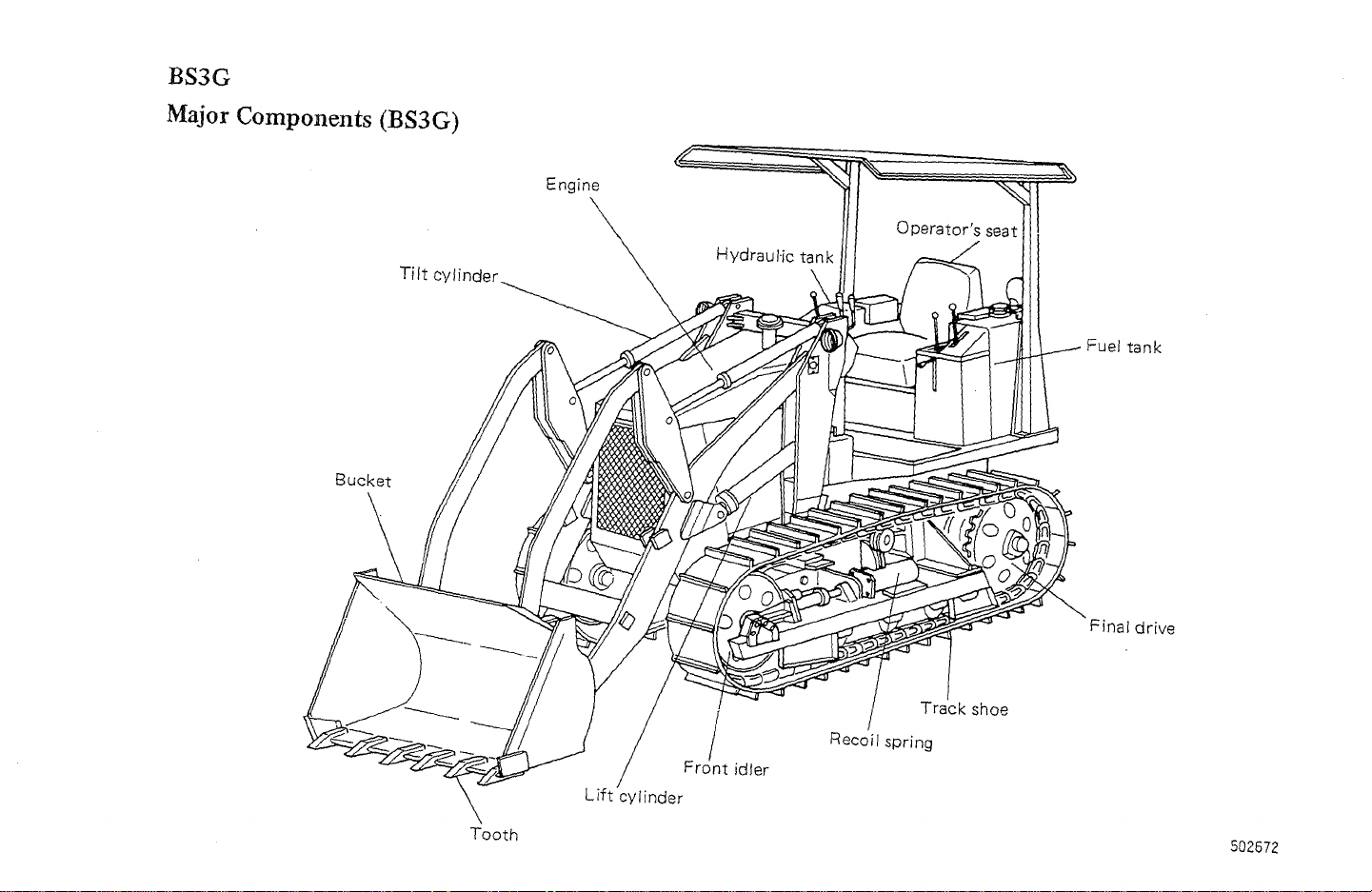
BS3G
Major Components (BS3G)
Tilt cylinder
Bucket
Engine
Fuel
Final
tank
drive
Tooth
Track
shoe
502672
Page 11
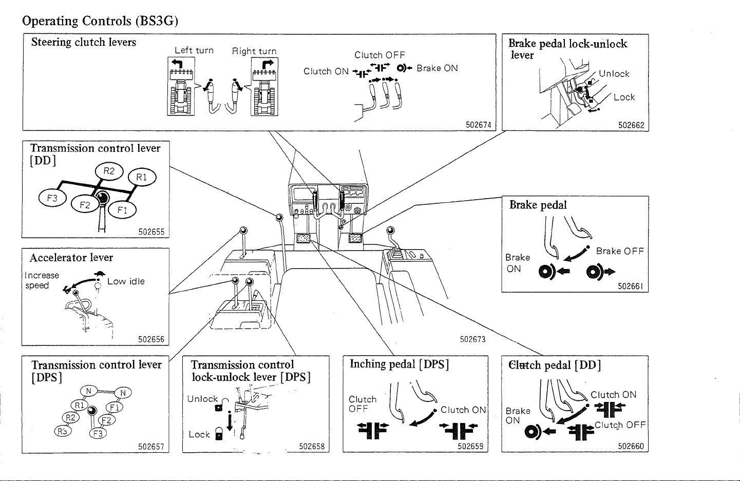
Operating Controls (BS3G)
Steering
Transmission
(DD]
Accelerator
clutch
lever
levers
control lever
502655
502656
Clutch ON
Clutch
.....
t-
.....
it-
OFF
..
0)·
Brake ON
~'Ij
502674
Brake
lever
Brake
Brake
ON
pedal lock-unlock
Lock
502662
pedal
II
~
8rnk'
OFF
~..,
0).
o~
502661
Transmission
(DPS]
control lever
502657
Transmission
lock-unlock
unIOc~.~
Lock
..
l;
control
lever
\-.
r\'
:;:~--.
-'
j
[DPS]
502658
Inching
Clutch
O~F
pedal
[DPS]
·11
'~
~/~-I;~N
502659
Elmch
Brake .
ON
~
0).
pedal
[D D ]
\
~
~'0$.../.
~~
Clutch
'=I~
lIt=Clutc,h
ON
OFF
502660
Page 12
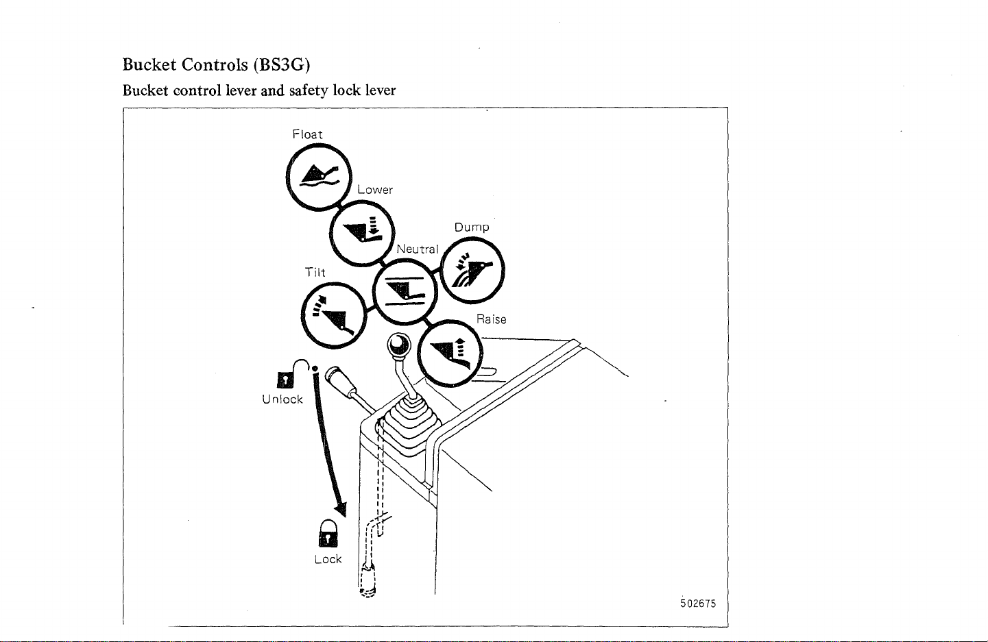
Bucket Controls (BS3G)
Bucket control lever and safety lock lever
Float
502675
Page 13
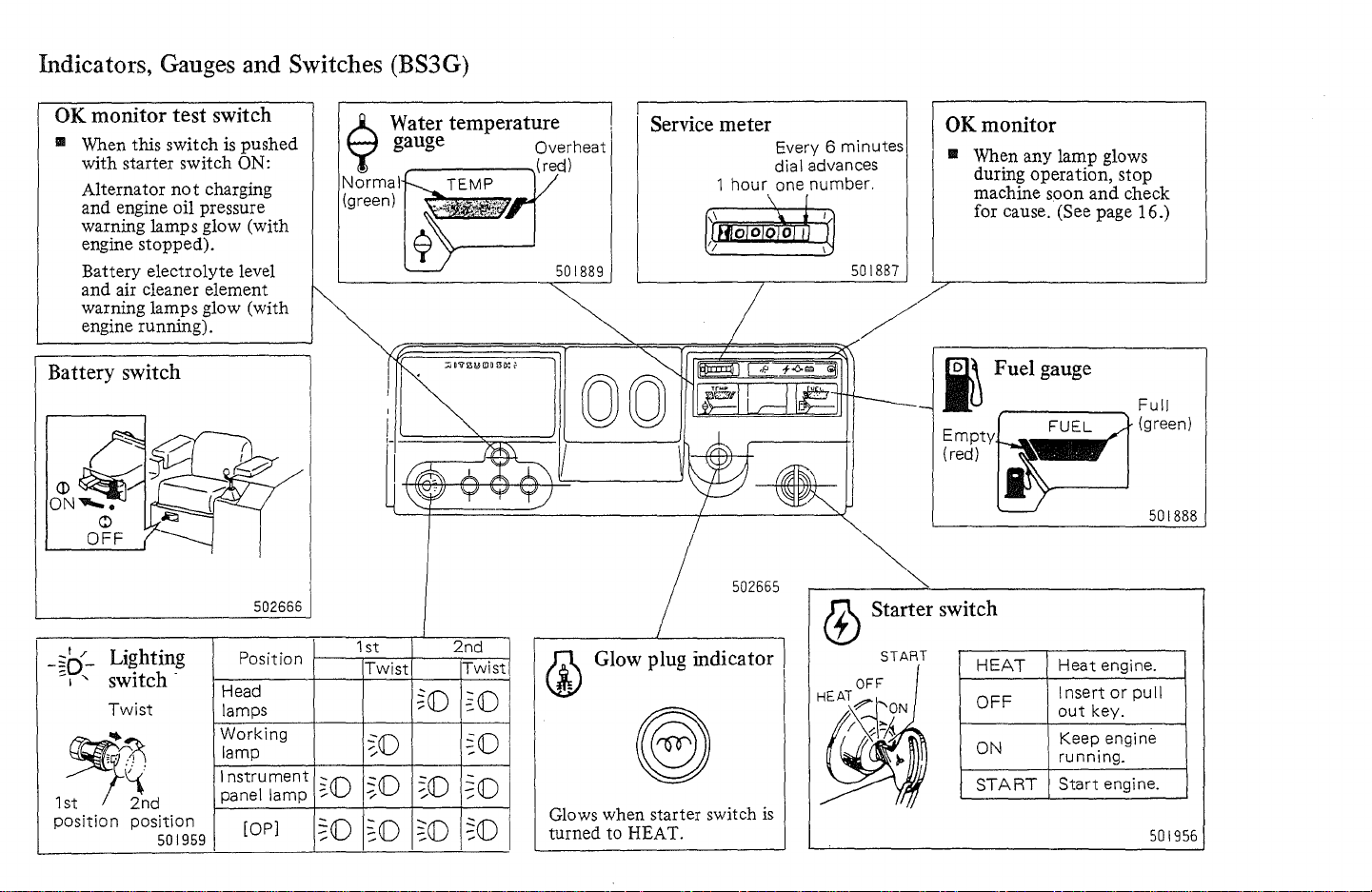
Indicators, Gauges and Switches (BS3G)
OK monitor
III When this switch
with starter switch
Alternator
and engine oil pressure
warning lamps glow (with
engine stopped).
Battery electrolyte level
and air cleaner element
warning lamps glow (with
engine running).
test
not
charging
Battery switch
_I
/
-~D-
Lighting
-I
"
switch -
Twist
~
1st
position
2nd
position
501959
switch
is
pushed
ON:
502666
Position
Head
lamps
Working
lamp
Instrument
panel lamp
lOP]
6 Water temperature ,
);
gauge Overheat
Norma
(green)
1 st
Twist
~(j)
~(j)
~(j)
,-
~(j)
~O
TEMP
2nd
Twist
~(j)
~O
~O
~(j)
~O
~(j)
~(j)
Service meter
1
hour
501889
502665
Glow plug indicator
Glows when starter switch
turned to HEAT.
Every 6 minutes
dial advances
one number.
501881
(j)
is
OK
monitor
III When any lamp glows
during operation, stop
machine soon
for cause. (See page 16.)
i Fuel gauge
Empty
(red)
Starter switch
START
HEAT
OFF
ON
START
and
check
Full
(green)
Heat
engine.
Insert
or
out
Keep engine
running.
Start
pull
key.
engine.
501888
501956
Page 14
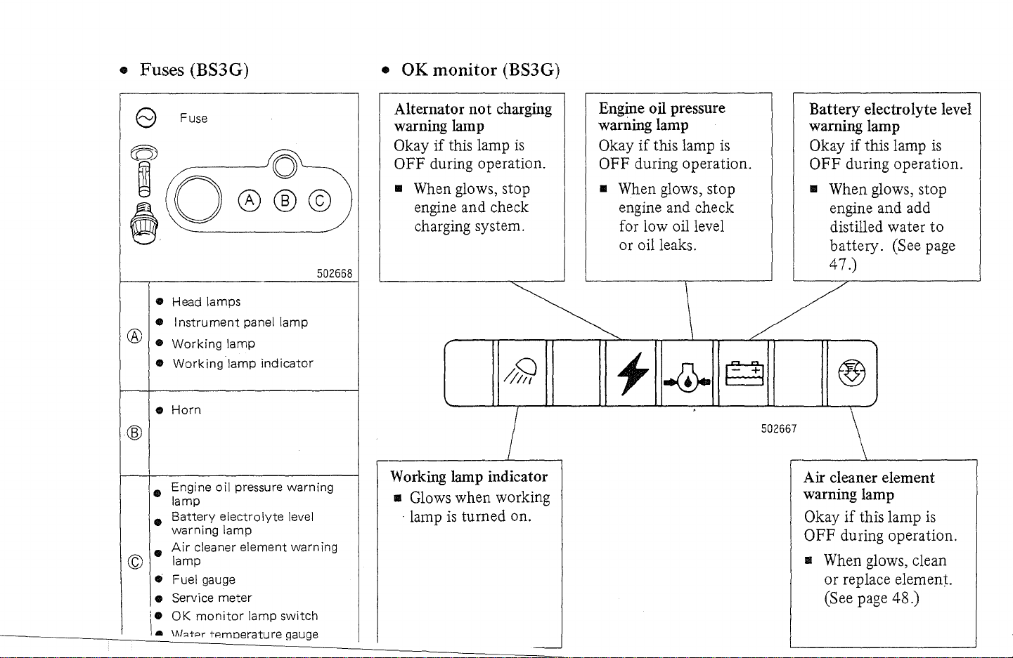
• Fuses (BS3
G)
•
OK
monitor (BS3G)
e Fuse
(Ql~
&0
• Head lamps
• I
nstrument
® •
© lamp
Working
•
Working
•
Horn
• Engine
lamp
•
Battery
warning
•
Air
cleaner element warning
• Fuel gauge
• Service
i.
OK
\.
IAbtpr
@@©)
panel
lamp
lamp
oil
pressure warning
electrolyte
lamp
meter
monitor
lamp
tAmoerature gauge
lamp
indicator
level
switch
502668
Alternator not
warning
Okay
OFF during operation.
.. When glows, stop
lamp
if
this lamp
engine and check
charging system.
charging
is
I
Working
II
. lamp
lamp
indicator
Glows when working
is
turned on.
Engine oil
warning
Okay
OFF during operation.
.. When glows, stop
engine and check
for low oil level
or oil leaks.
pressure
lamp
if
this lamp
is
Battery electrolyte level
warning
Okay if this lamp
OFF during operation.
II
lamp
is
When glows, stop
engine and add
distilled water
battery. (See page
47.)
to
\ /
f
502667
\
Air
cleaner element
warning
Okay
OFF during operation.
II
-
lamp
if
this lamp
When glows, clean
or
replace element.
(See page 48.)
is
Page 15
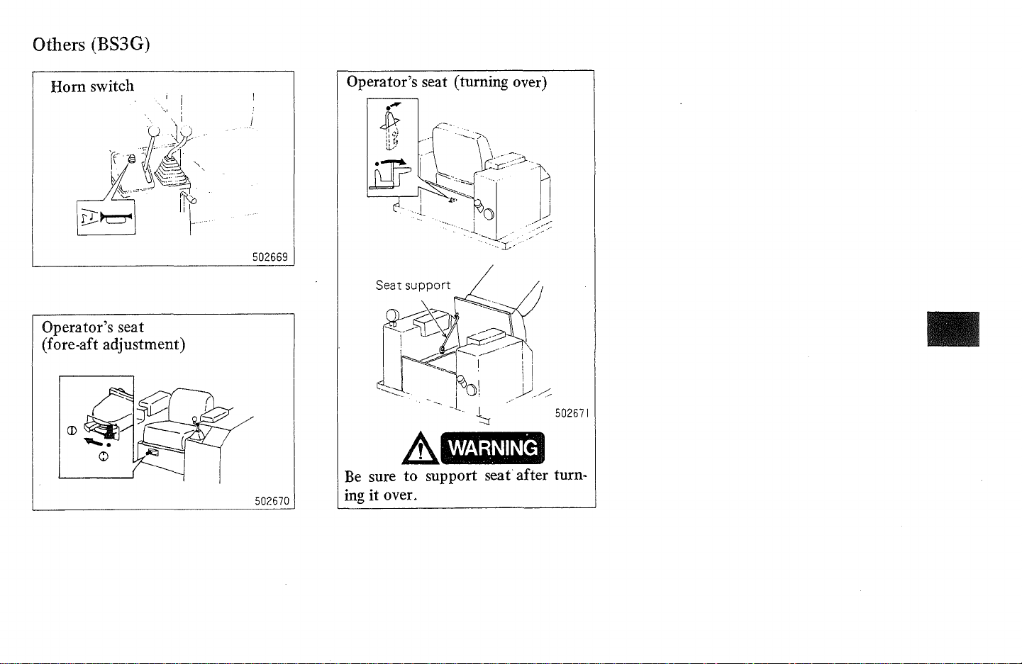
Others (BS3G)
Horn switch
Operator's seat
(fore-aft adjustment)
L-
____________________
I I
".,1
Operator's seat (turning over)
:
502669
WARNING
Be
502670
~~
sure to support
ing
it
L-
over.
______________________
seat
after turn-
__
Page 16
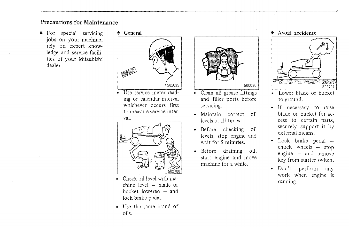
Precautions for Maintenance
..
For
special servlcmg
on
your
jobs
rely
on
machine,
expert
ledge and service facili-
of
your
ties
Mitsubishi
dealer.
know-
• General
502699
• Use service meter reading or calendar interval
whichever occurs first
to measure service interval.
• Check oil level with
machine level - blade or
bucket lowered - and
lock brake pedal.
I
• Clean all grease fittings
and filler ports before
servicing.
• Maintain correct oil
levels
at
all times.
• Before checking oil
levels, stop engine and
wai t for
5 minutes.
• Before draining oil,
start engine and move
machine for a while.
500020
• Avoid accidents
50270
• Lower blade
or
bucket
to ground.
•
If
necessary to raise
or
blade
bucket
for ac-
cess to certain parts,
securely
support
it
external means.
• Lock brake pedal chock wheels - stop
engine - and remove
key from starter switch.
•
Don't
work
perform any
when
engine
running.
I
by
is
• Use the same brand
oils.
of
Page 17
502702
502703
500022
500024
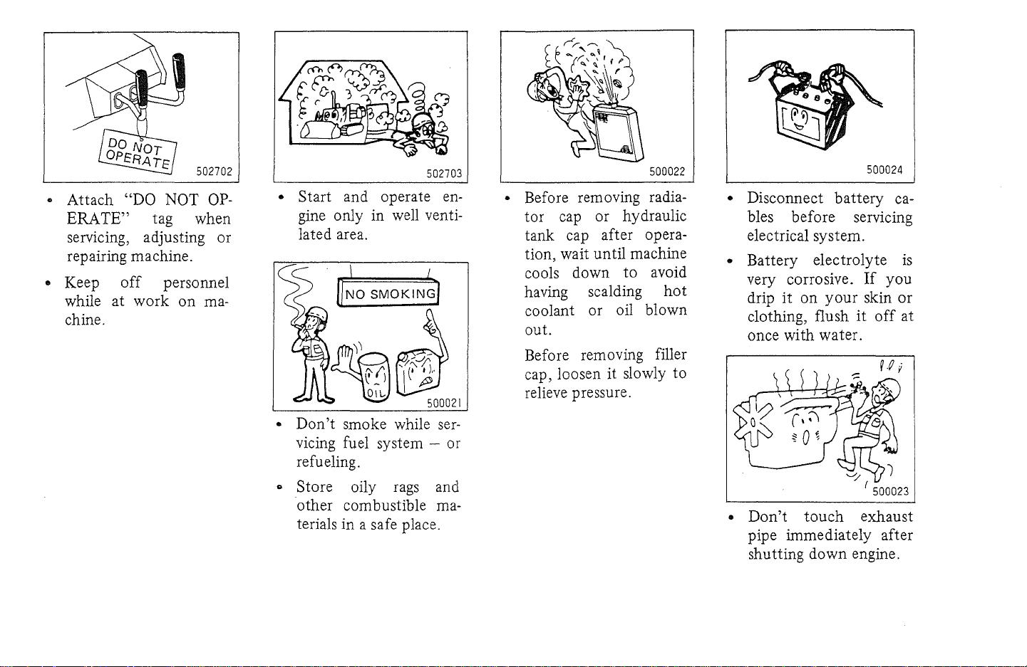
•
Attach
ERA
"DO NOT
TE"
tag when
servicing, adjusting or
repairing machine.
• Keep
while at
off
work
personnel
on
chine.
OP-
ma-
• Start and operate engine only in well ventilated area.
•
Don't
smoke while
servicing fuel system - or
refueling.
o Store oily rags and
other combustible materials in a safe place.
• Before removing radiator
cap or hydraulic
tank cap after operation, wait until machine
to
cools down
having scalding
avoid
hot
coolant or oil blown
out.
Before removing filler
cap, loosen
it
slowly to
relieve pressure.
• Disconnect
battery
bles before servicing
electrical system.
• Battery electrolyte
very corrosive.
drip
it
on
clothing, flush
your
If
skin
it
off
once with water.
•
Don't
touch
exhaust
pipe immediately after
shutting down engine.
ca-
is
you
or
at
Page 18
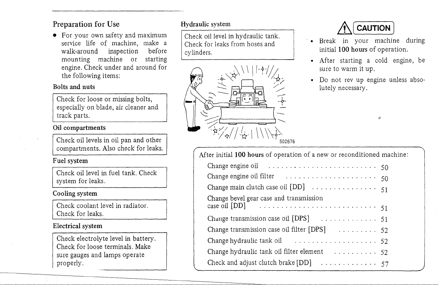
Preparation for Use
• For
Bolts and nuts
your
own safety and maximum
of
service life
walk-around inspection before
mounting machine or starting
engine. Check under and around for
the following items:
machine, make a
Hydraulic system
Check oil level in hydraulic tank .
Check for leaks from hoses and
cylinders.
~(
• Break in your machine during
initiallOO hours
• After starting a cold engine, be
sure to warm it up.
•
Do
not
lutely necessary.
CAUTION)
rev
up
engine unless abso-
of
operation.
Check for loose or missing bolts,
especially
track parts.
Oil compartments
Check oil levels in oil pan and other
compartments. Also check for leaks.
Fuel system
Check oil level in fuel tank. Check
system for leaks.
Cooling system
Check coolant level in radiator.
Check for leaks.
Electrical system
Check electrolyte level in battery.
Check for loose terminals. Make
sure gauges and lamps operate
properly.
on
blade, air cleaner and
---
>==;~~~:::L.,
\\
After
initialI00
Change engine oil
Change engine oil filter . . . . . . . . . . . . . . . . . . . 50
Change main clutch case oil [DD]
Change bevel gear case and transmission
case
oil [DD] . . . . . . . . . . . . . . . . . . . . . . . . .
ChaIlge transmission case oil [DPS]
Change transmission case oil filter [DPS]
Change hydraulic tank oil . . . . . . . . . . . . . . . . .
Change hydraulic tank oil filter element
Check and adjust clutch brake [DD]
hours
-~.
I
\\~
I 502676
of
operation
......
of
. . . . . . . . . . . . . . . . .
a new or reconditioned machine:
...............
..........
.......
..........
.............
.
..
50
51
..
51
..
51
" 52
..
52
52
57
Page 19
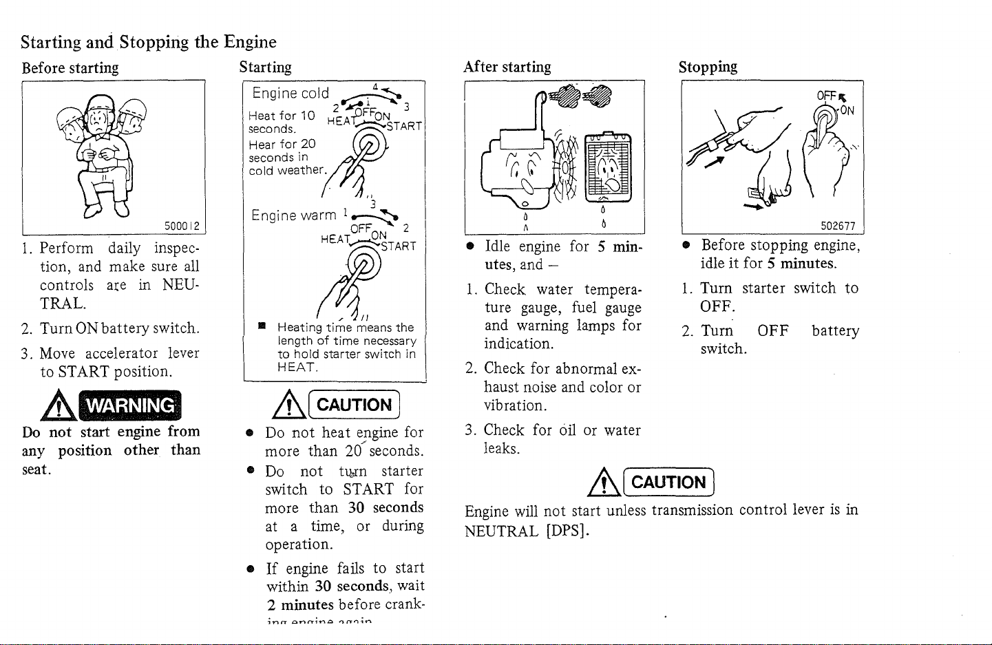
Starting and Stopping the Engine
Before starting
500012
1.
Perform daily inspec-
tion, and make sure all
a:ce
controls
in NEU-
TRAL.
2.
Turn ON battery switch.
3. Move accelerator lever
to START position.
A
Do
any position other
WARNING·
not
start engine from
than
seat.
Starting
Engine cold
Heat
for
10
seconds.
Hear
for
seconds
cold
Engine
20
in
weather.
warm
~
2"-~1
HEAfFFON
;t~START
1
~
OFF
l:START
..
Heating
length
to
HEAT.
&,,(
• Do
more than
•
Do
switch to START for
more than
at a time, or during
operation.
time
of
time
hold
starter
CAUTION)
not
heat engine for
20/ seconds.
not
tl¥n
30 seconds
means
... 3
'3
2
ON
the
necessary
switch
in
starter
After starting
• Idle engine for 5 minutes,
and-
1.
Check water tempera-
ture gauge, fuel gauge
and warning lamps for
indication.
2.
Check for abnormal
ex-
Stopping
• Before stopping engine,
it
idle
1.
Turn starter switch to
for 5 minutes.
OFF.
2.
Turn
OFF
switch.
haust noise and color or
vibration.
oil
3. Check for
or water
leaks.
&,,(
CAUTION)
Engine will not start unless transmission control lever
NEUTRAL
[DPS].
502677
battery
is
in
•
If
engine fails to start
within
30 seconds, wait
2 minutes before crank-
Page 20
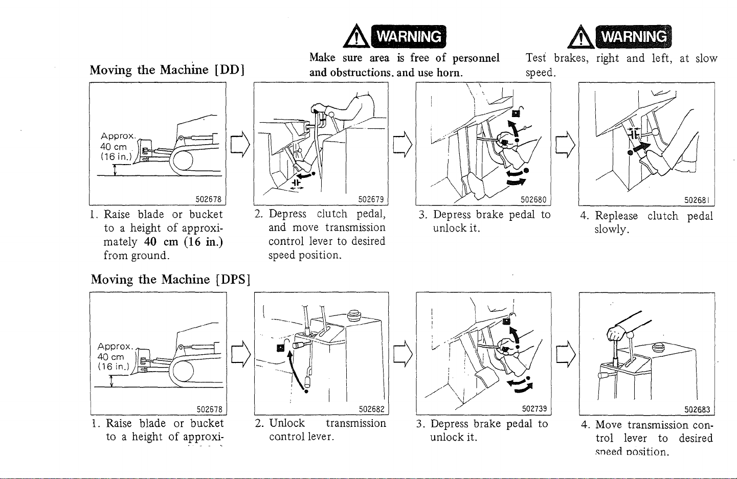
Moving the Machine [D D ]
WARNING
Make
and obstructions. and use horn.
sure
area
is
free
of
personnel
.&
Test brakes, right
speed.
and
left,
at
slow
502678
1.
Raise blade
to
a height
mately
from ground.
40
or
of
em
bucket
approxi-
(16
in.)
Moving the Machine [DPS]
502678
1.
Raise blade
to
a height
or
of
approxi-
bucket
502679
2.
Depress clutch pedal,
and move transmission
control lever to desired
speed position.
502682
2. Unlock transmission
control lever.
3.
Depress brake pedal to
unlock it.
j . I
/--\.
i
./
3. Depress brake pedal
unlock
,.
)V
/'
it.
./
502739
to
4. Replease
slowly.
clutch
If!
4.
Move transmission control lever
."need Dosition.
to
502681
pedal
502683
desired
Page 21

WARNING
WARNING
LtJ
CAUTION)
Avoid sharp starts, stops or turns
whenever possible for your own safety,
for maximum service life
machine.
Steering
• Right
or
left turns
.,
of
r+
your
• •
fi
Loft
tom
L-
________________________
t1
Righttum
fi fi
__
502684
A void sidehill travel whenever possible.
Drive up and down a slope. The danger
of
tipping is always present. Sidehill
travel can also cause uneven wear
track parts.
• Moderate
~
Moderate
turns
or
sharp turns
Steering
clutch
OFF
Steering
clutch
brake
'--11-"
0)·
.-'j-h
j
j_
ON
r-------,
~~
ii
Sharp
turns
of
502685
When shifting
clutch pedal
clutch brake, and try again [DD].
&J
Do
not
drive your machine with your
foot resting on clutch or brake pedal.
&[
Avoid sharp turns, especially
speeds.
wear
case, cause track
Such turns cause premature
of
track parts and,
is
difficult, depress
all
the way
CAUTION)
CAUTION)
to
get
out
in
the
of
to
apply
at
worst
place.
high
1.
To make moderate turns, pull steering clutch lever slowly and accordingly.
2. To make sharp turns, pull steering
clutch lever quickly
all
the way.
Page 22

"
Changing Speed or Direction [DD]
1.
Reduce machine speed
by
moving accelerator
lever back, and depress
clutch pedal.
Stop
Move
and
change speed
2, Depress brake pedal,
and move transmission
control lever to desired
position.
Move
502686
Changing Speed or Direction [DPS]
• It
Move transmission con-
trollever
to desired
postion.
is
depress inching pedal.
not
necessary to
Move
forward
3. Release clutch pedal to
start your machine moving again.
Stop
and Move
change
direction
backward
• When changing direction, be sure to come
to a complete stop
avoid damage
to
trans-
mission.
502687
to
Lt(
CAUTION)
• When changing speed or
be
sure
direction,
to
come to a complete stop
by depressing brake
pedal to avoid damage
to transmission.
• When shifting
is
difficult, depress clutch
pedal all the way
to
apply clutch brake, and
try
again
[DD]
.
Page 23

~topping
1. Reduce machine
speed by moving
accelerator lever back
back.
l D D 1
Stopping [DPS]
1.
Reduce machine
speed by moving
accelerator lever back.
2. Depress clutch pedal
and, at the same
time, -
2.
Move
transmission
control lever to
NEUTRAL
3.
Depress brake pedal
gently to stop your
machine.
3. Depress brake pedal
gently to stop your
machine.
4.
Move
transmission
control lever to
NEUTRAL, and
release clutch pedal.
WARNING
When leaving your machine unattended, be sure to:
1. Lower blade or bucket to ground. Lock blade control
lever with safety lock lever on machine equipped
with power angling-tilt control.
2. Make sure transmission control lever
On
DPS
machine, lock transmission control with
lock-unlock lever.
3. Lock brake pedal.
4.
Shut
off
engine, and remove key from starter switch.
5.
Turn OFF battery switch.
is
in NEUTRAL.
WARNING
When
right angles to the slope - chock tracks - and penetrate
blade into ground.
parking your machine on a slope, position
it
at
Page 24

Operating Techniques
• Going up slopes
• Going down slopes
• Going over obstacles
502635
•
Drive
Sidehill travel can cause machine to
slip
•
Do
effect becomes more effective than
when on level surfaces.
• Shifting on slopes
• When shifting on a slope, depress
brake pedal to stop machine,
press clutch pedal and move transmission control lever to desired
position.
too late, shifting would
In such a case, move machine
ward just a little and try again.
up
as
straight
sideways or track to slip off.
not make quick turns. Steering
If
clutch pedal
as
possible.
is
depressed
be
difficult.
de-
for-
502689
• In steep downhill operation,
allow engine to overspeed. Select
proper speed before starting
chine downgrade.
• Steering controls sometimes reverse
is
when machine
or being pushed by a load.
steering clutch
way, for instance, .machine would
make a right turn.
~
Never
TRAL. Always stay in gear .
free wheel downgrade in
WARNING
coasting downhill '
lever
is
do
not
ma-
If
left
pulled half-
NEU-
Alert
for
jolt
502690
•
Go
over an obstacle with extreme
an
angle
care at
machine speed, and ease up to
"breakover".point - balance slowly
on an obstacle
the other side, being alert for jolt
of contact.
~
Do
not exceed maximum limit
chine stability indicated on nameplate
attached to machine.
if possible. Reduce
- .and ease down to
WARNING
of
ma-
Page 25

• Operating in deep
mud
or
water
• Operating in
rocky
terrain
•
Super
swamp
swamp models
and
ultra
super
• Drive
Avoid sharp
..
Make sure drain plugs
compartments
..
When starting
do
saw"
by
tion
your
machine at low speeds.
or
frequent
are tight in place.
to
mire
down
not
spin
your
track
machine.
or
dropping load, changing direc-
or
placing planks
for recovery.
..
Check oil in final. drives for
of
mud
or
water
with new oil
foreign
matter
more
upon
in oil.
502691
turns.
of
all gear
in
try
to
Get
traction
under
tracks
entry
often.
Refill
discovery
mud,
"see-
of
• On rocky footing,
track
parts are
subject to excessive stress and strain.
When operating in such a terrain,
loosen
4
track
to
6 em (1-1/2
Refer to page
track
adjustment.
• Operating
adjustment to obtain
to
2-3/8
54
of
this manual for
on
snow
in.) sag.
• Use snow-and-ice shoes whenever
possible. These shoes are designed
for good
penetration
and
traction
on ice or hard packed snow.
•
At
end
of
operating period, clean
or
mud
from
snow
around
track
links, sprockets, idlers, rollers and
to
guards
orevent freezin!:!
of
trllch
..
Track shoes
of
are designed for use
areas. Avoid operating
in
rocky
hard
damage
terrain
surfaces
to
the
shoes.
the
swamp
only
or
going over rough,
to
prevent
in
these
models
swampy
models
costly
Page 26

• Stripping or leveling
A[
When stripping or leveling by driving
machine forward, do
fully; otherwise bucket, bucket linkage
and frame would suffer costly damage.
• When moving one job site to
other, be sure to lock bucket
control lever to avoid accidents.
CAUTION)
not
dump bucket
an-
Page 27

Transporting
JIll
Check regulations covering transportation
ment
including tractors.
Loading
the
Machine
of
construction equip-
4
..
Drive up machine forward when
loading. Drive it backward when
unloading.
5.
Be
sure
to
block truck wheels.
1.
Loading platform
than overall width
thoroughly compacted along its
length.
If
loading platform
2.
use ramps. Ramps must be strong
enough to load machine safely.
Support each ramp
from underside to prevent it from
being weighed down
3.
Platform or ramps
gradient
of
10
to
15 deg.
must
of
is
be wider
machine and
not
available,
with
by
machine.
must
have a
blocks
&.(
Drive up and down without steering.
If
machine starts slipping sideways,
drive it down to ground immediately,
and try again.
6.
Upon loading, block tracks on
front and rear sides, and secure
machine with tie-downs such
chains or ropes to prevent side slip.
7. Lower blade or bucket, lock brake
pedal, and place all controls in
NEUTRAL.
8. Plan travel route by checking state
and local laws, weight limits,
pass clearance, etc.
CAUTION)
both
as
over-
Page 28

Special Conditions
Operating
• Lubricants
in
cold weather
and
diesel fuels
• Coolant
Engine cooling system
•
machine shipped from factory
filled with coolant containing 30%
of
Mitsubishi Long Life Coolant
(antifreeze containing rust inhibitor).
of
a new
is
• Long Life Coolant is highly flammable; keep
flame.
• Starting in cold
it
away
weather
from
open
• Use lube oils
See
the
FUELS AND LUBRICATNS, in
page 59.
• Use diesel fuels having lower
point.
MENDED FUELS AND LUBru-
CANTS, in page 59.
• Battery
• Add distilled water to
fore starting engine for the day's
run.
• Always keep
so
is
20°C
See
that
electrolyte specific gravity
higher
than
(68°F).
of
lower viscosity.
chart, RECOMMENDED
the
chart, RECOM-
battery
battery
1.28
fully charged
as
corrected
pour
be-
to
• Long Life Coolant
sub-zero temperatures down
-ISoC (SOF).
When using Long Life Coolant
•
temperatures below -ISOC
rely
on
the following chart for
correct percentage.
Starting
temperature
°c
(OF)
Percentage
of
Long Life
Coolant
• Change Long Life Coolant every
2 years. When changing, flush cooling system thoroughly.
• Use Long Life Coolant
water.
~
• Long Life Coolant is poisonous;
be careful
drip
it
on
-20
(-4)
35
WARNING·
not
your
is
effective for
-30
(-22) (-40)
45
with
to
drink it.
skin, flush it
(SOF),
-40
55
soft
If
you
o,ff
to
at
at
•
Turn
starter switch
tion
to
heat
After starting engine, warm it up
thoroughly.
•
After
operating
• Clean snow or
your
machine
on
Park
or logs
• Wipe dirt
rods
• Drain
tank.
dry concrete floor, planks
to
avoid freezing.
and
of
hydraulic cylinders.
water
and sediment from fuel
to
HEAT posi-
engine thoroughly.
in
cold
weather
mud
from around
to
prevent freeZing.
moisture from piston
Page 29

vpt:raung
III
nor wearner
engine cool. Check radiator for low
coolant level, leaks or trash buildup.
502698
• Lubricants
Use lube oils
the chart,
of
higher viscosity. See
RECOMMENDED FUELS
AND LUBRICANTS, in page 59.
• Battery
Check electrolyte level more often
Add
than in cold weather.
water
to
batteries whenever level
distilled
is
low.
• Coolant
Engine
especially in heavy
hours
is
likely
or
in ascending a long, steep
to
get overheated,
duty
operation for
slope. Whenever water temperature
gauge registers near
slow down
or
or
in RED range,
stop machine, and let
• After operating
• Before stopping engine, let
just longer
in
hot
weather
than
in cold weather for
it
idle
cooling.
• Check coolant level in radiator and
electrolyte level in batteries.
Operating in extremely dusty
conditions
• Check air cleaner element and
change it more often.
• Clean air breathers
fuel
tank
to help prevent premature
wear
of
pistons and cylinders.
of
engine and
• Remove dust accumulated inside
alternator and starter covers. Clean
radiator core. Wash machine from
as
clean
time to time to keep it
as
possible.
Page 30

I\..t;;l:UHHW.::uueu r UeTh
auu
LUUnCanr
s
"
Refill
capacity
liter (U.S. gal)
60 (15.S)
7
(I.S)
5.5 (1.5)
3.5 (0.9)
9.5(2.5)
11
(2.9)
(l.S)
7
Each side:
6.S
(1.7)
*1
9.5 (2.5)
*2
13
(3.4)
33 (S.7)
13
(3.4)
.
,
Fuel
*
Engine
*
Main
Compartment
tank Diesel fuel
clutch [DD] Engine oil
. :
j'
:,)
ii'
t.,.,·.
,:.,:"
;.'
','
i'
,:'
i;
* Damper case [DPS] Engine oil
I"
* Transmission case
'.
".,
[DD]
{
},
* Transmission case
r:,'
[DPS]
I'.
* Transfer/bevel gear
case
[DPS]
I,
"
t'
* Final drive gear
cases
[.
~;.
i
* Hydraulic tank Engine oil
fi.
Grease
various
t:,
I:;,
Radiator
fi'
11'.
1""
I~
i:
I""
fittings on
points
Mitsubishi Toughness Multi engine oil can be used in compartments marked *.
*1: Super swamp
model
Lubricants,
Engine oil
etc
CD
CD
CD
Gear oil GL-4'
Engine oil
CD
Gear oil GL-4
Gear oil GL-4
CD
Grease
Soft water
*2: Ultra super swamp model
-25
(-13)
SAEIOW 0
SAE5Wf
NLGINo.O
Soft water with antifreeze
-15
(5)
I
SAE5W
SAE5W
SAE80
SAE5W
SAE 80
SAE80
~NLGINo.l#
Ambient
I
Consult
AE
207
L
£
£
temRerature
-5
(23) (32) (41)
0 5 '
°c
(oF)
I
your Mitsubishi dealer
,
,
SAE
SAE
SAE
lOW
SAE 30
lOW
lOW
SAE90
lOW
SAE 90
SAE 90
§
J
J
,
,
I
I
I
I
I
I
,
I
I
SAE
,
NLGINo.2
I
Soft
//
water
15
(59)
25
(77)
I
..
Page 31

Factory-Filled Lubricants
The following list shows brands
tractor shovels shipped from the factory:
Compartment Brand name
Engine
Main clutch case [DD]
Damper case [DPS]
Transmission case [DD]
Transmission case [DPS]
Transfer/bevel gear case
[DPS]
Final drive gear cases
Hydraulic tank SAE
of
lubricants used in Mitsubishi tractors and
SAE 30 (Diamond HD30 special)
SAE
lOW
(Diamond
lOW
SAE
SAE
SAE
.
SAE 90 (Apolloi! Gear HE90)
SAE
(Diamond
90
(Apolloi! Gear HE90)
lOW
(Diamond
90
(Apolloi! Gear HE90)
lOW
(Diamond HDIOWspecial)
(NOTE)
• These brands are subject to change without notice.
• Avoid mixing lubricants.
with each
brand
other
at
successive service intervals.
and deteriorate when mixed.
In
some cases, different brands
It
HD
S-3
lOW)
HD
S-3
lOW)
HD
S-3
lOW)
of
lubricants are
is
best to stick with one and the same
not
compatible
• Temperature range
of
Mitsubishi Toughness Multi engine oil is -20
to
40°C (-4
to
104°F).
Page 32

Inspection and charging
• Removal and installation
Removal
Installation
A battery
charged gives
.
plosive
that
is
being
off
high ex-
gases. Never light a
match or a cigarette near
such
a battery.
x
Don't connect a tester
battery during charging.
to
Don't
cable from a
is
disconnect charger
battery
being charged.
that
• Disconnect cables from negative
minals in
that
order when removing
cables to positive (+) and negative
(-)
and positive
battery.
(-)
terminals in
(+)
ter-
Connect
that
order when installing it.
• Never place a metal object across terminals.
• Jump-starting
Good
battery
500029
a
Don't
touch battery ter-
Dead
battery
minals immediately after
operation.
o
Connecting
sequence 0
Disconnecting
sequence
502376
Page 33

Storage
• Short-duration storage
• Store machine in a
if
it
is
to
be left standing for a short
of
period
left outdoors, cover engine room
and operator's seat
the like.
• Renew oil film once a week by running engine until it
warm. This will circulate oil and
prevent rusting from condensation.
• Drain cooling system
will be below freezing and no
freeze
the system is drained, attach
Coolant"
time.
is
used in the system. When
tag to starter switch.
dry
garage even
If
machine has to be
with
canvas
is
thoroughly
if
temperature
anti-
"No
or
• Long-duration storage
o Care
..
•
•
• Lubricate all grease fittings and
• Apply a thick coat
of
machine to be stored
If
machine
period
Wash
a dry garage.
left outdoors, place
level ground and cover it for protection against dust and moisture.
If
preservative oil
engine, attach a tag reading
Engine Oil" at an easy-to-recognize
place.
change oils in all compartments.
oil
to exposed sliding surfaces
hydraulic cylinder piston rods' and
control1inkages.
is
to be stored for a long
of
time, proceed
machine clean,
If
machine has
is
of
as
follows:
and
store
it
to
be
it
on blocks
to be used in
rust-preventive
on
"No
of
in
II
In
freezing weather, drain
system, or refill it with coolant con-
taining more anti-freeze.
o Care
•
• When moving implement, wipe
• Recharge
o Care
• Remove drain plug from each com- '
of
machine during storage
At
least once a
and move machine and implement.
This will circulate oil and prevent
rusting from condensation.
grease
rods. After moving, apply grease.
month.
from storage
partment,
sediment to drain. Check oil level,
adding oil
off
of
machine
month,
hydraulic cylinder piston
battery
and allow moisture and
if
necessary.
at lease once a
to
be released
CQoling
start engine,
..
'1'1//
502750
• Disconnect battery cables and cover
battery, or dismount
store it in a dry, cool place.
• Lock
TRAL, and place accelerator lever
in IDLING position.
• Block tracks instead
brake pedal.
all
control levers in
battery
of
and
NEU-
locking
• Wipe
•
Start
ventilated area.
off
rust-preventive grease.
Start
engine, and warm it up thor-
oughly to circulate oil.
A
and
WARNING"
operate engine only in well
Page 34

Starter
will
not
crank engine
or
cranks slowly.
Check
if
transmission control lever
is
in NEUTRAL [DPS]
Check
l-.-
____
With starter switch
electrical system
--,-
____
Engine oil pressure
warning lamp glows
ON
.-------'---------,
'-------,.-----~
*Starter, starter relay defective
Battery dead
Battery-starter switch
circuit defective
r------10.K.l------.I
----'
Engine oil pressure
warning lamp
Battery-battery switch
circuit defective
<?
Check and adjust alternator belt tension
<?
Recharge or replace (Measure
electrolyte specific gravity)
<>
Repair or replace
Consult your Mltsubishi dealer
OFF
Check lubricating
system
'----------'
;L,
\r'
.
RepaIr or replace
1.
2.
Check engine
* Running parts defective
~Change
For
causes indicated
other than those cited here, consult
dealer.
When communicating with
for replacement part supply
sure to
serial number and service meter reading.
give
them the vehicle serial
oil * Valves come in contact
with pistons
* Foreign
Consult
dealer
by
an' asterisk (*) or any cause
your
matter
your
Mitsubishi
your
Mitsubishi dealer
or
any
other
number,
in cylinders
Mitsubishi
service, be
engine
Page 35

• Starter will crank engine, but engine
will
not
start.
Check fuel system
Check fuel
tank
No
fuel in
Fuel left in tank
Refill
* Check for leaks
tank
¢ and defective
Moisture
sediment
Air in system
Wrong type
fuel
or
.Check electrical system
pipes
¢ Drain
. out
9 Prime
of
Q Change
not
Engine
Low battery voltage
Defective circuit
heated
Check air intake
system
Air cleaner dirty
<?
Heat engine properly
Check and adjust
¢5
alternator belt tension
and recharge battery
<?
* Repair
or
~Clean
replace
Check engine
element
* Low compression
pressure
* Cylinders, pistons and
piston rings worn
'------.-------'
Consult
Mitsubishi dealer
your
Restriction in
fuel line
- Dirty
filter?
Clean
* Clean clogged pipe,
or repair leaky pipe
* Fuel injection pump defective Consult your Mitsubishi dealer
Page 36

Engine
White
smoke
lacks
power
or
blue exhaust
°';
r'
r·~
, .
(J
ib
500041
Wrong grade
of
oil
+ Change oil and follow lubrication recommenda-
tions.
Wrong type
of
fuel
Air cleaner restricted
Overcooling
Overheating
Abnormal coolant temperature
+ Change fuel.
+ Clean
+ Cover up radiator
+ Flush cooling system
+ * Replace thermostat.
or
replace element.
or
replace parts.
or
replace parts.
(due to defective thermostat)
Fuel injection quantity decreased
Valve clearance maladjusted
injection pump defective
Fuel
Poor fuel spray from injection nozzles
Fuel injection mistimed.
Compression pressure too low (due to
+ Replace clogged fuel filter.
+ * Readjust.
+ * Readjust or replace.
+ * Readjust
+ * Retime.
7-
* Repair or replace.
or
replace.
worn cylinders, piston rings)
r-
Too much oil in crankcase
r-
Low viscosity grade
of
oil
+ Fill only to correct level.
+ Change oil and follow lubrication recommenda-
tions.
f--
f-.-
Overcooling
f-
Fuel injection mistimed
'-
Compression pressure too low
7- Cover up radiator
+ * Retime.
+ * Repair
or
replace.
or
replace parts.
"
Page 37

Black or gray exhaust
smoke
500042
High fuel consumption
Fuel
Tank
High oil consumption
500043
~
~
500044
Wrong type
Valve clearance maladjusted
Air cleaner restricted
Fuel injection pump defective
Compression pressure too low
Air cleaner restricted
Fuel leaks
Fuel injection pump defective
Poor fuel spray from injection nozzles
Compression pressure too low
,-
Too much oil in crankcase
f-
Low
viscosity grade
f-
Oil leaks
'-
Cylinders and/ or piston rings worn
of
fuel
of
oil
.,.
Change fuel.
.,.
* Readjust.
.,.
Clean
or
change element.
.,.
* Readjust or replace.
.,.
* Repair or replace.
.,.
Clean
.,.
.,.
.,.
.,.
.,.
.,.
.,.
.,.
or
change element.
Retighten or replace.
* Readjust or replace.
* Readjust or replace.
* Repair
Fill only
Change oil and follow lubrication recommenda- :.
tions .
or
replace.
to
correct level.
* Retighten or replace.
* Repair or replace.
Page 38

Engine
oil
warning
pressure
lamp
glows
- Low oil level
- Low viscosity grade
-
-
Oil
filter clogged
-
Oil
pump
-
Oil
pressure reguiating
defective
of
oil
valVe
defective
+ Fill only to correct level.
+ Change oil and follow lubrication recommenda-
tions.
-7 Change element.
-7 * Readjust
-7 * Readjust or replace.
or
replace.
Page 39

Chassis
• Main clutch
Slips
[DD]
081)
~
Drags
<{0J}
~
Abnormal
temperature rise
~
~
oil
500073
500074
r-
Clutch pedal free play too small
J-
Clutch facing worn
J-
Clutch disc friction surfaces fouled with
- oil
f-
'-
,-
t-
_I-
- Clutch shifter or clutch disc binding
- Friction surfaces dirty
or
dirt
Clutch facing burnt, resulting in reduced
friction
Clutch springs weak
Clutch pedal stroke too small
Clutch pedal free play too iarge
Clearance unequal in clutch
on drive shaft
~
Readjust.
~
* Replace.
~
* Wash
~
* Replace.
~
* Replace.
~
Readjust.
~
Readjust.
~
* Readjust.
~
* Disassemble
"*
. * Wash.
or
replace
and
repair or replace.
502751
Oil level too high
"*
Lower oil level.
Page 40

·
Chatters
when
disengaged
'.
Transmission
500075
[DD]
500076
Release bearing seized, worn or pooly
lubricated
High viscosity grade
of
oil
Clutch brake maladjusted or worn
Clutch drags
Shift fork and shift rail worn or damaged
Gears worn or damaged
7- * Lubricate or replace.
7- Change oil and follow lubrication recommenda-
tions.
7- * Readjust.
7- Readjust clutch control.
7- * Repair or replace.
7- * Replace.
Page 41

'.
Gears slip
Noisy
out
of
mesh
500077
500078
r-
I--~
-
Gear meshing incomplete
Gear
teeth
unevenly worn
Gear shaft splines worn
Detent
Bearings or bushings worn
Gear teeth worn
Bearings
Oil level too low or low viscosity grade
of
springs weak
or
oil
or
improperly meshing
bushings worn
....
* Repair
....
* Replace.
....
* Replace .
....
* Replace.
....
* Replace.
...
* Repair
....
* Replace.
....
Change oil and follow lubrication recommendations.
or
replace .
or
replace,
Page 42

•
Transmission
[DPS
500050
500051
J
Oi1level
Gauge defective
Oil filter clogged
Hydraulic pressure
Clutch drags
Bearings
Air
Water in oil
Oil lines restricted
Oil level
Oil pressure
Control
Forward
simultaneously
Clutch seized
Clu
Shaft
too
high
worn
or
entrapped
too
low
too
low
linkage maladjusted
and
reverse clutches engaged
tch
oil passage restricted
splines
worn
too
seized
low
+ Lower oil level.
+ * Replace.
+ Wash
+ * Readjust
+ * Replace clutch plates.
+ * Repair
+ * Retighten
+ Change oil.
+ * Repair
+
+ * Repair
+ * Readjust.
+ * Repair
+ * Replace clutch plates.
+ * Wash
+ * Replace.
Add
or
oil.
replace.
or
or
replace.
or
or
replace.
or
replace oil
or
replace.
or
replace.
repair.
replace gasket.
pump.
Noisy
' "
(,
'
CJ
ltJ
?
'1
500052
Oil level
of
Gears damaged
Bearings
Clu
Shaft
oil
tch
too
worn
seized
splines
low
worn
or
low viscosity grade
or
seized
+
Add
up
to
level
or
change oil.
+ * Replace.
+ * Replace.
+ * Replace clutch plates.
+ * Replace.
Page 43

• Steering clutches
Slip
500073
Drag
I--t-
.-
Control linkage maladjusted
Clutch plates worn
'-
Clutch springs weak or broken
+ Readjust.
+ * Replace.
+ * Replace.
r-
I--l-
'-
500074
Clutch brake slips
t---
If
~~
~
~
502752
Clearance unequal in clutch
Control linkage maladjusted
Booster pressure too low
Control linkage maladjusted
+ * Readjust.
+ Readjust.
+ Repair or replace main clutch pump.
DPS
Repair or replace
Repair oil leaks from
+ Readjust.
transmission pump.
lines or steering cylinder.
Page 44

• Final drives
Sprocket
wear
on
side faces
..•
Tracks
Slip
off
• Implement
Blade
or
bucket
will
not
rise
rise
too slowly
teeth
or
501416
501417
r---
Tracks
- Tracks
.
r-
Low oil level in hydraulic
I--f-
Hydraulic
'-- Oil lines
too
too
bent
loose
loose
pump
tank
internally worn
-7 Readjust.
-7 Readjust.
-7
Add oil.
-7
* Replace.
-7
* Repair or replace.
502753
Page 45

Periodical Change
of
Safety Parts
To prevent personal injury and damage to machine,
change parts listed below
at
recommended intervals.
These parts are made
deteriorate or
difficult
to
determine
age
they have expired in safe service life. This
of
for the need
such periodical change.
Change these parts whenever suspected
or aging even
if
change periods have
Periodical change
Warranty.
Ref.
No.
1
2
Fuel hoses
High-pressure hydraulic hoses
of
materials which are apt to
in the course
by
visual inspection whether or
of
time. Moreover,
is
of
deterioration
not
come yet.
of
these parts are
not
covered by
Change Every
it
not
the reason
2 years
2 years
For parts to be replaced, see page 39.
III When replacing parts, be sure to use genuine Mitsubishi
parts.
is
Page 46

BD2G
BS3G
~---.
2 (2 pes on
pes
2
on
left
right
side,
side)
.,-----------_._-------
2 (2
pes
on
left
right
side,
side)
pes
on
2
(2
pes
on
on
left
right
2
pes
side,
side)
2
___
.....r--.-----
502745
'-
Page 47

Maintenance Schedule
• Perform previous interval items at multiples
original requirement. For example, at
or
monthly, also perform those items listed under
"Every 10 service hours or daily."
Ref.
,
No.
Walk-around checks
CD
Engine oil pan
®
Radiator
®
Main clutch case
@
[DD]
Transmission case Check oil level
®
[DPS]
Bevel gear case/trans- Check oil level
®
mission case [DD]
(j)
Hydraulic tank
Bevel gear case/trans- Check oil level
®
fer case [DPS] and add.
Fuel tank
®
Item
EVERY
10
(BEFORE
SERVICE
OPERATION)
Service Remarks
"
HOURS
Check oil level
and add.
Check coolant
level and add.
Check oil level
and add.
and add.
and add.
Check oil level
and add.
Check oil level
and add; drain
moisture and
(,Clrl-i....-n.on+
250 service
OR
DAILY
of
hours
the
Page
43
44
44
44
44
44
44
45
45
Ref.
No.
@
Brake pedal
Clutch pedal
@
Inching pedal Check stroke
(@
[DPS]
Transmission con-
@
trollever
@
Tracks
Implement
Q~'
Steering clutch
(Jji
levers
EVERY
@
Fan belt
@
Battery
Implement
C®
Item
[DPS]
250
Cheek free
play/stroke
and adjust. Stroke:
Check free
play/stroke
and adjust.
and adjust.
Check clearance
in guide.
Check adjustment (sag). (3/4 to 1-3/16 in.)
Check for
damage or wear.
Check stroke.
SERVICE
Check tension.
Check e1ectrolyte level.
Lubricate.
Service
HOURS
Remarks
Free play: 0.5 to
0.5 to 1 cm
(3/16 to
8 cm (3-1/8
Free play:
1.5 cm (9/16 in.)
Stroke:
16
Stroke: 14.5
(5-11/16 in.)
Clearance:
0.5 to 2 mm
(0.02 to 0.08 in.)
Sag: 2 to 3'cm
Stroke: 20 to
22
8-11/16
OR
Sag: 1 to 1.5
(3/8 to 9/16 in.)
3/8
cm
(6-5/16 in.)
em
(7-7/8 to
in.)
MONTHLY
in.)
in.)
cm
cm
!Page
45
45
45
45
46
46
46
47
47
48
Page 48

Ref.
No.
Item Service
]EVERY
500
SERVICE
HOURS
Remarks
OR 3 MONTHS
Page
Ref.
No,
Damper case [DPS)
@
Item
Service Remarks
Change oil.
3.5 liters
(0.9 U.S. gal)
Page
51
@J)
Fuel tank
Final drive gear Check oil level
(?])
cases and add.
([7)
Fuel feed pump
Air cleaner Clean element.
@
Steering clutch cases Drain moisture.
@
(2j)
Engine oil pan Change oil.
EVERY 1000
i2j)
Engine oil filter
Fuel filter
®
@
Universal
joint
Wash
Wash
SERVICE
Change.
Change element.
Lubricate.
EVERY 2000 SERVICE
Main clutch case
@
[DD]
Change oiL
strainer,
filter.
HOURS
HOURS
7 liters:
(1.8 U.S. gal)
OR 6 MONTHS
2 fittings
OR I YEAR
5.5 liters
(1.5
U.S. gal)
49
49
49
49
49
49
50
50
50
51
Bevel
($~
@
C@
(3])
(@
'@
@
@)
@)
gear case/trans-
mission case [DD)
Bevel
gear case/trans-
fer case
Transmission case
[DPS]
Transmission case
[DPS]
Hydraulic tank
Hydraulic tank
Final drive gear
cases
Radiator
Air cleaner
[DPS]
Change oil.
Change
Change oil.
Change oil filter;
wash strainer.
Change
Change oil
filter element.
Change oil.
Flush; change
coolant.
Change element.
oiL
oiL
9,5 liters
(2.5
U.S. gal)
7 liters
(1.8 U.S. gal)
11
liters
(2.9 U,S. gal)
33 liters
(8.7 U.S. gal)
Standard: 6.5
liters (1.7
Super swamp: 9.5
liters (2.5
Ultra swamp: 13
liters (3.4 U.S.gal)
(Each side)
13 liters
(3.4
U.S.gal)
U.S.gal)
U.S. gal)
51
51
51
52
52
52
52
52
52
Main clutch case
@
[DD]
Wash
strainer.
51
"
Page 49

Ref.
No.
Item
Service
Remarks
Page
AFTER
NEW
Engine oil pan
®
@
Engine oil filter
Main clutch case
(~
[DD]
Bevel gear case/trans-
®I
mission case [DD] (2.5 U.S. gal)
Transmission case
@
[DPS] (2.9 U.S. gal)
Transmission case
~3§)
[DPS]
@
Hydraulic
@ Hydraulic
Clutch brake [DD]
INITIAL
OR
RECONDITIONED
tank
tank
100
Change oil.
Change.
Change oil.
Change oil.
Change oil.
Change oil filter;
wash strainer.
Change oil.
Change oil filter
element.
Adjust.
SERVICE
MACHINE
HOURS
5.5 liters
(1.5 U.S. gal)
9.5 liters
11
33 liters
(8.7 U.S. gal)
OF
7 liters
(1.8 U.S. gal)
liters
50
50
51
51
51
52
52
52
57
Page 50

_
.............
__
.......... "-&.
...
J.'
....
U
...
.l1.L\",.,~lall\..-c
Legend
-:r
6
LU
~
.
-4IIIIIIIIIt"\
~1
i
CHECK
LEVEL
DRAIN
ADD
LUBRICATE
OIL
GAUGE
FUEL
OIL
OIL
LEVEL
Every 10 service hours
Walk-around checks
CD
Cooling system
Check
for
leaks,
e
O
hoses
Engine
(])
Check
leaks.
Hydraulic
Check
~
hoses
Gear
Check
or
trash
compartment
for
for
or
damaged lines.
cases
for
buildup.
oil
or
system
leaks,
oil
leaks.
worn
fuel
worn
or
daily (I) (before operation)
a
Implement
Check
for
damage.
wear
~
Sprockets
Check
for
0
ir.
f
damage.
Engine
Check
exhaust
or
vibration.
Electrical system
Check
connections
wires.
wear
operation
for
abnormal
color,
for
loose
or
or
or
sound
wire
broken
• Make sure defects found during
all been repaired.
the
previous day have
502688
Page 51

Every 10 service hours or daily (ll) (before operation)
@ Engine oil pan - Check oil level and
add.
® Radiator - Check coolant level and
add.
.
--.----~-
._-------,
@
Main
clutch case
[DD}
- Check oil
level and add.
® Transmission case [DPS] - Check
oil
level and add.
® Bevel gear case/transmission case
[DD]
OJ
Hydraulic tank - Check oil level and
add .
- Check oil level and add.
502705
~
502709
Page 52

Every
10
service
hours
or
daily
(ill)
(before
operation)
®
Bevel
gear case/transfer case [DPS]
- Check oil level and add.
® Fuel
tank
- Check oil level and
add; drain moisture and sediment.
'. _ EL---:
11--;:
I I
I
-r-
® Brake pedal - Check free play /
stroke and adjust.
Free
play:
0.5
to
(3/16
@ Clutch pedal [DD] - Check free
play/stroke and adjust.
1 em
to
3/8
in.)
@ Inching pedal [DPS] - Check
stroke and adjust.
@ Transmission control lever [DPS] -
Check clearance
in guide.
-
----j-:-----__
I
k=:l
t..:::::.J::il
•
W
502711
(..------
.
~
-
-.
.--~
I I
I I
,,---\
-0,
~~'-
~.~-----
;::;;;
Stroke:
(6-5/16 in.)
~
Free play: 1.5 ern
~
(9/16
in.!
16
em
502713
Clearance:
0.5
(0.02
to
to
2 mm
0.08
in.)
502715
Page 53

Every 10 service hours or daily
(N)
(before operation)
® Tracks - Check adjustment (sag).
Sag: 2 to
@ Implement - Check for damage or
wear.
(3/4
3 em
to
1-3/16
in.)
502716
@ Steering clutch levers - Check
stroke.
Stroke:
20
to
(7-7/8
22
em
to
8-11/16
~
502718
in.)
502717
Page 54

Every
@
@
250
service hours or monthly (I)
Fan
belt - Check tension.
Battery
- Check electrolyte level
502359
(battery electrolyte level warning lamp
of
OK
monitor).
Upper
limit
..c..t:U:l.O...,..-
1I111111111r-
Lower
limit
502720 I
Page 55

Every
250
service hours or monthly
@ Implement - Lubricate.
\
3 strokes
grease
from
gun
(IT)
BS3G
18
fittings
Straight
blade 5
fittings
502725
Page 56

Every
500
service hours or 3 months
® Fuel tank - Wash strainer.
~Strainer
®)
Final drive gear cases -
level and
add.
Check
502721
oil
@ Fuel feed pump - Wash filter.
@)
Air cleaner - Clean element.
500318
1~2~)
Steering clutch cases -
moisture.
Drain
® Engine oil pan - Change oil.
cQ)
LU
502724 1
(l)
-r-
502726
Page 57

Every
(~
1000
Engine oil filter - Change.
Filter
service hours or 6 months
wrench
(~)
Universal
joint
- Lubricate.
EJ
2
fittings
Installation
rtf)
Fuel filter - Change element.
Element
500320
502361
\
502727
Page 58

Every 2000 service
hours
or
1 year
(I)
~J)
Main
®
Main
strainer.
dutch
clutch case [DD] - Wash
case [DD] - Change oil.
502728
(@
Damper case [DPS] - Change oil.
;g
•
W
502730
® Bevel gear case/transmission case
- Change oil.
[DD]
© Bevel gear case/transfer case [DPS J
- Change oil.
502732
@ Transmission case [DPS] - Change
oil.
(;)
,....
.
(l
( @
Strainer
"~
~.~
~~
502729
502731
502733
".
Page 59

Every
!~9;
2000
service
hours
or
Transmission case [DPS] - Change
oil filter; wash strainer.
~~'
1 year
(n)
(iJ)
Hydraulic tank - Change oil filter
element.
@)
Radiator - Flush; change coolant.
~
~.
C:{6J
Hydraulic
Strainer
tank
- Change oil.
502734
502735
(@
Final drive gear cases - Change oil.
502736
502737
502738
@ Air cleaner - Change element.
502723
tJ
•
L!.J
Page 60

When
Required
Cleaning air cleaner element
1.
Use
pressure air - 7
psi [0.7 MPaJ maximum
- 3 kg/cm2 (40 psi)
maximum when cleaning dry dirty
element.
2.
If
element is dirty with soot or oily
substance, immerse it in warm
water and non-sudsing household
detergent for approximately
minutes, and rinse it with clean
water.
3.
After cleaning, insert light inside
element and check for pinholes
tears.
kg/cm2 (100
or
[0.3
water
MPaJ
30
or
500025
.. Have spare elements
use while cleaning used
Dry element in breeze
..
from an electric fan. Do
elements by bumping
WARNING
~
Wear safety goggles and protective
clothing when using pressure air.
'.
on
hand to
element;
or
not
or
tapping.
.
current
clean
Priming fuel system
1.
Unlock priming
ing it counterclockwise.
2. Loosen air vent plug (2)
fIlter. Operate priming
fuel flows from vent
bles,
then
tighten
3. Loosen air vent plugs
tion
pump,
the same
4.
After completing priming operation,
lock priming
clockwise while depressing
ward.
manner
pump
the
and prime
as
for fuel filter.
pump
(1)
pump
without
plug.
(3)
the
pump
by
turning it
it
by
of
of
turn-
fuel
until
bub-
injec-
in
down-
Page 61

Adjusting tracks
2to3,,;m
(3/4
to
1-3/16
in.)
CD
When properly adjusted, tracks should
have a
in.)
between carrier roller and front idler,
as
• To adjust:
1.
sag
of
2 to 3 em
as
measured
shown .
Remove cover, and apply grease,
with a grease gun, into
until dimension (A) (between flange
and rigid bar)
(17-3/4 in.).
at
ct:=o
(3/4
to 1-3/16
a point half way
fill
valve
is
within 45
(1)
em
• To loosen:
valve
Turn fill
and allow grease to escape from vent
hole (2).
&
Keep your face away from fill valve
when making an adjustment.
(1) counterclockwise
WARNING
2.
Operate machine backward and
ward to equalize adjustment.
III
If
it
is
difficult to set dimension (A)
within 45 em (17-3/4 in.), consult
your Mitsubishi dealer.
for-
Page 62

Adjusting
Adjust
through (D):
steering clutches
the following four items (A)
(A)
Released position
clutch levers
of
J
(B)
Clearance between brake band
and drum
J
(C)
Stroke of steering clutch levers
t
(D)
Adjustment after connection
to steering
valve
steering
(A)
Released position
clutch levers
1.
Reposition stopper bolt (2)
of
position
(3-9/16 to
right and left lever positions.)
2.
To
adjust released position
(3), loosen lock nut (4) and turn
lever (3) in either direction.
should be 6.5 to 7.5 em (2-9/16 to
8-11/16 in.)
of
face
(B)
Clearance between brake band
and drum
in
Run
and back
that position.
I
(C)
Adjust length
clevis
22
when pulled
adjusting
Stroke steering clutch levers
(7)
em
(7-7/8 to 8-11/16 in.) stroke
lever (1)
3-3/4/ in.). (Equalize
as
instrument panel.
it
off 2-2/3 rotations from
of
so
that levers (3) have 20 to
all
the way.
of
steering
is
9 to 9.5 em
of
measured from end
nut
(5)
all
the way,
.
rod (6) by means
so
that
lever
It
of
• When making a connection to lever
(8), lightly push lever (8) forward.
Page 63

Adjusting brake pedal
Adjusting inching pedal
[DPS]
-----~
502742
(D) Adjustment
to
steering valve
Adjust length
after
connection
of
rod (11) to bring
steering valve plunger (9) into contact
with roller
II
Do
(10).
not
push in plunger (9).
----
II
There
of
is
no need
of
adjusting stroke
this pedal after steering clutch
adjustment has been made properly.
To be adjusted
1.
Reposition stopper
pedal
is
is
its free play.
bolt
(1)
so
20 cm (7-7/8 in.)
measured from dashboard wall. .
of
2. Adjust length
play
of
pedal
to
3/8 in.).
II
Make sure right and left brakes
rod (2)
is
0.5
to
so
that free
1 em
move simultaneously when
start depressing pedal.
502743
that
(3/16
you
as
;..-->.:--.;-~
1.
Reposition stopper bolt (1)
inching pedal
20 em (7-7/8 in.)
is
20
em (7-7/8 in.)
so
measured from dashboard wall.
2. Adjust length
of
rod (3)
so
lever (2) starts moving soon when
pedal
is
depressed.
3. Reposition stopper
pedal stroke
bolt
(4)
so
is
14.5 em (5-11/16
in.).
502744
that
as
that
that
Page 64

Adjusting clutch pedal
[DD]
CD
20
em
1.
Reposition stopper bolt (1)
clutch pedal
measured from dashboard wall.
2.
Adjust length
of
play
3.
Reposition stopper
pedal stroke
pedal
is
20 cm (7-7/8 in.)
of
rod (2)
is
1.5 cm (9/16 in.).
so
bolt
is
16 cm (6-5/16 in.).
(7-7/8 in.)
Free
play
1.5
em
(9/16
in.)
502746
so
that
(3)
so
that
as
free
that
Adjusting clutch brake
[DD]
• This brake should be capable
stopping a rotating universal
joint
in about 2.5 seconds when clutch
pedal
engine running at maximum
1.
Adjust as-installed length
is
depressed
all
the way with
of
speed_
spring
(1) to 4 cm (1-5/8 in.).
2.
Loosen lock nuts (2) (3), and run in
adjusting bolt
(4) until brake band
(5) comes in full-face contact with
drum (6).
3. Back
off
adjusting bolt (4) 2.5
3 rotations from that position to
obtain correct clearance between
band and drum.
of
to
Adjusting transmission
control
lever
[DPS]
• Clearance (a) between guide (1) and
(2) should be 0.5
lever
to 2 mm
(0.02 to 0.08 in.) in any position.
Loosen lock
nuts
(3), and
turn
rods (4)
(5) to adjust clearance (a).
•
If
it
is
difficult to
obtain
correct
clearance, lever parts would be
badly worn. In such a case, consult
your
Mitsubishi dealer.
Page 65

Adjusting tip angle (straight blade)
II
To vary tip angle
of
blade for giving
blade a better digging action,
making for quick, plow-like penetration into ground or for giving
dirt a rolling action ahead
as
proceed
1.
Set blade at large angle by turning
follows:
of
left brace (1) counterclockwise with
handle (2).
blade,
2. Set blade at smaller angle by
turn-
ing left brace (1) clockwise with
handle (2).
&['--C-AU-T-IO-N )
Do
not
increase exposed length (A)
eye bolt (3) more than 10.5 em (4 in.).
c::o
of
 Loading...