

Page 1
Air-conditioner Control System
BM ADAPTER
Model: BAC-HD150 Installation Manual
Contents
Page
Safety Precautions............................................ 2
1. Specifications............................................ 4
1-1. Product Specifications ..................... 4
1-2. External dimensions......................... 4
1-3. Power supply function to the M-NET
transmission line .............................. 5
2. Sample system configuration.................... 6
3. Installation................................................. 9
3-1. Required parts ................................. 9
3-2. M-NET transmission line length ..... 10
3-3. Installation...................................... 11
4. Wiring connections.................................. 12
4-1. Installing and uninstalling the
cover .............................................. 12
4-2. Connecting the power cable and
protective earth cable..................... 12
4-3. Connecting the M-NET transmission
lines................................................ 13
4-4. Connecting the LAN cable ............. 14
5. Making the initial settings........................ 14
6. Test run................................................... 14
Thoroughly read this installation manual before
use to ensure safety. The users should keep this
manual for future reference and refer to it as
necessary.
BACnet™ is a registered trade mark of ASHRAE
(American Society of Heating, Refrigerating, and
Air-Conditioning Engineers, Inc.).
Page 2
Safety Precautions
• Thoroughly read the following safety precautions prior to installation.
• Observe these precautions carefully to ensure safety.
WARNING
CAUTION
• After reading this manual, pass the manual on to the end user to retain for future reference.
• The users should keep this manual for future reference and refer to it as necessary. This manual should be made available to those
who repair or relocate the units. Make sure that the manual is passed on to any future air condition system users.
Electric work must be performed by an authorized technician.
Indicates a risk of death or serious injury.
Indicates a risk of injury or structural damage.
WARNING
Installation
To reduce the risk of fire and electric shock, do not install
the units where they can get wet.
To reduce the risk of electric shock, fire, and malfunction,
do not install the unit in a steamy or condensing
environments.
Properly dispose of the packing materials.
Plastic bags can pose suffocation and choking hazards. Keep
out of the reach of children. Tear the plastics bags before
disposing of them.
Wire installation
Properly install the unit on a stable, load-bearing surface.
Unit installed on an unstable surface may fall and cause injury.
Units must be properly installed by your dealer or
authorized technician according to the instructions in the
Installation Manual.
Improper installation may result in electric shock or fire.
Properly secure the cables with clamps so that the weight
of the cables will not strain the connectors.
Improperly connected cables may break, produce heat, and
cause smoke or fire.
Electric work must be performed by an authorized
technician according to the local regulations and the
instructions detailed in this manual. Always use a
dedicated circuit.
Capacity shortage to the power supply circuit or improper
installation may result in electric shock, smoke, or fire.
Install all required covers.
Infiltration of dust or water may cause electric shock, smoke,
or fire.
Take appropriate measures against electrical noise
interference when installing the air conditioners in
hospitals or radio communication facilities.
• Inverter, power generators, or radio communication
equipment may interfere with the normal operation of the
unit.
• Subsequently, the device may also affect medical treatment,
image broadcasting by creating frequency noise.
Make sure that there is a main power switch and residual
current circuit breaker (RCCB) for each unit.
A ready accessible breaker for power source line helps reduce
the risk of electric shock. Installation of a breaker is mandatory
in some area.
To reduce the risk of electric leak, overheating, and fire,
only use standard cables with the proper current carrying
capacity.
Use properly rated breakers (residual current circuit
breaker (RCCB), main switch + fuse, circuit breaker).
The use of improperly rated breakers may result in
malfunctions or fire.
To reduce the risk of electric shock and malfunctions,
keep wire pieces and sheath shavings out of the terminal
block.
This appliance must be earthed.
Do not connect the protective earth cable to a gas pipe, water
pipe, lightning rod, or telephone earthing cable.
If the unit is not properly earthed, the unit may malfunction due
to electrical noise interference. It also poses a risk of electric
shock, smoke, or fire.
- 2 -
Page 3
General caution
Do not install the unit in environments where large
amounts of oil (including machine) or acidic/alkaline
chemical sprays are present. These types of substances
may cause device performance to be reduced and cause
electrical shock, malfunction, smoke, or fire.
To reduce the risk of electric shock, fire, or malfunction,
do not wash the unit with water or other types of liquids.
Relocating/Repairing units
Consult your dealer or an authorized technician when the
unit needs to be relocated or repaired.
Do not disassemble the unit or make any modifications/
alterations to the unit.
Improper repair, modification, or alteration may cause injury,
electric shock, or fire.
Transporting units/Unit installation
Do not install the unit where there is a risk of leaking
flammable gas.
If flammable gas accumulates around the unit, it may ignite
and cause a fire or explosion.
Wear protective gloves.
A high voltage is applied to the terminals. To reduce the risk of
electric shock, wear protective gloves before touching the
electrical parts on the unit.
CAUTION
Take appropriate safety measures against earthquakes to
prevent the unit from toppling over.
Unit installed on an unstable surface may fall and cause injury.
Electric work
Do not touch switches or other electrical parts with wet
hands.
Doing so poses a risk of fire or electric shock.
General caution
To reduce the risk of electric shock, turn off the power
before performing electric work.
When replacing fuses, only use fuses with adequate
breaking capacity.
The use of improperly rated fuses or a substitution of fuses
with steel or copper wire may result in fire.
To avoid deformation and malfunction, do not install the
remote controller in direct sunlight or where the ambient
temperature exceeds 55°C (131°F) or drops below -10°C
(14°F).
Always use adequate tools for repair.
The use of unsuitable tools may result in failure to complete
the job properly and cause unit damage or injury.
To reduce the risk of injury, do not touch the edges of
parts.
To reduce the risk of injury from accidentally dropped
tools, check the surroundings before performing
installation, inspection, and repairs, and keep children
away from the site.
Important
To avoid malfunctions, do not bundle the power cable and
signal transmission lines together, or put them in the
same conduit.
To avoid fire, malfunction, and damage, do not connect
the power cable to terminal block for signal cables.
When connecting to the Internet, manage the security of
the Internet.
To prevent unauthorized access, always use a security device
such as a VPN router when connecting to the Internet.
- 3 -
Page 4
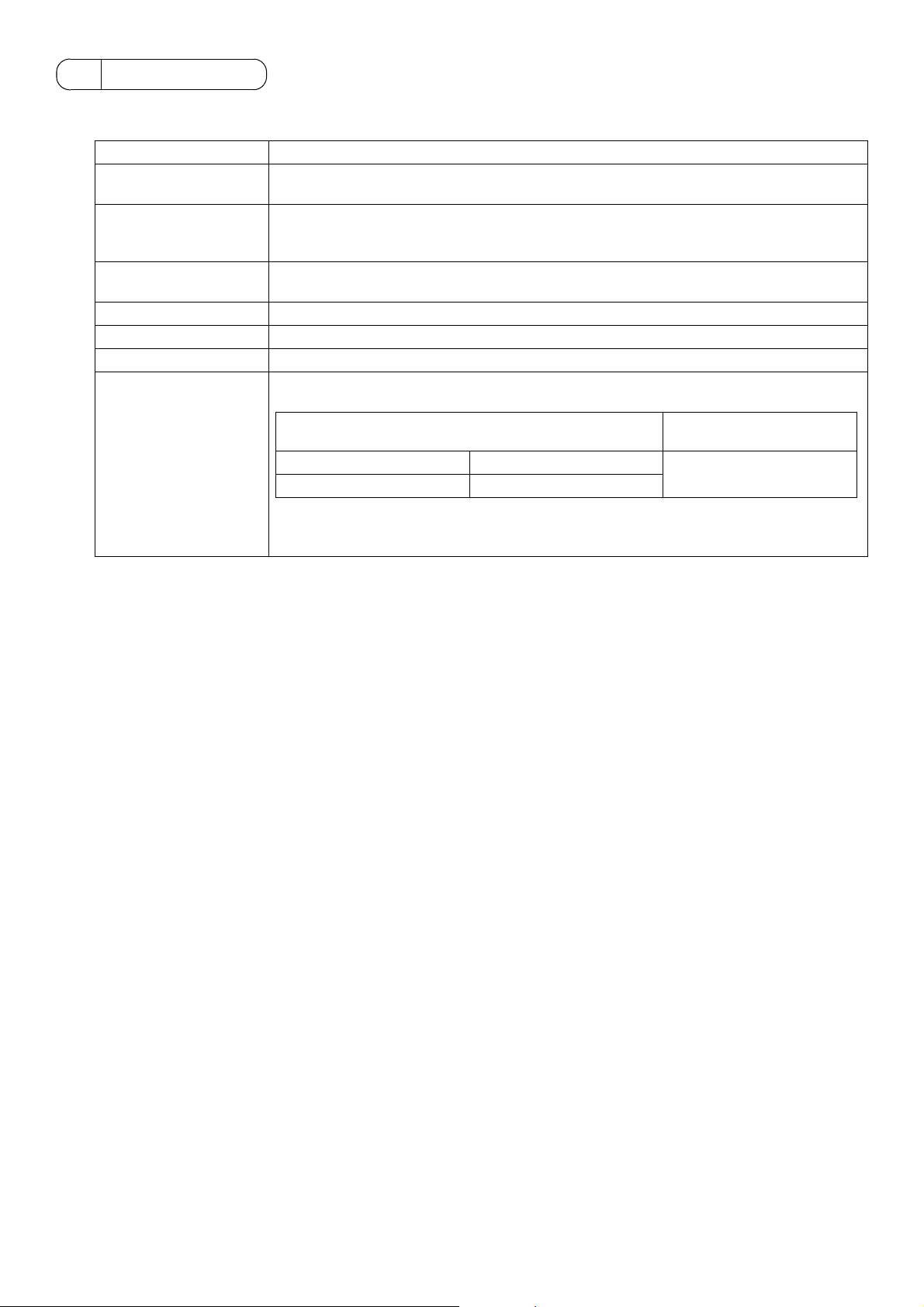
1 Specifications
1-1. Product Specifications
Items Spec
Power source
Interface
Ambient
conditions
Dimensions
Weight 2.8 kg (6-
Installation conditions Inside the control panel (indoor)
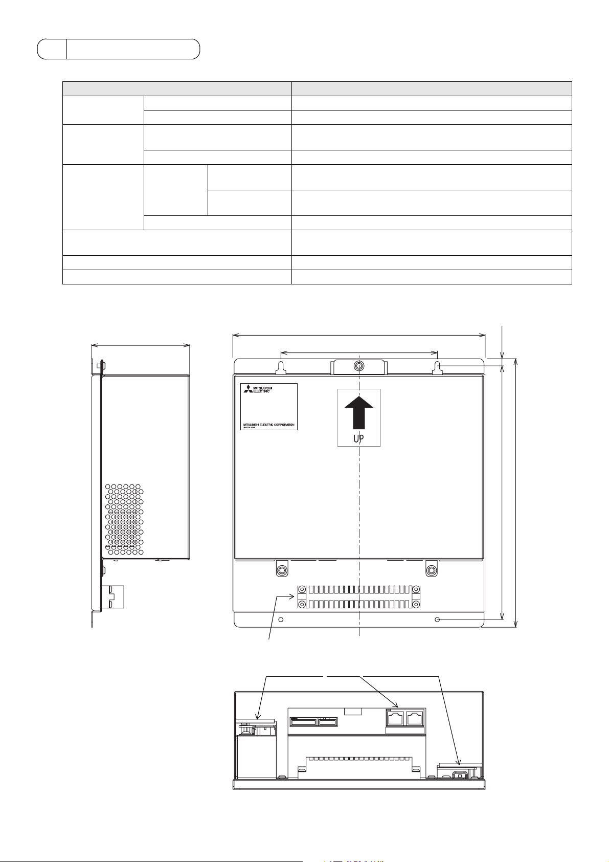
1-2. External dimensions
Rated input 100-240 VAC ±10 % 0.4-0.3 A 50/60 Hz
Fuse 250 VAC 3.15 A Time-delay type (IEC127-2 S.S.5)
Rated output of the power supply
to M-NET transmission lines
22-30 VDC
LAN 10Base-T or 100Base-TX (LAN2 is for future use.)
Temperature
Operating
temperature range
Storage
temperature range
-10 ~ 55°C (14 ~ 131°F)
-20 ~ 60°C (-4 ~ 140°F)
Humidity 30 ~ 90 %RH (Non-condensing)
266 (H) × 250 (W) × 97.2 (D) mm (10in)
3
/16 lbs.)
250(9-7/8)
7
97.2(3-
/8)
155(6-
1
/2 (H) × 9-7/8 (W) × 3-7/8 (D)
Unit: mm (in)
)
16
/
1
/8)
3
)
2
/
1
253.5(10) 5(
266(10-
Terminal block (to be used in the future when functions of the BAC-HD150 are upgraded.)
M-NET Terminal
block (M3.5)
Power source 100-240 VAC
Terminal block (M3.5)
LAN
LAN1 LAN2
- 4 -
Page 5
1-3. Power supply function to the M-NET transmission line
BAC-HD150 has a built-in function to supply power to the M-NET transmission line. (power supply coefficient: 6)
When power is supplied from BAC-HD150, the types of system controllers listed in the table below are connectable.
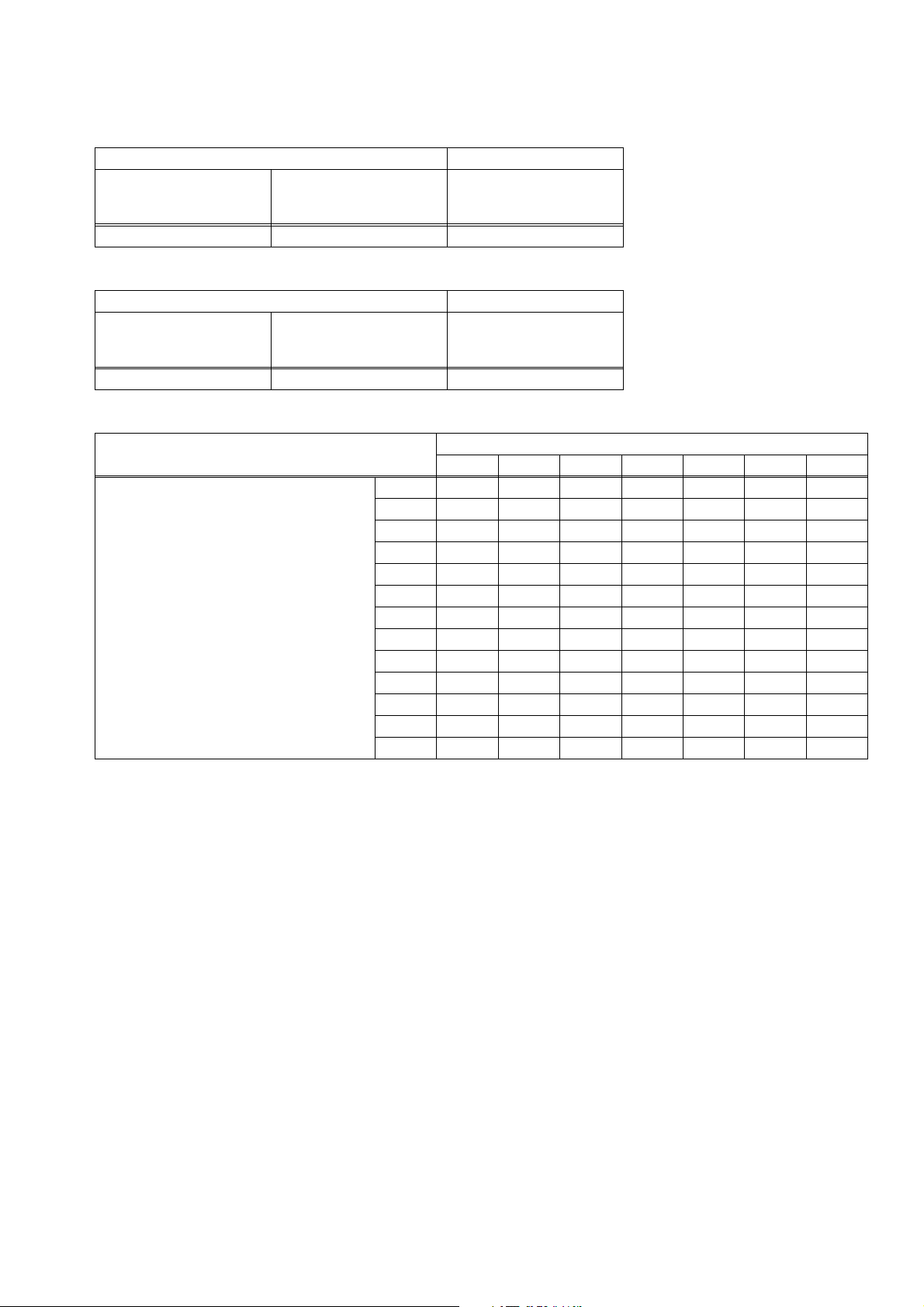
Table 1 Power consumption coefficient of the controller
System controller M-NET remote controller
System remote controller
ON/OFF remote controller
1 0.5 0.25
Table 2 No. of connected units
System controller M-NET remote controller
ON/OFF remote controller
6 units 12 units 24 units
Table 3 No. of connected units in systems with various combinations of remote controllers V: connectable
Total number of system remote controllers,
schedule timers, and group remote
controllers combined
Schedule timer
Group remote controller
System remote controller
Schedule timer
Group remote controller
0VVVVVVV
1VVVVVV
2VVVVVV
3VVVVV
4VVVVV
5VVVV
6VVVV
7VVV
8VVV
9VV
10 V V
11 V
12 V
ME remote controller
LOSSNAY remote
controller
ME remote controller
LOSSNAY remote
controller
Total number of ON/OFF remote controllers
0123456
- 5 -
Page 6
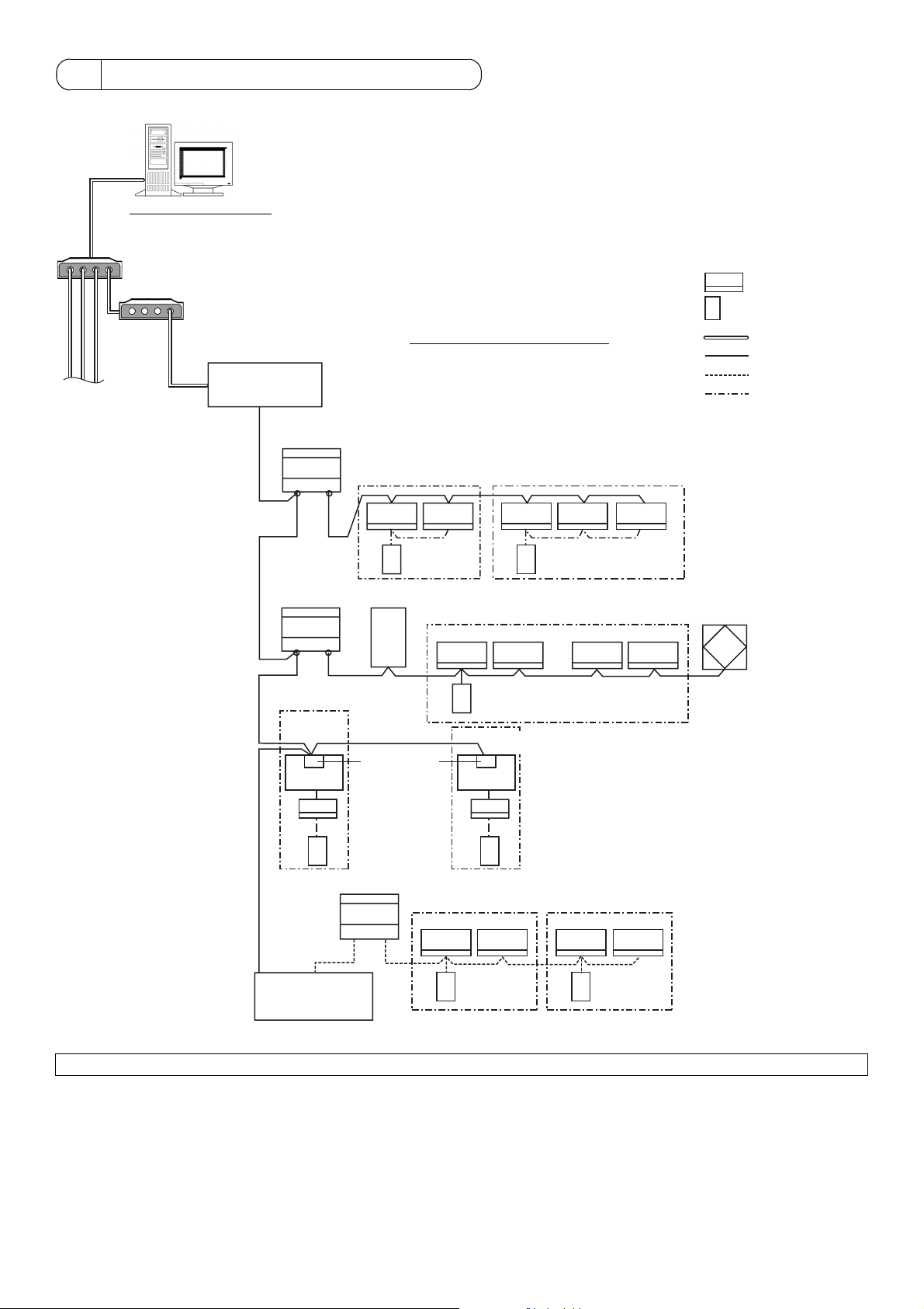
2 Sample system configuration
The figure below only shows the transmission line connections. Power supply lines are omitted.
Building management system
HUB
HUB
BACnet
BM ADAPTER
Model: BAC-HD150
[000]
M-NET
Outdoor unit
TB7 TB3
M-NET
Outdoor unit
TB7 TB3
Mr.Slim
outdoor unit
Mitsubishi Electric air conditioning system
[051]
Group 1 Group 2
[001] [002]
MA MA
R2
BC controller
[056]
[057]
[006]
ME
M-NET adapter
[11] [12]
Group 4
[003] [004] [005]
Group 3
[007] [008] [009]
[106]
Mr.Slim outdoor unit
Group 5
Indoor unit
Local remote controller
BACnet (LAN)
M-NET transmission line
K transmission line
MA remote controller line
The numbers in the [ ] indicate
the address No.
LOSSNAY
[010]
K-transmission converter
[213]
Model: PAC-SC25KAA
Note Use a switching HUB.
MA
K control
outdoor unit
TB7 TB3
MA
Group 13 Group 15
[13]
K
[14] [15]
[13]
K
- 6 -
[16]
[15]
Page 7

Q Address setting for various devices: The same address cannot be used more than once within the same system of the BM
ADAPTER (BAC-HD150). (K-control units and K-control remote control addresses are excluded.)
M-NET
address
1 ~ 50
Indoor unit
Address setting method
Assign the lowest address to the main indoor unit in the group, and assign sequential
addresses to the rest of the indoor units in the same group.
Outdoor unit Assign an address that equals the lowest indoor unit address in the group plus 50. 51 ~ 100
Auxiliary outdoor unit
(BC controller)
OA processing unit/
LOSSNAY
Mr.Slim outdoor unit
Assign an address that equals the address of the outdoor unit in the same refrigerant
system plus 1.
Assign an arbitrary but unused address to each of LOSSNAY units after assigning an
address to all indoor units.
Set the address in the same way as with the indoor units. An M-NET adapter (sold
separately) is required.
52 ~ 100
1 ~ 50
1 ~ 50
Assign an address that equals the address of the main indoor unit with the lowest
M-NET remote controller
address in the group plus 100.
101 ~ 200
Add 150 in stead of 100 to set a sub remote controller.
Address setting is not required.
MA remote controller
Connection of two remote controllers requires the main/sub setting for each
–
controller to be made.
Sub system controller Assign an address that equals the lowest number of the group to be controlled +200. 201 ~ 250
Assign an address to all M-NET indoor units (incl. LOSSNAY units) first, and then
K-control indoor unit
assign addresses to the K-control indoor unit, starting with the address after the last
1 ~ 50
address.
K-control remote
controller
Assign the same address as the lowest main K-control indoor unit address within the
same group.
1 ~ 50
K-transmission converter Assign an address that equals the lowest address of the K-control indoor units +200. 201 ~ 250
Important Check the setting for the central control switch SW2-1 on the M-NET outdoor unit.
(Refer to the outdoor unit Installation Manual for the detailed information about dip switch settings.)
Note the following when using a K-transmission converter (Model: PAC-SC25KAA) to control the K-control model
units.
Refer to the K-transmission converter Installation manual for details.
1 Be sure to set the BAC-HD150 address to "000."
2 Be sure to set the K-control air conditioning unit connection setting on the BAC-HD150 to Yes (set via the
Setting Tool).
When the above setting is made, enter the K-transmission converter address.
3 Assign addresses to the K-control air conditioners so that they are larger than the addresses that are
assigned to the M-control indoor units.
4 When making the group settings for the K-control units, make the group number and the lowest address of
the indoor units within the group the same.
5 If the K-control Y series units and other types of units (K-control Mr. Slim) are used in combination, a relay
board is required. The K- control Y series units cannot be connected to the same transmission lines as the
other types of units.
6 Depending on the number of K-control units and transmission line length, a relay board may be required.
Refer to the System Design/Manual (control version) for details.
7 LOSSNAY units cannot be connected if they are connected to the K-control kit.
8 Remote controller addresses do not need to be included in the group setting for the K-control units.
Note A-control jet burner models cannot be controlled.
Some models of units cannot be controlled.
* Main and sub system controllers (M-NET)
BAC-HD150 can only be used as the main system controller, but not as a sub system controller.
Main system controller (Main SC)
Main SC refers to a controller that controls all other system controllers including the units they control. If a given system
has only one system controller, that controller becomes the main SC. Group settings and interlock settings can only be
made from a main SC.
Sub system controller (Sub SC)
Sub SC refers to a system controller that is controlled (including the units it controls) by a main SC.
BAC-HD150
Main SC’s control range
(M-NET)
Sub SC’s
control range
Group Group
Group
BAC-HD150 is exclusively for use as a main SC. It cannot be used as a sub SC
or controlled from a main SC.
- 7 -
Page 8

Note
The system cannot be configured in the following way.
Groups that are not under the control of a main SC cannot be controlled from a sub SC.
Main SC Sub SC
Group Group Group
Each group cannot be under the control of two or more main SC.
Main SC 1 Main SC 2
Group Group Group
Sub SC cannot be under the control of two or more main SC.
Main SC 1 Sub SC Main SC 2
GroupGroup Group Group
- 8 -
Page 9
3Installation
3-1. Required parts
The following parts are required to install the unit.
Required parts Specification
Power cable/
Protective earth cable
M-NET transmission line
Ring terminal (with a
sleeve)
Screw Have four M4 screws ready to install the unit.
LAN cable 10Base-T or 100Base-TX (category 5 or above) straight cable (Maximum 100m (328 ft))
HUB Switching HUB (communication speed: 10 Mbps or 100 Mbps)
Overcurrent breaker and
Residual Current Circuit
Breaker (RCCB)
Power supply cable of appliances shall not be lighter than design 245 IEC 57 or 227 IEC 57.
Cable size:0.75mm² to 2mm²
Shielded cable
• CPEVS: φ1.2mm to φ1.6mm
• CVVS: 1.25mm² to 2mm²
M3.5 terminal (used with the power cable (L/L1, N/L2), M-NET transmission line (A, B, S))
M4 ring terminal (used with the protective earth cable)
Install an overcurrent breaker and a residual current circuit breaker (RCCB) for each BACHD150 unit.
Overcurrent breaker
Fuse Circuit breaker
*2
3A
*1 Use a circuit breaker and a residual current circuit breaker (RCCB) of bipolar type (2P2E).
Use a breaker with the minimum contact distance of 3 mm (1/8 in.).
*2 When using a fuse, use it in combination with a main switch (capacity: 3A).
3A
*1
Residual Current Circuit
Breaker (RCCB)
*1
3A 30mA
0.1 sec or less
- 9 -
Page 10

3-2. M-NET transmission line length
• Connect the BAC-HD150 to the transmission line for centralized control (TB7 on the outdoor unit).
• There should only be one power supply source within a single transmission circuit. The factory setting is that power is not
supplied from the BAC-HD150.
• Connect the shield of the M-NET transmission line for centralized control to the S terminal of TB3.
Provide an earth for the indoor-outdoor transmission lines at one single outdoor unit.
• Maximum line distance Maximum 500 m/1,640 ft*
• Maximum power supply distance Maximum 200 m/656 ft*
Maximum power supply distance is the distance in which a power supply unit (or an outdoor unit designated as a power
supply unit) is capable of supplying power to other units on the receiving end, such as remote controllers and indoor units.
1, 2
1
Sample wiring connection
BACnet (LAN)
M-NET transmission line
(centralized control)
M-NET transmission line
(indoor-outdoor)
BACnet (LAN)
BM ADAPTER
(BAC-HD150)
M-NET
(For centralized control)
L1
L2L3
Outdoor
unit
Outdoor
unit
Outdoor
unit
Outdoor
unit
(1) Maximum line distance
1 L1 + L2 + 5 + 1 + 2 ( 3) 500 m/1,640 ft
2 L1 + L2 + 5 + 4 500 m/1,640 ft
3 L1 + L3 + 6 + 7 ( 8) 500 m/1,640 ft
4 2 ( 3) + 1 + 5 + L2 + L3 + 6 + 7 ( 8) 500 m/1,640 ft
5 4 + 5 + L2 + L3 + 6 + 7 ( 8) 500 m/1,640 ft
M-NET (For indoor-outdoor transmission line)
1
Indoor unit Indoor unit Indoor unit
5
6
3
ME remote controller
Indoor unit Indoor unit Indoor unit
Indoor unit Indoor unit Indoor unit
8
ME remote controller
2
* To supply power from the BAC-HD150,
check that the power jumper is
connected to CN41. Refer to section
4-3 for details.
4
7
(2) Power supply distance for the indoor-outdoor transmission lines
1 5 + 1 + 2 ( 3) 200 m/656 ft
2 5 + 4 200 m/656 ft
CN40 CN41
outdoor unit
3 6 + 7 ( 8) 200 m/656 ft
(3) Power supply distance for the centralized control transmission lines
1 L1 + L2 200 m/656 ft
2 L1 + L3 200 m/656 ft
Note
*1 The ME remote controller wiring length ( 3, 8) should be 10 m (32 ft) or less.
The length that exceeds 10 m (32 ft) needs to be included in the maximum distance to the farthest unit (500 m/1,640 ft) and
the maximum power supply distance (200 m/656 ft).
*2 If the ME remote controller wiring length ( 3, 8) is 10 m (32 ft) or less, it does not need to be included in the maximum
distance to the farthest unit.
- 10 -
Page 11

3-3. Installation
• Leave enough space around the unit to allow for an installation/uninstallation of the cover.
• Screw down the cover with M4 screws as shown in the figure below.
Be sure to fix the four corners to prevent it from falling.
• Install on the control panel with an effective depth of at least 105mm (4-
)
16
/
13
20(
20(13/16) 20(13/16)
3
/16 in).
* Refer to section for the product dimensions and weight.
1 Specifications
Properly install the unit on a stable, load-bearing surface.
Unit installed on an unstable surface may fall and cause injury.
50(2)
Unit: mm (in)
To reduce the risk of wire shorting, fire, electric shock,
and malfunction, do not install the unit in a condensing
environment, and keep the unit out of water and other
sources of water.
- 11 -
Page 12

4 Wiring connections
WARNING • Electric work must be performed by an authorized technician. Improper wiring work may result in electric
shock or fire.
• Turn off the power supply before performing wiring work.
CAUTION • To avoid damage to the terminal block, do not connect an AC power supply (100-240 VAC) to the M-NET
transmission line terminal block.
4-1. Installing and uninstalling the cover
Unscrew the three screws on the cover to remove it as shown in the figure below.
Reinstall the cover using the three screws that were unscrewed.
4-2. Connecting the power cable and protective earth cable
• Connect the power cable and the protective earth cable as shown in the figure below.
Use an M3.5 ring terminal to the power cable, and connect an M4 ring terminal to the protective earth cable before
connecting them to their corresponding terminals (power supply terminal block or protective earth terminal).
• Be sure to connect the L2/N phase of the power cable to the L2/N side of the power supply terminal block (TB1).
• Secure cables with cable clamps.
Power supply
TB1
L/L1 N/L2
Power
cable
Power supply
100-240 VAC
50 Hz/60 Hz
B
B Residual current
circuit breaker
A Overcurrent breaker
Power cable
A
Protective earth cable
Earth
Cable
clamps
CAUTION • Install an overcurrent breaker and a residual current circuit breaker for the power wire to each BAC-HD150 unit.
Use a bipolar breaker (2P2E) with a minimum contact distance of 3 mm (
1
/8 in).
• Install a breaker for each BAC-HD150 so that turning off the power to one BAC-HD150 will not affect the rest of
the devices in the system.
• When using a fuse instead of an overcurrent breaker, use it in combination with a main switch (capacity: 3 A).
terminal block
Protective
earth terminal
Protective
earth cable
- 12 -
Page 13

4-3. Connecting the M-NET transmission lines
CN41
CN40
CN41
CAUTION • In an air conditioner system has more than 1 Outdoor units, System controller receiving transmission power
through TB7 on one of the Outdoor unit would have a risk that the connected Outdoor units failure would stop
power supply to System controller, and disrupt the whole system.
(1) Supplying power to the M-NET transmission line from the BAC-HD150
Connect the M-NET transmission lines and the power jumper as shown in the figure below.
Outdoor unit
M-NET
transmission line
(non-polarized)
BM ADAPTER
(BAC-HD150)
TB3
ABS
OFF
ONON
TB3
CN41
CN40CN40
M-NET
TB7
CN40 CN41
CN41
CAUTION • Connect the shield to the S terminal of TB3.
Insulate the cables with vinyl tape, except the part
that connects to the ring terminal.
• Connect the power jumper of BAC-HD150 to
CN40 (supplies power).
Connect the power jumper of the outdoor unit
to CN41 (does not supply power).
• Use the type of transmission lines specified, and
connect them to the appropriate terminals. Secure
the cables to keep undue force from being applied.
Improper connections or failure to properly secure
cables may result in overheating and fire.
Cable
clamps
Shield
(2) To not supply power to the M-NET transmission line from the BAC-HD150
Connect the M-NET transmission lines and the power jumper as shown in the figure below.
Power supply unit (PAC-SC51KUA...etc)
BM ADAPTER
(BAC-HD150)
M-NET
TB3
CAUTION • Connect the shield to the S terminal of TB3.
Insulate the cables with vinyl tape, except the part
that connects to the ring terminal.
• Connect the power jumper of BAC-HD150 to
CN41 (does not supply power at factory setting).
Connect the power jumper of the outdoor unit
to CN41 (does not supply power).
• Use the type of transmission lines specified, and
CN41
CN40CN40
connect them to the appropriate terminals. Secure
the cables to keep undue force from being applied.
Improper connections or failure to properly secure
TB3
OFF
ONON
cables may result in overheating and fire.
M-NET
transmission line
(non-polarized)
ABS
Outdoor unit
TB7
CN40
CN40
CN41
CN41
Cable
clamps
Shield
- 13 -
Page 14

4-4. Connecting the LAN cable
• Make sure that the LAN cable is long enough to reach the LAN1 connector on the BAC-HD150. Leave the LAN cable
disconnected until all the initial settings for the BAC-HD150 (IP address setting etc.) have been completed.
• Connect the BAC-HD150 (LAN1) and the building management system via a HUB.
• The maximum distance between the HUB and BAC-HD150 is 100 m (328 ft).
LAN1 LAN2 (for future use)
LAN1 LAN2
CAUTION • Install the LAN cable before installing the unit, and route the cable in the same way as the M-NET transmission
lines.
• Connect the BAC-HD150 to a private network. Use a security device such as a VPN router when connecting to
the Internet. (Without a proper security measure in place, the air conditioning system is vulnerable to access
from unauthorized users.)
5 Making the initial settings
Note
1. Turning on the power
Disconnect the LAN cable for connection to the BACnet before turning the power on for the first time.
There is a possibility that the IP address of the unit is already used by another device that is connected to the BACnet.
2. Initial settings
Make the initial setting using the Setting Tool after turning on the power to the BAC-HD150.
Some of the items that require initial settings include BAC-HD150 address and air conditioning system related items.
• IP address of BAC-HD150 (The factory setting for LAN1 is "192.168.1.254.")
• M-NET address of BAC-HD150 (The factory setting is "0.")
• Group configuration for the air conditioning system
Refer to the BAC-HD150 Instructions Manual and the Setting Tool Instructions Manual for detailed instructions for how to make
the initial settings.
Refer to the BAC-HD150 Instructions Manual and the Setting Tool Instructions Manual for how to make the initial
settings for the BAC-HD150.
6Test run
Note
Refer to the BAC-HD150 Instructions Manual and the installation manuals that came with the air conditioning units
for how to perform a test run for the BAC-HD150.
Refer to the installation manuals that came with the air conditioning units for how to perform a test run.
Perform a test run for the Mitsubishi Electric air conditioning system and confirm proper operation before connecting to the
building management system and performing a test run. (Refer to the BAC-HD150 Instructions Manual for details.)
- 14 -
Page 15

NOTE:
This equipment has been tested and found to comply with the limits for a Class B digital device, pursuant to
Part 15 of the FCC Rules. These limits are designed to provide resonable protection against harmful
interference in a residential installation. This equipment generates, uses and can radiate radio frequency
energy and, if not installed and used in accordance with the instructions, may cause harmful interference to
radio communications.
However, there is no guarantee that interference will not occur in a particular installation.
If this equipment does cause harmful interference to radio or television reception, which can be determined
by turning the equipment off and on, the user is encouraged to try to correct the interference by one or more
of the following measures:
- Reorient or relocate the receiving antenna.
- Increase the separation between the equipment and receiver.
- Connect the equipment into an outlet on a circuit different from that to which the receiver is connected.
- Consult the dealer or an experienced radio / TV technician for help.
Page 16
This product is designed and intended for use in the residential,
commercial and light-industrial environment.
The product at hand is
based on the following
EU regulations:
• Low Voltage Directive 2006/95/EC
• Electromagnetic Compatibility Directive,
2004/108/EC
Please be sure to put the contact address/telephone number on
this manual before handing it to the customer.
HEAD OFFICE: TOKYO BLDG. , 2-7-3, MARUNOUCHI, CHIYODA-KU, TOKYO 100-8310, JAPAN
Authorized representative in EU: MITSUBISHI ELECTRIC EUROPE B.V.
HARMAN HOUSE, 1 GEORGE STREET, UXBRIDGE, MIDDLESEX UB8 1QQ, U.K.
WT05543X01
Printed in Japan
Recycled Paper
 Loading...