

Mitsubishi Asx 2014 Owner's Manual

ASX - ENGLISH - OGAE14E1
ASX
OWNER’S MANUAL
ASX - ENGLISH - OGAE14E1
Foreword
E09200105666
Thank you for selecting an ASX as your new vehicle.
This owner’s manual will add to your understanding and full enjoyment of
the many fine features of this vehicle.
It contains information prepared to acquaint you with the proper way to operate and maintain your vehicle for the utmost in driving pleasure.
MITSUBISHI MOTORS Europe B.V. reserves the right to make changes in
design and specifications and/or to make additions to or improvements in
this product without obligation to install them on products previously manufactured.
It is an absolute requirement for the driver to strictly observe all laws and regulations concerning vehicles.
This owner’s manual has been written in compliance with such laws and regulations, but some of the contents may become contradictory with later amendment of the laws and regulations.
Please leave this owner’s manual in this vehicle at time of resale. The next
owner will appreciate having access to the information contained in this owner’s manual.
Repairs to your vehicle:
Vehicles in the warranty period:
All warranty repairs must be carried out by a MITSUBISHI MOTORS Authorized Service Point.
Vehicles outside the warranty period:
Where the vehicle is repaired is at the discretion of the owner.
Throughout this owner’s manual the words WARNING and CAUTION ap-
pear.
These serve as reminders to be especially careful. Failure to follow instructions could result in personal injury or damage to your vehicle.
WARNING
indicates a strong possibility of severe personal injury or death if instructions are not followed.
CAUTION
means hazards or unsafe practices that could cause minor personal injury or damage to your vehicle.
You will see another important symbol:
NOTE: gives helpful information.
*: indicates optional equipment.
It may differ according to the sales classification; refer
to the sales catalogue.
Abbreviations used in this owner’s manual:
LHD: Left-Hand Drive
RHD: Right-Hand Drive
M/T: Manual Transmission
A/T: Automatic Transmission
CVT: Continuously Variable Transmission
The symbol used on the vehicles:
: See owner’s manual
Information for station service
58 litres (For vehicles with vehicle identification numbers that be-
Fuel tank capacity
Petrol-powered vehicles
Fuel
Fuel requirements
Diesel-powered vehicles
Refer to the “General information” section for the fuel selection.
Engine oil Refer to the “Maintenance” section for the selection of engine oil.
Tyre inflation pressure Refer to the “Maintenance” section for the tyre inflation pressure.
2WD models
4WD models 60 litres
Unleaded petrol octane number (EN228)
1600 models, 1800 models
95 RON or higher
2000 models
90 RON or higher
Cetane number (EN590)
51 or higher
CAUTION
Your vehicle is designed to use only diesel fuel that meets the EN590 standard.
l
Use of any other type of diesel fuel can adversely affect the engine.
NOTE
For the location of the vehicle identification number, refer to “Vehicle identification number” on page 11-02.
l
63 litres (For vehicles with vehicle identification numbers that be-
E09300103878
gin with “4”)
gin with “J”)
© 2013 Mitsubishi Motors Corporation
OGAE14E1
BLC-13-001039
14

Table of contents
Overview
General information
Locking and unlocking
Seat and seat belts
Instruments and controls
Starting and driving
For pleasant driving
For emergencies
Vehicle care
Maintenance
Specifications
Alphabetical index
Declaration of Conformity
1
2
3
4
5
6
7
8
9
10
11
12
13
OGAE14E1

15
16
13
14
1
2
3
4
5
6
7
8
9
10
11
12
LHD
1
Instruments and controls
Instruments and controls
E00100108285
1. Combination headlamps and dipper switch p. 5-47
Turn-signal lever p. 5-54
Front fog lamp switch* p. 5-55
Rear fog lamp switch p. 5-55
Headlamp washer switch* p. 5-61
2. Instruments p. 5-02
3. Shift paddles* p. 6-34
4. Windscreen wiper and washer switch p. 5-56
Rear window wiper and washer switch p. 5-60
5. Engine switch* p. 3-13
6. Cruise control switch* p. 6-52
7. Ignition switch* p. 6-11
8. Supplemental restraint system - driver’s knee airbag* p. 4-29
9. Supplemental restraint system - airbag (for driver’s seat) p. 4-24,
4-29
Horn switch p. 5-62
10. Tilt & Telescopic steering lever p. 6-08
11. Bluetooth® 2.0 interface* p. 7-47
12. Steering wheel audio remote control switches* p. 7-25
13. Sonar switch* p. 6-60
14. Active stability control (ASC) OFF switch* p. 6-51
15. Headlamp levelling switch* p. 5-52
16. Auto Stop & Go (AS&G) OFF switch* p. 6-22
1-02
Overview
OGAE14E1

2
1
16
15
14
13
12
11
10
9
8
7
5
6
3
4
RHD
Instruments and controls
1
1. Instruments p. 5-02
2. Combination headlamps and dipper switch p. 5-47
Turn-signal lever p. 5-54
Front fog lamp switch* p. 5-55
Rear fog lamp switch p. 5-55
Headlamp washer switch* p. 5-61
3. Auto Stop & Go (AS&G) OFF switch* p. 6-22
4. Headlamp levelling switch* p. 5-52
5. Active stability control (ASC) OFF switch* p. 6-51
6. Sonar switch* p. 6-60
7. Cruise control switch* p. 6-52
8. Supplemental restraint system - airbag (for driver’s seat) p. 4-24,
4-29
Horn switch p. 5-62
9. Ignition switch* p. 6-11
10. Supplemental restraint system - driver’s knee airbag* p. 4-29
11. Bluetooth® 2.0 interface* p. 7-47
12. Steering wheel audio remote control switches* p. 7-25
13. Tilt & Telescopic steering lever p. 6-08
14. Engine switch* p. 3-13
15. Windscreen wiper and washer switch p. 5-56
Rear window wiper and washer switch p. 5-60
OGAE14E1
Overview
1-03

LHD
1
2
3
4
5
6
7
8
9
10
11
12
13
14
15
16
17
18
1
Instruments and controls
1. Audio system* p. 7-12
MITSUBISHI Multi-Communication System*
DISPLAY AUDIO*
Refer to the separate owner’s manual
2. Centre ventilators p. 7-02
3. Key slot* p. 3-20
4. Side ventilators p. 7-02
5. Front passenger’s airbag ON-OFF switch p. 4-27
Glove box p. 7-75
6. Hazard warning flasher switch p. 5-54
7. Rear window demister switch p. 5-61
8. Accessory socket p. 7-71
Cigarette lighter* p. 7-70
9. Gearshift or selector lever p. 6-22, 6-25, 6-31
10. Parking brake lever p. 6-06
11. Cup holder p. 7-78
12. Drive mode selector* p. 6-37
13. Ashtray* p. 7-70
14. Air conditioning* p. 7-03
15. Fuel tank filler door release lever p. 2-03
16. Bonnet release lever p. 10-03
17. Fuse box p. 10-19
18. Multi-information meter switch p. 5-05
1-04
Overview
OGAE14E1

RHD
Instruments and controls
1
1. Audio System* p. 7-12
MITSUBISHI Multi-Communication System*
DISPLAY AUDIO*
Refer to the separate owner’s manual
2. Multi-information meter switch p. 5-05
3. Bonnet release lever p. 10-03
4. Rear window demister switch p. 5-61
5. Accessory socket p. 7-71
6. Parking brake lever p. 6-06
7. Fuel tank filler door release lever p. 2-03
8. Cup holder p. 7-78
9. Drive mode selector* p. 6-37
10. Gearshift or selector lever p. 6-22, 6-25
11. Air conditioning* p. 7-03
12. Front passenger’s airbag ON-OFF switch p. 4-27
Glove box p. 7-75
Fuse box p. 10-19
13. Side ventilators p. 7-02
14. Key slot* p. 3-20
15. Hazard warning flasher switch p. 5-54
16. Centre ventilators p. 7-02
OGAE14E1
Overview
1-05

LHD
1
2
3
4
5
6
7
8
9
10
11
12
13
14
1
Interior
Interior
E00100206165
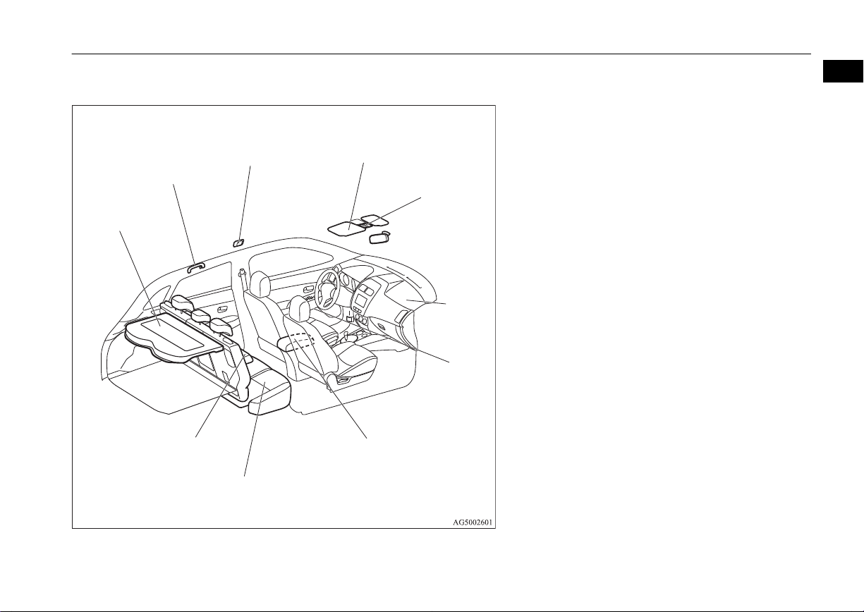
1. Lock switch p. 3-40
2. Electric remote-controlled outside rear-view mirrors switch
p. 6-09
3. Central door lock switch p. 3-26
4. Electric window control switch p. 3-39
5. Sunshade illumination dimming control switch* p. 7-74
6. Inside rear-view mirror p. 6-08
7. Front seat p. 4-03
Heated seat* p. 4-06
8. Supplemental restraint system - side airbag (for front seats)*
p. 4-33
9. Head restraints p. 4-07
10. Luggage room lamp p. 7-73
11. Luggage floor box* p. 7-78
12. Tether anchorages for child restraint system p. 4-22
13. Seat belts p. 4-09
Adjustable seat belt anchor p. 4-11
14. Supplemental restraint system - curtain airbag* p. 4-33
1-06
Overview
OGAE14E1
LHD
1
2
3
4
5
6
7
8
9
10
Interior
1
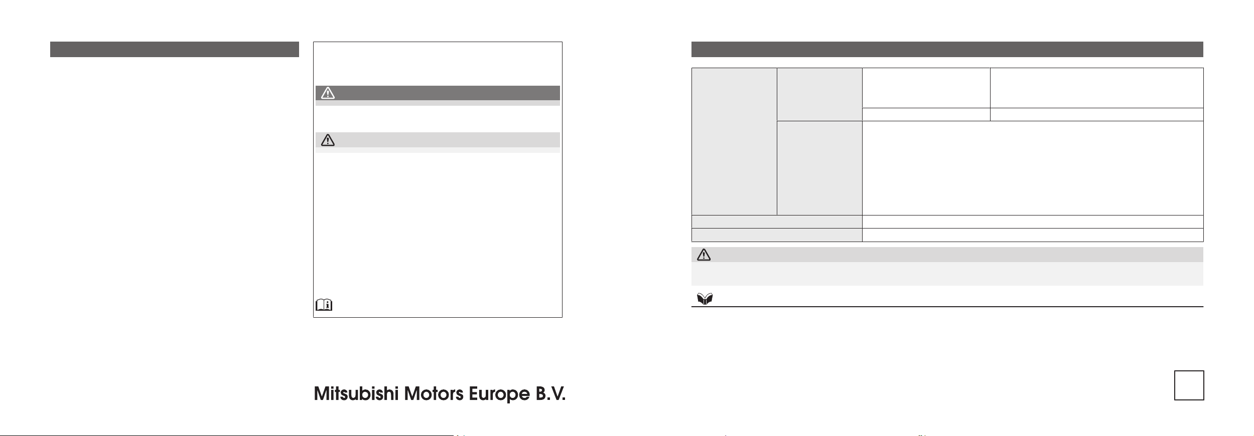
1. Rear shelf panel p. 7-79
2. Assist grip p. 7-80
Coat hook p. 7-80
3. Room lamp (rear)* p. 7-73
4. Sun visors p. 7-69
Vanity mirror p. 7-69
Card holder p. 7-69
5. Map lamp & room lamp (front) p. 7-72
Sunshade switch* p. 3-41
Microphone (for Bluetooth® 2.0 interface)* p. 7-48
6. Supplemental restraint system - airbag (for front passenger’s seat)
p. 4-24, 4-29
7. Bottle holder p. 7-79
8. Armrest* p. 4-05
Auxiliary Audio connector (RCA)* p. 7-36
USB input terminal* p. 7-66
Accessory socket p. 7-71
9. Rear seat p. 4-06
10. Armrest* p. 4-06
Cup holder* p. 7-78
OGAE14E1
Overview
1-07
RHD
1
2
3
4
5
6
7
8
9
10
11
12
13
14
1
Interior
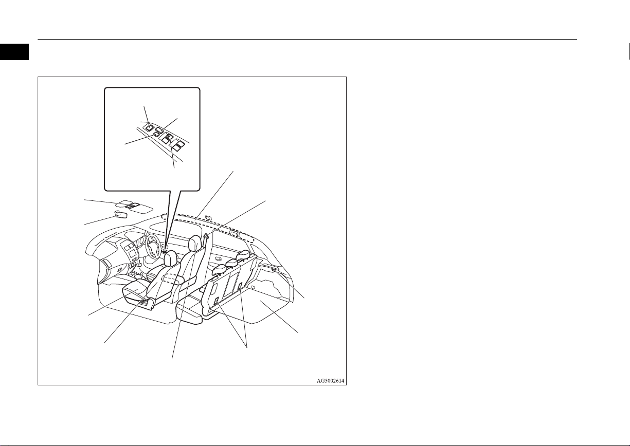
1. Supplemental restraint system - curtain airbag* p. 4-33
2. Seat belts p. 4-09
Adjustable seat belt anchor p. 4-11
3. Luggage room lamp p. 7-73
4. Luggage floor box* p. 7-78
5. Tether anchorages for child restraint system p. 4-22
6. Head restraints p. 4-07
7. Supplemental restraint system - side airbag (for front seats)*
p. 4-33
8. Front seat p. 4-03
Heated seat* p. 4-06
9. Inside rear-view mirror p. 6-08
10. Sunshade illumination dimming control switch* p. 7-74
11. Electric window control switch p. 3-39
12. Lock switch p. 3-40
13. Electric remote-controlled outside rear-view mirrors switch
p. 6-09
14. Central door lock switch p. 3-26
1-08
Overview
OGAE14E1
RHD
1
2
3
4
5
6
7
8
9
10
Interior
1
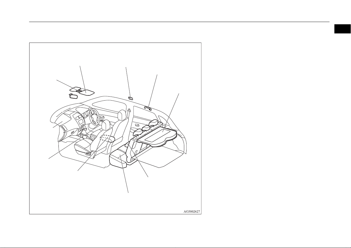
1. Map lamp & room lamp (front) p. 7-72
Sunshade switch* p. 3-41
Microphone (for Bluetooth® 2.0 interface)* p. 7-48
2. Sun visors p. 7-69
Vanity mirror p. 7-69
Card holder p. 7-69
3. Room lamp (rear)* p. 7-73
4. Assist grip p. 7-80
Coat hook p. 7-80
5. Rear shelf panel p. 7-79
6. Armrest* p. 4-06
Cup holder* p. 7-78
7. Rear seat p. 4-06
8. Armrest* p. 4-05
Auxiliary Audio connector (RCA) p. 7-36
USB input terminal* p. 7-66
Accessory socket p. 7-71
9. Bottle holder p. 7-79
10. Supplemental restraint system - airbag (for front passenger’s seat)
p. 4-24, 4-29
OGAE14E1
Overview
1-09

Vehicle with the tyre repair kit
Luggage compartment
1
Luggage compartment
E00100402837
1. Tyre repair kit* p. 8-07
2. Luggage hook p. 7-81
3. Jack p. 8-06
4. Tools p. 8-06
5. Luggage hook p. 7-81
6. Hook
7. Luggage hook p. 7-81
8. Tools p. 8-06
1-10
Overview
OGAE14E1
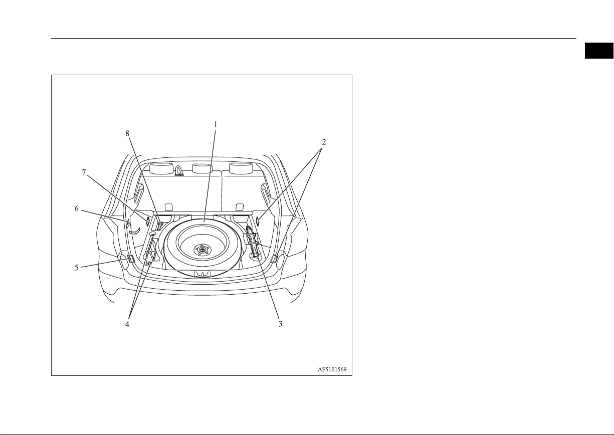
Vehicle with the spare tyre
Luggage compartment
1
1. Spare wheel p. 8-14
2. Luggage hook p. 7-81
3. Jack p. 8-06
4. Tools p. 8-06
5. Luggage hook p. 7-81
6. Hook
7. Luggage hook p. 7-81
8. Tools p. 8-06
OGAE14E1
Overview
1-11

11
1
2
3
4
5
6
7
8
9
10
1
Exterior
Exterior
E00100505422
1. Electric window control p. 3-39
2. Fuel tank filler p. 2-03
3. Outside rear-view mirror p. 6-09
Side turn-signal lamps* p. 5-54, 10-26, 10-31
4. Side turn-signal lamps* p. 5-54, 10-26, 10-31
5. Position lamps p. 5-47, 10-26, 10-30
6. Headlamps, low beam p. 5-47, 10-26, 10-27, 10-29
7. Front fog lamps* p. 5-55, 10-26, 10-31
Daytime running lamps* p. 10-26, 10-32
8. Headlamps, high-beam p. 5-47, 10-26, 10-29
9. Front turn-signal lamps p. 5-54, 10-26, 10-30
10. Bonnet p. 10-03
11. Windscreen wipers p. 5-56
1-12
Overview
OGAE14E1
1
2
3
4
5
6
7
8
9
10
11
12
13
14
15
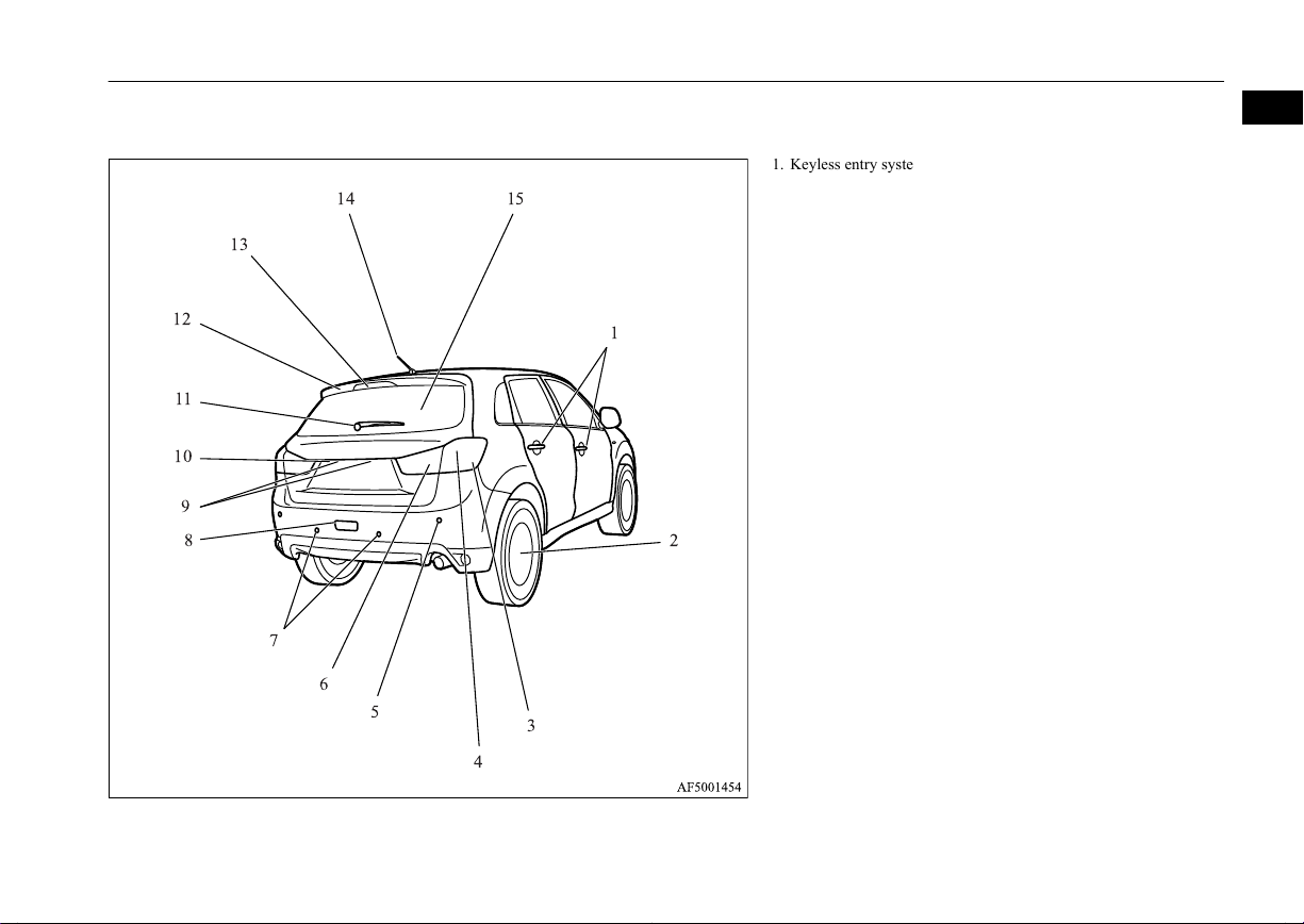
Exterior
1
1. Keyless entry system* p. 3-04
Keyless operation system* p. 3-07
Locking and unlocking the doors p. 3-25
2. Changing tyres p. 8-13
Tyre inflation pressures p. 10-13
Tyre rotation p. 10-14
Tyre chains p. 10-15
Size of tyres and wheels p. 11-12
3. Turn-signal lamps/Hazard warning lamps p. 5-54, 5-54, 10-26,
10-34
4. Stop lamps/Tail lamps p. 5-47, 10-26, 10-34
5. Corner sensors* p. 6-58
6. Reversing lamps p. 5-47, 10-26, 10-35
7. Back sensors* p. 6-57
8. Rear fog lamp* p. 5-55, 10-26, 10-33
9. Licence plate lamps p. 5-47, 10-26, 10-36
10. Rear-view camera* p. 6-61
11. Rear window wiper p. 5-60
12. Rear spoiler p. 9-04
13. High-mounted stop lamp p. 10-26
14. Antenna p. 7-46
15. Tailgate p. 3-30
OGAE14E1
Overview
1-13

OGAE14E1

General information
Fuel selection...................................................................................... 2-02
Filling the fuel tank.............................................................................2-03
Installation of accessories................................................................... 2-04
Modification/alterations to the electrical or fuel systems................... 2-05
Genuine parts...................................................................................... 2-05
Safety and disposal information for used engine oil...........................2-05
Disposal information for used batteries.............................................. 2-06
Auto Stop & Go (AS&G) system*..................................................... 2-06
2
OGAE14E1

Fuel selection
Fuel selection
2
Recommended
fuel
CAUTION
For petrol-powered vehicles, the use of lea-
l
ded fuel can result in serious damage to the
engine and catalytic converter. Do not use
leaded fuel.
Diesel-powered vehicles are designed to use
l
only diesel fuel that meets the EN590 standard.
Use of any other type of diesel fuel (bio diesel, methylester, etc.) would adversely affect
the engine’s performance and durability.
Petrol-powered vehicles
Unleaded petrol octane
number (EN228)
1600 models, 1800 models
95 RON or higher
2000 models
90 RON or higher
Diesel-powered vehicles
Cetane number (EN590)
51 or higher
E00200103076
NOTE
Petrol-powered vehicles have the knock con-
l
trol system so that you can use unleaded petrol 90 RON as an emergent measure in case
unleaded petrol 95 RON or higher is not
available on journey, etc.
In such a case, you don’t need to adjust the
engine specially. In case of using unleaded
petrol 90 RON, the engine performance level is reduced.
For diesel fuel, due to the separation of par-
l
affin, the fluidity of the fuel decreases considerably as the temperature falls.
Because of this fact there are two kinds of
fuel: “summer” and “winter”.
This must be considered in winter use.
Select either of the two kinds of fuel in accordance with ambient temperature.
Above -5 °C: “Summer” diesel
Below -5 °C: “Winter” diesel
When travelling abroad, find out in advance
about the fuels served in local service stations.
NOTE
Repeatedly driving short distances at low
l
speeds can cause deposits to form in the fuel
system and engine, resulting in poor starting
and poor acceleration. If these problems occur, you are advised to add a detergent additive to the gasoline when you refuel the vehicle. The additive will remove the deposits,
thereby returning the engine to a normal
condition. Be sure to use a MITSUBISHI
MOTORS GENUINE FUEL SYSTEM
CLEANER. Using an unsuitable additive
could make the engine malfunction. For details, please contact a MITSUBISHI
MOTORS Authorized Service Point.
Poor quality petrol can cause problems such
l
as difficult starting, stalling, engine noise
and hesitation. If you experience these problems, try another brand and/or grade of petrol.
If the check engine warning lamp flashes,
have the system checked as soon as possible
at a MITSUBISHI MOTORS Authorized
Service Point.
E10 type petrol
The petrol engines are compatible with
type petrol (containing 10 % ethanol) conforming to European standards EN 228.
E00203200022
E10
2-02
General information
OGAE14E1
LHD
RHD
Filling the fuel tank
CAUTION
Do not use more than 10 % concentration of
l
ethanol (grain alcohol) by volume.
Use of more than 10 % concentration may
lead to damage to your vehicle fuel system,
engine, engine sensors and exhaust system.
Filling the fuel tank
WARNING
When handling fuel, comply with the safe-
l
ty regulations displayed by garages and
filling stations.
Gasoline is highly flammable and explo-
l
sive. You could be burned or seriously injured when handling it. When refueling
your vehicle, always turn the engine off
and keep away from flames, sparks, and
smoking materials. Always handle fuel in
well-ventilated outdoor areas.
Before removing the fuel cap, be sure to
l
get rid of your body’s static electricity by
touching a metal part of the car or the
fuel pump. Any static electricity on your
body could create a spark that ignites fuel
vapour.
Perform the whole refueling process
l
(opening the fuel tank filler door, removing the fuel cap, etc.) by yourself. Do not
let any other person come near the fuel
tank filler. If you allowed a person to help
you and that person was carrying static
electricity, fuel vapour could be ignited.
E00200203699
WARNING
Do not move away from the fuel tank fill-
l
er until refueling is finished. If you moved
away and did something else (for example, sitting on a seat) part-way through
the refueling process, you could pick up a
fresh charge of static electricity.
If the tank cap must be replaced, use only
l
a MITSUBISHI MOTORS original part.
Fuel tank capacity
2WD models: 58 litres (For vehicles with vehicle identification numbers that begin with
“4”)
2WD models: 63 litres (For vehicles with vehicle identification numbers that begin with
“J”)
4WD models: 60 litres
NOTE
For the location of the vehicle identification
l
number, refer to “Vehicle identification
number” on page 11-02.
Refueling
1. Before filling with fuel, stop the engine.
2. The fuel tank filler is located on the rear
left side of your vehicle.
Open the fuel tank filler door by pulling
the release lever located on the side of
the driver’s seat.
3. Remove the fuel cap.
2
OGAE14E1
General information
2-03

Installation of accessories
Open the fuel tank filler tube by slowly
turning the cap anticlockwise.
2
1- Remove
2- Close
4. While filling with fuel, hang the fuel cap
cord on the hook located on the inside of
the fuel tank filler door.
CAUTION
Since the fuel system may be under pressure,
l
remove the fuel cap slowly. This relieves
any pressure or vacuum that might have
built up in the fuel tank. If you hear a hissing
sound from the cap, wait until it stops before
removing the cap. Otherwise, fuel may spray
out, injuring you or others.
5. Insert the gun in the tank port as far as it
goes.
CAUTION
Do not tilt the gun.
l
6. When the gun stops automatically, do
not fill with fuel any more.
7. Close the fuel cap.
To close, turn the fuel cap slowly clockwise until you hear clicking sounds, then
gently push the fuel tank filler door
closed.
Installation of accessories
E00200300963
We recommend you to consult a
MITSUBISHI MOTORS Authorized Service
Point.
The installation of accessories, optional
l
parts, etc., should only be carried out
within the limits prescribed by law in
your country, and in accordance with the
guidelines and warnings contained within the documents accompanying this vehicle.
Installing electric components incorrect-
l
ly could lead to a fire. Please refer to
Modification/alteration to the electrical
or fuel systems section within this owner’s manual.
Using a cellular phone or radio set inside
l
the vehicle without an external antenna
may cause electrical system interference,
which could lead to unsafe vehicle operation.
Tyres and wheels which do not meet
l
specifications must not be used.
Refer to the “Specifications” section for
information regarding wheel and tyre
sizes.
Important points!
Due to large number of accessory and replacement parts of different manufactures
available in the market, it is not possible, not
only for MITSUBISHI MOTORS, but also
for a MITSUBISHI MOTORS Authorized
Service Point, to check whether the attachment or installation of such parts affects the
overall safety of your MITSUBISHI-vehicle.
2-04
General information
OGAE14E1
Modification/alterations to the electrical or fuel systems
Even when such parts are officially authorized, for example by a “general operators
permit” (an appraisal for the part) or through
the execution of the part in an officially approved manner of construction, or when a
single operation permit following the attachment or installation of such parts, it cannot be
deduced from that alone, that the driving
safety of your vehicle has not been affected.
Consider also that there basically exists no liability on the part of the appraiser or the official. Maximum safety can only be ensured
with parts recommended, sold and fitted or
installed by a MITSUBISHI MOTORS Authorized Service Point (MITSUBISHI
MOTORS genuine replacement parts and
MITSUBISHI MOTORS accessories). The
same also pertains to modifications of
MITSUBISHI vehicles with respect to the
production specifications. For safety reasons,
do not attempt any modifications other than
those that follow the recommendations of a
MITSUBISHI MOTORS Authorized Service
Point.
Modification/alterations to
the electrical or fuel systems
E00200400368
MITSUBISHI MOTORS CORPORATION
has always manufactured safe, high quality
vehicles. In order to maintain this safety and
quality, it is important that any accessory that
is to be fitted, or any modifications carried
out which involve the electrical or fuel systems, should be carried out in accordance
with MITSUBISHI guidelines.
CAUTION
If the wires interfere with the vehicle body
l
or improper installation methods are used
(protective fuses not included, etc.), electronic devices may be adversely affected, resulting in a fire or other accident.
Genuine parts
E00200500499
MITSUBISHI MOTORS has gone to great
lengths to bring you a superbly crafted automobile offering the highest quality and dependability.
Use MITSUBISHI MOTORS Genuine Parts,
designed and manufactured to maintain your
MITSUBISHI MOTORS automobile at top
performance. MITSUBISHI MOTORS Genuine Parts are identified by this mark and are
available at all MITSUBISHI MOTORS Authorized Service Points.
Safety and disposal information for used engine oil
E00200600155
WARNING
Prolonged and repeated contact may
l
cause serious skin disorders, including
dermatitis and cancer.
Avoid contact with the skin as far as pos-
l
sible and wash thoroughly after any contact.
Keep used engine oils out of reach of chil-
l
dren.
2
OGAE14E1
General information
2-05

Disposal information for used batteries
Protect the environment
It is illegal to pollute drains, water courses
2
and soil. Use authorized waste collection facilities, including civic amenity sites and garages providing facilities for disposal of used
oil and used oil filters. If in doubt, contact
your local authority for advice on disposal.
Disposal information for
used batteries
Your vehicle contains batteries and/or accumulators.
Do not mix with general
household waste.
For proper treatment, recovery and recycling of used batteries, please take them to applicable collection points, in
accordance with your national legislation and the Directives 2006/66/EC.
By disposing of these batteries correctly, you will help to
save valuable resources and
prevent any potential negative effects on human health
and the environment which
could otherwise arise from
inappropriate waste handling.
E00201300032
Auto Stop & Go (AS&G) system*
E00201500021
This paragraph summarizes the major items
of the Auto Stop & Go (AS&G) system
such as the characteristics, operating procedures, etc. For details, refer to “Auto Stop &
Go (AS&G) system” on page 6-18.
The Auto Stop & Go (AS&G) system reduces the emission of exhaust gases and increases fuel efficiency.
The Auto Stop & Go (AS&G) system automatically stops and restarts the engine without the use of the ignition switch or the engine switch when the vehicle is stopped, such
as at traffic lights or in a traffic jam.
Activation
E00201600051
The Auto Stop & Go (AS&G) system is automatically activated when the ignition switch
is turned to the “ON” position or the operation mode is put in ON.
Deactivation
E00201700065
You can deactivate the system by pressing
the “Auto Stop & Go (AS&G) OFF” switch.
Then the “ ” display/indicator will turn on.
Auto stop
E00201800066
1. Stop the vehicle.
2-06
General information
OGAE14E1

Vehicles with 5M/T Vehicles with 6M/T
Auto Stop & Go (AS&G) system*
2. Place the gearshift lever in the “N”
(Neutral) position.
3. Release the clutch pedal.
4. The “ ” display/indicator will turn on
and the engine will stop automatically.
Auto go
E00201900067
Depress the clutch pedal while the gearshift
lever is in the “N” (Neutral) position. The
“ ” display/indicator turns off and the engine restarts automatically.
System characteristics
E00202300055
The principle of the Auto Stop & Go
(AS&G) system is that it adapts to the vehicle’s needs (i.e. energy supply). This means
that in certain circumstances the engine will
not stop and in other circumstances the engine will restart by itself.
Circumstances when the engine will restart by itself
The interior temperature rises and the air
l
conditioning starts operating in order to
lower the temperature.
Electric power consumption is high.
l
The brake pedal is depressed repeatedly.
l
Vehicle speed is 3 km/h (2 mph) or
l
higher when coasting on a slope.
Mode selection dial is set to the demister
l
position.
When the air conditioning is operated by
l
pressing the air conditioning switch.
When the preset temperature of the air
l
conditioning is changed significantly.
When the air conditioning is operated in
l
AUTO mode where the temperature control dial is set to the max. hot or the max.
cool position (for vehicles with automatic air conditioning).
Other than the conditions mentioned above,
the engine may restart automatically. For details, refer to “Auto Stop & Go (AS&G) system” on page 6-18.
E00202400027
Circumstances when the engine will not stop
Ambient temperature is lower than ap-
l
proximately 3 °C.
E00202500044
2
OGAE14E1
General information
2-07

Auto Stop & Go (AS&G) system*
After the engine restarts automatically
l
and the vehicle stops again within 10
2
seconds.
After the engine restarts automatically
l
and the vehicle remains stationary.
Mode selection dial is set to the demister
l
position (see illustration below).
When the air conditioning is operated in
l
AUTO mode where the temperature control dial is set to the max. hot or the max.
cool position (for vehicles with automatic air conditioning).
Other than the conditions mentioned above,
the engine may not stop automatically. For
details, refer to “Auto Stop & Go (AS&G)
system” on page 6-18.
2-08
General information
OGAE14E1

Locking and unlocking
Keys.................................................................................................... 3-02
Electronic immobilizer (Anti-theft starting system)........................... 3-03
Keyless entry system*.........................................................................3-04
Keyless operation system*..................................................................3-07
Doors...................................................................................................3-25
Central door locks............................................................................... 3-26
Dead Lock System*............................................................................ 3-27
“Child-protection” rear doors..............................................................3-30
Tailgate................................................................................................3-30
Inside tailgate release.......................................................................... 3-31
Security alarm system*....................................................................... 3-32
Electric window control...................................................................... 3-39
Sunshade*........................................................................................... 3-41
3
OGAE14E1

Keys
Keys
Type 1
3
The key fits all locks.
1- Keyless entry key
(with electronic immobilizer)
2- Key number tag
E00300102269
Type 2
The emergency key fits all locks.
1- Keyless operation key
(with electronic immobilizer and keyless
entry system function)
2- Emergency key
3- Key number tag
WARNING
When taking a key on flights, do not press
l
any switches on the key while on the
plane. If a switch is pressed on the plane,
the key emits electromagnetic waves,
which could adversely affect the plane’s
flight operation.
When carrying a key in a bag, be careful
that no switches on the key can be easily
pressed by mistake.
NOTE
The key number is stamped on the tag as in-
l
dicated in the illustration.
Make a record of the key number and store
the key and key number tag in separate places, so that you can order a key in the event
the original keys are lost.
The key is a precision electronic device with
l
a built-in signal transmitter. Please observe
the following in order to prevent a malfunction.
Do not leave in a place that is exposed to
•
direct sunlight, for example on the dashboard.
Do not disassemble or modify.
•
Do not excessively bend the key or sub-
•
ject it to strong impacts.
Do not expose to water.
•
Keep away from magnetic key rings.
•
Keep away from audio systems, personal
•
computers, TVs, and other equipment that
generates a magnetic field.
Keep away from devices that emit strong
•
electromagnetic waves, such as cellular
phones, wireless devices and high frequency equipment (including medical devices).
Do not clean with ultrasonic cleaners or
•
similar equipment.
Do not leave the key where it may be ex-
•
posed to high temperature or high humidity.
3-02
Locking and unlocking
OGAE14E1

Electronic immobilizer (Anti-theft starting system)
NOTE
The engine is designed so that it will not
l
start if the ID code registered in the immobilizer computer and the key’s ID code do
not match. Refer to the “Electronic immobilizer” section for details and key usage.
[For vehicles equipped with the security
l
alarm system]
Pay attention to the following if the security
alarm is set to “Active”.
Refer to “Security alarm system” on page
3-32.
If the security alarm is in the system
•
armed mode, the alarm will sound if the
doors are opened after being unlocked
with the key, the inside lock knob or the
central door lock switch.
Even if the security alarm is set to “Ac-
•
tive”, the system preparation mode is not
entered if the keyless entry system or the
keyless operation function was not used to
lock the vehicle.
Electronic immobilizer
(Anti-theft starting system)
E00300203078
[For vehicles equipped with keyless operation system]
For information on operations for vehicles
equipped with the keyless operation system,
refer to “Keyless operation system: Electronic immobilizer (Anti-theft starting system)”
on page 3-12.
[Except vehicles equipped with keyless operation system]
The electronic immobilizer is designed to
significantly reduce the possibility of vehicle
theft. The purpose of the system is to immobilize the vehicle if an invalid start is attempted. A valid start attempt can only be achieved by using a key “registered” to the immobilizer system.
NOTE
In the following cases, the vehicle may not
l
be able to receive the registered ID code
from the registered key and the engine may
not start.
When the key contacts a key ring or other
•
metallic or magnetic object
When the key grip contacts metal of an-
•
other key
NOTE
When the key contacts or is close to other
•
immobilizing keys (including keys of other vehicles)
In cases like these, remove the object or
additional key from the vehicle key. Then
try again to start the engine. If the engine
does not start, we recommend you to con-
3
OGAE14E1
Locking and unlocking
3-03

Keyless entry system*
NOTE
tact your MITSUBISHI MOTORS Authorized Service Point.
If you lose one of them, contact a
l
3
MITSUBISHI MOTORS Authorized Service Point as soon as possible. To obtain a replacement or extra spare key, take your vehicle and all remaining keys to your
MITSUBISHI MOTORS Authorized Service Point. All the keys have to be re-registered in the immobilizer computer unit. The
immobilizer can register up to 8 different
keys.
Keyless entry system*
E00300302649
Press the remote control switch, and all doors
and the tailgate will be locked or unlocked as
desired. It is also possible to operate the outside rear-view mirrors (Vehicles equipped
with the mirror retractor switch).
CAUTION
Do not modify or add parts to the immobiliz-
l
er system. Doing so could cause the immobilizer to malfunction.
1- LOCK switch
2- UNLOCK switch
3- Indication lamp
To lock
Press the LOCK switch (1). All the doors and
the tailgate will be locked. The turn-signal
lamps will blink once when the doors and the
tailgate are locked.
NOTE
With a vehicle that has a Dead Lock System,
l
pressing the LOCK switch (1) two times in
succession causes the Dead Lock System to
be set. (Refer to “Setting the system” on
page 3-27.)
To unlock
Press the UNLOCK switch (2). All the doors
and the tailgate will be unlocked. If the doors
and tailgate are unlocked when the front
room lamp switch is in the “DOOR” position
or the rear room lamp switch (except for vehicles equipped with the sunshade) is in the
middle (•) position, the room lamp will illuminate for approximately 15 seconds and the
turn-signal lamps will blink twice.
Depending on the vehicle model, the position
and tail lamps can also be set to turn on for
approximately 30 seconds. Refer to “Instruments and controls: Welcome light” on page
5-51.
NOTE
The remote control switch does not operate
l
in the following conditions:
The key is left in the ignition switch.
•
A door or the tailgate is open or ajar. (On-
•
ly the unlock function operates.)
3-04
Locking and unlocking
OGAE14E1
Keyless entry system*
NOTE
Except for vehicles equipped with a Dead
l
Lock System, the door and tailgate unlock
function can be set so that only the driver’s
door unlocks when the UNLOCK switch (2)
is pressed once.
If the door and tailgate unlock function is set
to work as described above, all the doors and
the tailgate unlock when the UNLOCK
switch is pressed two times in succession.
Refer to “Setting of door and tailgate unlock
function” on page 3-06.
The indication lamp (3) comes on each time
l
a switch is pressed.
For vehicles equipped with the mirror retrac-
l
tor switch, the outside rear-view mirrors automatically retract or extend when all the
doors and tailgate are locked or unlocked using the remote control switches of the keyless entry system.
Refer to “Starting and driving: Outside rearview mirrors” on page 6-09.
If the UNLOCK switch (2) is pressed and no
l
door or tailgate is opened within approximately 30 seconds, relocking will automatically occur.
It is possible to modify functions as follows:
l
For further information, please contact your
MITSUBISHI MOTORS Authorized Service Point.
The time for automatic relocking can be
•
changed.
NOTE
The confirmation function (flashing of the
•
turn-signal lamps) can be set to operate
only when the doors and backdoor are
locked or only when the doors and backdoor are unlocked.
The confirmation function (this indicates
•
locking or unlocking of the doors and tailgate with the flash of the turn-signal
lamps) can be deactivated.
The number of times the turn-signal
•
lamps are flashed by the confirmation
function can be changed.
Operation of the Dead Lock System
In a vehicle that has a Dead Lock System, it
is possible to set the Dead Lock System using
the remote controller.
(Refer to “Dead Lock System” on page
3-27.)
Operation of the outside rearview mirrors (Vehicles equipped with mirror retractor
switch)
E00310800236
To fold
Within 30 seconds of locking the doors and
tailgate using the LOCK switch (1), press the
LOCK switch twice rapidly to fold the outside rear-view mirrors.
To extend
Within 30 seconds of unlocking the doors
and tailgate using the UNLOCK switch (2),
press the UNLOCK switch twice rapidly to
return the outside rear-view mirrors to their
extended positions.
The outside rear-view mirrors are not initially set to work as described above. If you
want them to work as described above, you
need to set them so that they do not retract/
extend when the doors and tailgate are
locked/unlocked using the keyless entry system or keyless operation system.
Refer to “Starting and driving: Outside rearview mirrors” on page 6-09.
For details, please consult a MITSUBISHI
MOTORS Authorized Service Point.
3
OGAE14E1
Locking and unlocking
3-05

Keyless entry system*
NOTE
The outside rear-view mirrors cannot be fol-
l
ded or extended using the remote control
3
switch in the following conditions:
The key is left in the ignition switch.
•
A door or the tailgate is open or ajar.
•
The remote control switch will operate with-
l
in approximately 4 m from the vehicle.
However, the operating range of the remote
control switch may change if the vehicle is
located near a power station, or radio/TV
broadcasting station.
If either of the following problems occurs,
l
the battery may be exhausted.
The remote control switch is operated at
•
the correct distance from the vehicle, but
the doors and tailgate are not locked/
unlocked in response.
The indication lamp (3) is dim or does not
•
come on.
For further information, please contact
your MITSUBISHI MOTORS Authorized
Service Point.
If you replace the battery yourself, refer to
“Procedure for replacing the remote control switch battery” on page 3-06.
If your remote control switch is lost or dam-
l
aged, please contact your MITSUBISHI
MOTORS Authorized Service Point for a replacement remote control switch.
NOTE
If you wish to add a remote control switch,
l
we recommend you to contact a
MITSUBISHI MOTORS Authorized Service Point.
A maximum of 8 remote control switches
are available for your vehicle.
Setting of door and tailgate unlock function (Except for vehicles equipped with a Dead
Lock System)
The door and tailgate unlock function can be
set to the following two conditions.
Each time the door and tailgate unlock function is set, a chime will sound to tell you the
condition of the door and tailgate unlock
function.
Number of
chimes
One chime
All doors and the tailgate unlock
Condition
Two chimes Driver’s door unlock only
1. Remove the key from the ignition
E00310300257
switch.
2. Place the combination headlamps and
dipper switch in the “OFF” position, and
3. Press and hold the LOCK switch (1) for
4 to 10 seconds and then also press the
UNLOCK switch (2) during this time.
4. Release in sequence the LOCK and UNLOCK switches within 10 seconds of
pressing the LOCK switch in step 3.
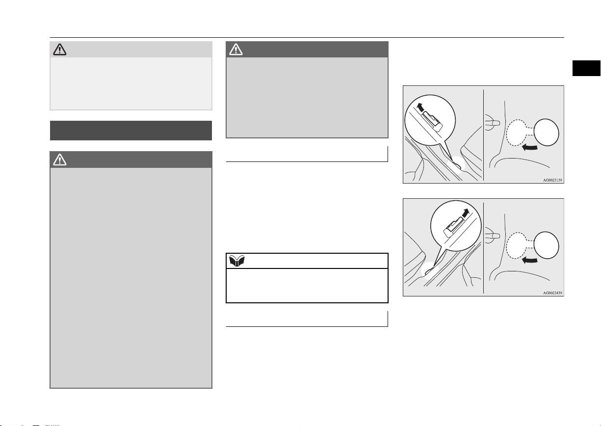
Procedure for replacing the remote control switch battery
E00309500145
1. Before replacing the battery, remove
static electricity from your body by
touching a metal part such as a doorknob
of the room.
2. Remove the screw (A) from the remote
control switch.
3. With the MITSUBISHI mark facing
you, insert the cloth-covered tip of a
straight blade (or minus) screwdriver in-
leave the driver’s door open.
3-06
Locking and unlocking
OGAE14E1
 Loading...