

Mitsubishi Electric Artisan MELSEC-Q, Artisan MELSEC-A, Artisan MELSEC-QnA, Artisan MELSEC-AnS, Artisan MELSEC-QnAS Series Manual
...
Artisan Technology Group is your source for quality
new and certied-used/pre-owned equipment
• FAST SHIPPING AND
DELIVERY
• TENS OF THOUSANDS OF
IN-STOCK ITEMS
• EQUIPMENT DEMOS
• HUNDREDS OF
MANUFACTURERS
SUPPORTED
• LEASING/MONTHLY
RENTALS
• ITAR CERTIFIED
SECURE ASSET SOLUTIONS
SERVICE CENTER REPAIRS
Experienced engineers and technicians on staff
at our full-service, in-house repair center
Instra
Remotely inspect equipment before purchasing with
our interactive website at www.instraview.com
Contact us: (888) 88-SOURCE | sales@artisantg.com | www.artisantg.com
SM
REMOTE INSPECTION
View
WE BUY USED EQUIPMENT
Sell your excess, underutilized, and idle used equipment
We also offer credit for buy-backs and trade-ins
www.artisantg.com/WeBuyEquipment
LOOKING FOR MORE INFORMATION?
Visit us on the web at www.artisantg.com for more
information on price quotations, drivers, technical
specications, manuals, and documentation
Mitsubishi General-purpose Programmable Controllers
MELSEC-A/QnA (Large), AnS/QnAS (Small)
Transition Examples
Dec. 2014 Edition
Artisan Technology Group - Quality Instrumentation ... Guaranteed | (888) 88-SOURCE | www.artisantg.com

Under some circumstances, failure to observe the precautions given under " CAUTION" may lead
to serious consequences.
Observe the precautions of both levels because they are important for personal and system safety.
Make sure that the end users read this publication and keep it in a safe place for future reference.
Before using products introduced in this publication, please read this Transition
Examples and relevant manuals carefully and pay full attention to safety to handle
the product correctly.
In this publication, the safety precautions are classified into two levels:
" WARNING" and " CAUTION".
CAUTION
WARNING
Indicates that incorrect handling may cause hazardous conditions,
resulting in death or severe injury.
Indicates that incorrect handling may cause hazardous conditions,
resulting in minor or moderate injury or property damage.
● Configure safety circuits external to the programmable controller to ensure that the entire system operates
safely even when a fault occurs in the external power supply or the programmable controller. Failure to do
so may result in an accident due to an incorrect output or malfunction.
(1) Configure external safety circuits, such as an emergency stop circuit, protection circuit, and protective
interlock circuit for forward/reverse operation or upper/lower limit positioning.
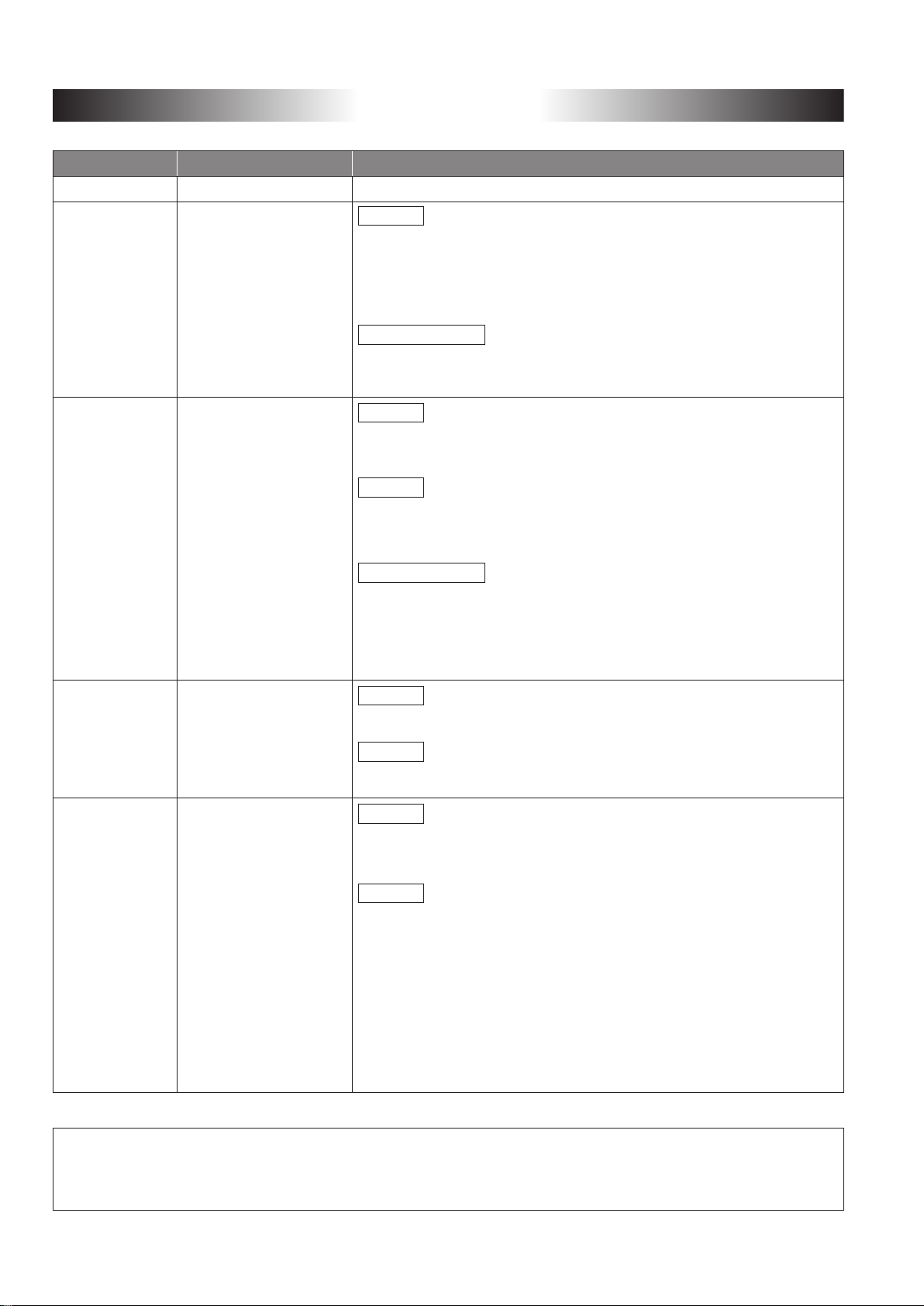
(2) The programmable controller stops its operation upon detection of the following status, and the output
status of the system will be as shown below.
All outputs may turn on when an error occurs in the part, such as I/O control part, where the CPU module
cannot detect any error. To ensure safety operation in such a case, provide a safety mechanism or a
fail-safe circuit external to the programmable controller. For a fail-safe circuit example, refer to LOADING
AND INSTALLATION in the QCPU User's Manual (Hardware Design, Maintenance and Inspection).
(3) Outputs may remain on or off due to a failure of an output module relay or transistor. Configure an
external circuit for monitoring output signals that could cause a serious accident.
Q Series ModuleStatus
All out puts are turned off.
A/AnS Series module
All out puts are turned off.
All out puts are turned off.
Overcurrent or overvoltage protection of
the power supply module is activated.
The CPU module detects an error such as
a watchdog timer error by the self-diagnostic
function.
All outputs are held or turned
off according to the parameter
setting.
WARNING
Artisan Technology Group - Quality Instrumentation ... Guaranteed | (888) 88-SOURCE | www.artisantg.com
Safety Precautions
● When replacing A (Large Type)/AnS (Small Type) Series with Q Series ●
Before using products introduced in this publication, please read this Transition
Examples and relevant manuals carefully and pay full attention to safety to handle
the product correctly.
In this publication, the safety precautions are classified into two levels:
" WARNING" and " CAUTION".
Indicates that incorrect handling may cause hazardous conditions,
WARNING
CAUTION
Under some circumstances, failure to observe the precautions given under " CAUTION" may lead
to serious consequences.
Observe the precautions of both levels because they are important for personal and system safety.
resulting in death or severe injury.
Indicates that incorrect handling may cause hazardous conditions,
resulting in minor or moderate injury or property damage.
Make sure that the end users read this publication and keep it in a safe place for future reference.
Design Precautions
WARNING
● Configure safety circuits external to the programmable controller to ensure that the entire system operates
safely even when a fault occurs in the external power supply or the programmable controller. Failure to do
so may result in an accident due to an incorrect output or malfunction.
(1) Configure external safety circuits, such as an emergency stop circuit, protection circuit, and protective
interlock circuit for forward/reverse operation or upper/lower limit positioning.
(2) The programmable controller stops its operation upon detection of the following status, and the output
status of the system will be as shown below.
Overcurrent or overvoltage protection of
the power supply module is activated.
The CPU module detects an error such as
a watchdog timer error by the self-diagnostic
function.
Q Series ModuleStatus
All out puts are turned off.
All outputs are held or turned
off according to the parameter
setting.
A/AnS Series module
All out puts are turned off.
All out puts are turned off.
All outputs may turn on when an error occurs in the part, such as I/O control part, where the CPU module
cannot detect any error. To ensure safety operation in such a case, provide a safety mechanism or a
fail-safe circuit external to the programmable controller. For a fail-safe circuit example, refer to LOADING
AND INSTALLATION in the QCPU User's Manual (Hardware Design, Maintenance and Inspection).
(3) Outputs may remain on or off due to a failure of an output module relay or transistor. Configure an
external circuit for monitoring output signals that could cause a serious accident.
Artisan Technology Group - Quality Instrumentation ... Guaranteed | (888) 88-SOURCE | www.artisantg.com
1
Design Precautions
WARNING
● In an output module, when a load current exceeding the rated current or an overcurrent caused by a load
short-circuit flows for a long time, it may cause smoke and fire. To prevent this, configure an external safety
circuit, such as a fuse.
● Configure a circuit so that the programmable controller is turned on first and then the external power supply.
If the external power supply is turned on first, an accident may occur due to an incorrect output or
malfunction.
● For the operating status of each station after a communication failure, refer to relevant manuals for the
network.
Incorrect output or malfunction due to a communication failure may result in an accident.
● When controlling (changing data) the running programmable controller from a peripheral connected to the
CPU module or from a personal computer connected to an intelligent function module, configure an interlock
circuit in the sequence program to ensure that the entire system will always operate safely.
For other controls for the running programmable controller (program modification and operating status
change (status control)), read relevant manuals carefully, and ensure the safety before operation.
Especially, in the case of a control from an external device to a remote programmable controller, immediate
action cannot be taken for a problem on the programmable controller due to a communication failure.
Configure an interlock circuit in the sequence program, and determine corrective actions to be taken
between the external device and CPU module in case of a communication failure.
CAUTION
● Do not install the control lines or communication cables together with the main circuit lines or power cables.
Keep a distance of 100mm (3.94 inches) or more between them.
Failure to do so may result in malfunction due to noise.
● When a device such as a lamp, heater, or solenoid valve is controlled through an output module, a large
current (approximately ten times greater than normal) may flow when the output is turned from off to on.
Take measures such as replacing the module with one having a sufficient current rating.
● The time for the CPU module to enter the RUN status after the CPU module is powered off and on or reset
will vary depending on the system configuration, parameter settings, and/or program size, etc.
Design the program so that the entire system will operate safely even if the time to reach the RUN status
varies.
Artisan Technology Group - Quality Instrumentation ... Guaranteed | (888) 88-SOURCE | www.artisantg.com
2

Installation Precautions
CAUTION
● Use the programmable controller in an environment that meets the general specifications in the QCPU
User's Manual (Hardware Design, Maintenance and Inspection).
Failure to do so may result in electric shock, fire, malfunction, or damage to or deterioration of the product.
● To mount the module, while pressing the module mounting lever located in the lower part of the module, fully
insert the module fixing projection(s) into the hole(s) in the base unit and press the module until it snaps into
place.
Incorrect mounting may cause malfunction, failure or drop of the module.
When using the programmable controller in an environment of frequent vibrations, fix the module with a
screw.
Tighten the screw within the specified torque range.
Undertightening can cause drop of the screw, short circuit or malfunction.
Overtightening can damage the screw and/or module, resulting in drop, short circuit, or malfunction.
● When using an extension cable, connect it to the extension cable connector of the base unit securely.
Check the connection for looseness.
Poor contact may cause incorrect input or output.
● When using an SD memory card, fully insert it into the SD memory card slot.
Check that it is inserted completely.
Poor contact may cause malfunction.
● When using an extended SRAM cassette, fully insert it into the cassette connector on the CPU module.
Close the cassette cover to keep the extended SRAM cassette inserted completely.
Poor contact may cause malfunction.
● Shut off the external power supply for the system in all phases before mounting or removing the module.
Failure to do so may result in damage to the product.
A module can be replaced online (while power is on) on any MELSECNET/H remote I/O station or in the
system where a CPU module supporting the online module change function is used.
Note that there are restrictions on the modules that can be replaced online, and each module has its
predetermined replacement procedure.
For details, refer to the relevant sections in the QCPU User's Manual (Hardware Design, Maintenance and
Inspection) and in the manual for the corresponding module.
● Do not directly touch any conductive part or electronic component of the module, memory card, SD memory
card or extended SRAM cassette. Doing so can cause malfunction or failure.
● When using a motion CPU module and a motion module, make sure that proper modules are combined
before turning on power. If improper modules are used, they may be damaged. For details, refer to the
Motion CPU Module User's Manual.
Artisan Technology Group - Quality Instrumentation ... Guaranteed | (888) 88-SOURCE | www.artisantg.com
3
Wiring Precautions
WARNING
● Shut off the external power supply for the system in all phases before mounting or wiring the module.
Failure to do so may result in electric shock or damage to the product.
● After mounting or wiring, attach the included terminal cover onto the module before turning the power on or
starting operation.
Failure to do so may result in electric shock.
CAUTION
● Ground the FG and LG terminals to the dedicated conductors for the programmable controller (Class D
(Class 3) or higher grounding).
Failure to do so may result in electric shock or malfunction.
● Use applicable solderless terminals and tighten them within the specified torque range.
If any spade solderless terminal is used, it may be disconnected when the terminal screw comes loose,
resulting in failure.
● Check the rated voltage and terminal layout before wiring to the module, and connect the cables correctly.
Inputting voltage different from the rated voltage, connecting a power supply with a different voltage rating or
incorrect wiring may cause a fire or failure.
● Connectors for external connection must be crimped or pressed with the tool specified by the manufacturer,
or must be correctly soldered.
Incomplete connections could result in short circuit, fire, or malfunction.
● Fit the connectors surely to the module. Poor contact may cause malfunction.
● Do not bundle the control cable or communication cable with the main circuit or power wire, or lay them
adjacently.
Separate these by 100 mm or more.
Failure to observe this could lead to malfunctioning caused by noise.
● When connecting any cable, check the type of the interface to be connected.
Connecting to an improper interface or incorrect wiring may damage the module and external devices.
● Tightening the terminal screws within the specified torque range.
Under tightening the terminal screws can cause short circuit, a fire or malfunction.
Overtightening can damage the screw and/or module, resulting in drop, short circuit, or malfunction.
● Prevent foreign matter such as dust or wire chips from entering the module.
Such foreign matter can cause a fire, failure, or malfunction.
● A protective film is attached to the top of the module to prevent foreign matter, such as wire chips, from
entering the module during wiring.
Do not remove the film during wiring.
Remove it for heat dissipation before system operation.
● When disconnecting any cable from the module, do not pull the cable.
When disconnecting a cable with a connector, hold the connector of the connecting part of the module.
Before disconnecting a cable from the terminal block, loosen the terminal screw on the terminal block.
Pulling the cable with the terminal connected to the module may cause malfunction or damage to the
module or cable.
● Mitsubishi programmable controllers must be installed in control panels.
Connect the main power supply to the power supply module in the control panel through a relay terminal
block.
Wiring and replacement of a power supply module must be performed by maintenance personnel who is
familiar with protection against electric shock. (For wiring methods, refer to the QCPU User's Manual
(Hardware Design, Maintenance and Inspection)).
Artisan Technology Group - Quality Instrumentation ... Guaranteed | (888) 88-SOURCE | www.artisantg.com
4
Startup and Maintenance Precautions
WARNING
● Do not touch any terminal while power is on.
Doing so will cause electric shock.
● Correctly connect the battery connector.
The battery must not be charged, disassembled, heated, thrown into the fire, short-circuited, soldered,
wetted with a liquid or exposed to strong shock.
Doing so will cause the battery to produce heat, explode, or ignite, resulting in injury and fire.
● Shut off the external power supply for the system in all phases before cleaning the module or retightening
the terminal screws or module fixing screws.
Failure to do so may result in electric shock, damage to the module and malfunction.
CAUTION
● Before performing online operations (especially, program modification, forced output, and operation status
change) for the running CPU module from the peripheral connected, read relevant manuals carefully and
ensure the safety.
Improper operation may damage machines or cause accidents.
● Do not disassemble or modify the modules.
Doing so may cause failure, malfunction, injury, or a fire.
● Use any radio communication device such as a cellular phone or PHS (Personal Handy-phone System)
more than 25cm (9.85 inches) away in all directions from the programmable controller.
Failure to do so may cause malfunction.
● Shut off the external power supply for the system in all phases before mounting or removing the module.
Failure to do so may cause the module to fail or malfunction.
A module can be replaced online (while power is on) on any MELSECNET/H remote I/O station or in the
system where a CPU module supporting the online module change function is used.
Note that there are restrictions on the modules that can be replaced online, and each module has its
predetermined replacement procedure.
For details, refer to the relevant sections in the QCPU User's Manual (Hardware Design, Maintenance and
Inspection) and in the manual for the corresponding module.
● Connection/disconnection of the module to/from the base unit and the extended SRAM cassette and
terminal block to/from the CPU module after the first use of the product shall be limited to 50 times.
(Compliant with JIS B 3502)
Exceeding the limit of 50 times may cause malfunction.
● Connection/disconnection of the SD memory card after the first use of the product shall be limited to 500
times. Exceeding the limit of 500 times may cause malfunction.
● Do not drop or apply shock to the battery to be installed in the module.
Doing so may damage the battery, causing the battery fluid to leak inside the battery.
If the battery is dropped or any shock is applied to it, dispose of it without using.
● Before handling the module, touch a grounded metal object to discharge the static electricity from the human
body.
Failure to do so may cause the module to fail or malfunction.
Artisan Technology Group - Quality Instrumentation ... Guaranteed | (888) 88-SOURCE | www.artisantg.com
5
Disposal Precautions
CAUTION
● When disposing of this product, treat it as industrial waste.
When disposing of batteries, separate them from other wastes according to the local regulations.
(For details of the battery directive in EU member states, refer to the QCPU User's Manual
(Hardware Design, Maintenance and Inspection).)
Transportation Precautions
CAUTION
● When transporting lithium batteries, follow the transportation regulations.
(For details of the regulated models, refer to the QCPU User's Manual (Hardware Design, Maintenance and
Inspection).)
Artisan Technology Group - Quality Instrumentation ... Guaranteed | (888) 88-SOURCE | www.artisantg.com
6
● When replacing AnS (Small Type) Series with L Series ●
Before using products introduced in this publication, please read this Transition
Examples and relevant manuals carefully and pay full attention to safety to handle
the product correctly.
In this publication, the safety precautions are classified into two levels:
" WARNING" and " CAUTION".
Indicates that incorrect handling may cause hazardous conditions,
WARNING
CAUTION
Under some circumstances, failure to observe the precautions given under " CAUTION" may lead
to serious consequences.
Observe the precautions of both levels because they are important for personal and system safety.
resulting in death or severe injury.
Indicates that incorrect handling may cause hazardous conditions,
resulting in minor or moderate injury or property damage.
Make sure that the end users read this publication and keep it in a safe place for future reference.
Artisan Technology Group - Quality Instrumentation ... Guaranteed | (888) 88-SOURCE | www.artisantg.com
7

WARNING
Design Precautions
●
Configure safety circuits external to the programmable controller to ensure that the entire system operates
safely even when a fault occurs in the external power supply or the programmable controller. Failure to do so
may result in an accident due to an incorrect output or malfunction.
(1) Configure external safety circuits, such as an emergency stop circuit, protection circuit, and protective
interlock circuit for forward/reverse operation or upper/lower limit positioning.
(
2) The mechanical zero return of the positioning function is controlled based on two parameters, zero
return direction and zero return speed, and deceleration is started when the near-point dog is turned
on. Therefore, if the zero return direction is set incorrectly, the positioning function may continue the
operation without deceleration. Configure an interlock circuit for prevention of mechanical damage on the
outside of the programmable controller.
(3) When the CPU module detects an error during operation of the positioning function, the function will
decelerate and stop.
(4) The programmable controller stops its operation upon detection of the following status, and the output
status of the system will be as shown below.
• When the overcurrent or overvoltage protection of the power supply module is activated, all outputs
will be turned off.
• When the CPU module detects an error such as a watchdog timer error by the self-diagnostic
function, all outputs will be held or turned off according to the parameter setting.
All outputs may turn on when an error occurs in the part, such as I/O control part, where the
CPU module cannot detect any error. To ensure safety operation in such a case, provide a safety
mechanism or a fail-safe circuit external to the programmable controller. For a fail-safe circuit
example, refer to LOADING AND INSTALLATION in the LCPU User's Manual (Hardware Design,
Maintenance and Inspection).
(5) Outputs may remain on or off due to a failure of a transistor on an output circuit. Configure an external
circuit for monitoring output signals that could cause a serious accident.
●
In an output circuit, when a load current exceeding the rated current or an overcurrent caused by a load
short-circuit flows for a long time, it may cause smoke and fire. To prevent this, configure an external safety
circuit, such as a fuse.
●
Configure a circuit so that the programmable controller is turned on first and then the external power supply.
If the external power supply is turned on first, an accident may occur due to an incorrect output or
malfunction.
●
Configure a circuit so that the external power supply is turned off before the programmable controller is
turned off.
If the programmable controller is turned off first, an accident may occur due to an incorrect output or
malfunction.
●
For the operating status of each station after a network communication failure, refer to relevant manuals for
the network. Incorrect output or malfunction due to a communication failure may result in an accident.
●
When changing data of the running programmable controller from a peripheral connected to the CPU
module, configure an interlock circuit in the program to ensure that the entire system will always operate
safely.
For other controls for the running programmable controller (program modification and operating status
change (status control)), read relevant manuals carefully, and ensure the safety before operation.
Especially, in the case of a control from an external device to a remote programmable controller, immediate
action cannot be taken for a problem on the programmable controller due to a communication failure.
Configure an interlock circuit in the program, and determine corrective actions to be taken between the
external device and CPU module in case of a communication failure.
●
If an absolute position is recovered by the positioning function, the servo ON signal may be kept off (the
servo may be kept off) for approx. 20 ms, and the motor may operate. If any problem is caused by the motor
operation when the servo ON signal is turned off, provide an electromagnetic brake so that the motor will be
locked during absolute position recovery.
Artisan Technology Group - Quality Instrumentation ... Guaranteed | (888) 88-SOURCE | www.artisantg.com
8
CAUTION
WARNING
CAUTION
Design Precautions
WARNING
●
Do not bundle the control cable or communication cable with the main circuit or power wire, or lay them
adjacently. Separate these by 100 mm or more as a rule.
Failure to observe this could lead to malfunctioning caused by noise.
●
When a lamp load or an inductive load, such as a heater and a solenoid valve, is controlled, a large current
(approximately ten times greater than normal) may flow when the output is turned from off
module having a sufficient current rating.
●
The time for the CPU module to enter the RUN status after the CPU module is powered off and on or reset
will vary depending on the system configuration, parameter settings, and/or program size, etc. Design the
program so that the entire system will operate safely even if the time to reach the RUN status varies.
to on. Use a
Installation Precautions
●
Shut off the external power supply for the system in all phases before mounting or removing the module.
Failure to do so may cause electric shock, damage to the module or malfunction.
●
Use the programmable controller in an environment that conforms to "GENERAL SPECIFICATIONS" in the
LCPU User's Manual (Hardware Design, Maintenance and Inspection).
Failure to do so may result in electric shock, fire, malfunction, or damage to or deterioration of the product.
●
To mount modules, engage their connectors, slide them until the module connecting hook stops, and lock the
hook securely.
Incorrect mounting may cause malfunction, failure or drop of the module.
●
Do not directly touch any conductive part or electronic component of any module.
Doing so can cause malfunction or failure of the module.
●
When using an extension cable, connect it to the extension connectors of the branch module and extension
module. After connecting, check the connections for looseness.
Poor contact may cause malfunction.
●
When using an SD memory card, fully insert it into the SD memory card slot. Check that it is inserted completely.
Poor contact may cause malfunction.
●
Do not directly touch any conductive part or electronic component of the module or SD memory card.
Doing so can cause malfunction or failure.
Wiring Precautions
●
Shut off the external power supply for the system in all phases before wiring the module.
Failure to do so may result in electric shock or failure or malfunction of the module.
●
After mounting or wiring, attach the included terminal cover onto the module before turning the power on or
starting operation.
Failure to do so may result in electric shock.
Artisan Technology Group - Quality Instrumentation ... Guaranteed | (888) 88-SOURCE | www.artisantg.com
9

CAUTION
Wiring Precautions
●
Ground the FG and LG terminals to the dedicated conductors for the programmable controller (Class D
(Class 3) or higher grounding).
Failure to do so may result in electric shock or malfunction.
●
Use applicable solderless terminals and tighten them within the specified torque range.
If any spade solderless terminal is used, it may be disconnected when the terminal screw comes loose,
resulting in failure.
●
C
heck the rated voltage and terminal layout before wiring to the module, and connect the cables correctly.
Inputting voltage different from the rated voltage, connecting a power supply with a different voltage rating or
incorrect wiring may cause a fire or failure.
●
Connectors for external connection must be crimped or pressed with the tool specified by the manufacturer,
or must be correctly soldered.
Incomplete connections could result in short circuit, fire, or malfunction.
●
Fit the connectors surely to the module.
●
Do not bundle the control cable or communication cable with the main circuit or power wire, or lay them
adjacently. Separate these by 100 mm or more as a rule.
Failure to observe this could lead to malfunctioning caused by noise.
●
The electric wires and cables connected to the module shall be installed in a duct or secured with clamps.
If such measures are not taken, the cables may sway or move or may be pulled unintentionally, and the
module and cables may be damaged, or malfunction may be caused by cable contact failure.
●
When connecting any cable, check the type of the interface to be connected.
Connecting to an improper interface or incorrect wiring may damage the module and external devices.
●
Tighten the screws on the terminal block within the specified torque range. Undertightening the screws can
cause short circuit, a fire or malfunction.
Overtightening can damage the screws and/or module, thereby causing fall, short circuit, a fire and
malfunction.
●
When disconnecting any cable from the module, do not pull the cable. When disconnecting a cable with a
connector, hold the connector of the connecting part of the module. Before disconnecting a cable from the
terminal block, loosen the terminal screw on the terminal block.
Pulling the cable with the terminal connected to the module may cause malfunction or damage to the module
or cable.
●
Prevent foreign matter such as dust or wire chips from entering the module.
Such foreign matter can cause a fire, failure, or malfunction.
●
A protective film is attached to the top of the module to prevent foreign matter, such as wire chips, from
entering the module during wiring. Do not remove the film during wiring. Remove it for heat dissipation before
system operation.
●
When using the high-speed counter function, ground the shielded wire on the encoder side (relay box).
(Class D (Class 3) grounding or higher)
Failure to do so may cause malfunction.
●
Mitsubishi programmable controllers must be installed in control panels. Connect the main power supply to
the power supply module in the control panel through a relay terminal block.
Wiring and replacement of a power supply module must be performed by maintenance personnel who is
familiar with protection against electric shock.
For wiring methods, refer to the LCPU User's Manual (Hardware Design, Maintenance and Inspection).
Artisan Technology Group - Quality Instrumentation ... Guaranteed | (888) 88-SOURCE | www.artisantg.com
10
WARNING
CAUTION
Startup and Maintenance Precaution
●
Do not touch any terminal while power is on.
Doing so will cause electric shock or malfunction.
●
Correctly connect the battery connector. The battery must not be charged, disassembled, heated, thrown into
the fire, short-circuited, soldered, wetted with a liquid or exposed to strong shock.
Doing so will cause the battery to produce heat, explode, or ignite, resulting in injury and fire.
●
Shut off
terminal screws or connector fixing screws.
Failure to do so may result in electric shock.
●
Before performing online operations (especially, program modification, forced output, and operation status
change) for the running CPU module from the peripheral connected, read relevant manuals carefully and
ensure the safety.
Improper operation may damage machines or cause accidents.
●
Do not disassemble or modify the modules.
Doing so may cause failure, malfunction, injury, or a fire.
the external power supply for the system in all phases before cleaning the module or retightening the
●
Use any radio communication device such as a cellular phone or PHS (Personal Handy-phone System) more
t
han 25 cm away in all directions from the programmable controller.
Failure to do so may cause malfunction.
●
Shut off the external power supply for the system in all phases before mounting or removing the module.
Failure to do so may cause the module to fail or malfunction.
●
Tighten the screws on the terminal block and the connector mounting screws within the specified torque
range.
Undertightening the screws may cause fall of parts and wires, short circuit and malfunction.
Overtightening can damage the screws and/or module, thereby causing fall, short circuiting and malfunction.
●
Connection/disconnection of the module (including the display module) and the terminal block after the first
use of the product shall be limited to 50 times. (Compliant with JIS B 3502)
Exceeding the limit of 50 times may cause malfunction.
●
Connection/disconnection of the SD memory card after the first use of the product shall be limited to 500
times.
Exceeding the limit of 500 times may cause malfunction.
●
Do not drop or apply shock to the battery to be installed in the module.
Doing so may damage the battery, causing the battery fluid to leak inside the battery.
If the battery is dropped or any shock is applied to it, dispose of it without using.
●
Before handling the module, touch a grounded metal object to discharge the static electricity from the human
body.
Failure to do so may cause the module to fail or malfunction.
●
Before staring the test run of the positioning function, set the speed limit parameter to a low value and make
preparations to promptly stop the system in case of a hazardous situation.
Artisan Technology Group - Quality Instrumentation ... Guaranteed | (888) 88-SOURCE | www.artisantg.com
11
CAUTION
CAUTION
Disposal Precautions
●
When disposing of this product, treat it as industrial waste.
When disposing of batteries, separate them from other wastes according to the local regulations.
(For details of the battery directive in EU member states, refer to "Handling of Batteries and Devices with
Built-in Batteries in EU Member States" in the LCPU User's Manual (Hardware Design, Maintenance and
Inspection).
Transportation Precautions
●
When transporting lithium batteries, follow the transportation regulations.
(For details of the regulated models, refer to "Precautions for Battery Transportation" in the LCPU User's
Manual (Hardware Design, Maintenance and Inspection).)
Artisan Technology Group - Quality Instrumentation ... Guaranteed | (888) 88-SOURCE | www.artisantg.com
12

Conditions of Use for the Product
(1) Mitsubishi programmable controller ("the PRODUCT") shall be used in conditions;
i) Where any problem, fault or failure occurring in the PRODUCT, if any, shall not lead to any major or serious
accident; and
ii) Where the backup and fail-safe function are systematically or automatically provided outside of the
PRODUCT for the case of any problem, fault or failure occurring in the PRODUCT.
(2) The PRODUCT has been designed and manufactured for the purpose of being used in general industries.
MITSUBISHI SHALL HAVE NO RESPONSIBILITY OR LIABILITY (INCLUDING, BUT NOT LIMITED TO ANY
AND ALL RESPONSIBILITY OR LIABILITY BASED ON CONTRACT, WARRANTY, TORT, PRODUCT
LIABILITY) FOR ANY INJURY OR DEATH TO PERSONS OR LOSS OR DAMAGE TO PROPERTY CAUSED
BY the PRODUCT THAT ARE OPERATED OR USED IN APPLICATION NOT INTENDED OR EXCLUDED BY
INSTRUCTIONS, PRECAUTIONS, OR WARNING CONTAINED IN MITSUBISHI'S USER, INSTRUCTION
AND/OR SAFETY MANUALS, TECHNICAL BULLETINS AND GUIDELINES FOR the PRODUCT.
("Prohibited Application")
Prohibited Applications include, but not limited to, the use of the PRODUCT in;
• Nuclear Power Plants and any other power plants operated by Power companies, and/or any other cases in
which the public could be affected if any problem or fault occurs in the PRODUCT.
• Railway companies or Public service purposes, and/or any other cases in which establishment of a special
quality assurance system is required by the Purchaser or End User.
• Aircraft or Aerospace, Medical applications, Train equipment, transport equipment such as Elevator and
Escalator, Incineration and Fuel devices, Vehicles, Manned transportation, Equipment for Recreation and
Amusement, and Safety devices, handling of Nuclear or Hazardous Materials or Chemicals, Mining and
Drilling, and/or other applications where there is a significant risk of injury to the public or property.
Notwithstanding the above, restrictions Mitsubishi may in its sole discretion, authorize use of the PRODUCT in
one or more of the Prohibited Applications, provided that the usage of the PRODUCT is limited only for the
specific applications agreed to by Mitsubishi and provided further that no special quality assurance or fail-safe,
redundant or other safety features which exceed the general specifications of the PRODUCTs are required. For
details, please contact the Mitsubishi representative in your region.
Artisan Technology Group - Quality Instrumentation ... Guaranteed | (888) 88-SOURCE | www.artisantg.com
13
Revisions
Print Date
Jul., 2008 L(NA)08121E-A First edition
Jan., 2011 L(NA)08121E-B
Sep., 2012 L(NA)08121E-C
Publication Number* Revision
Addition
CONDITIONS OF USE FOR THE PRODUCT, Replacement options
and module selection guide, Chapter 4, Section 7.3, Section 8.2,
Chapter 11, Chapter 12, Chapter 14, Chapter 15, Chapter 17,
Appendix 1, Appendix 2
Partial correction
Safety Precautions, Chapters were reorganized and contents were
revised(whole)
Addition
Section 1.2, Section 2.4, Section 4.3, Section 4.4, Chapter 5 (5),
Section 6.3
Change
Chapter 1
Chapter 6 (Title changed), Section 6.3 −> Section 6.4
Partial correction
Safety Precautions, Introduction, Replacement options and module
selection guide
Chapter 3, Section 5.1, Section 5.2, Section 6.1, Section 10.1,
Chapter 14, Appendix 2.2, Appendix 2.6
−> Section 1.1, Chapter 4 (Title changed),
Sep., 2013 L(NA) 08121E-D
Dec., 2014 L(NA) 08121E-E
* The publication number is given on the bottom left of the back cover.
Addition
Section 2.2.2, Section 2.3.4, Section 4.6, Section 5.3
Change
Table of contents
Addition
Section 1.3, Section 2.3, Section 3.2.2, Section 6.2, Section 7.5,
Section 7.6, Section 8.2, Section 8.3, Section 10.2,
Change
Table of contents, Section 2.1, Section 2.2.2,Section 2.3.2,
Section 4.6, Section 9.1, Section 10.1
This publication confers no industrial property rights or any rights of any other kind, nor does it confer any
patent licenses. Mitsubishi Electric Corporation cannot be held responsible for any problems involving
industrial property rights which may occur as a result of using the contents noted in this publication.
© 2008 MITSUBISHI ELECTRIC CORPORATION
Artisan Technology Group - Quality Instrumentation ... Guaranteed | (888) 88-SOURCE | www.artisantg.com
14

Introduction
This publication describes case examples of transition from the large type MELSEC-A/QnA
Series, small type AnS/QnAS Series, A0J2(H) Series, and MELSECNET/MINI-S3 systems to
the MELSEC-Q or MELSEC-L Series.
Refer to these examples when considering system configurations and selecting modules during
a system upgrade.
This publication is intended to provide system configuration examples as a supplement
to the
replacement handbooks.
For specifications comparisons between A (Large Type and Small Type) and Q/L Series or
precautions for replacement, refer to the following replacement handbooks.
• Transition from MELSEC-A/QnA (Large Type) Series to Q Series Handbook (Fundamentals) 08043ENG
• Transition from MELSEC-AnS/QnAS (Small Type) Series to Q Series Handbook (Fundamentals) 08219ENG
• Transition from
• Transition from MELSEC-A/QnA (Large Type) Series to Q Series Handbook (Intelligent Function Modules) 08046ENG
• Transition from MELSEC-AnS/QnAS (Small Type) Series to Q Series Handbook (Intelligent Function Modules) 08220ENG
• Transition from MELSEC-AnS/QnAS (Small Type) Series to L Series Handbook (Intelligent Function
• Transition from MELSEC-A/QnA (Large Type), AnS/QnAS (Small Type) Series to Q Series Handbook (Network Modules) 08048ENG
• Transition from MELSEC-AnS/QnAS (Small Type) Series to L Series Handbook (Network Modules) 08260ENG
• Transition from MELSEC-A/QnA (Large Type), AnS/QnAS (Small Type) Series to Q Series Handbook (Communications) 08050ENG
• Transition from MELSEC-AnS/QnAS (Small Type
• Transition from MELSEC-A0J2H Series to Q Series Handbook 08060ENG
• Transition from MELSECNET/MINI-S3, A2C (I/O) to CC-Link Handbook 08061ENG
• Transition from MELSEC-I/OLINK to CC-Link/LT Handbook 08062ENG
MELSEC-AnS/QnAS (Small Ty
pe) Series to L Series Handbook (Fundamentals) 08258ENG
) Series to L
Modules) 0
Series Handbook (Communications) 08261ENG
8259ENG
• Transition from MELSEC-I/OLINK to AnyWire DB A20 Handbook 08263ENG
• Transition of CPUs in MELSEC Redundant System Handbook (Transition from
• Before using the products shown in the transition handbooks, catalogues, and transition examples, refer to
the relevant manuals and check the specifications, precautions, and restrictions.
For information on the products manufactured by Mitsubishi Electric Engineering Co., Ltd., Mitsubishi
Electric System & Service Co., Ltd., and other companies, refer to the relevant catalogues and check the
specifications, precautions, and restrictions.
The manuals and catalogues for our products, products manufactured by Mitsubishi Electric Engineering
Co., Ltd., and Mitsubishi Electric System & Service Co., Ltd. are shown in Appendix of each transition
handbook.
• For details on product compliance with the above standards, please contact your local Mitsubishi Electric
sales office or representative.
• Products shown in this handbook are subject to change without notice.
Q4ARCPU to QnPRHCPU) 0
8117ENG
Artisan Technology Group - Quality Instrumentation ... Guaranteed | (888) 88-SOURCE | www.artisantg.com
15

Table of Contents
Safety Precautions 1
When replacing AnS (Small Type) Series with L Series 7
Conditions of Use for the Product 13
Revisions 14
Introduction 15
Table of Contents 16
Replacement Options and Module Selection Guide 18
Part I : Hardware
1. Comparison of base mounting area
23
24
1.1 Comparison of A/QnA (Large Type) Series and Q Series base unit mounting area 24
1.2 Comparison of AnS/QnAS (Small Type) Series and Q Series base unit mounting area 26
1.3 Comparison of AnS/QnAS (Small Type) Series and L Series mounting area 28
2. Utilizing external wiring
29
2.1 Replace A/QnA (Large Type) Series with Q Series 29
2.1.1 Install terminal block converter module and terminal module externally 29
2.1.2 Replace using Q Series large type base unit and Q Series large input/output module 36
2.1.3 Replacement utilizing A (Large Type) upgrade tool
(manufactured by Mitsubishi Electric Engineering Co., Ltd.) 43
2.2 Replace AnS/QnAS (Small Type) Series with Q Series 47
2.2.1 Replace using AnS size Q Series large type base unit 47
2.2.2 Replace using A (Small Type) upgrade tool (manufactured by Mitsubishi Electric Engineering Co., Ltd.) 48
2.2.3 Replace AnS/QnAS (Small Type) Series 200 V AC input module A1SX20 without changing I/O address 53
2.3 Replace AnS/QnAS (Small Type) Series with L Series 56
2.3.1 Replace using A (Small Type) upgrade tool (manufactured by Mitsubishi Electric Engineering Co., Ltd.) 56
2.3.2 Replace AnS/QnAS (Small Type) Series 200 V AC input module A1SX20 without changing I/O address 59
2.4 Replace A0J2 with Q Series 60
2.4.1 Replace A0J2(H) systems with Q Series using A0J2 upgrade tool 64
2.4.2 Upgrade to MELSECNET/H (remote I/O network) system using A0J2 upgrade tool 68
2.4.3 Replace MELSECNET/MINI compact type remote I/O modules with CC-Link 70
3. Replacement utilizing existing modules
72
3.1 Replace A/QnA (Large Type) Series with Q Series 72
72
3.1.2 Utilize existing I/O modules and extension base unit with Q Series CPU (Use QA conversion adapter) 74
3.2 Replace AnS/QnAS (Small Type) Series with Q Series 76
76
3.2.2 Replace main base unit with Q Series and use existing extension base unit and modules in it
(use QA1S conversion adapter) 79
3.3 Utilize existing A (Large Type) and AnS (Small Type) modules without changing I/O addresses 80
4. Replacement of MELSECNET Network System
82
4.1 Replace MELSECNET(II) with MELSECNET/10 82
4.1.1 Replace MELSECNET(II) coaxial loop with MELSECNET/10 coaxial bus system
while retaining existing A Series CPUs 82
84
4.2 Replace one of A Series stations with Q Series while retaining MELSECNET(II) 88
4.2.1 Replace A Series local station with Q Series 88
4.2.2 Replace A Series master station with Q Series 90
4.3 Replace MELSECNET containing a remote I/O station with MELSECNET/H 92
4.4 Gradual replacement of MELSECNET/10 Remote I/O Net 97
4.5 Replace MELSECNET/MINI(-S3) with CC-Link 100
4.5.1 Replace A2CCPU with Q Series CPU and CC-Link (using A2C shape CC-Link I/O modules)100
4.5.2 Replace MELSECNET/MINI(-S3) with CC-Link (using wiring conversion adapter) 102
4.5.3 Replace MELSECNET/MINI(-S3) remote I/O station (building block type: AJ72PT35)
with MELSECNET/H using the existing external wiring 104
108
Artisan Technology Group - Quality Instrumentation ... Guaranteed | (888) 88-SOURCE | www.artisantg.com
16

5. Replacing with replacement dedicated modules
5.1 Replace high-speed counter modules (AD61(S1)) with Q Series modules 110
5.2 Replace DC input modules with 6 mA rated input current (QX41-S2, QX81-S2) 116
5.3 Replace analog output positioning module (AD70/A1SD70) with Q Series 11 8
6. Replacement utilizing spare part
6.1 Use AnS (Small Type) modules as spare parts for existing A (Large Type) Series modules 122
6.1.1 Use AnS (Small Type) I/O modules as spare parts for A (Large Type) input/output modules123
6.1.2 Use AnS (Small Type) module as spare parts for A (Large Type) computer link module125
6.2 Use Q Series modules with AnS/QnAS Series utilizing AnS-Q module conversion adapter 127
122
110
Part
Part
: Programming
II
7. Precautions for utilizing ACPU programs in QCPU
7.1 Replace instructions with different QCPU instruction format
(excluding AnACPU/AnUCPU dedicated instructions) 131
7.1.1 Instructions that use accumulators (A0, A1)131
7.1.2 ASCII code conversion instruction "ASC"135
7.2 Replace AnACPU/AnUCPU dedicated instructions 138
7.3 Use index register as a 32-bit (2-word) device 142
7.4 Utilize SFC programs (Replace MELSAP-II with MELSAP3) 146
7.5 Method for maintaining existing addresses when replacing MELSECNET/MINI(-S3) with CC-Link 152
7.6 Replace pulse catch module 154
7.6.1 Replace with LCPU built-in I/O pulse catch function154
7.6.2 Replace with QCPU interrupt module156
: Application
III
8. Utilize existing ACPU data
8.1 Replace AD75(P/M) with QD75(P/D/M/MH) while utilizing existing positioning parameters and data 158
8.2 Procedures for replacing when file registers are used in blocks 162
8.2.1 Replace without changing file register numbers162
8.2.2 Replace by putting file registers forward 165
8.3 Copy device memory data 166
9. Utilize A/QnA -> Q conversion support tool
9.1 Utilize programs of PC type incompatible with GX Developer 168
9.2 Create a sample program for MELSECNET(II
A/QnA -> Q conversion support tool 171
10. Notes for selection of replacement modules
10.1 Select replacement module for DC input module 180
10.2 Notes for selection of replacement for Triac output module AY22 184
11. Notes for replacement of network (MELSECNET(II))
11.1 CPUs compatible with networks (MELSECNET(II), MELSECNET/10 and MELSECNET/H) 186
11.1.1 System configuration for MELSECNET/10 and MELSECNET/H (PLC to PLC network)186
11.1.2 System configuration for existing MELSECNET(II) in combination with Q Series CPU187
11.1.3 System configuration for MELSECNET/10 and MELSECNET/H (remote I/O network)187
11.1.4 System configuration for redundant system network188
129
130
157
158
168
180
186
Warranty 190
Artisan Technology Group - Quality Instrumentation ... Guaranteed | (888) 88-SOURCE | www.artisantg.com
17
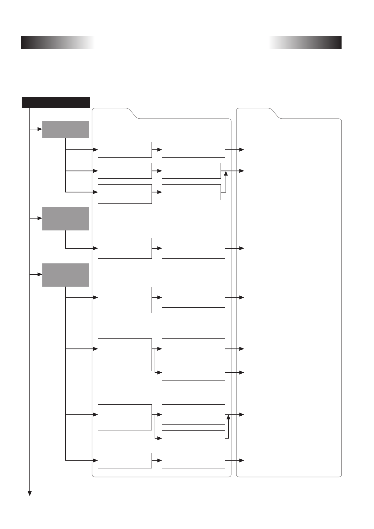
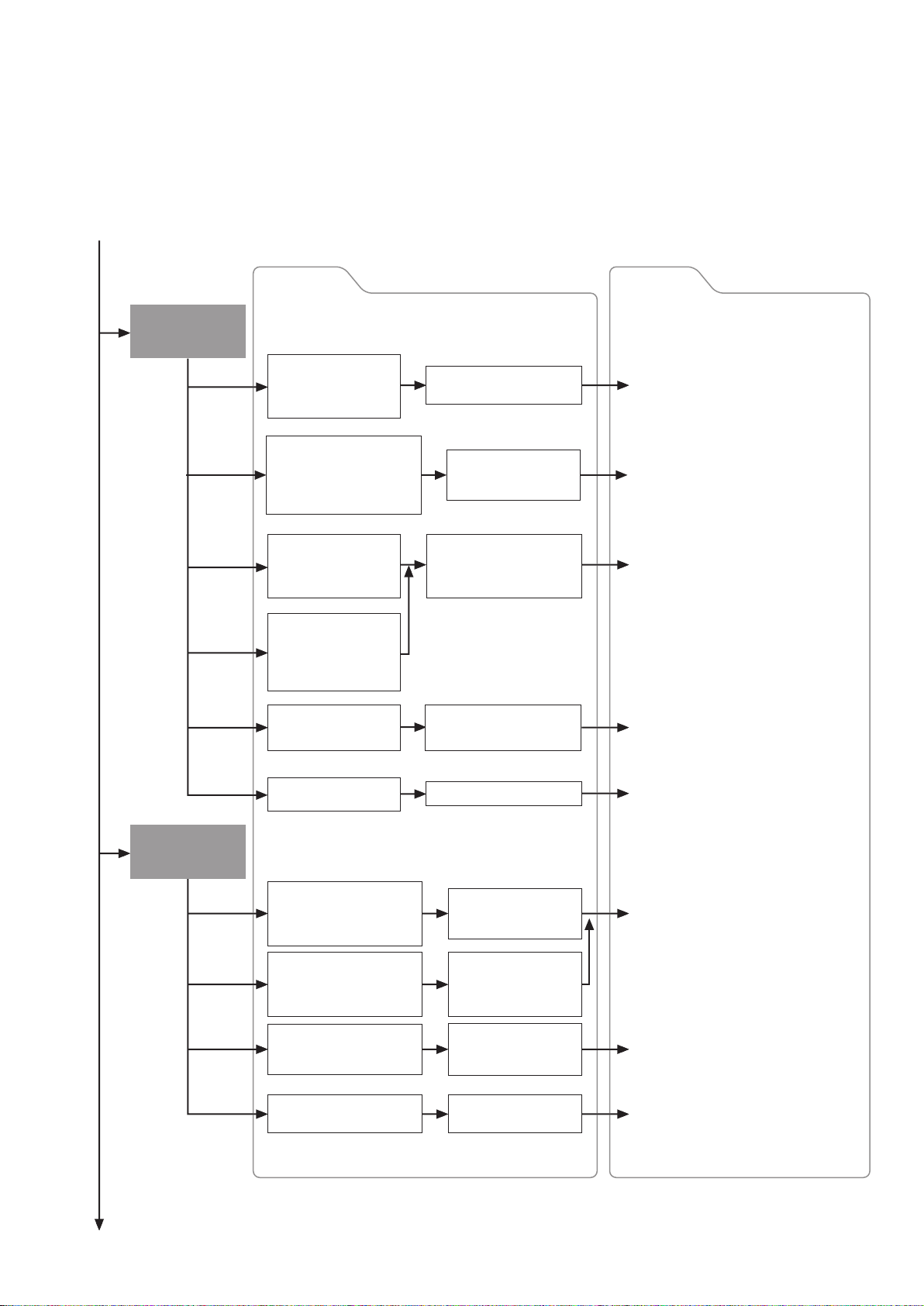
Replacement Options and
Module Selection Guide
Specific modules are selected according to the transition procedure (gradually or simultaneously), module
configuration, and network configuration when replacing A/QnA (Large Type), AnS/QnAs (Small Type) Series
modules with Q/L Series modules.
The following shows module replacement options and references.
Module replacement
Replacing
A0J2HCPU
Modifying/Replacing
A (Large Type)
Series modules
Replacing
A (Large Type) Series
with Q Series
Options
To utilize existing
wiring
To replace with
Q Series I/O modules
To replace special
function modules with
Q Series modules
To add modules
to existing A (Large
Type) Series system
To only replace the CPU
module and continue using
existing A (Large Type)
Series modules
Use A0J2 renewal tool
manufactured by SC*
Select Q Series I/O
modules
Select Q Series modules
Modify/Replace modules
using A-A1S module
conversion adapter (A1ADP)
Replace modules using QA
extension base unit and
QA conversion adapter
1
References
Example: Section 2.4
Replace A0J2(H) systems with Q Series
using existing wiring
Transition from MELSEC-A0J2H Series
to Q Series Handbook
(L-08060ENG)
Example: Section 6.1
Use AnS (Small Type) modules as spare
parts for existing A (Large Type) Series
Example: Section 3.1.1
Utilize A/QnA (Large Type) Series QA6�B
extension base unit
Example: Section 3.1.2
Utilize existing I/O modules and extension
base unit with Q Series CPU
(Use QA conversion adapter)
To replace A (Large Type)
Series 32-point terminal
block type modules
without changing the
wiring configuration
To replace modules
when it is difficult to
use the Q Series
large type base unit
To replace all modules
with Q Series modules
*1: SC: Mitsubishi Electric System & Service Co., Ltd.
*2: MEE: Mitsubishi Electric Engineering Co., Ltd.
Artisan Technology Group - Quality Instrumentation ... Guaranteed | (888) 88-SOURCE | www.artisantg.com
Replace modules using
Q Series large type base unit
and I/O modules
Replace modules using upgrade
tool manufactured by MEE*
Replace modules using
terminal block converter
module and terminal module
Replace modules using FA
goods manufactured by MEE*
Select Q Series modules
2
2
18
Example: Section 2.1.2
Upgrade to Q Series using Q Series large
type base unit and I/O modules
Example: Section 2.1.3
Upgrade to Q Series using Q Series large
type base unit and I/O modules
Example: Section 2.1.2 (2)
Compatibility of Q Series large type
base unit with the upgrade tool
Example: Section 2.1.1
Install terminal block converter module
and terminal module externally
Transition from MELSEC-A/QnA
(Large Type) Series to Q Series
Handbook (Fundamentals)
(L-08043ENG)
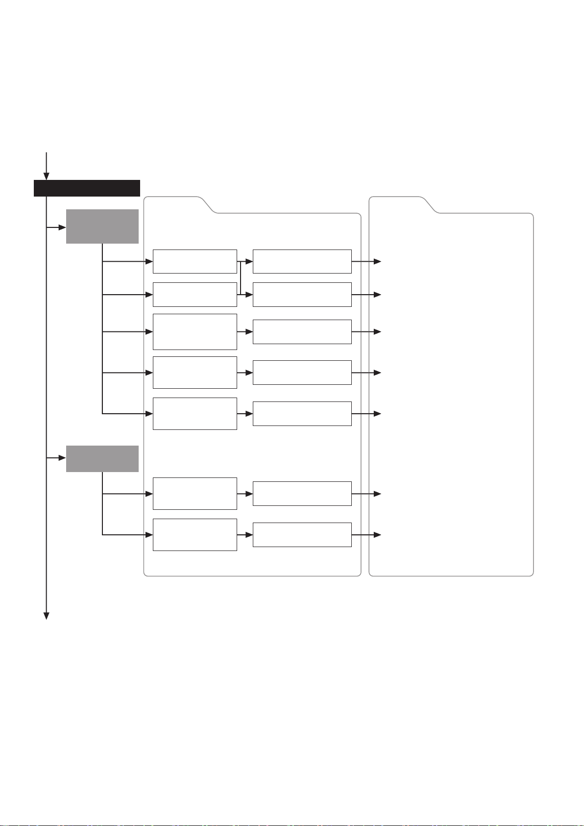
Replacing AnS
(Small Type) Series
with Q Series
Options References
To only replace the CPU
module and continue
using the existing AnS
(Small Type) module
Replace modules using
QA1S extension base
Example: Section 3.2.1
Utilize AnS/QnAS (Small Type) Series
QA1S6�B extension base unit
Replacing AnS
(Small Type) Series
with L Series
To replace only the modules
in the main base unit and
continue using the existing
AnS (Small Type) modules
in the extension base unit
To mount Q Series base
unit using existing AnS
(Small Type) base unit
mounting holes
To replace existing AnS
(Small Type) 16-point
terminal block module
without changing the
wiring configuration
To replace modules when
it is difficult to use the Q
Series large type base unit
To replace all modules
with Q Series modules
To install L Series DIN rail
using existing AnS (Small
Type) base unit mounting
holes
Replace modules
using Q-Ans base unit
conversion adapter
Replace modules using
AnS (Small Type) Series
upgrade tool manufactured
by MEE*
Replace modules using FA
goods manufactured by
MEE*
Select Q Series modules
Use base adapter
integrated with DIN
rail
Example: Item 3.2.2
Replace main base unit with Q Series
and use existing extension base unit and
modules in it
(Use QA1S conversion adapter)
Example: Section 2.2.2
Utilize AnS/QnAS (Small Type) module
replacement upgrade tool
Example: Section 2.2.3
Replace AnS/QnAS (Small Type) Series
200 V AC input module A1SX20
[Use FA goods (manufactured by
Mitsubishi Electric Engineering Co., Ltd.)]
Transition from MELSEC-AnS/QnAS
(Small Type) Series to Q Series Handbook
(Fundamentals) (L(NA)08219ENG)
Example: Item 2.3.1
Replace using upgrade tool for replacing
with L Series
To replace existing AnS (Small
Type) 16-point terminal block
type modules without changing
the wiring configuration
To obtain information on
tools other than the
upgrade tool
To replace all modules
with L Series modules
*: MEE: Mitsubishi Electric Engineering Co., Ltd.
Artisan Technology Group - Quality Instrumentation ... Guaranteed | (888) 88-SOURCE | www.artisantg.com
Replace modules using
AnS (Small Type) Series
upgrade tool manufactured by MEE*
Replace modules using
FA goods manufactured
by MEE*
Select L Series
modules
19
Example: Item 2.3.2
Replace AnS/QnAS (Small Type) Series
200 V AC input module A1SX20
[Use FA goods (manufactured by
Mitsubishi Electric Engineering Co.,
Ltd.)]
Transition from MELSEC-AnS/QnAS
(Small Type) Series to L Series
Handbook (Fundamentals)
(L(NA)08258ENG)
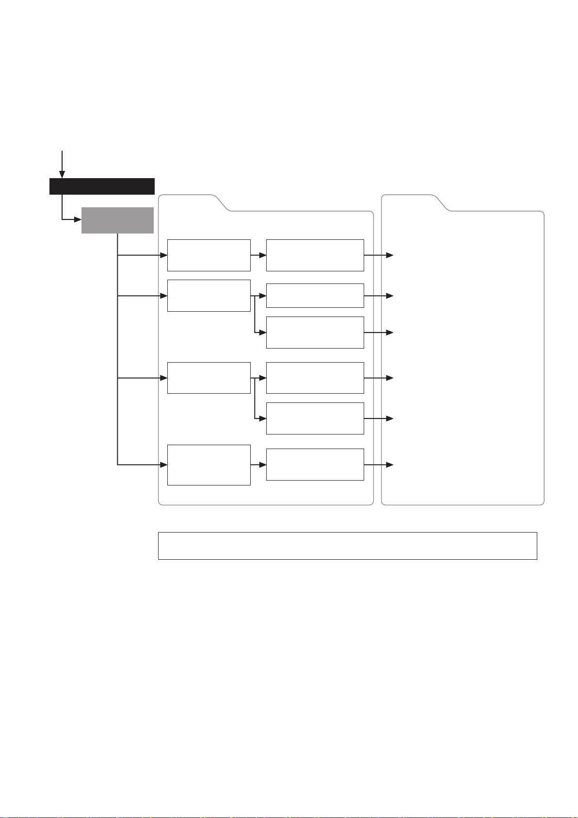
Network replacement
Replacing
MELSECNET/MINI
(S3) with CC-Link
Replacing
Replacing
MELSECNET(ΙΙ)
MELSEC-I/OLINK
Options References
To replace networks using
existing external wiring
To replace A2CCPU
To replace networks
when it is difficult to
use existing wiring
configuration
To replace
compact type remote
I/O modules
To replace building
block type remote
I/O modules
To replace networks
without changing
existing addresses
Replace network using A2C
shape I/O modules
Replace network using
wiring conversion adapter
Select CC-Link modules
Use A0J2 renewal tool
manufactured by SC*
Replace with MELSECNET/H
remote I/O network
Replace with CC-Link/LT
Example: Section 4.5.1
Replace A2CCPU with Q Series CPU
and CC-Link
Example: Section 4.5.2
Replace MELSECNET/MINI(-S3) with
CC-Link
Transition from MELSECNET/MINI-S3,
A2C(I/O) to CC-Link Handbook
(L-08061ENG)
Example: Section 2.4.3
Replace MELSECNET/MINI compact type
remote I/O modules with CC-Link
Example: Section 4.5.3
Replace MELSECNET/MINI(-S3) remote
I/O station with MELSECNET/H using the
existing external wiring
Example: Section 4.6
Replace MELSEC-I/OLINK with CC-Link/LT,
AnyWire DB A20
To replace networks
using existing
communication cables
*: SC: Mitsubishi Electric System & Service Co., Ltd.
Replace with AnyWire
DB A20
Example: Section 4.6
Replace MELSEC-I/OLINK with CC-Link/LT,
AnyWire DB A20
Artisan Technology Group - Quality Instrumentation ... Guaranteed | (888) 88-SOURCE | www.artisantg.com
20
Network replacement
Replacing
MELSECNET(ΙΙ)
Options References
To replace CPU modules
while retaining the existing
MELSECNET(ΙΙ)
To replace with
MELSECNET/10 using
existing cables
To replace networks
containing a remote
I/O station
To gradually replace
networks using existing
MELSECNET(ΙΙ) and
MELSECNET/10
Replace modules using
MELSECNET(ΙΙ) local station
data link modules
Upgrade gradually to
Q Series CPU modules
Transition to MELSECNET/H
using MELSECNET/B twisted
pair cables
Replace networks using
MELSECNET/H PLC to PLC
network and remote I/O network
Change from remote I/O station
to normal station and replace
as one single network
Use a gateway set to
configure networks with
relay stations
Example: Section 4.2
Replace one of A Series stations with
Q Series while retaining MELSECNET(ΙΙ)
Example: Section 4.1.1
Replace MELSECNET(ΙΙ) coaxial loop
with MELSECNET/10 coaxial bus system
while retaining existing A Series CPUs
Example: Section 4.1.2
Upgrade to MELSECNET/H network
system utilizing existing MELSECNET/B
twisted pair cable
Transition from MELSEC-A/QnA
(Large Type) Series to Q Series
Handbook (Network Modules)
(L-08048ENG)
Example: Chapter 4.3
Replace MELSECNET containing a remote
I/O station with MELSECNET/H
Transition from MELSEC-A/QnA
(Large Type) Series to Q Series
Handbook (Network Modules)
(L-08048ENG)
This section describes the main replacement options. If multiple options are selected or other options
are needed, comprehensive consideration is required to configure the system.
Artisan Technology Group - Quality Instrumentation ... Guaranteed | (888) 88-SOURCE | www.artisantg.com
21

MEMO
Artisan Technology Group - Quality Instrumentation ... Guaranteed | (888) 88-SOURCE | www.artisantg.com
22

PartⅠ: Hardware
Artisan Technology Group - Quality Instrumentation ... Guaranteed | (888) 88-SOURCE | www.artisantg.com
23
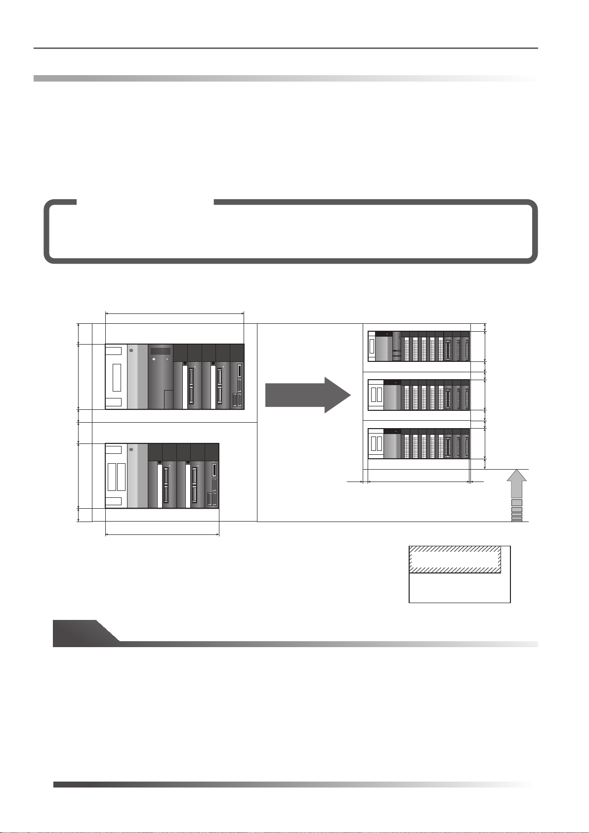
1.1 Comparison of A/QnA (Large Type) Series and Q Series base unit mounting area
Comparison of base mounting area
1.
1.1 Comparison of A/QnA (Large Type) Series and Q Series base unit mounting area
When upgrading existing A/QnA systems, there are cases where the number of modules increases due to
specification differences. For instance, to replace an A/QnA (Large Type) Series 32-point terminal block type I/O
module, two Q Series 16-point terminal block type I/O modules are used. Despite increase in the number of I/O
slots and extension base stages, the Q Series footprint is smaller than that of the A/QnA (Large Type) Series.
The following example shows a comparison of the mounting areas when the A/QnA (Large Type) Series system
is upgraded to the Q Series.
Solution and Benefit
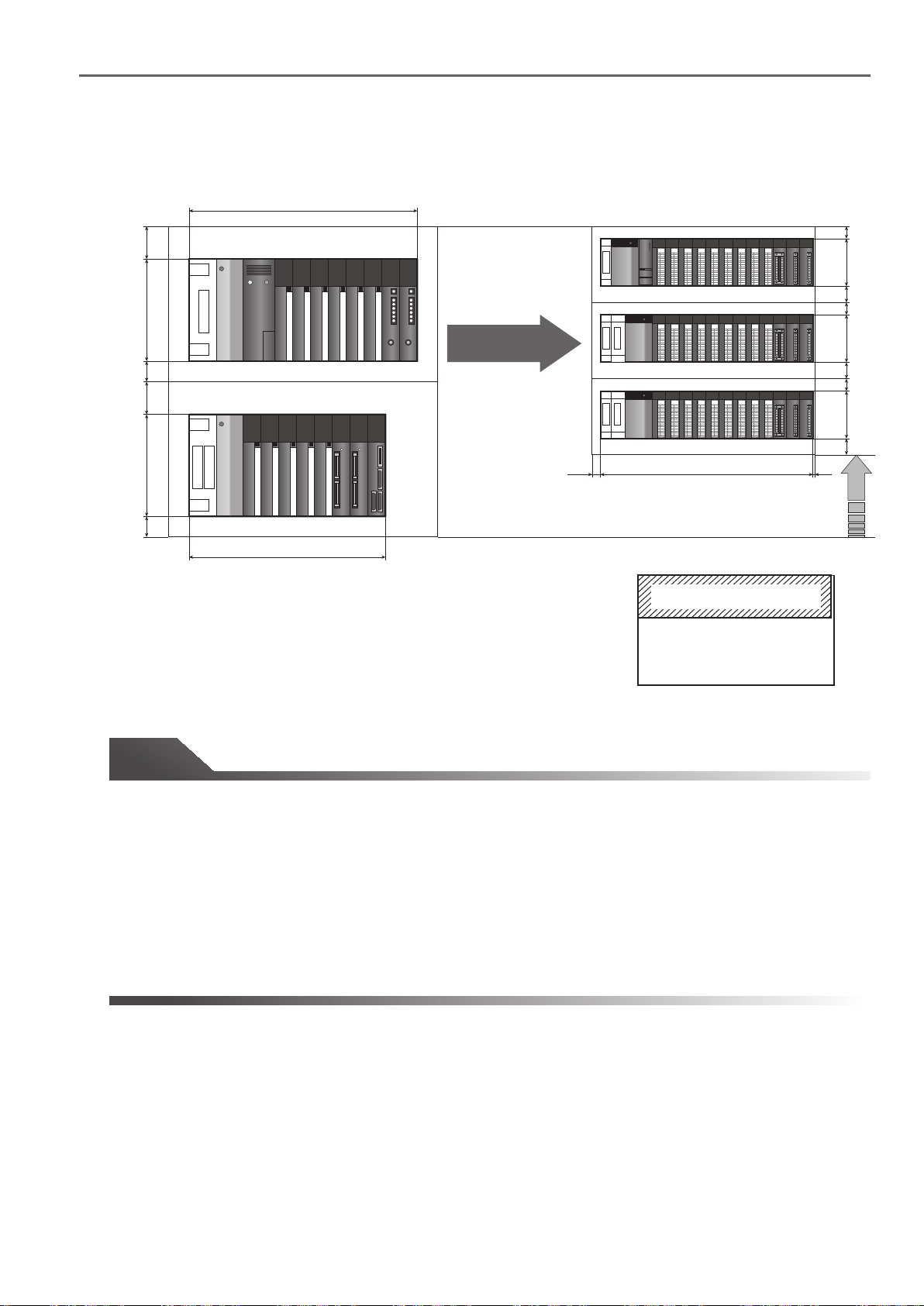
When replacing each 32-point terminal block type module with two 16-point terminal block type
modules, an additional extension base unit is required due to an increase in the number of modules.
However, the Q Series system fits inside the existing control panel because it is compact in size.
(1) When the A/QnA (Large Type) Series main base unit A35B and the A65B extension base unit are
replaced
250
250
382
80
A35B
Q38B/Q68B
0
0
0
0
1
1
1
1
2
2
2
2
3
3
3
3
4
4
4
4
5
5
5
5
6
6
6
6
7
7
7
7
8
8
8
8
9
9
9
9
A
A
A
A
B
B
B
B
C
C
C
C
D
D
D
D
E
E
E
E
F
F
F
F
30
0
1
2
3
4
5
6
7
8
9
A
B
C
D
E
F
98
40
30
0
0
0
0
1
2
3
4
5
6
7
Replace
8
9
A
B
C
D
E
F
50
0
1
1
1
1
2
2
2
2
3
3
3
3
4
4
4
4
5
5
5
5
6
6
6
6
7
7
7
7
8
8
8
8
9
9
9
9
A
A
A
A
B
B
B
B
C
C
C
C
D
D
D
D
E
E
E
E
F
F
F
F
98
40
30
80
A65B
0
0
0
0
1
2
3
4
5
6
7
8
9
A
B
C
D
E
F
0
1
1
1
1
2
2
2
2
3
3
3
3
4
4
4
4
5
5
5
5
6
6
6
6
7
7
7
7
8
8
8
8
9
9
9
9
A
A
A
A
B
B
B
B
C
C
C
C
D
D
D
D
E
E
E
E
F
F
F
F
98
40
20 5
50
352
328
Downsized
Unit: mm
Q38B/Q68B
A35B
Base unit size comparsion
Tip
The A/QnA (Large Type) Series main base unit and extension base unit differ in size:
• A35B main base unit: 382 mm (W) x 250 mm (H)
• A65B extension base unit: 352 mm (W) x 250 mm (H)
Whereas the Q Series main base unit and extension base unit are the same size:
• Q38B main base unit/Q68B extension base unit: 328 mm (W) x 98 mm (H)
Even with the extra I/O slots and base units, the base unit installation area for Q Series is smaller than that for
A/QnA (Large Type) Series.
Artisan Technology Group - Quality Instrumentation ... Guaranteed | (888) 88-SOURCE | www.artisantg.com
24
1.1 Comparison of A/QnA (Large Type) Series and Q Series base unit mounting area
(2) When the A/QnA (Large Type) Series main base unit A38B and the A68B extension base unit are
replaced
250
250
480
80
A38B
Q312B/Q612B
0
0
0
0
0
0
1
1
1
2
2
2
3
3
3
4
4
4
5
5
5
6
6
6
7
7
7
8
8
8
9
9
9
A
A
A
B
B
B
C
C
C
D
D
D
E
E
E
F
F
F
0
1
1
1
1
2
2
2
2
3
3
3
3
4
4
4
4
5
5
5
5
6
6
6
6
7
7
7
7
8
8
8
8
9
9
9
9
A
A
A
A
B
B
B
B
C
C
C
C
D
D
D
D
E
E
E
E
F
F
F
F
30
0
0
1
1
2
2
3
3
4
4
5
5
6
6
7
7
8
8
9
9
A
A
B
B
C
C
D
D
E
E
F
F
98
40
30
0
0
0
0
0
0
0
0
1
1
1
1
1
2
2
2
2
2
3
3
3
3
3
4
4
4
4
4
5
5
5
5
5
6
6
6
6
6
7
7
7
7
7
8
8
8
8
8
9
9
9
9
9
A
A
A
A
Replace
B
C
D
E
F
A
B
B
B
B
C
C
C
C
D
D
D
D
E
E
E
E
F
F
F
F
50
0
1
1
1
1
2
2
2
2
3
3
3
3
4
4
4
4
5
5
5
5
6
6
6
6
7
7
7
7
8
8
8
8
9
9
9
9
A
A
A
A
B
B
B
B
C
C
C
C
D
D
D
D
E
E
E
E
F
F
F
F
98
40
30
80
A68B
0
0
0
0
0
0
0
0
1
1
1
1
1
2
2
2
2
2
3
3
3
3
3
4
4
4
4
4
5
5
5
5
5
6
6
6
6
6
7
7
7
7
7
8
8
8
8
8
9
9
9
9
9
A
A
A
A
A
B
B
B
B
B
C
C
C
C
C
D
D
D
D
D
E
E
E
E
E
F
F
F
F
F
0
1
1
1
1
2
2
2
2
3
3
3
3
4
4
4
4
5
5
5
5
6
6
6
6
7
7
7
7
8
8
8
8
9
9
9
9
A
A
A
A
B
B
B
B
C
C
C
C
D
D
D
D
E
E
E
E
F
F
F
F
98
40
20
50
466
439 5
Downsized
Unit: mm
Q312B/Q612B
A38B
Base unit size comparsion
Tip
The A/QnA (Large Type) Series main base unit and extension base unit differ in size:
• A38B main base unit: 480 mm (W) x 250 mm (H)
• A68B extension base unit: 466 mm (W) x 250 mm (H)
Whereas the Q Series main base unit and extension base unit are the same size:
• Q312B main base unit/Q612B extension base unit: 439 mm (W) x 98 mm (H)
Even with the extra I/O slots and base units, the base unit installation area for Q Series is smaller than that for
A/QnA (Large Type) Series.
Artisan Technology Group - Quality Instrumentation ... Guaranteed | (888) 88-SOURCE | www.artisantg.com
25
1.2 Comparison of AnS/QnAS (Small Type) Series and Q Series base unit mounting area
1.2 Comparison of AnS/QnAS (Small Type) Series and Q Series base unit mounting area
The Q Series is compact, and has a smaller mounting area.
It can be mounted within the AnS/QnAS (Small Type) mounting area.
The following example shows a comparison of the mounting areas when the AnS/QnAS (Small Type) Series
system is upgraded to the Q Series.
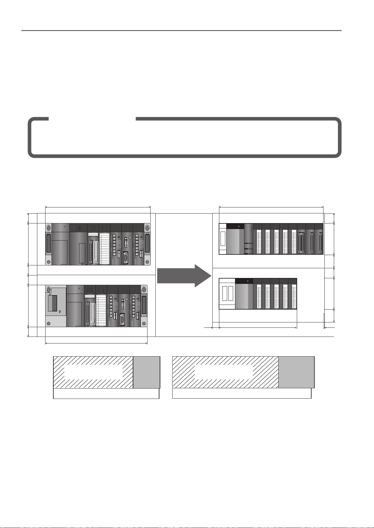
Solution and Benefit
Using the “AnS to Q Series conversion adapter” (manufactured by Mitsubishi Electric Engineering
Co., Ltd.), the 16-point terminal block type module can fit into the existing space without changing
the wiring.
(1) When the AnS/QnAS (Small Type) Series main base unit A1S35B and the A1S65B extension base
unit are replaced
30
130
30
30
130
30
325
A1S35B
A1S65B
315
Q35B/Q65B Q38B/Q68B
Q38B
/Q68B
Replace
328
Q38B/Q68B
0
0
0
0
1
1
2
2
3
3
4
4
5
5
6
6
7
7
8
8
9
9
A
A
B
B
C
C
D
D
E
E
F
F
0
1
1
1
2
2
2
3
3
3
4
4
4
5
5
5
6
6
6
7
7
7
8
8
8
9
9
9
A
A
A
B
B
B
C
C
C
D
D
D
E
E
E
F
F
F
Q35B/Q65B
0
0
0
0
1
1
2
2
3
3
4
4
5
5
6
6
7
7
8
8
9
9
A
A
B
B
C
C
D
D
E
E
F
F
0
1
1
1
2
2
2
3
3
3
4
4
4
5
5
5
6
6
6
7
7
7
8
8
8
9
9
9
A
A
A
B
B
B
C
C
C
D
D
D
E
E
E
F
F
F
24520 5
Q312B
/Q612B
30
98
40
30
98
40
Unit: mm
A1S38BA1S35B
Base unit size comparsion
Artisan Technology Group - Quality Instrumentation ... Guaranteed | (888) 88-SOURCE | www.artisantg.com
26
1.2 Comparison of AnS/QnAS (Small Type) Series and Q Series base unit mounting area
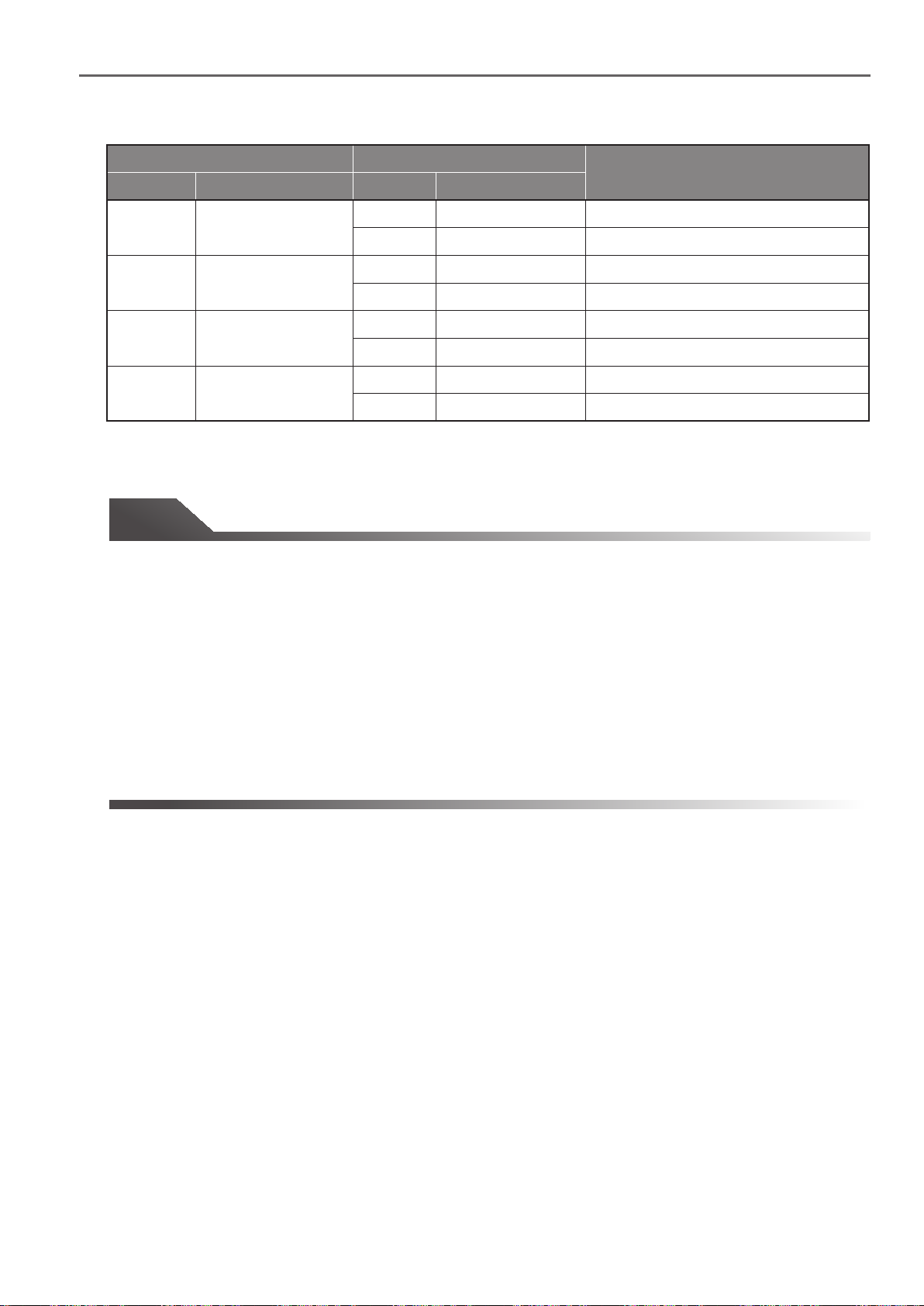
Existing base unit Replacement base unit
Model Outline dimensions Outline dimensionsModel
A1S35B
A1S38B
A1S65B
A1S68B
325(W)×130(H)
430(W)×130(H)
315(W)×130(H)
420(W)×130(H)
Q35B
Q38B
Q38B
Q312B
Q65B
Q68B
Q68B
Q612B
245(W)×98(H)
328(W)×98(H)
328(W)×98(H)
439(W)×98(H)
245(W)×98(H)
328(W)×98(H)
328(W)×98(H)
439(W)×98(H)
Width is 80 mm narrower
Width is 3 mm wider
Width is 102 mm narrower
Width is 9 mm wider
Width is 70 mm narrower
Width is 13 mm wider
Width is 92 mm narrower
Width is 19 mm wider
Tip
The AnS /QnA (Small Type) Series main base unit and extension base unit differ in size:
• A1S35B main base unit: 325 mm (W) x 130 mm (H)
• A1S65B extension base unit: 315 mm (W) x 130 mm (H)
Remarks
Whereas the Q Series main base unit and extension base unit are the same size:
• Q38B main base unit/Q68B extension base unit: 328 mm (W) x 98 mm (H)
The width will increase if the number of modules increases, i.e., A1S35B to Q68B will increase 3 mm, and
A1S38B to Q312B will increase by 9 mm.
However, this increase can be handled. Confirm the in-panel layout and space and determine whether the
extra modules can be mounted.
Artisan Technology Group - Quality Instrumentation ... Guaranteed | (888) 88-SOURCE | www.artisantg.com
27
 Loading...