

Mitsubishi Electric Artisan MELSEC-Q, Artisan MELSEC-A, Artisan MELSEC-QnA, Artisan MELSEC-AnS, Artisan MELSEC-QnAS Series Manual
...Page 1

Artisan Technology Group is your source for quality
new and certied-used/pre-owned equipment
• FAST SHIPPING AND
DELIVERY
• TENS OF THOUSANDS OF
IN-STOCK ITEMS
• EQUIPMENT DEMOS
• HUNDREDS OF
MANUFACTURERS
SUPPORTED
• LEASING/MONTHLY
RENTALS
• ITAR CERTIFIED
SECURE ASSET SOLUTIONS
SERVICE CENTER REPAIRS
Experienced engineers and technicians on staff
at our full-service, in-house repair center
Instra
Remotely inspect equipment before purchasing with
our interactive website at www.instraview.com
Contact us: (888) 88-SOURCE | sales@artisantg.com | www.artisantg.com
SM
REMOTE INSPECTION
View
WE BUY USED EQUIPMENT
Sell your excess, underutilized, and idle used equipment
We also offer credit for buy-backs and trade-ins
www.artisantg.com/WeBuyEquipment
LOOKING FOR MORE INFORMATION?
Visit us on the web at www.artisantg.com for more
information on price quotations, drivers, technical
specications, manuals, and documentation
Page 2
Mitsubishi General-purpose Programmable Controllers
MELSEC-A/QnA (Large), AnS/QnAS (Small)
Transition Examples
Dec. 2014 Edition
Artisan Technology Group - Quality Instrumentation ... Guaranteed | (888) 88-SOURCE | www.artisantg.com
Page 3

Under some circumstances, failure to observe the precautions given under " CAUTION" may lead
to serious consequences.
Observe the precautions of both levels because they are important for personal and system safety.
Make sure that the end users read this publication and keep it in a safe place for future reference.
Before using products introduced in this publication, please read this Transition
Examples and relevant manuals carefully and pay full attention to safety to handle
the product correctly.
In this publication, the safety precautions are classified into two levels:
" WARNING" and " CAUTION".
CAUTION
WARNING
Indicates that incorrect handling may cause hazardous conditions,
resulting in death or severe injury.
Indicates that incorrect handling may cause hazardous conditions,
resulting in minor or moderate injury or property damage.
● Configure safety circuits external to the programmable controller to ensure that the entire system operates
safely even when a fault occurs in the external power supply or the programmable controller. Failure to do
so may result in an accident due to an incorrect output or malfunction.
(1) Configure external safety circuits, such as an emergency stop circuit, protection circuit, and protective
interlock circuit for forward/reverse operation or upper/lower limit positioning.
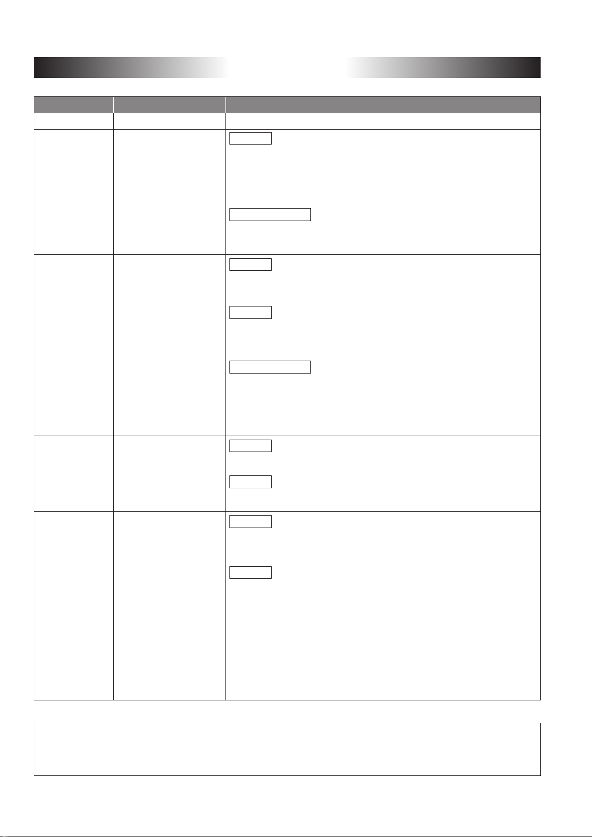
(2) The programmable controller stops its operation upon detection of the following status, and the output
status of the system will be as shown below.
All outputs may turn on when an error occurs in the part, such as I/O control part, where the CPU module
cannot detect any error. To ensure safety operation in such a case, provide a safety mechanism or a
fail-safe circuit external to the programmable controller. For a fail-safe circuit example, refer to LOADING
AND INSTALLATION in the QCPU User's Manual (Hardware Design, Maintenance and Inspection).
(3) Outputs may remain on or off due to a failure of an output module relay or transistor. Configure an
external circuit for monitoring output signals that could cause a serious accident.
Q Series ModuleStatus
All out puts are turned off.
A/AnS Series module
All out puts are turned off.
All out puts are turned off.
Overcurrent or overvoltage protection of
the power supply module is activated.
The CPU module detects an error such as
a watchdog timer error by the self-diagnostic
function.
All outputs are held or turned
off according to the parameter
setting.
WARNING
Artisan Technology Group - Quality Instrumentation ... Guaranteed | (888) 88-SOURCE | www.artisantg.com
Page 4
Safety Precautions
● When replacing A (Large Type)/AnS (Small Type) Series with Q Series ●
Before using products introduced in this publication, please read this Transition
Examples and relevant manuals carefully and pay full attention to safety to handle
the product correctly.
In this publication, the safety precautions are classified into two levels:
" WARNING" and " CAUTION".
Indicates that incorrect handling may cause hazardous conditions,
WARNING
CAUTION
Under some circumstances, failure to observe the precautions given under " CAUTION" may lead
to serious consequences.
Observe the precautions of both levels because they are important for personal and system safety.
resulting in death or severe injury.
Indicates that incorrect handling may cause hazardous conditions,
resulting in minor or moderate injury or property damage.
Make sure that the end users read this publication and keep it in a safe place for future reference.
Design Precautions
WARNING
● Configure safety circuits external to the programmable controller to ensure that the entire system operates
safely even when a fault occurs in the external power supply or the programmable controller. Failure to do
so may result in an accident due to an incorrect output or malfunction.
(1) Configure external safety circuits, such as an emergency stop circuit, protection circuit, and protective
interlock circuit for forward/reverse operation or upper/lower limit positioning.
(2) The programmable controller stops its operation upon detection of the following status, and the output
status of the system will be as shown below.
Overcurrent or overvoltage protection of
the power supply module is activated.
The CPU module detects an error such as
a watchdog timer error by the self-diagnostic
function.
Q Series ModuleStatus
All out puts are turned off.
All outputs are held or turned
off according to the parameter
setting.
A/AnS Series module
All out puts are turned off.
All out puts are turned off.
All outputs may turn on when an error occurs in the part, such as I/O control part, where the CPU module
cannot detect any error. To ensure safety operation in such a case, provide a safety mechanism or a
fail-safe circuit external to the programmable controller. For a fail-safe circuit example, refer to LOADING
AND INSTALLATION in the QCPU User's Manual (Hardware Design, Maintenance and Inspection).
(3) Outputs may remain on or off due to a failure of an output module relay or transistor. Configure an
external circuit for monitoring output signals that could cause a serious accident.
Artisan Technology Group - Quality Instrumentation ... Guaranteed | (888) 88-SOURCE | www.artisantg.com
1
Page 5
Design Precautions
WARNING
● In an output module, when a load current exceeding the rated current or an overcurrent caused by a load
short-circuit flows for a long time, it may cause smoke and fire. To prevent this, configure an external safety
circuit, such as a fuse.
● Configure a circuit so that the programmable controller is turned on first and then the external power supply.
If the external power supply is turned on first, an accident may occur due to an incorrect output or
malfunction.
● For the operating status of each station after a communication failure, refer to relevant manuals for the
network.
Incorrect output or malfunction due to a communication failure may result in an accident.
● When controlling (changing data) the running programmable controller from a peripheral connected to the
CPU module or from a personal computer connected to an intelligent function module, configure an interlock
circuit in the sequence program to ensure that the entire system will always operate safely.
For other controls for the running programmable controller (program modification and operating status
change (status control)), read relevant manuals carefully, and ensure the safety before operation.
Especially, in the case of a control from an external device to a remote programmable controller, immediate
action cannot be taken for a problem on the programmable controller due to a communication failure.
Configure an interlock circuit in the sequence program, and determine corrective actions to be taken
between the external device and CPU module in case of a communication failure.
CAUTION
● Do not install the control lines or communication cables together with the main circuit lines or power cables.
Keep a distance of 100mm (3.94 inches) or more between them.
Failure to do so may result in malfunction due to noise.
● When a device such as a lamp, heater, or solenoid valve is controlled through an output module, a large
current (approximately ten times greater than normal) may flow when the output is turned from off to on.
Take measures such as replacing the module with one having a sufficient current rating.
● The time for the CPU module to enter the RUN status after the CPU module is powered off and on or reset
will vary depending on the system configuration, parameter settings, and/or program size, etc.
Design the program so that the entire system will operate safely even if the time to reach the RUN status
varies.
Artisan Technology Group - Quality Instrumentation ... Guaranteed | (888) 88-SOURCE | www.artisantg.com
2
Page 6

Installation Precautions
CAUTION
● Use the programmable controller in an environment that meets the general specifications in the QCPU
User's Manual (Hardware Design, Maintenance and Inspection).
Failure to do so may result in electric shock, fire, malfunction, or damage to or deterioration of the product.
● To mount the module, while pressing the module mounting lever located in the lower part of the module, fully
insert the module fixing projection(s) into the hole(s) in the base unit and press the module until it snaps into
place.
Incorrect mounting may cause malfunction, failure or drop of the module.
When using the programmable controller in an environment of frequent vibrations, fix the module with a
screw.
Tighten the screw within the specified torque range.
Undertightening can cause drop of the screw, short circuit or malfunction.
Overtightening can damage the screw and/or module, resulting in drop, short circuit, or malfunction.
● When using an extension cable, connect it to the extension cable connector of the base unit securely.
Check the connection for looseness.
Poor contact may cause incorrect input or output.
● When using an SD memory card, fully insert it into the SD memory card slot.
Check that it is inserted completely.
Poor contact may cause malfunction.
● When using an extended SRAM cassette, fully insert it into the cassette connector on the CPU module.
Close the cassette cover to keep the extended SRAM cassette inserted completely.
Poor contact may cause malfunction.
● Shut off the external power supply for the system in all phases before mounting or removing the module.
Failure to do so may result in damage to the product.
A module can be replaced online (while power is on) on any MELSECNET/H remote I/O station or in the
system where a CPU module supporting the online module change function is used.
Note that there are restrictions on the modules that can be replaced online, and each module has its
predetermined replacement procedure.
For details, refer to the relevant sections in the QCPU User's Manual (Hardware Design, Maintenance and
Inspection) and in the manual for the corresponding module.
● Do not directly touch any conductive part or electronic component of the module, memory card, SD memory
card or extended SRAM cassette. Doing so can cause malfunction or failure.
● When using a motion CPU module and a motion module, make sure that proper modules are combined
before turning on power. If improper modules are used, they may be damaged. For details, refer to the
Motion CPU Module User's Manual.
Artisan Technology Group - Quality Instrumentation ... Guaranteed | (888) 88-SOURCE | www.artisantg.com
3
Page 7
Wiring Precautions
WARNING
● Shut off the external power supply for the system in all phases before mounting or wiring the module.
Failure to do so may result in electric shock or damage to the product.
● After mounting or wiring, attach the included terminal cover onto the module before turning the power on or
starting operation.
Failure to do so may result in electric shock.
CAUTION
● Ground the FG and LG terminals to the dedicated conductors for the programmable controller (Class D
(Class 3) or higher grounding).
Failure to do so may result in electric shock or malfunction.
● Use applicable solderless terminals and tighten them within the specified torque range.
If any spade solderless terminal is used, it may be disconnected when the terminal screw comes loose,
resulting in failure.
● Check the rated voltage and terminal layout before wiring to the module, and connect the cables correctly.
Inputting voltage different from the rated voltage, connecting a power supply with a different voltage rating or
incorrect wiring may cause a fire or failure.
● Connectors for external connection must be crimped or pressed with the tool specified by the manufacturer,
or must be correctly soldered.
Incomplete connections could result in short circuit, fire, or malfunction.
● Fit the connectors surely to the module. Poor contact may cause malfunction.
● Do not bundle the control cable or communication cable with the main circuit or power wire, or lay them
adjacently.
Separate these by 100 mm or more.
Failure to observe this could lead to malfunctioning caused by noise.
● When connecting any cable, check the type of the interface to be connected.
Connecting to an improper interface or incorrect wiring may damage the module and external devices.
● Tightening the terminal screws within the specified torque range.
Under tightening the terminal screws can cause short circuit, a fire or malfunction.
Overtightening can damage the screw and/or module, resulting in drop, short circuit, or malfunction.
● Prevent foreign matter such as dust or wire chips from entering the module.
Such foreign matter can cause a fire, failure, or malfunction.
● A protective film is attached to the top of the module to prevent foreign matter, such as wire chips, from
entering the module during wiring.
Do not remove the film during wiring.
Remove it for heat dissipation before system operation.
● When disconnecting any cable from the module, do not pull the cable.
When disconnecting a cable with a connector, hold the connector of the connecting part of the module.
Before disconnecting a cable from the terminal block, loosen the terminal screw on the terminal block.
Pulling the cable with the terminal connected to the module may cause malfunction or damage to the
module or cable.
● Mitsubishi programmable controllers must be installed in control panels.
Connect the main power supply to the power supply module in the control panel through a relay terminal
block.
Wiring and replacement of a power supply module must be performed by maintenance personnel who is
familiar with protection against electric shock. (For wiring methods, refer to the QCPU User's Manual
(Hardware Design, Maintenance and Inspection)).
Artisan Technology Group - Quality Instrumentation ... Guaranteed | (888) 88-SOURCE | www.artisantg.com
4
Page 8
Startup and Maintenance Precautions
WARNING
● Do not touch any terminal while power is on.
Doing so will cause electric shock.
● Correctly connect the battery connector.
The battery must not be charged, disassembled, heated, thrown into the fire, short-circuited, soldered,
wetted with a liquid or exposed to strong shock.
Doing so will cause the battery to produce heat, explode, or ignite, resulting in injury and fire.
● Shut off the external power supply for the system in all phases before cleaning the module or retightening
the terminal screws or module fixing screws.
Failure to do so may result in electric shock, damage to the module and malfunction.
CAUTION
● Before performing online operations (especially, program modification, forced output, and operation status
change) for the running CPU module from the peripheral connected, read relevant manuals carefully and
ensure the safety.
Improper operation may damage machines or cause accidents.
● Do not disassemble or modify the modules.
Doing so may cause failure, malfunction, injury, or a fire.
● Use any radio communication device such as a cellular phone or PHS (Personal Handy-phone System)
more than 25cm (9.85 inches) away in all directions from the programmable controller.
Failure to do so may cause malfunction.
● Shut off the external power supply for the system in all phases before mounting or removing the module.
Failure to do so may cause the module to fail or malfunction.
A module can be replaced online (while power is on) on any MELSECNET/H remote I/O station or in the
system where a CPU module supporting the online module change function is used.
Note that there are restrictions on the modules that can be replaced online, and each module has its
predetermined replacement procedure.
For details, refer to the relevant sections in the QCPU User's Manual (Hardware Design, Maintenance and
Inspection) and in the manual for the corresponding module.
● Connection/disconnection of the module to/from the base unit and the extended SRAM cassette and
terminal block to/from the CPU module after the first use of the product shall be limited to 50 times.
(Compliant with JIS B 3502)
Exceeding the limit of 50 times may cause malfunction.
● Connection/disconnection of the SD memory card after the first use of the product shall be limited to 500
times. Exceeding the limit of 500 times may cause malfunction.
● Do not drop or apply shock to the battery to be installed in the module.
Doing so may damage the battery, causing the battery fluid to leak inside the battery.
If the battery is dropped or any shock is applied to it, dispose of it without using.
● Before handling the module, touch a grounded metal object to discharge the static electricity from the human
body.
Failure to do so may cause the module to fail or malfunction.
Artisan Technology Group - Quality Instrumentation ... Guaranteed | (888) 88-SOURCE | www.artisantg.com
5
Page 9
Disposal Precautions
CAUTION
● When disposing of this product, treat it as industrial waste.
When disposing of batteries, separate them from other wastes according to the local regulations.
(For details of the battery directive in EU member states, refer to the QCPU User's Manual
(Hardware Design, Maintenance and Inspection).)
Transportation Precautions
CAUTION
● When transporting lithium batteries, follow the transportation regulations.
(For details of the regulated models, refer to the QCPU User's Manual (Hardware Design, Maintenance and
Inspection).)
Artisan Technology Group - Quality Instrumentation ... Guaranteed | (888) 88-SOURCE | www.artisantg.com
6
Page 10
● When replacing AnS (Small Type) Series with L Series ●
Before using products introduced in this publication, please read this Transition
Examples and relevant manuals carefully and pay full attention to safety to handle
the product correctly.
In this publication, the safety precautions are classified into two levels:
" WARNING" and " CAUTION".
Indicates that incorrect handling may cause hazardous conditions,
WARNING
CAUTION
Under some circumstances, failure to observe the precautions given under " CAUTION" may lead
to serious consequences.
Observe the precautions of both levels because they are important for personal and system safety.
resulting in death or severe injury.
Indicates that incorrect handling may cause hazardous conditions,
resulting in minor or moderate injury or property damage.
Make sure that the end users read this publication and keep it in a safe place for future reference.
Artisan Technology Group - Quality Instrumentation ... Guaranteed | (888) 88-SOURCE | www.artisantg.com
7
Page 11

WARNING
Design Precautions
●
Configure safety circuits external to the programmable controller to ensure that the entire system operates
safely even when a fault occurs in the external power supply or the programmable controller. Failure to do so
may result in an accident due to an incorrect output or malfunction.
(1) Configure external safety circuits, such as an emergency stop circuit, protection circuit, and protective
interlock circuit for forward/reverse operation or upper/lower limit positioning.
(
2) The mechanical zero return of the positioning function is controlled based on two parameters, zero
return direction and zero return speed, and deceleration is started when the near-point dog is turned
on. Therefore, if the zero return direction is set incorrectly, the positioning function may continue the
operation without deceleration. Configure an interlock circuit for prevention of mechanical damage on the
outside of the programmable controller.
(3) When the CPU module detects an error during operation of the positioning function, the function will
decelerate and stop.
(4) The programmable controller stops its operation upon detection of the following status, and the output
status of the system will be as shown below.
• When the overcurrent or overvoltage protection of the power supply module is activated, all outputs
will be turned off.
• When the CPU module detects an error such as a watchdog timer error by the self-diagnostic
function, all outputs will be held or turned off according to the parameter setting.
All outputs may turn on when an error occurs in the part, such as I/O control part, where the
CPU module cannot detect any error. To ensure safety operation in such a case, provide a safety
mechanism or a fail-safe circuit external to the programmable controller. For a fail-safe circuit
example, refer to LOADING AND INSTALLATION in the LCPU User's Manual (Hardware Design,
Maintenance and Inspection).
(5) Outputs may remain on or off due to a failure of a transistor on an output circuit. Configure an external
circuit for monitoring output signals that could cause a serious accident.
●
In an output circuit, when a load current exceeding the rated current or an overcurrent caused by a load
short-circuit flows for a long time, it may cause smoke and fire. To prevent this, configure an external safety
circuit, such as a fuse.
●
Configure a circuit so that the programmable controller is turned on first and then the external power supply.
If the external power supply is turned on first, an accident may occur due to an incorrect output or
malfunction.
●
Configure a circuit so that the external power supply is turned off before the programmable controller is
turned off.
If the programmable controller is turned off first, an accident may occur due to an incorrect output or
malfunction.
●
For the operating status of each station after a network communication failure, refer to relevant manuals for
the network. Incorrect output or malfunction due to a communication failure may result in an accident.
●
When changing data of the running programmable controller from a peripheral connected to the CPU
module, configure an interlock circuit in the program to ensure that the entire system will always operate
safely.
For other controls for the running programmable controller (program modification and operating status
change (status control)), read relevant manuals carefully, and ensure the safety before operation.
Especially, in the case of a control from an external device to a remote programmable controller, immediate
action cannot be taken for a problem on the programmable controller due to a communication failure.
Configure an interlock circuit in the program, and determine corrective actions to be taken between the
external device and CPU module in case of a communication failure.
●
If an absolute position is recovered by the positioning function, the servo ON signal may be kept off (the
servo may be kept off) for approx. 20 ms, and the motor may operate. If any problem is caused by the motor
operation when the servo ON signal is turned off, provide an electromagnetic brake so that the motor will be
locked during absolute position recovery.
Artisan Technology Group - Quality Instrumentation ... Guaranteed | (888) 88-SOURCE | www.artisantg.com
8
Page 12
CAUTION
WARNING
CAUTION
Design Precautions
WARNING
●
Do not bundle the control cable or communication cable with the main circuit or power wire, or lay them
adjacently. Separate these by 100 mm or more as a rule.
Failure to observe this could lead to malfunctioning caused by noise.
●
When a lamp load or an inductive load, such as a heater and a solenoid valve, is controlled, a large current
(approximately ten times greater than normal) may flow when the output is turned from off
module having a sufficient current rating.
●
The time for the CPU module to enter the RUN status after the CPU module is powered off and on or reset
will vary depending on the system configuration, parameter settings, and/or program size, etc. Design the
program so that the entire system will operate safely even if the time to reach the RUN status varies.
to on. Use a
Installation Precautions
●
Shut off the external power supply for the system in all phases before mounting or removing the module.
Failure to do so may cause electric shock, damage to the module or malfunction.
●
Use the programmable controller in an environment that conforms to "GENERAL SPECIFICATIONS" in the
LCPU User's Manual (Hardware Design, Maintenance and Inspection).
Failure to do so may result in electric shock, fire, malfunction, or damage to or deterioration of the product.
●
To mount modules, engage their connectors, slide them until the module connecting hook stops, and lock the
hook securely.
Incorrect mounting may cause malfunction, failure or drop of the module.
●
Do not directly touch any conductive part or electronic component of any module.
Doing so can cause malfunction or failure of the module.
●
When using an extension cable, connect it to the extension connectors of the branch module and extension
module. After connecting, check the connections for looseness.
Poor contact may cause malfunction.
●
When using an SD memory card, fully insert it into the SD memory card slot. Check that it is inserted completely.
Poor contact may cause malfunction.
●
Do not directly touch any conductive part or electronic component of the module or SD memory card.
Doing so can cause malfunction or failure.
Wiring Precautions
●
Shut off the external power supply for the system in all phases before wiring the module.
Failure to do so may result in electric shock or failure or malfunction of the module.
●
After mounting or wiring, attach the included terminal cover onto the module before turning the power on or
starting operation.
Failure to do so may result in electric shock.
Artisan Technology Group - Quality Instrumentation ... Guaranteed | (888) 88-SOURCE | www.artisantg.com
9
Page 13

CAUTION
Wiring Precautions
●
Ground the FG and LG terminals to the dedicated conductors for the programmable controller (Class D
(Class 3) or higher grounding).
Failure to do so may result in electric shock or malfunction.
●
Use applicable solderless terminals and tighten them within the specified torque range.
If any spade solderless terminal is used, it may be disconnected when the terminal screw comes loose,
resulting in failure.
●
C
heck the rated voltage and terminal layout before wiring to the module, and connect the cables correctly.
Inputting voltage different from the rated voltage, connecting a power supply with a different voltage rating or
incorrect wiring may cause a fire or failure.
●
Connectors for external connection must be crimped or pressed with the tool specified by the manufacturer,
or must be correctly soldered.
Incomplete connections could result in short circuit, fire, or malfunction.
●
Fit the connectors surely to the module.
●
Do not bundle the control cable or communication cable with the main circuit or power wire, or lay them
adjacently. Separate these by 100 mm or more as a rule.
Failure to observe this could lead to malfunctioning caused by noise.
●
The electric wires and cables connected to the module shall be installed in a duct or secured with clamps.
If such measures are not taken, the cables may sway or move or may be pulled unintentionally, and the
module and cables may be damaged, or malfunction may be caused by cable contact failure.
●
When connecting any cable, check the type of the interface to be connected.
Connecting to an improper interface or incorrect wiring may damage the module and external devices.
●
Tighten the screws on the terminal block within the specified torque range. Undertightening the screws can
cause short circuit, a fire or malfunction.
Overtightening can damage the screws and/or module, thereby causing fall, short circuit, a fire and
malfunction.
●
When disconnecting any cable from the module, do not pull the cable. When disconnecting a cable with a
connector, hold the connector of the connecting part of the module. Before disconnecting a cable from the
terminal block, loosen the terminal screw on the terminal block.
Pulling the cable with the terminal connected to the module may cause malfunction or damage to the module
or cable.
●
Prevent foreign matter such as dust or wire chips from entering the module.
Such foreign matter can cause a fire, failure, or malfunction.
●
A protective film is attached to the top of the module to prevent foreign matter, such as wire chips, from
entering the module during wiring. Do not remove the film during wiring. Remove it for heat dissipation before
system operation.
●
When using the high-speed counter function, ground the shielded wire on the encoder side (relay box).
(Class D (Class 3) grounding or higher)
Failure to do so may cause malfunction.
●
Mitsubishi programmable controllers must be installed in control panels. Connect the main power supply to
the power supply module in the control panel through a relay terminal block.
Wiring and replacement of a power supply module must be performed by maintenance personnel who is
familiar with protection against electric shock.
For wiring methods, refer to the LCPU User's Manual (Hardware Design, Maintenance and Inspection).
Artisan Technology Group - Quality Instrumentation ... Guaranteed | (888) 88-SOURCE | www.artisantg.com
10
Page 14
WARNING
CAUTION
Startup and Maintenance Precaution
●
Do not touch any terminal while power is on.
Doing so will cause electric shock or malfunction.
●
Correctly connect the battery connector. The battery must not be charged, disassembled, heated, thrown into
the fire, short-circuited, soldered, wetted with a liquid or exposed to strong shock.
Doing so will cause the battery to produce heat, explode, or ignite, resulting in injury and fire.
●
Shut off
terminal screws or connector fixing screws.
Failure to do so may result in electric shock.
●
Before performing online operations (especially, program modification, forced output, and operation status
change) for the running CPU module from the peripheral connected, read relevant manuals carefully and
ensure the safety.
Improper operation may damage machines or cause accidents.
●
Do not disassemble or modify the modules.
Doing so may cause failure, malfunction, injury, or a fire.
the external power supply for the system in all phases before cleaning the module or retightening the
●
Use any radio communication device such as a cellular phone or PHS (Personal Handy-phone System) more
t
han 25 cm away in all directions from the programmable controller.
Failure to do so may cause malfunction.
●
Shut off the external power supply for the system in all phases before mounting or removing the module.
Failure to do so may cause the module to fail or malfunction.
●
Tighten the screws on the terminal block and the connector mounting screws within the specified torque
range.
Undertightening the screws may cause fall of parts and wires, short circuit and malfunction.
Overtightening can damage the screws and/or module, thereby causing fall, short circuiting and malfunction.
●
Connection/disconnection of the module (including the display module) and the terminal block after the first
use of the product shall be limited to 50 times. (Compliant with JIS B 3502)
Exceeding the limit of 50 times may cause malfunction.
●
Connection/disconnection of the SD memory card after the first use of the product shall be limited to 500
times.
Exceeding the limit of 500 times may cause malfunction.
●
Do not drop or apply shock to the battery to be installed in the module.
Doing so may damage the battery, causing the battery fluid to leak inside the battery.
If the battery is dropped or any shock is applied to it, dispose of it without using.
●
Before handling the module, touch a grounded metal object to discharge the static electricity from the human
body.
Failure to do so may cause the module to fail or malfunction.
●
Before staring the test run of the positioning function, set the speed limit parameter to a low value and make
preparations to promptly stop the system in case of a hazardous situation.
Artisan Technology Group - Quality Instrumentation ... Guaranteed | (888) 88-SOURCE | www.artisantg.com
11
Page 15
CAUTION
CAUTION
Disposal Precautions
●
When disposing of this product, treat it as industrial waste.
When disposing of batteries, separate them from other wastes according to the local regulations.
(For details of the battery directive in EU member states, refer to "Handling of Batteries and Devices with
Built-in Batteries in EU Member States" in the LCPU User's Manual (Hardware Design, Maintenance and
Inspection).
Transportation Precautions
●
When transporting lithium batteries, follow the transportation regulations.
(For details of the regulated models, refer to "Precautions for Battery Transportation" in the LCPU User's
Manual (Hardware Design, Maintenance and Inspection).)
Artisan Technology Group - Quality Instrumentation ... Guaranteed | (888) 88-SOURCE | www.artisantg.com
12
Page 16

Conditions of Use for the Product
(1) Mitsubishi programmable controller ("the PRODUCT") shall be used in conditions;
i) Where any problem, fault or failure occurring in the PRODUCT, if any, shall not lead to any major or serious
accident; and
ii) Where the backup and fail-safe function are systematically or automatically provided outside of the
PRODUCT for the case of any problem, fault or failure occurring in the PRODUCT.
(2) The PRODUCT has been designed and manufactured for the purpose of being used in general industries.
MITSUBISHI SHALL HAVE NO RESPONSIBILITY OR LIABILITY (INCLUDING, BUT NOT LIMITED TO ANY
AND ALL RESPONSIBILITY OR LIABILITY BASED ON CONTRACT, WARRANTY, TORT, PRODUCT
LIABILITY) FOR ANY INJURY OR DEATH TO PERSONS OR LOSS OR DAMAGE TO PROPERTY CAUSED
BY the PRODUCT THAT ARE OPERATED OR USED IN APPLICATION NOT INTENDED OR EXCLUDED BY
INSTRUCTIONS, PRECAUTIONS, OR WARNING CONTAINED IN MITSUBISHI'S USER, INSTRUCTION
AND/OR SAFETY MANUALS, TECHNICAL BULLETINS AND GUIDELINES FOR the PRODUCT.
("Prohibited Application")
Prohibited Applications include, but not limited to, the use of the PRODUCT in;
• Nuclear Power Plants and any other power plants operated by Power companies, and/or any other cases in
which the public could be affected if any problem or fault occurs in the PRODUCT.
• Railway companies or Public service purposes, and/or any other cases in which establishment of a special
quality assurance system is required by the Purchaser or End User.
• Aircraft or Aerospace, Medical applications, Train equipment, transport equipment such as Elevator and
Escalator, Incineration and Fuel devices, Vehicles, Manned transportation, Equipment for Recreation and
Amusement, and Safety devices, handling of Nuclear or Hazardous Materials or Chemicals, Mining and
Drilling, and/or other applications where there is a significant risk of injury to the public or property.
Notwithstanding the above, restrictions Mitsubishi may in its sole discretion, authorize use of the PRODUCT in
one or more of the Prohibited Applications, provided that the usage of the PRODUCT is limited only for the
specific applications agreed to by Mitsubishi and provided further that no special quality assurance or fail-safe,
redundant or other safety features which exceed the general specifications of the PRODUCTs are required. For
details, please contact the Mitsubishi representative in your region.
Artisan Technology Group - Quality Instrumentation ... Guaranteed | (888) 88-SOURCE | www.artisantg.com
13
Page 17
Revisions
Print Date
Jul., 2008 L(NA)08121E-A First edition
Jan., 2011 L(NA)08121E-B
Sep., 2012 L(NA)08121E-C
Publication Number* Revision
Addition
CONDITIONS OF USE FOR THE PRODUCT, Replacement options
and module selection guide, Chapter 4, Section 7.3, Section 8.2,
Chapter 11, Chapter 12, Chapter 14, Chapter 15, Chapter 17,
Appendix 1, Appendix 2
Partial correction
Safety Precautions, Chapters were reorganized and contents were
revised(whole)
Addition
Section 1.2, Section 2.4, Section 4.3, Section 4.4, Chapter 5 (5),
Section 6.3
Change
Chapter 1
Chapter 6 (Title changed), Section 6.3 −> Section 6.4
Partial correction
Safety Precautions, Introduction, Replacement options and module
selection guide
Chapter 3, Section 5.1, Section 5.2, Section 6.1, Section 10.1,
Chapter 14, Appendix 2.2, Appendix 2.6
−> Section 1.1, Chapter 4 (Title changed),
Sep., 2013 L(NA) 08121E-D
Dec., 2014 L(NA) 08121E-E
* The publication number is given on the bottom left of the back cover.
Addition
Section 2.2.2, Section 2.3.4, Section 4.6, Section 5.3
Change
Table of contents
Addition
Section 1.3, Section 2.3, Section 3.2.2, Section 6.2, Section 7.5,
Section 7.6, Section 8.2, Section 8.3, Section 10.2,
Change
Table of contents, Section 2.1, Section 2.2.2,Section 2.3.2,
Section 4.6, Section 9.1, Section 10.1
This publication confers no industrial property rights or any rights of any other kind, nor does it confer any
patent licenses. Mitsubishi Electric Corporation cannot be held responsible for any problems involving
industrial property rights which may occur as a result of using the contents noted in this publication.
© 2008 MITSUBISHI ELECTRIC CORPORATION
Artisan Technology Group - Quality Instrumentation ... Guaranteed | (888) 88-SOURCE | www.artisantg.com
14
Page 18

Introduction
This publication describes case examples of transition from the large type MELSEC-A/QnA
Series, small type AnS/QnAS Series, A0J2(H) Series, and MELSECNET/MINI-S3 systems to
the MELSEC-Q or MELSEC-L Series.
Refer to these examples when considering system configurations and selecting modules during
a system upgrade.
This publication is intended to provide system configuration examples as a supplement
to the
replacement handbooks.
For specifications comparisons between A (Large Type and Small Type) and Q/L Series or
precautions for replacement, refer to the following replacement handbooks.
• Transition from MELSEC-A/QnA (Large Type) Series to Q Series Handbook (Fundamentals) 08043ENG
• Transition from MELSEC-AnS/QnAS (Small Type) Series to Q Series Handbook (Fundamentals) 08219ENG
• Transition from
• Transition from MELSEC-A/QnA (Large Type) Series to Q Series Handbook (Intelligent Function Modules) 08046ENG
• Transition from MELSEC-AnS/QnAS (Small Type) Series to Q Series Handbook (Intelligent Function Modules) 08220ENG
• Transition from MELSEC-AnS/QnAS (Small Type) Series to L Series Handbook (Intelligent Function
• Transition from MELSEC-A/QnA (Large Type), AnS/QnAS (Small Type) Series to Q Series Handbook (Network Modules) 08048ENG
• Transition from MELSEC-AnS/QnAS (Small Type) Series to L Series Handbook (Network Modules) 08260ENG
• Transition from MELSEC-A/QnA (Large Type), AnS/QnAS (Small Type) Series to Q Series Handbook (Communications) 08050ENG
• Transition from MELSEC-AnS/QnAS (Small Type
• Transition from MELSEC-A0J2H Series to Q Series Handbook 08060ENG
• Transition from MELSECNET/MINI-S3, A2C (I/O) to CC-Link Handbook 08061ENG
• Transition from MELSEC-I/OLINK to CC-Link/LT Handbook 08062ENG
MELSEC-AnS/QnAS (Small Ty
pe) Series to L Series Handbook (Fundamentals) 08258ENG
) Series to L
Modules) 0
Series Handbook (Communications) 08261ENG
8259ENG
• Transition from MELSEC-I/OLINK to AnyWire DB A20 Handbook 08263ENG
• Transition of CPUs in MELSEC Redundant System Handbook (Transition from
• Before using the products shown in the transition handbooks, catalogues, and transition examples, refer to
the relevant manuals and check the specifications, precautions, and restrictions.
For information on the products manufactured by Mitsubishi Electric Engineering Co., Ltd., Mitsubishi
Electric System & Service Co., Ltd., and other companies, refer to the relevant catalogues and check the
specifications, precautions, and restrictions.
The manuals and catalogues for our products, products manufactured by Mitsubishi Electric Engineering
Co., Ltd., and Mitsubishi Electric System & Service Co., Ltd. are shown in Appendix of each transition
handbook.
• For details on product compliance with the above standards, please contact your local Mitsubishi Electric
sales office or representative.
• Products shown in this handbook are subject to change without notice.
Q4ARCPU to QnPRHCPU) 0
8117ENG
Artisan Technology Group - Quality Instrumentation ... Guaranteed | (888) 88-SOURCE | www.artisantg.com
15
Page 19

Table of Contents
Safety Precautions 1
When replacing AnS (Small Type) Series with L Series 7
Conditions of Use for the Product 13
Revisions 14
Introduction 15
Table of Contents 16
Replacement Options and Module Selection Guide 18
Part I : Hardware
1. Comparison of base mounting area
23
24
1.1 Comparison of A/QnA (Large Type) Series and Q Series base unit mounting area 24
1.2 Comparison of AnS/QnAS (Small Type) Series and Q Series base unit mounting area 26
1.3 Comparison of AnS/QnAS (Small Type) Series and L Series mounting area 28
2. Utilizing external wiring
29
2.1 Replace A/QnA (Large Type) Series with Q Series 29
2.1.1 Install terminal block converter module and terminal module externally 29
2.1.2 Replace using Q Series large type base unit and Q Series large input/output module 36
2.1.3 Replacement utilizing A (Large Type) upgrade tool
(manufactured by Mitsubishi Electric Engineering Co., Ltd.) 43
2.2 Replace AnS/QnAS (Small Type) Series with Q Series 47
2.2.1 Replace using AnS size Q Series large type base unit 47
2.2.2 Replace using A (Small Type) upgrade tool (manufactured by Mitsubishi Electric Engineering Co., Ltd.) 48
2.2.3 Replace AnS/QnAS (Small Type) Series 200 V AC input module A1SX20 without changing I/O address 53
2.3 Replace AnS/QnAS (Small Type) Series with L Series 56
2.3.1 Replace using A (Small Type) upgrade tool (manufactured by Mitsubishi Electric Engineering Co., Ltd.) 56
2.3.2 Replace AnS/QnAS (Small Type) Series 200 V AC input module A1SX20 without changing I/O address 59
2.4 Replace A0J2 with Q Series 60
2.4.1 Replace A0J2(H) systems with Q Series using A0J2 upgrade tool 64
2.4.2 Upgrade to MELSECNET/H (remote I/O network) system using A0J2 upgrade tool 68
2.4.3 Replace MELSECNET/MINI compact type remote I/O modules with CC-Link 70
3. Replacement utilizing existing modules
72
3.1 Replace A/QnA (Large Type) Series with Q Series 72
72
3.1.2 Utilize existing I/O modules and extension base unit with Q Series CPU (Use QA conversion adapter) 74
3.2 Replace AnS/QnAS (Small Type) Series with Q Series 76
76
3.2.2 Replace main base unit with Q Series and use existing extension base unit and modules in it
(use QA1S conversion adapter) 79
3.3 Utilize existing A (Large Type) and AnS (Small Type) modules without changing I/O addresses 80
4. Replacement of MELSECNET Network System
82
4.1 Replace MELSECNET(II) with MELSECNET/10 82
4.1.1 Replace MELSECNET(II) coaxial loop with MELSECNET/10 coaxial bus system
while retaining existing A Series CPUs 82
84
4.2 Replace one of A Series stations with Q Series while retaining MELSECNET(II) 88
4.2.1 Replace A Series local station with Q Series 88
4.2.2 Replace A Series master station with Q Series 90
4.3 Replace MELSECNET containing a remote I/O station with MELSECNET/H 92
4.4 Gradual replacement of MELSECNET/10 Remote I/O Net 97
4.5 Replace MELSECNET/MINI(-S3) with CC-Link 100
4.5.1 Replace A2CCPU with Q Series CPU and CC-Link (using A2C shape CC-Link I/O modules)100
4.5.2 Replace MELSECNET/MINI(-S3) with CC-Link (using wiring conversion adapter) 102
4.5.3 Replace MELSECNET/MINI(-S3) remote I/O station (building block type: AJ72PT35)
with MELSECNET/H using the existing external wiring 104
108
Artisan Technology Group - Quality Instrumentation ... Guaranteed | (888) 88-SOURCE | www.artisantg.com
16
Page 20

5. Replacing with replacement dedicated modules
5.1 Replace high-speed counter modules (AD61(S1)) with Q Series modules 110
5.2 Replace DC input modules with 6 mA rated input current (QX41-S2, QX81-S2) 116
5.3 Replace analog output positioning module (AD70/A1SD70) with Q Series 11 8
6. Replacement utilizing spare part
6.1 Use AnS (Small Type) modules as spare parts for existing A (Large Type) Series modules 122
6.1.1 Use AnS (Small Type) I/O modules as spare parts for A (Large Type) input/output modules123
6.1.2 Use AnS (Small Type) module as spare parts for A (Large Type) computer link module125
6.2 Use Q Series modules with AnS/QnAS Series utilizing AnS-Q module conversion adapter 127
122
110
Part
Part
: Programming
II
7. Precautions for utilizing ACPU programs in QCPU
7.1 Replace instructions with different QCPU instruction format
(excluding AnACPU/AnUCPU dedicated instructions) 131
7.1.1 Instructions that use accumulators (A0, A1)131
7.1.2 ASCII code conversion instruction "ASC"135
7.2 Replace AnACPU/AnUCPU dedicated instructions 138
7.3 Use index register as a 32-bit (2-word) device 142
7.4 Utilize SFC programs (Replace MELSAP-II with MELSAP3) 146
7.5 Method for maintaining existing addresses when replacing MELSECNET/MINI(-S3) with CC-Link 152
7.6 Replace pulse catch module 154
7.6.1 Replace with LCPU built-in I/O pulse catch function154
7.6.2 Replace with QCPU interrupt module156
: Application
III
8. Utilize existing ACPU data
8.1 Replace AD75(P/M) with QD75(P/D/M/MH) while utilizing existing positioning parameters and data 158
8.2 Procedures for replacing when file registers are used in blocks 162
8.2.1 Replace without changing file register numbers162
8.2.2 Replace by putting file registers forward 165
8.3 Copy device memory data 166
9. Utilize A/QnA -> Q conversion support tool
9.1 Utilize programs of PC type incompatible with GX Developer 168
9.2 Create a sample program for MELSECNET(II
A/QnA -> Q conversion support tool 171
10. Notes for selection of replacement modules
10.1 Select replacement module for DC input module 180
10.2 Notes for selection of replacement for Triac output module AY22 184
11. Notes for replacement of network (MELSECNET(II))
11.1 CPUs compatible with networks (MELSECNET(II), MELSECNET/10 and MELSECNET/H) 186
11.1.1 System configuration for MELSECNET/10 and MELSECNET/H (PLC to PLC network)186
11.1.2 System configuration for existing MELSECNET(II) in combination with Q Series CPU187
11.1.3 System configuration for MELSECNET/10 and MELSECNET/H (remote I/O network)187
11.1.4 System configuration for redundant system network188
129
130
157
158
168
180
186
Warranty 190
Artisan Technology Group - Quality Instrumentation ... Guaranteed | (888) 88-SOURCE | www.artisantg.com
17
Page 21
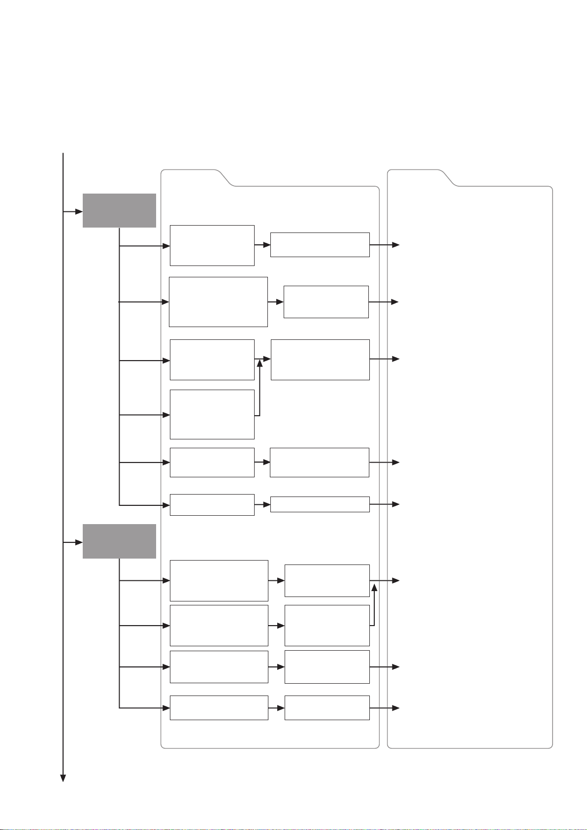
Replacement Options and
Module Selection Guide
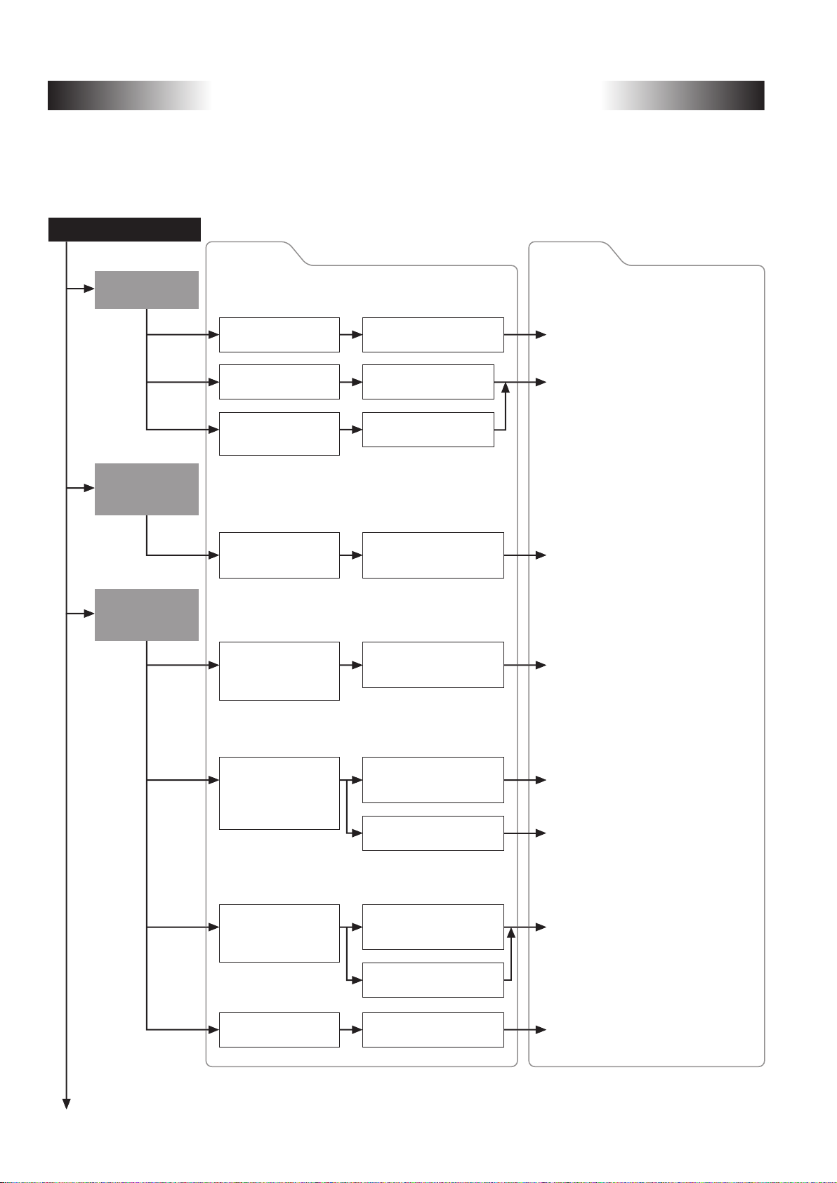
Specific modules are selected according to the transition procedure (gradually or simultaneously), module
configuration, and network configuration when replacing A/QnA (Large Type), AnS/QnAs (Small Type) Series
modules with Q/L Series modules.
The following shows module replacement options and references.
Module replacement
Replacing
A0J2HCPU
Modifying/Replacing
A (Large Type)
Series modules
Replacing
A (Large Type) Series
with Q Series
Options
To utilize existing
wiring
To replace with
Q Series I/O modules
To replace special
function modules with
Q Series modules
To add modules
to existing A (Large
Type) Series system
To only replace the CPU
module and continue using
existing A (Large Type)
Series modules
Use A0J2 renewal tool
manufactured by SC*
Select Q Series I/O
modules
Select Q Series modules
Modify/Replace modules
using A-A1S module
conversion adapter (A1ADP)
Replace modules using QA
extension base unit and
QA conversion adapter
1
References
Example: Section 2.4
Replace A0J2(H) systems with Q Series
using existing wiring
Transition from MELSEC-A0J2H Series
to Q Series Handbook
(L-08060ENG)
Example: Section 6.1
Use AnS (Small Type) modules as spare
parts for existing A (Large Type) Series
Example: Section 3.1.1
Utilize A/QnA (Large Type) Series QA6�B
extension base unit
Example: Section 3.1.2
Utilize existing I/O modules and extension
base unit with Q Series CPU
(Use QA conversion adapter)
To replace A (Large Type)
Series 32-point terminal
block type modules
without changing the
wiring configuration
To replace modules
when it is difficult to
use the Q Series
large type base unit
To replace all modules
with Q Series modules
*1: SC: Mitsubishi Electric System & Service Co., Ltd.
*2: MEE: Mitsubishi Electric Engineering Co., Ltd.
Artisan Technology Group - Quality Instrumentation ... Guaranteed | (888) 88-SOURCE | www.artisantg.com
Replace modules using
Q Series large type base unit
and I/O modules
Replace modules using upgrade
tool manufactured by MEE*
Replace modules using
terminal block converter
module and terminal module
Replace modules using FA
goods manufactured by MEE*
Select Q Series modules
2
2
18
Example: Section 2.1.2
Upgrade to Q Series using Q Series large
type base unit and I/O modules
Example: Section 2.1.3
Upgrade to Q Series using Q Series large
type base unit and I/O modules
Example: Section 2.1.2 (2)
Compatibility of Q Series large type
base unit with the upgrade tool
Example: Section 2.1.1
Install terminal block converter module
and terminal module externally
Transition from MELSEC-A/QnA
(Large Type) Series to Q Series
Handbook (Fundamentals)
(L-08043ENG)
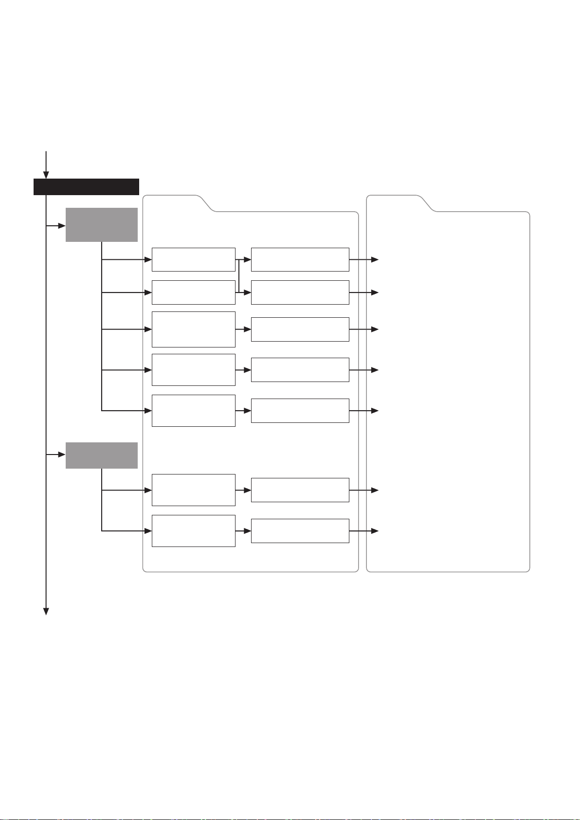
Page 22
Replacing AnS
(Small Type) Series
with Q Series
Options References
To only replace the CPU
module and continue
using the existing AnS
(Small Type) module
Replace modules using
QA1S extension base
Example: Section 3.2.1
Utilize AnS/QnAS (Small Type) Series
QA1S6�B extension base unit
Replacing AnS
(Small Type) Series
with L Series
To replace only the modules
in the main base unit and
continue using the existing
AnS (Small Type) modules
in the extension base unit
To mount Q Series base
unit using existing AnS
(Small Type) base unit
mounting holes
To replace existing AnS
(Small Type) 16-point
terminal block module
without changing the
wiring configuration
To replace modules when
it is difficult to use the Q
Series large type base unit
To replace all modules
with Q Series modules
To install L Series DIN rail
using existing AnS (Small
Type) base unit mounting
holes
Replace modules
using Q-Ans base unit
conversion adapter
Replace modules using
AnS (Small Type) Series
upgrade tool manufactured
by MEE*
Replace modules using FA
goods manufactured by
MEE*
Select Q Series modules
Use base adapter
integrated with DIN
rail
Example: Item 3.2.2
Replace main base unit with Q Series
and use existing extension base unit and
modules in it
(Use QA1S conversion adapter)
Example: Section 2.2.2
Utilize AnS/QnAS (Small Type) module
replacement upgrade tool
Example: Section 2.2.3
Replace AnS/QnAS (Small Type) Series
200 V AC input module A1SX20
[Use FA goods (manufactured by
Mitsubishi Electric Engineering Co., Ltd.)]
Transition from MELSEC-AnS/QnAS
(Small Type) Series to Q Series Handbook
(Fundamentals) (L(NA)08219ENG)
Example: Item 2.3.1
Replace using upgrade tool for replacing
with L Series
To replace existing AnS (Small
Type) 16-point terminal block
type modules without changing
the wiring configuration
To obtain information on
tools other than the
upgrade tool
To replace all modules
with L Series modules
*: MEE: Mitsubishi Electric Engineering Co., Ltd.
Artisan Technology Group - Quality Instrumentation ... Guaranteed | (888) 88-SOURCE | www.artisantg.com
Replace modules using
AnS (Small Type) Series
upgrade tool manufactured by MEE*
Replace modules using
FA goods manufactured
by MEE*
Select L Series
modules
19
Example: Item 2.3.2
Replace AnS/QnAS (Small Type) Series
200 V AC input module A1SX20
[Use FA goods (manufactured by
Mitsubishi Electric Engineering Co.,
Ltd.)]
Transition from MELSEC-AnS/QnAS
(Small Type) Series to L Series
Handbook (Fundamentals)
(L(NA)08258ENG)
Page 23
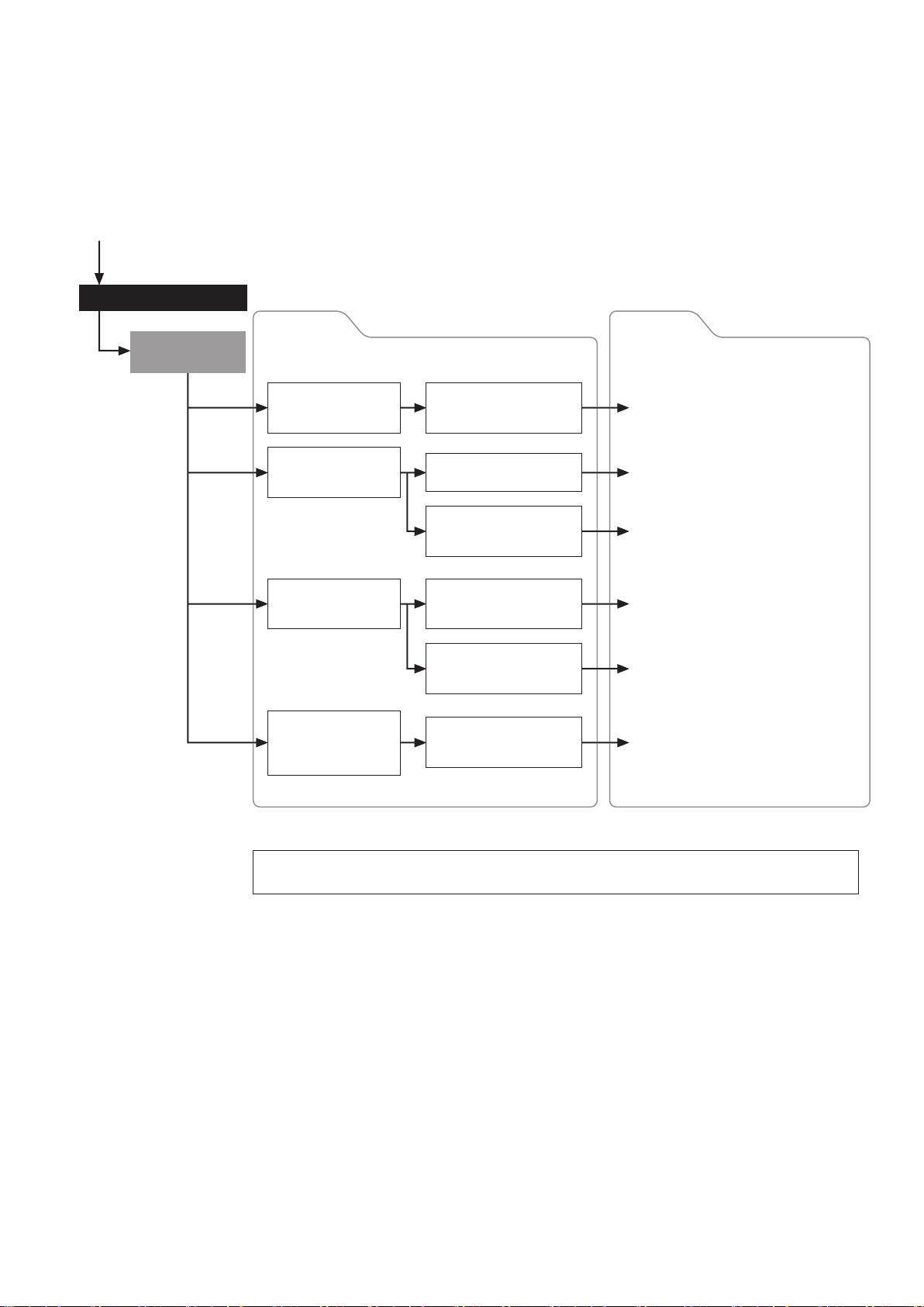
Network replacement
Replacing
MELSECNET/MINI
(S3) with CC-Link
Replacing
Replacing
MELSECNET(ΙΙ)
MELSEC-I/OLINK
Options References
To replace networks using
existing external wiring
To replace A2CCPU
To replace networks
when it is difficult to
use existing wiring
configuration
To replace
compact type remote
I/O modules
To replace building
block type remote
I/O modules
To replace networks
without changing
existing addresses
Replace network using A2C
shape I/O modules
Replace network using
wiring conversion adapter
Select CC-Link modules
Use A0J2 renewal tool
manufactured by SC*
Replace with MELSECNET/H
remote I/O network
Replace with CC-Link/LT
Example: Section 4.5.1
Replace A2CCPU with Q Series CPU
and CC-Link
Example: Section 4.5.2
Replace MELSECNET/MINI(-S3) with
CC-Link
Transition from MELSECNET/MINI-S3,
A2C(I/O) to CC-Link Handbook
(L-08061ENG)
Example: Section 2.4.3
Replace MELSECNET/MINI compact type
remote I/O modules with CC-Link
Example: Section 4.5.3
Replace MELSECNET/MINI(-S3) remote
I/O station with MELSECNET/H using the
existing external wiring
Example: Section 4.6
Replace MELSEC-I/OLINK with CC-Link/LT,
AnyWire DB A20
To replace networks
using existing
communication cables
*: SC: Mitsubishi Electric System & Service Co., Ltd.
Replace with AnyWire
DB A20
Example: Section 4.6
Replace MELSEC-I/OLINK with CC-Link/LT,
AnyWire DB A20
Artisan Technology Group - Quality Instrumentation ... Guaranteed | (888) 88-SOURCE | www.artisantg.com
20
Page 24
Network replacement
Replacing
MELSECNET(ΙΙ)
Options References
To replace CPU modules
while retaining the existing
MELSECNET(ΙΙ)
To replace with
MELSECNET/10 using
existing cables
To replace networks
containing a remote
I/O station
To gradually replace
networks using existing
MELSECNET(ΙΙ) and
MELSECNET/10
Replace modules using
MELSECNET(ΙΙ) local station
data link modules
Upgrade gradually to
Q Series CPU modules
Transition to MELSECNET/H
using MELSECNET/B twisted
pair cables
Replace networks using
MELSECNET/H PLC to PLC
network and remote I/O network
Change from remote I/O station
to normal station and replace
as one single network
Use a gateway set to
configure networks with
relay stations
Example: Section 4.2
Replace one of A Series stations with
Q Series while retaining MELSECNET(ΙΙ)
Example: Section 4.1.1
Replace MELSECNET(ΙΙ) coaxial loop
with MELSECNET/10 coaxial bus system
while retaining existing A Series CPUs
Example: Section 4.1.2
Upgrade to MELSECNET/H network
system utilizing existing MELSECNET/B
twisted pair cable
Transition from MELSEC-A/QnA
(Large Type) Series to Q Series
Handbook (Network Modules)
(L-08048ENG)
Example: Chapter 4.3
Replace MELSECNET containing a remote
I/O station with MELSECNET/H
Transition from MELSEC-A/QnA
(Large Type) Series to Q Series
Handbook (Network Modules)
(L-08048ENG)
This section describes the main replacement options. If multiple options are selected or other options
are needed, comprehensive consideration is required to configure the system.
Artisan Technology Group - Quality Instrumentation ... Guaranteed | (888) 88-SOURCE | www.artisantg.com
21
Page 25

MEMO
Artisan Technology Group - Quality Instrumentation ... Guaranteed | (888) 88-SOURCE | www.artisantg.com
22
Page 26

PartⅠ: Hardware
Artisan Technology Group - Quality Instrumentation ... Guaranteed | (888) 88-SOURCE | www.artisantg.com
23
Page 27
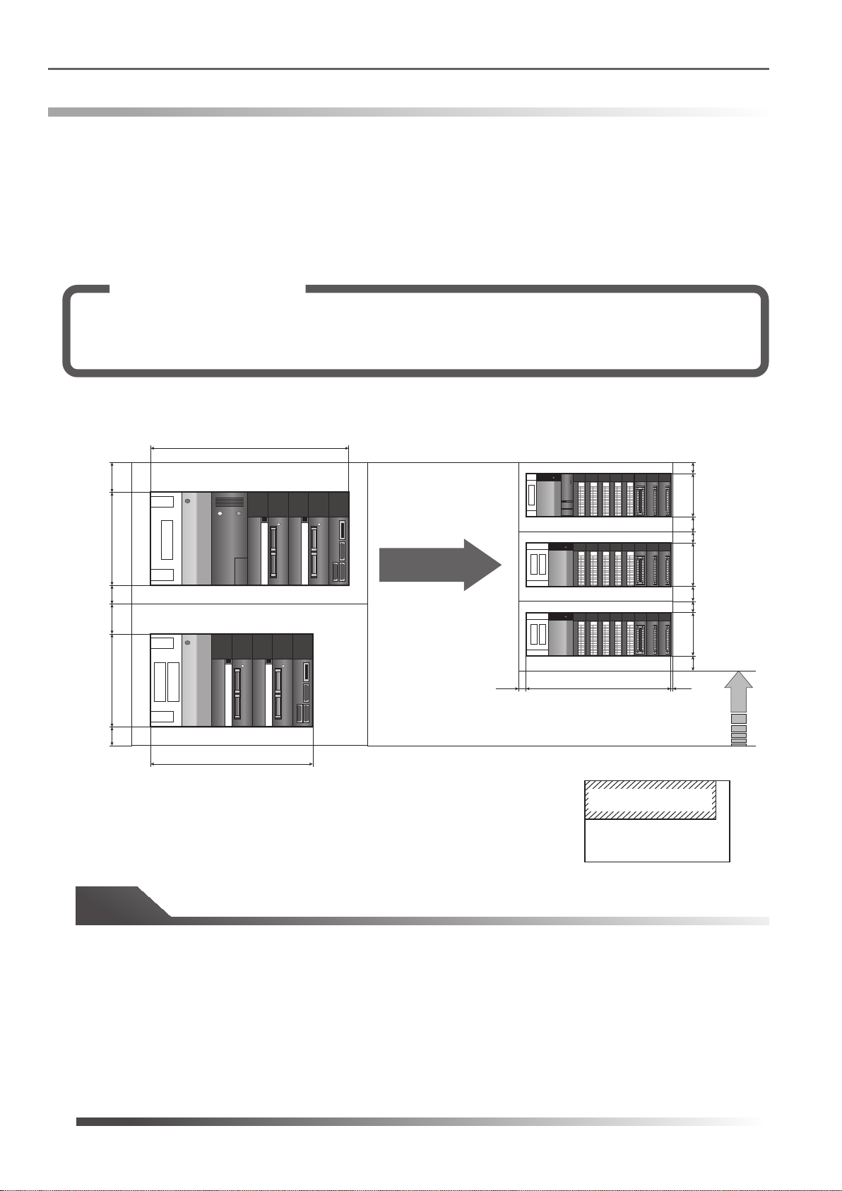
1.1 Comparison of A/QnA (Large Type) Series and Q Series base unit mounting area
Comparison of base mounting area
1.
1.1 Comparison of A/QnA (Large Type) Series and Q Series base unit mounting area
When upgrading existing A/QnA systems, there are cases where the number of modules increases due to
specification differences. For instance, to replace an A/QnA (Large Type) Series 32-point terminal block type I/O
module, two Q Series 16-point terminal block type I/O modules are used. Despite increase in the number of I/O
slots and extension base stages, the Q Series footprint is smaller than that of the A/QnA (Large Type) Series.
The following example shows a comparison of the mounting areas when the A/QnA (Large Type) Series system
is upgraded to the Q Series.
Solution and Benefit
When replacing each 32-point terminal block type module with two 16-point terminal block type
modules, an additional extension base unit is required due to an increase in the number of modules.
However, the Q Series system fits inside the existing control panel because it is compact in size.
(1) When the A/QnA (Large Type) Series main base unit A35B and the A65B extension base unit are
replaced
250
250
382
80
A35B
Q38B/Q68B
0
0
0
0
1
1
1
1
2
2
2
2
3
3
3
3
4
4
4
4
5
5
5
5
6
6
6
6
7
7
7
7
8
8
8
8
9
9
9
9
A
A
A
A
B
B
B
B
C
C
C
C
D
D
D
D
E
E
E
E
F
F
F
F
30
0
1
2
3
4
5
6
7
8
9
A
B
C
D
E
F
98
40
30
0
0
0
0
1
2
3
4
5
6
7
Replace
8
9
A
B
C
D
E
F
50
0
1
1
1
1
2
2
2
2
3
3
3
3
4
4
4
4
5
5
5
5
6
6
6
6
7
7
7
7
8
8
8
8
9
9
9
9
A
A
A
A
B
B
B
B
C
C
C
C
D
D
D
D
E
E
E
E
F
F
F
F
98
40
30
80
A65B
0
0
0
0
1
2
3
4
5
6
7
8
9
A
B
C
D
E
F
0
1
1
1
1
2
2
2
2
3
3
3
3
4
4
4
4
5
5
5
5
6
6
6
6
7
7
7
7
8
8
8
8
9
9
9
9
A
A
A
A
B
B
B
B
C
C
C
C
D
D
D
D
E
E
E
E
F
F
F
F
98
40
20 5
50
352
328
Downsized
Unit: mm
Q38B/Q68B
A35B
Base unit size comparsion
Tip
The A/QnA (Large Type) Series main base unit and extension base unit differ in size:
• A35B main base unit: 382 mm (W) x 250 mm (H)
• A65B extension base unit: 352 mm (W) x 250 mm (H)
Whereas the Q Series main base unit and extension base unit are the same size:
• Q38B main base unit/Q68B extension base unit: 328 mm (W) x 98 mm (H)
Even with the extra I/O slots and base units, the base unit installation area for Q Series is smaller than that for
A/QnA (Large Type) Series.
Artisan Technology Group - Quality Instrumentation ... Guaranteed | (888) 88-SOURCE | www.artisantg.com
24
Page 28
1.1 Comparison of A/QnA (Large Type) Series and Q Series base unit mounting area
(2) When the A/QnA (Large Type) Series main base unit A38B and the A68B extension base unit are
replaced
250
250
480
80
A38B
Q312B/Q612B
0
0
0
0
0
0
1
1
1
2
2
2
3
3
3
4
4
4
5
5
5
6
6
6
7
7
7
8
8
8
9
9
9
A
A
A
B
B
B
C
C
C
D
D
D
E
E
E
F
F
F
0
1
1
1
1
2
2
2
2
3
3
3
3
4
4
4
4
5
5
5
5
6
6
6
6
7
7
7
7
8
8
8
8
9
9
9
9
A
A
A
A
B
B
B
B
C
C
C
C
D
D
D
D
E
E
E
E
F
F
F
F
30
0
0
1
1
2
2
3
3
4
4
5
5
6
6
7
7
8
8
9
9
A
A
B
B
C
C
D
D
E
E
F
F
98
40
30
0
0
0
0
0
0
0
0
1
1
1
1
1
2
2
2
2
2
3
3
3
3
3
4
4
4
4
4
5
5
5
5
5
6
6
6
6
6
7
7
7
7
7
8
8
8
8
8
9
9
9
9
9
A
A
A
A
Replace
B
C
D
E
F
A
B
B
B
B
C
C
C
C
D
D
D
D
E
E
E
E
F
F
F
F
50
0
1
1
1
1
2
2
2
2
3
3
3
3
4
4
4
4
5
5
5
5
6
6
6
6
7
7
7
7
8
8
8
8
9
9
9
9
A
A
A
A
B
B
B
B
C
C
C
C
D
D
D
D
E
E
E
E
F
F
F
F
98
40
30
80
A68B
0
0
0
0
0
0
0
0
1
1
1
1
1
2
2
2
2
2
3
3
3
3
3
4
4
4
4
4
5
5
5
5
5
6
6
6
6
6
7
7
7
7
7
8
8
8
8
8
9
9
9
9
9
A
A
A
A
A
B
B
B
B
B
C
C
C
C
C
D
D
D
D
D
E
E
E
E
E
F
F
F
F
F
0
1
1
1
1
2
2
2
2
3
3
3
3
4
4
4
4
5
5
5
5
6
6
6
6
7
7
7
7
8
8
8
8
9
9
9
9
A
A
A
A
B
B
B
B
C
C
C
C
D
D
D
D
E
E
E
E
F
F
F
F
98
40
20
50
466
439 5
Downsized
Unit: mm
Q312B/Q612B
A38B
Base unit size comparsion
Tip
The A/QnA (Large Type) Series main base unit and extension base unit differ in size:
• A38B main base unit: 480 mm (W) x 250 mm (H)
• A68B extension base unit: 466 mm (W) x 250 mm (H)
Whereas the Q Series main base unit and extension base unit are the same size:
• Q312B main base unit/Q612B extension base unit: 439 mm (W) x 98 mm (H)
Even with the extra I/O slots and base units, the base unit installation area for Q Series is smaller than that for
A/QnA (Large Type) Series.
Artisan Technology Group - Quality Instrumentation ... Guaranteed | (888) 88-SOURCE | www.artisantg.com
25
Page 29
1.2 Comparison of AnS/QnAS (Small Type) Series and Q Series base unit mounting area
1.2 Comparison of AnS/QnAS (Small Type) Series and Q Series base unit mounting area
The Q Series is compact, and has a smaller mounting area.
It can be mounted within the AnS/QnAS (Small Type) mounting area.
The following example shows a comparison of the mounting areas when the AnS/QnAS (Small Type) Series
system is upgraded to the Q Series.
Solution and Benefit
Using the “AnS to Q Series conversion adapter” (manufactured by Mitsubishi Electric Engineering
Co., Ltd.), the 16-point terminal block type module can fit into the existing space without changing
the wiring.
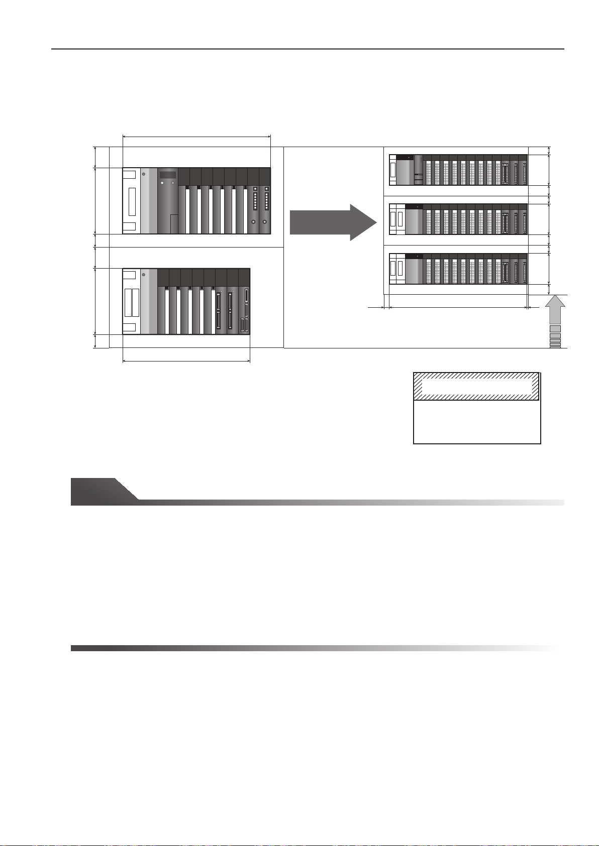
(1) When the AnS/QnAS (Small Type) Series main base unit A1S35B and the A1S65B extension base
unit are replaced
30
130
30
30
130
30
325
A1S35B
A1S65B
315
Q35B/Q65B Q38B/Q68B
Q38B
/Q68B
Replace
328
Q38B/Q68B
0
0
0
0
1
1
2
2
3
3
4
4
5
5
6
6
7
7
8
8
9
9
A
A
B
B
C
C
D
D
E
E
F
F
0
1
1
1
2
2
2
3
3
3
4
4
4
5
5
5
6
6
6
7
7
7
8
8
8
9
9
9
A
A
A
B
B
B
C
C
C
D
D
D
E
E
E
F
F
F
Q35B/Q65B
0
0
0
0
1
1
2
2
3
3
4
4
5
5
6
6
7
7
8
8
9
9
A
A
B
B
C
C
D
D
E
E
F
F
0
1
1
1
2
2
2
3
3
3
4
4
4
5
5
5
6
6
6
7
7
7
8
8
8
9
9
9
A
A
A
B
B
B
C
C
C
D
D
D
E
E
E
F
F
F
24520 5
Q312B
/Q612B
30
98
40
30
98
40
Unit: mm
A1S38BA1S35B
Base unit size comparsion
Artisan Technology Group - Quality Instrumentation ... Guaranteed | (888) 88-SOURCE | www.artisantg.com
26
Page 30
1.2 Comparison of AnS/QnAS (Small Type) Series and Q Series base unit mounting area
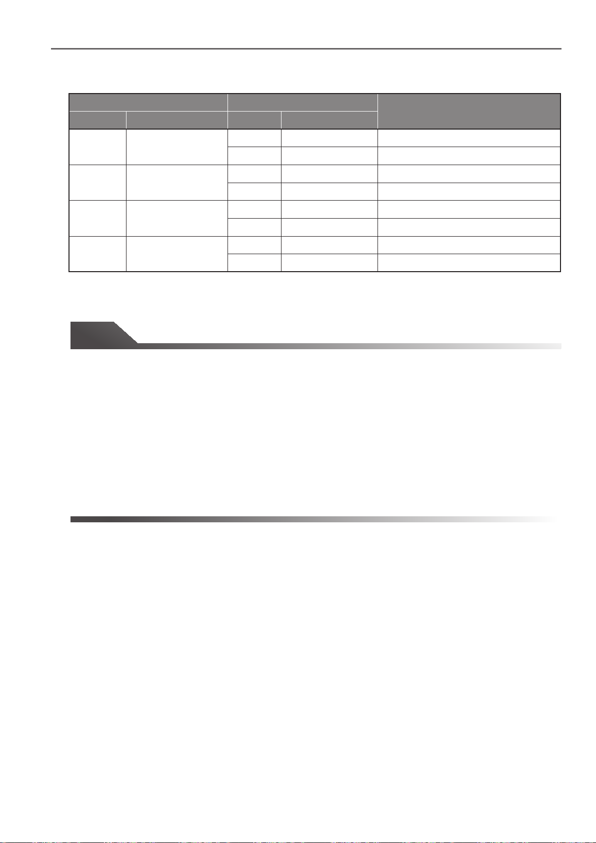
Existing base unit Replacement base unit
Model Outline dimensions Outline dimensionsModel
A1S35B
A1S38B
A1S65B
A1S68B
325(W)×130(H)
430(W)×130(H)
315(W)×130(H)
420(W)×130(H)
Q35B
Q38B
Q38B
Q312B
Q65B
Q68B
Q68B
Q612B
245(W)×98(H)
328(W)×98(H)
328(W)×98(H)
439(W)×98(H)
245(W)×98(H)
328(W)×98(H)
328(W)×98(H)
439(W)×98(H)
Width is 80 mm narrower
Width is 3 mm wider
Width is 102 mm narrower
Width is 9 mm wider
Width is 70 mm narrower
Width is 13 mm wider
Width is 92 mm narrower
Width is 19 mm wider
Tip
The AnS /QnA (Small Type) Series main base unit and extension base unit differ in size:
• A1S35B main base unit: 325 mm (W) x 130 mm (H)
• A1S65B extension base unit: 315 mm (W) x 130 mm (H)
Remarks
Whereas the Q Series main base unit and extension base unit are the same size:
• Q38B main base unit/Q68B extension base unit: 328 mm (W) x 98 mm (H)
The width will increase if the number of modules increases, i.e., A1S35B to Q68B will increase 3 mm, and
A1S38B to Q312B will increase by 9 mm.
However, this increase can be handled. Confirm the in-panel layout and space and determine whether the
extra modules can be mounted.
Artisan Technology Group - Quality Instrumentation ... Guaranteed | (888) 88-SOURCE | www.artisantg.com
27
Page 31

299
325
1.3 Comparison of AnS/QnAS (Small Type) Series and L Series mounting area
1.3 Comparison of AnS/QnAS (Small Type) Series and L Series mounting area
The L Series modules are designed to be installed directly on the DIN rails. The modules can be
mounted freely according to the in-panel space.
When replacing AnS/QnAS (Small Type) Series modules with L Series, examine the mounting method
in consideration of the in-panel space.
Solution and Benefit
(1) Using the "AnS to L Series conversion adapter" (manufactured by Mitsubishi Electric
Engineering Co., Ltd.), the module to be mounted has a wiring connector incompatible with
the terminal block of the terminal block type module can fit into the existing space without
changing the wiring.
(2) The number of modules to be newly mounted can be reduced by using various built-in
functions of the CPU.
unit are replaced
30
130
30
30
130
30
A1S35B
A1S65B
■ Built-in functions of CPU
315
General-purpose input function Interrupt input function Pulse catch function
General-purpose output function
Replace
30
90
30
90
30
229
Unit: mm
Positioning function
Ethernet function
CC-Link function
High-speed counter function
*1
*1: The CC-Link function can
be used on L26CPU-BT and
L26CPU-PBT.
Tip
Although the external dimensions of AnS/QnAS (Small Type) Series are determined by the base unit to be
used, the width of L Series varies depending on the number of selected modules.
For the method for calculating the required width, refer to "Transition from MELSEC-AnS/QnAS (Small Type)
Series to L Series Handbook."
Artisan Technology Group - Quality Instrumentation ... Guaranteed | (888) 88-SOURCE | www.artisantg.com
28
Page 32

2.1 Replace A/QnA (Large Type) Series with Q Series
Utilizing external wiring
2.
2.1 Replace A/QnA (Large Type) Series with Q Series
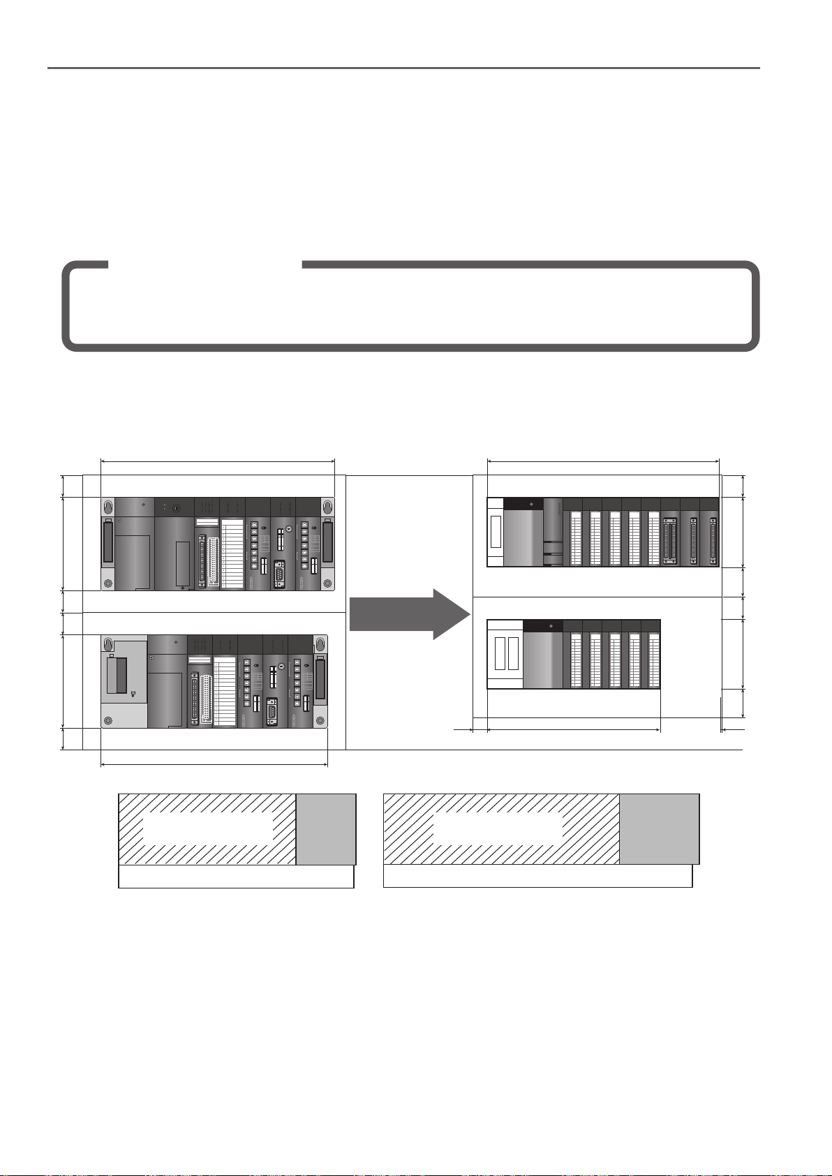
2.1.1 Install terminal block converter module and terminal module externally
(1) Replace 32-point terminal block type module using connector/terminal block converter module
Solution and Benefit
• The connector/terminal block converter module can support up to 2mm2 wires, allowing the use
of existing thick wires without modification.
• Using a connector/terminal block converter module, an existing 32-point terminal block type
module can be replaced with a 32-point connector type module without increasing the number of
modules.
The following is an example of replacing an A/QnA (Large Type) Series system that contains 32-point terminal
block type input modules (AX41).
● Instructions
Replace AX41 with QX41, and connect the connector/terminal block converter module.
If QX40 is used instead of QX41, two modules are required to replace each AX41. Also, if existing wires are
thicker than the applicable wire size (0.75 mm2), wiring modifications may be necessary.
(a) System configuration example
Current configuration After replacement
1
*
QY10
QX41
(16)
1
*
QY10
QX41
W=328 mm
QX41
1
*
1
*
W=328 mm
(16)
(16)
QY10
QY10
QX41
(16)
QX42
(16)
QY10
(16)
QY10
(16)
QY10
(16)
QY10
(16)
QY10
(16)
QY10
Empty
W=382 mm
A61P
A35B
A61P
A65B
AX41
A2NCPU
X00... X20... X40... X60... X80...
W=352 mm
AY13
AY13
YC0... YE0... Y100... Y120...Y140...
AX41
AY13
AX41
AY13
AX41
AY13
H=250 mm
AX42
H=250 mm
Replace
Q01UCPU
Q61P
Q38B
Q61P
Q68B
*1: Connector/terminal block converter module (A6TBXY36)
(b) Module selection example
Product name
Power supply module A61P Q61P2
CPU module A2NCPU Q01UCPU1 1
Main base unit A35B Q38B1 1
Extension base unit A65B Q68B1 1
Extension cable AC06B QC06B1 1
Input module AX41 QX414 4
Connector/terminal block converter module N/A A6TBXY36- 4
Connector/terminal block converter module cable N/A AC�TB- 4
Input module AX42 QX421 1
Output module AY13 QY105 10
Existing model Replacemant model
H=98 mm
H=98 mm
2
Artisan Technology Group - Quality Instrumentation ... Guaranteed | (888) 88-SOURCE | www.artisantg.com
29
Page 33

2.1 Replace A/QnA (Large Type) Series with Q Series
Connector/terminal block converter module
Width
(All models have the same height and depth)
H=78.5 mm
W=120 mm
D=52 mm
A6TBXY36
A6TBXY54
A6TBX70
120 mm
155 mm
190 mm
A6TBXY36 (for 32 points)
Specifications
Model Outline Weight Applicable crimping terminal
A6TBXY36
A6TBXY54
A6TBX70
A6TBX36-E
A6TBX54-E
A6TBX70-E
A6TBY36-E
A6TBY54-E
For positive common input modules and sink output modules (standard type)
For positive common input modules and sink output modules (2-wire type)
For positive common input modules (3-wire type)
For negative common input modules (standard type)
For negative common input modules (2-wire type)
For negative common input modules (3-wire type)
For source output modules (standard type)
For source output modules (2-wire type)
0.4 kg
0.5 kg
0.6 kg
0.4 kg
0.5 kg
0.6 kg
0.4 kg
0.5 kg
Applicable
wire size
0.75 to
2 mm
1.25-3.5 (JIS)
1.25-YS3A (J.S.T.)
V1.25-M3 (J.S.T.)
V1.25-YS3A (J.S.T.)
2
2-3.5 (JIS)
2-YS3A (J.S.T.)
V2-S3 (J.S.T.)
V2-YS3A (J.S.T.)
Cables
Model Outline Weight Applicable model
AC05TB 0.5 m, for sink type modules A6TBXY36
AC10TB 1 m, for sink type modules 0.23 kg
AC20TB 2 m, for sink type modules 0.37 kg
AC30TB 3 m, for sink type modules 0.51 kg
AC50TB 5 m, for sink type modules 0.76 kg
AC80TB 8 m, for sink type modules (common current: 0.5 A or lower) 1.2 kg
AC100TB 10 m, for sink type modules (common current: 0.5 A or lower) 1.5 kg
AC05TB-E 0.5 m, for source type modules 0.17 kg
AC10TB-E 1 m, for source type modules 0.23 kg
AC20TB-E 2 m, for source type modules 0.37 kg
AC30TB-E 3 m, for source type modules 0.51 kg
AC50TB-E 5 m, for source type modules 0.76 kg
0.17 kg
A6TBXY54
A6TBX70
A6TBX36-E
A6TBY36-E
A6TBX54-E
A6TBY54-E
A6TBX70-E
Artisan Technology Group - Quality Instrumentation ... Guaranteed | (888) 88-SOURCE | www.artisantg.com
30
Page 34

2.1 Replace A/QnA (Large Type) Series with Q Series
(2) Replace 32-point contact output type module using "relay terminal module"
Solution and Benefit
• Using the relay terminal modules, a large type A (Large Type) Series 32-point contact output
module can be replaced while maintaining 8 points/common.
• A wide variety of compatible wire sizes are available using the relay terminal module.
A (Large Type) Series 32-point contact output module AY13: Max. 2 mm
Relay terminal module: Max. 1.25 mm
Q Series 16-point contact output module QY10: Max. 0.75 mm
2
2
• Replacement is possible without the need of additional modules because a module mounted on
the base unit becomes compatible with 32-point connector type modules through the use of the
"connector/terminal block converter module".
The following is an example of replacing contact output modules (AY13) with transistor output modules (QY41P)
and externally converting transistor outputs into contact outputs.
● Instructions
Replace AY13 with QY41P and connect the relay terminal modules to convert to contact outputs.
With this method, the system can be upgraded without increasing the number of modules on the base unit.
Also, 8 points/common, the same specification as that of the AY13, can be maintained.
2
(a) System configuration example
Current configuration After replacement
A61P
A35B
A61P
A65B
AX41
A2NCPU
X00... X20... X40... X60... X80...
AY13
AY13
YC0... YE0... Y100... Y120...Y140...
AX41
AY13
AX41
AY13
AX41
AY13
AX42
Replace
Q61P
Q61P
QX41
Q01UCPU
QY41P
QX41
QY41P
QY41P
8 points/common
(the same specification
as that of AY13)
QX41
QY41P
QX41
QY41P
QX42
QY41P
Dedicated cable
(AC�TE)
Reray terminal module Reray terminal module
16-point relay terminal module x 2
(A6TE2-16SRN)
Artisan Technology Group - Quality Instrumentation ... Guaranteed | (888) 88-SOURCE | www.artisantg.com
31
Page 35

2.1 Replace A/QnA (Large Type) Series with Q Series
(b) Module selection example
Product name
Existing model Replacement model
Power supply module A61P Q61P2
CPU module A2NCPU Q01UCPU1 1
Main base unit A35B Q38B*1 1
Extension base unit A65B Q68B1 1
Extension cable AC06B QC06B1 1
Input module AX41 QX41-S24 4
Connector/terminal block converter module N/A A6TBXY36- 4
Cable (for connector/terminal block converter module)
N/A AC�TB- 4
Input module AX42 QX421 1
Output module AY13 QY41P5 5
Relay terminal module N/A A6TE2-16SRN- 10
Cable (for relay terminal module) N/A AC06TE- 5
* The Q312 can be used if the control panel is wide enough. With the Q312, the I/O modules can be mounted on one base unit,
eliminating the need for the Q68B extension base unit, QC06B extension cable, and one Q61P power supply module.
(c) Relay terminal module (A6TE2-16SRN)
(d) External dimensions
Unit: mm
2
Note: The relay terminal module can function as a relay
terminal block while performing contact outputs.
(e) Cables
The connection cables compatible with A6TE2-16SRN are shown below.
Model Length (L)
AC06TE 0.6 m
AC10TE 1 m
AC30TE 3 m
AC50TE 5 m
AC100TE 10 m
Artisan Technology Group - Quality Instrumentation ... Guaranteed | (888) 88-SOURCE | www.artisantg.com
32
52.6
B-side: Second half
16 pts. (Y10 to Y1F)
L
350 mm
B
A
350 mm
A-side: First half
16 pts. (Y0 to YF)
Page 36

2.1 Replace A/QnA (Large Type) Series with Q Series
(f) Specifications comparison between AY13 and A6TE2-16SRN
Item AY13
Number of output points
32 points
Isolation method
Rated switching
voltage/current
24 V DC/2 A (resistive load)/point,
240 V AC/2 A (cos Ф =1)/point,
5 A/common
Minimum switching load 5 V DC 1 mA ○5 V DC 1 mA
Maximum switching
voltage
Response
time
ON to OFF
OFF to ON 12 ms or less ○12 ms or less
264 V AC
125 V DC
Mechanical
Rated switching voltage/current
load: 200,000 times or more
Life
Electrical
Maximum switching
frequency
Common terminal
arrangement
200 V AC 1.5 A, 240 V AC 1 A
(cos Ф =0.7): 200,000 times or more
200 V AC 0.7 A, 240 V AC 0.5 A
(cos Ф =0.35): 200,000 times or more
24 V DC 1 A, 100 V DC 0.1 A
(L/R=7 ms): 200,000 times or more
3600 times/hour
8 points/common
(common terminals:
TB9, TB18, TB27, TB36)
A6TE2-16SRN
16 points △
Relay △Photocoupler
24 V DC/2 A (resistive load)/point,
240 V AC/2 A (cos Ф =1)/point,
8 A/common
264 V AC
125 V DC
10 ms or less ○10 ms or less
20 million times or more ○20 million times or more
Rated switching voltage/current
load: 100,000 times or more
200 V AC 1.5 A, 240 V AC 1 A
(cos Ф =0.7): 100,000 times or more
200 V AC 0.7 A, 240 V AC 0.5 A
(cos Ф =0.35): 100,000 times or more
24 V DC 1 A, 100 V DC 0.1 A
(L/R=7 ms): 100,000 times or more
3600 times/hour
8 points/common
(common terminals:
TB19, TB21)
Compati-
bility
○
○
△
△
○
○
○: Compatible, △: Partially changed
Remarks
Use two A6TE2-16SRN modules
when using more than 16 points.
The isolation method differs, but the
isolation performance is equivalent.
The electrical life of
the A6TE2-16SRN is half of
the AY13's life. However, the relay
for the A6TE2-16SRN can be
replaced.
Operation indicator ON indication (LED) ○ON indication (LED)
External
Voltage
power
supply
Current
External connections
Applicable wire size
Applicable crimping
terminal
24 V DC ±10%
Ripple voltage: 4 Vp-p or less
290 mA
(TYP. 24 V DC, all points ON)
38-point terminal block
connector (M3 × 6 screws)
0.75 to 2 mm2
R1.25-3, R2-3,
RAV1.25-3, RAV2-3
24 V DC ±10%
Ripple voltage: 4 Vp-p or less
350 mA
(TYP. 24 V DC, all points ON)
38-point screw terminal block
(M3 screw) (M3 × 6 screws)
0.75 to 1.25 mm
2
R1.25-3, R1.25-MS3,
R1.25-B3A, R1.25-C3A,
RAV1.25-3, RAV1.25-MS3,
RAV1.25-B3A
○
The supplied current value will be
larger.
△
△
△
Wiring modification is required.
○
Artisan Technology Group - Quality Instrumentation ... Guaranteed | (888) 88-SOURCE | www.artisantg.com
33
Page 37

2.1 Replace A/QnA (Large Type) Series with Q Series
(3) Replace A/QnA (Large Type) Series 200 V AC input module AX21
[Use FA goods (manufactured by Mitsubishi Electric Engineering Co., Ltd.)]
Solution and Benefit
• Use the Q Series large type input module QX21L to replace the modules without changing the
wiring.
Note that if the Q Series large type base unit cannot be used because of space limitations in the
panel or because of the module configuration, etc., replacements can be completed easily by
using the FA goods.
• A dedicated cable is available to connect the programmable controller with the FA goods, so
there's no need to prepare cables when making a replacement.
FA goods
A variety of FA goods, including a terminal block connector conversion module, I/O type converter (AC input ->
DC input conversion, DC output signal -> relay output conversion, etc.), are available. Use these convenient
products as relays, signal conversions and a means to reduce wiring when compatible modules are not available
for replacing from the A/QnA (Large Type) Series to the Q Series.
The following is an example of replacing the A (Large Type) I/O module with the Q Series using FA goods.
● Instruction
(1) Using the FA goods, convert the 200 V AC input into 24 V DC, and lead it in with QX41, etc.
(2)
The external wiring will change, but program does not need to be changed since the I/O address is the same
(3) The following FA goods are used.
Product name Model
External connection
Remarks
(1) 200 V AC input module insulated with
photo coupler
(2)
Input module on programmable controller side
QX41, QX42, QH42 and QX41Y41P
(3) CC-Link module
AJ65SBTCF1-32D
200 V AC photo
coupler insulated
input module
FA-TH16X200A31L
16-point/common
2-wire type
(4) Connection cable
FA-CBL���FM2V and FA-CBL���FM2LV
● System configuration example
Current configuration New configuration after replacement
QX41
(1)
QX41
(2)
I/O
module
FA-TH16X200A31L
FA-TH16X200A31L
I/O
module
I/O
module
A61P
A35B
AX21
AX21
(1)
32points
X000~
(2)
32points
X020~
A2N
CPU
(200 V AC 32-point input for AX21)
I/O
module
I/O
module
I/O
module
Replace
Q01U
Q61P
CPU
Q35B
FA-TH16X200A31L
FA-TH16X200A31L
.
● Application (CC-Link input module)
AJ65SBTCF1-32D
CC-Link
other stations
FA-CBL06FM2LV
Artisan Technology Group - Quality Instrumentation ... Guaranteed | (888) 88-SOURCE | www.artisantg.com
200 V AC input
FA-TH16X200A31L
200 V AC input
FA-TH16X200A31L
34
Page 38

● Connection cable
2.1 Replace A/QnA (Large Type) Series with Q Series
Shape Model Cable length
● Module external dimensions
10 10
4.75
FA-TH16X100A31
AC100V Input module
FA-CBL06FM2LV
FA-CBL10FM2LV
FA-CBL20FM2LV
FA-CBL30FM2LV
FA-CBL50FM2LV
FA-CBL100FM2LV
175
155
0.6m
1.0m
2.0m
3.0m
5.0m
10.0m
2-φ8
2-φ4.5
EDCBA9876543210
26.9
27.535.58.5
71.5
120°
Simple lock
53.4
Unit: mm
7.26 59.5
7.62
12
5
DIN rail
● Module selection example
Product name
Power supply module
CPU module
Main base unit
Input module
A61P
A2NCPU
A35B
AX21
FA goods : Input module N/A −
Connection cable
N/A
Existing model Replacement model
1
Q61P
1
Q01UCPU
1
Q35B
2
QX41 or QX42
FA-TH16X200A31L
FA-CBL□□FM2V
−
FA-CBL□□□FM2LV
2/1
Tip
• The FA goods input module has a function to convert 200 V AC input signal into 24 V DC, so select a 24 V
DC input connector type module for the programmable controller side input module.
• The following products are available for the FA goods.
Triac large capacity (1 A/point) output module
Transistor large capacity (2 A/point) output module
Common multi-point I/O module
The FA goods can be used when replacement using the Q Series large type I/O module conversion adapter
is difficult.
For details on the FA goods manufactured by Mitsubishi Electric Engineering Co., Ltd., please contact your
local Mitsubishi sales office or representative.
• To replace using existing external wiring terminal block, use the Q Series large type input module QX21L.
Refer to "2.2 Upgrade to Q Series using Q Series large type base unit and I/O modules" for details.
1
1
1
4
2
Artisan Technology Group - Quality Instrumentation ... Guaranteed | (888) 88-SOURCE | www.artisantg.com
35
Page 39

2.1 Replace A/QnA (Large Type) Series with Q Series
2.1.2 Replace using Q Series large type base unit and Q Series large input/output module
(1) List of Q Series large type base units and Q Series large input/output modules
Solution and Benefit
• The Q Series large type I/O modules allow the use of existing A/QnA (Large Type) Series 32-point
I/O wiring, eliminating the need for rewiring.
• Performance specifications of the Q Series large type I/O modules are equivalent to those of the
A/QnA (Large Type) Series.
• The hole size and pitch of the Q Series large type base units are the same as those of the A/QnA
(Large Type) Series, eliminating the need of making new mounting holes.
• The Q Series large type I/O modules and standard Q Series modules can be mounted together on
the Q Series large type base unit. For the standard Q Series modules, existing A/QnA (Large
Type) Series connectors or terminal blocks can be utilized without modification by using a
conversion adapter (upgrade tool) manufactured by Mitsubishi Electric Engineering Co., Ltd.
Wired terminal blocks of the existing A (Large Type) Series I/O modules can be mounted directly without
modifying the external wiring.
Mount a standard Q Series
power supply module and
CPU module
Q Series large type
I/O module
Q Series large type
base unit
Q Series module
Q Series module
Q Series large type
I/O module
Mount directly
Remove the wired
terminal block
from the existing
I/O module
Upgrade tool (Conversion adapter)
manufactured by Mitsubishi Electric
Engineering Co., Ltd.
Mount directly
Remove the wired
terminal block
from the existing
I/O module
● Q Series large type base unit options
Product name
Main base unit
Extension base
unit
Model Outline
Q38BL
Q35BL
Q68BL
8 slots, 1 power supply module required, Q Series large type I/O module mountable
5 slots, 1 power supply module required, Q Series large type I/O module mountable
8 slots, 1 power supply module required, Q Series large type I/O module mountable
Q65BL 5 slots, 1 power supply module required, Q Series large type I/O module mountable
Q55BL
Artisan Technology Group - Quality Instrumentation ... Guaranteed | (888) 88-SOURCE | www.artisantg.com
5 slots, power supply module not required, Q Series large type I/O module mountable
Q Series large type blank cover (QG69L)
(To mount a standard Q Series module
on a large type base unit)
36
Page 40

● Q Series large type I/O module options
2.1 Replace A/QnA (Large Type) Series with Q Series
Product name
Input module
Output module
Large type
blank cover
Existing A (Large Type)
AX11
AX21
AY10A
AY11A
AY13
AY23
AY41(P)
AY51
AY51-S1
N/A
Model
Series module
Q Series
module
QX11L
QX21L
QY11AL
QY13L
QY23L
QY51PL
QG69L
32 points, 100 to 120 V AC, rated input current:10 mA (100 V AC, 60 Hz),
response time: 15 ms or less (OFF to ON), 25 ms or less (ON to OFF),
32 points/common, 38-point terminal block
32 points, 200 to 240 V AC, rated input current: 10 mA (220 V AC 60 Hz),
response time: 15 ms or less (OFF to ON), 25 ms or less (ON to OFF),
32 points/common, 38-point terminal block
16-point contact output, 24 V DC/240 V AC, 2 A/point, 16 A/all points,
All points independent common, 38-point terminal block,
Surge suppressor (Varistor 387 to 473 V)
32-point contact output, 24 V DC/240 V AC, 2 A/point, 5 A/common,
8 points/common, 38-point terminal block
32-point triac output, 100 to 240 V AC, 0.6 A/point, 2.4 A/common,
8 points/common, 38-point terminal block
32-point transistor output 12 to 24 V DC, 0.5 A/point, 4 A/common,
16-point/common protection function (overheat protection function,
overload protection function), 38-point terminal block
Blank cover for mounting existing Q Series module on the Q Series large
type base unit
Outline
● Conversion adapter (upgrade tool) options
[manufactured by Mitsubishi Electric Engineering Co., Ltd.]
Product name
Output module
Analog input
module
Analog output
module
High-speed counter
module
* Voltage input or current input is applicable to replacement Q Series modules.
If the existing A (Large Type) Series module uses a combination of voltage and current input, it cannot be replaced using a Q Series
large type base unit and a conversion adapter.
Consider using a conversion adapter (2-slot type) to replace the module with a Q64AD-GH (2 units required). (Refer to Section 2.4 for details)
Existing A (Large Type) Series module
AX10
AX40, AX40-UL
AX70, AX70-UL
AX50, AX50-S1
AX80, AX80-UL QX80Input module
AX41, AX41-UL QX41, QX41-S2, QX71
AX31-S1
AX41-S1 QX41-S1
AX71 QX71
AX81, AX81-S1
AY10
AY11, AY11-UL
AY11E
AY11EEU
AY22
AY40, AY40P,AY40-UL
AY70, AY70-UL
AY50, AY50-UL
AY80
AY41, AY41P, AY41-UL
AY71 QY71
AY81, AY81EP
A68AD*
A68AD-S2*
A68ADN*
A62DA, A62DA-S1
A68DAV
A68DAI, A68DAI-S1
AD61
AD61-S1
QX10
QX40, QX70
QX40-S1
QX70
QX50
QX41, QX41-S2
QX81, QX81-S2
QY10
QY22
QY40P
QY70
QY50
QY80
QY41P
QY81P
Q68ADV
Q68ADI
Q62DAN
Q68DAVN
Q68DAIN
QD62-H01
QD62-H02
Model
Q Series module Conversion adapter
ERNT-AQTX10
ERNT-AQTX40
ERNT-AQTX80
ERNT-AQTX41
ERNT-AQTX81
ERNT-AQTY10
ERNT-AQTY22
ERNT-AQTY40
ERNT-AQTY50
ERNT-AQTY80
ERNT-AQTY41
ERNT-AQTY81
ERNT-AQT68AD
ERNT-AQT68ADN
ERNT-AQT62DA
ERNT-AQT68DA
ERNT-AQTD61
External connections
(Q Series)
Terminal block
(18 points)
FCN connector
(40P plug)
D-Sub connector (37P)
Terminal block
(18 points)
FCN connector
(40P plug)
D-Sub connector (37P)
Terminal block
(18 points)
FCN connector
(40P)
Artisan Technology Group - Quality Instrumentation ... Guaranteed | (888) 88-SOURCE | www.artisantg.com
37
Page 41

2.1 Replace A/QnA (Large Type) Series with Q Series
Tip
• Existing A (Large Type) Series wiring harness plugs in without modification.
• The Q Series large type base modules are compatible with High Performance Model QCPUs, Universal
model QCPU (except Q00UJCPU), and Remote I/O Stations.
Basic Model QCPUs, Process CPUs, Redundant CPUs, and Safety CPU are not compatible.
• Neither Q Series large type main base unit nor Q Series large type extension base unit can be used in a
multiple CPU system.
• The standard Q Series modules can be mounted on the Q Series large type base unit using the Q Series
large type blank cover.
• The Q Series large type base units can be used together with the standard Q Series base units.
(e.g., main base unit: Q312B, extension base unit: Q68BL)
• Some modules, such as modules that occupy two slots, cannot be mounted. Refer to "Q Series Large Type
Base Unit/I/O Module/Blank Cover User's Manual" for details.
• After replacing the existing connector with the wiring intact, the 64-point connector type I/O module can be
used for the Q Series I/O module.
A blank cover is required to mount the Q Series large type base unit.
Note that the connector layout changes from top/bottom to left/right, so the position of the lower connector
moves to the upper side.
Check that the existing wiring is long enough.
• The 8-slot no power supply required type is not available for the Q Series extension base unit.
When replacing the existing extension base unit to the 8-slot no power supply required type A58B, replace
with the power mounted type Q68BL.
In this case, the mounting width dimensions will increase by 55 mm (411 mm to 466 mm).
Confirm the mounting space, and that the wiring is long enough to move to the mounting position.
• 2-slot type conversion adapters of the upgrade tool manufactured by Mitsubishi Electric Engineering Co., Ltd.
cannot be used.
• For details on the upgrade tool manufactured by Mitsubishi Electric Engineering Co., Ltd., please contact
your local Mitsubishi sales office or representative.
Artisan Technology Group - Quality Instrumentation ... Guaranteed | (888) 88-SOURCE | www.artisantg.com
38
Page 42

2.1 Replace A/QnA (Large Type) Series with Q Series
(2) Upgrade to Q Series modules using Q Series large type base unit
Solution and Benefit
• Unlike the QA6�B extension base unit, which is used to directly mount existing A (Large Type)
Series I/O modules for a gradual upgrade, the Q Series large type base unit, I/O module, and
conversion adapter (upgrade tool) (manufactured by Mitsubishi Electric Engineering Co., Ltd.)
enables all modules to be upgraded to the Q Series at once and allows use of existing A Series
wiring.
• Having the same slot width as A (Large Type) Series base units, the Q Series large type base
units permit direct mount of existing 32-point I/O wiring on the Q Series I/O modules. This can
shorten the upgrade time.
• Performance specifications of the Q Series large type I/O modules are equivalent to those of the
A (Large Type) Series, eliminating concerns about compatibility with the connected external
devices.
The following is an example of upgrading an A (Large Type) Series system to the Q Series using the Q Series
large type base units, I/O modules, and conversion adapters.
● Instructions
(1) Replace the existing 32-point terminal block type I/O modules with Q Series large base units and I/O
modules, and use the same terminal blocks to connect with external wiring.
(2) If there is no compatible Q Series large type I/O module, use the conversion adapter (manufactured by
Mitsubishi Electric Engineering Co., Ltd.) to replace the existing module with standard Q Series I/O module.
● System configuration example
Current configuration New configuration after replacement
Q01UCPU
QX11L
QX11L
QX11L
Existing terminal block
Existing terminal block
AC06B
A35B
A61P
A2NCPU
Q61P
AX11
AX11
AX11
AX11
AX11
Q35BL
Existing terminal block
Replace
QC06B
QX41 QY41P
*
QX11L
QX11L
Existing terminal block
Existing terminal block
AY13
AY13
AY41
AX41
A61P
A65B
Artisan Technology Group - Quality Instrumentation ... Guaranteed | (888) 88-SOURCE | www.artisantg.com
AY23
Q65BL
39
Q61P
* Conversion adapters (upgrade tool)
QY13L
QY13L
ERNT-AQTX41*ERNT-AQTY41
Existing terminal block
Existing terminal block
Existing terminal block
manufactured by Mitsubishi Electric
Engineering Co., Ltd. are used.
QY23L
Existing terminal block
Existing terminal block
Page 43

2.1 Replace A/QnA (Large Type) Series with Q Series
● Module selection example
Product name
Main base unit
Extension base unit
Power supply module
Extension cable
CPU module
A35B
A65B
A61P
AC06B
A2NCPU
AX11
Input module
AX41
AY13 QY13L
AY23
Output module
AY41
Q Series large type blank cover N/A QG69L
Existing model Replacemant model
1
Q35BL
1
Q65BL
2
Q61P
1
QC06B
1
QX11L
5
QX41
1
ERNT-AQTX41
(conversion adapter)
2
1
QY41P
1
ERNT-AQTY41
(conversion adapter)
-
1
1
2
1
1Q01UCPU
5
1
1
2
1QY23L
1
1
2
Tip
• The Q Series power supply and CPU modules can be mounted without a Q Series large type blank cover.
• Always mount a Q Series large blank cover when mixing the Q Series modules. The Q Series I/O module is
used when using the Mitsubishi Electric Engineering Co., Ltd. upgrade tool, so the Q Series large blank cover
will be required.
• When the Q Series large type base unit is used, the depth is greater than that of the A Series.
A Series 32-point
I/O module
25115
140 154
* The depth of ERNT-AQT68DA is 176.2 mm.
129
Q Series large type I/O module
25
Q Series I/O module
Conversion adapter
(upgrade tool)
manufactured by
Mitsubishi Electric
Engineering Co., Ltd.
165.3*
Unit: mm
Artisan Technology Group - Quality Instrumentation ... Guaranteed | (888) 88-SOURCE | www.artisantg.com
40
Page 44

2.1 Replace A/QnA (Large Type) Series with Q Series
(3) Upgrade to MELSECNET/H (remote I/O network) system using Q Series large type base unit
Solution and Benefit
• With the
system can be upgraded to a MELSECNET/H (remote I/O network) system by utilizing existing wiring.
Just remount the existing wired terminal block on the Q Series large type base units, I/O modules.
The upgrade time can be greatly reduced.
• In addition to the Q Series large type base units, I/O modules, the conversion adapter (upgrade
tool) (manufactured by MITSUBISHI Electric Engineering Co., Ltd.) can also be used to further
minimize upgrade process.
* For the model names of conversion adapters used as upgrade tools, refer to "Conversion adapter (upgrade tool) options
[manufactured by Mitsubishi Electric Engineering Co., Ltd.]" in page 37.
The following is an example of upgrading a MELSECNET network system consisting of only remote I/O stations
to a MELSECNET/H (remote I/O network) system using the Q Series large type base units, I/O modules, and
conversion adapters.
● Instructions
Use Q Series large type base units, I/O modules, and conversion adapters (manufactured by Mitsubishi
Electric Engineering Co., Ltd.) to replace the existing MELSECNET remote I/O network system.
Q Series large type base units and I/O modules, an existing MELSECNET remote I/O network
(a) System configuration example
Current configuration New configuration after replacement
Master station
A61P
A2ACPUP21
A35B
MELSECNET (optical loop)
Remote I/O station 1
A61P
AJ72P25
AX11
AY23
AY13
AX11
AX41
Empty
AY41
AY23
AY13
AX11
Remote master station
Q02UCPU
Q61P
Q35BL
MELSECNET/H (remote I/O network) (optical loop)
Remote I/O station 1
QX11L
Existing
terminal block
Replace
A35B
Remote I/O station 2
A61P
AJ72P25
A35B
AX40
AY10
AY13
AX11
AY40
Q61P
Q35BL
Remote I/O station 2
QX11L
QJ72LP25-25
Existing
terminal block
QG69L
Q Series large type
blank cover
QX11L
QY13L
Existing
terminal block
Existing
terminal block
QX41 QY41P
QY13L
QY23L
Existing
terminal block
Existing
terminal block
QY10
QX40 QY40P
QY23L
Existing
terminal block
**
ERNT-AQTX41
ERNT-AQTY41
Existing
terminal block
Existing
***
QJ71LP21-25
terminal block
Q61P
Q35BL
QX11L
QJ72LP25-25
Existing
terminal block
QY13L
Existing
terminal block
Existing
ERNT-AQTX40
terminal block
* Q Series large type blank cover (QG69L) is required when using a Q Series module.
Artisan Technology Group - Quality Instrumentation ... Guaranteed | (888) 88-SOURCE | www.artisantg.com
41
ERNT-AQTY10
ERNT-AQTY40
Existing
terminal block
Existing
terminal block
Page 45

2.1 Replace A/QnA (Large Type) Series with Q Series
● Module selection example
(1) Master station to remote master station
Product name
Main base unit
Power supply module
CPU module
Network module
Q Series large type blank cover
Input module
Output module
(2) Remote I/O station 1
Product name
Main base unit
Power supply module
Network module
Input module
Output module
Input module AX41
Output module
Q Series large type blank cover
A35B
A61P
A2ACPUP21
N/A
N/A
AX11
AY13 1QY13L1
AY23
A35B
A61P
AJ72P25
AX11
AY13
AY23
AY41
N/A
Existing model Replacemant model
Existing model Replacemant model
1
Q35BL
1
Q61P
Q02UCPU
1
QJ71LP21-25
QG69L
-
2
QX11L
QY23L 1
1
1
Q35BL
1
Q61P
QJ72LP25-25
1
QX11L
1
QY13L
1
QY23L
1
QX41
1
ERNT-AQTX41 (conversion adapter)
QY41P
1
ERNT-AQTY41 (conversion adapter)
-
QG69L 2
1
1
1
1
1
2
1
1
1
1
1
1
1
1
1
1
(3) Remote I/O station 2
Product name
Main base unit
Power supply module
Network module
Input module
Output module
Q Series large type blank cover
A35B
A61P
AJ72P25
AX11
AX40
AY13
AY10
AY40
N/A
Existing model Replacemant model
Q35BL
1
Q61P
1
QJ72LP25-25
1
QX11L
1
QX40
1
ERNT-AQTX40 (conversion adapter)
QY13L
1
1
ERNT-AQTY10 (conversion adapter)
1
ERNT-AQTY40 (conversion adapter)
QG69L 3
-
1
1
1
1
1
1
1
1QY10
1
1QY40P
1
Tip
• When utilizing existing optical fiber cables, note that the minimum distance between stations may be limited
to 200m depending on the type of cables used. Refer to "Q Corresponding MELSECNET/H Network System
Reference (remote I/O network)" for details.
If the distance between stations is less than 200m, the existing optical fiber cables can be utilized without
restrictions.
• When replacing the existing ACPU to a CPU with link function, an empty slot is required to mount the network
module.
If no empty slot is available, the extension base unit must be added or the base unit must be changed to one
with more slots.
Artisan Technology Group - Quality Instrumentation ... Guaranteed | (888) 88-SOURCE | www.artisantg.com
42
Page 46

2.1 Replace A/QnA (Large Type) Series with Q Series
2.1.3 Replacement utilizing A (Large Type) upgrade tool
(manufactured by Mitsubishi Electric Engineering Co., Ltd.)
(1) Utilize A (Large Type) unit replacement upgrade tool
Solution and Benefit
• When replacing the existing A (Large Type) Series modules, there may be cases in which two
replacement modules are needed depending on the specification of the Q Series modules.
In such cases, the terminal blocks of the A (Large Type) Series modules do not need to be replaced
and can be used through the upgrade tool (base adapter and conversion adapter (2-slot type))
manufactured by Mitsubishi Electric Engineering Co., Ltd. Thus, wiring time is greatly reduced.
• The base adapter (upgrade tool) manufactured by Mitsubishi Electric Engineering Co., Ltd. is
compatible with the 12-slot main/extension base unit, enabling the expansion of slot numbers if
needed.
Upgrade tool manufactured by Mitsubishi Electric Engineering Co., Ltd.
The upgrade tool manufactured by Mitsubishi Electric Engineering Co., Ltd. consists of: base adapter,
conversion adapter, and conversion adapter fixing mount.
For details on the upgrade tool manufactured by Mitsubishi Electric Engineering Co., Ltd., refer to Section
"2.1.2 Upgrade to Q Series using Q Series large type base unit and I/O modules".
• Base adapter
An adapter to mount a Q Series base unit using installation holes of the existing A (Large Type) Series large
type base unit.
• Conversion adapter
An adapter to mount an existing A (Large Type) Series module terminal block on the replacement Q Series I/O
modules, analog modules, or high speed counter modules. (The existing terminal blocks and wires are utilized.)
There are two types of conversion adapters: 1-slot type and 2-slot type.
• Conversion adapter fixing mount
A mount to fix the conversion adapters.
Q Series main base unit / extension base unit
Base adapter
Q Series I/O module
Conversion adapter fixing mount
Conversion adapter (2-slot type)
Terminal block removed from the existing A (Large Type) Series I/O module
Conversion adapter (1-slot type)
Artisan Technology Group - Quality Instrumentation ... Guaranteed | (888) 88-SOURCE | www.artisantg.com
43
Page 47

2.1 Replace A/QnA (Large Type) Series with Q Series
(a) Conversion adapter
1) 1-slot type (Mountable to Q Series large type base unit)
Separate adapter are available for the I/O module, analog module and high-speed counter module.
The 1-slot type conversion adapter can also be mounted on the Q Series large base unit.
Refer to Section "2.1.2 Upgrade to Q Series using Q Series large type base unit and I/O modules".
2) 2-slot type (Not mountable to Q Series large type base unit)
(a) For I/O module
Conversion adapter (2-slot type)
Shape
MELSEC-A Series MELSEC-Q Series
Input/Output
Input
MELSEC-A Series
module model
1
AX11*
AX11EU*
1
MELSEC-Q Series
module model
QX10 x 2 modules
Model
ERNT-AQTX11
AY10A*2, AY10A-UL
2
AY11A*
2
3
3
3
4
Output
AY11AEU*
AY13*
AY13E*
AY13EU*
AY23*
AY51*5, AY51-UL
AY51-S1*
AY81*
AY81EP*
*1: Replaceable with Q Series large type input module QX11L.
*2: Replaceable with Q Series large type output module QY11AL.
*3: Replaceable with Q Series large type output module QY13L.
*4: Replaceable with Q Series large type output module QY23L.
*5: Replaceable with Q Series large type output module QY51PL.
*6: Replaceable with one slot when Q Series output module QY81P is selected and conversion adapter ERNT-AQTY81 is used.
(Q Series large type base unit mountable)
5
6
6
QY18A x 2 modules
QY10 x 2 modules
QY22 x 2 modules
QY50 x 2 modules
QY80 x 2 modules
ERNT-AQTY10A
ERNT-AQTY13
ERNT-AQTY23
ERNT-AQTY51
Terminal block
(38-points)
Terminal block
(18-points)
x 2 modules
(b) For analog module
Conversion adapter (2-slot type)
MELSEC-A Series MELSEC-Q Series
Terminal block
(38-points)
Input/Output
MELSEC-A Series
module model
MELSEC-Q Series
module model
Model
A68AD
(Voltage/Current mixed input)
A68AD-S2
(Voltage/Current mixed input)
Input
A68ADN
(Voltage/Current mixed input)
A616AD
(Voltage input)
A616AD
(Current input
Output
* Replacement when using mixed voltage/current input for existing A (Large Type) Series module.
The 1-slot type conversion adapter can be used when using voltage input only or current input only.
A616DAV
A616DAI
)
Q64AD-GH x 2 modules*
Q68ADV x 2 modules
Q68ADI x 2 modules
Q68DAVN x 2 modules
Q68DAIN x 2 modules
ERNT-AQT68AD-GH
ERNT-AQT616AD
ERNT-AQT616DA
Shape
Terminal block
(18-points)
x 2 modules
Artisan Technology Group - Quality Instrumentation ... Guaranteed | (888) 88-SOURCE | www.artisantg.com
44
Page 48

2.1 Replace A/QnA (Large Type) Series with Q Series
(b) Base adapter
An adapter is used to mount a Q Series base unit using installation holes of the existing A (Large Type) Series
large type base unit.
MELSEC-A Series
module model
A38B,A38HB
A38B-UL
A68B, A68B-UL
A58B, A58B-UL
A35B, A35B-UL
A65B, A65B-UL
A55B, A55B-UL
A32B, A32B-UL
A62B
A52B
MELSEC-Q Series
module model
Q68B
Q35B
Q65B,Q55B
Base adapter model
ERNT-AQB38
ERNT-AQB38Q38B,Q38DB
ERNT-AQB68Q612B
ERNT-AQB68
ERNT-AQB58Q68B
ERNT-AQB35Q38B,Q38DB
ERNT-AQB35
ERNT-AQB65Q68B
ERNT-AQB65
ERNT-AQB55Q65B,Q55B
ERNT-AQB32Q33B
ERNT-AQB62Q63B,Q52B
ERNT-AQB52Q52B
Mountable conversion adapter fixing mount
ERNT-AQF12
○Q312B,Q312DB
○
ERNT-AQF8 ERNT-AQF5 ERNT-AQF3
○
○
○
○
○
○
○
○
○
○
○
○
○
○
○
(c) Conversion adapter fixing mount
A mount to fix the conversion adapters.
Conversion adapter fixing mount model RemarksDescription
12-slot conversion adapter fixing mountERNT-AQF12
ERNT-AQF8
8-slot conversion adapter fixing mount A conversion adapter fixing mount is
5-slot conversion adapter fixing mountERNT-AQF5
3-slot conversion adapter fixing mountERNT-AQF3
required to mount conversion adapters.
Tip
• Tips for using the upgrade tool manufactured by Mitsubishi Electric Engineering Co., Ltd.
(a) The programmable controller side modules are Q Series modules.
The specifications and functions may be different from those of the A (Large Type) Series modules.
Refer to the specification comparison in the corresponding module's transition handbook to confirm
compliance with the specifications and functions of the external device.
(b) Q Series main/extension base unit can be used with Q Series large type base unit. Select a base unit
according to the module configuration after replacement.
(Example of base unit combination)
• Main base unit: Q312B (Q Series standard type)
(Upgrade tool manufactured by Mitsubishi Electric Engineering Co., Ltd. is used.)
• Extension base unit: Q68BL (Q Series large type base unit)
Note that only the following CPU types can be used with Q Series large type base unit.
High Performance Model QCPU
Universal Model QCPU (except for Q00JCPU)
MELSECNET/H remote I/O station
(There are no restrictions on the CPU type if only the upgrade tool manufactured by Mitsubishi
Electric Engineering Co., Ltd. is used.)
• The 1-slot type conversion adapter may be difficult to mount depending on the existing wire size. In such
cases, consider using a Q Series large base unit.
Artisan Technology Group - Quality Instrumentation ... Guaranteed | (888) 88-SOURCE | www.artisantg.com
45
Page 49

2.1 Replace A/QnA (Large Type) Series with Q Series
(2) Compatibility of Q Series large type base unit with the upgrade tool
The following table shows the compatibility of Q Series large type base unit with the upgrade tool manufactured by
Mitsubishi Electric Engineering Co., Ltd. when replacing existing A (Large Type) Series modules with Q Series modules.
Base adapter,Conversion adapter
1
(Upgrade tool)*
Same width as Q Series base unit
(27.4 mm)
0 1 2 3 4 5 6 7 8
0
0
0
1
1
2
2
3
3
4
4
5
5
6
6
7
7
8
8
9
9
A
A
B
B
C
C
D
D
E
E
F
F
0
1
1
2
2
3
3
4
4
5
5
6
6
7
7
8
8
9
9
A
A
B
B
C
C
D
D
E
E
F
F
2
○○
○×
○○
○×
○○
×○
○○
○×
○○
*9
△
*10
△
*9
△
*9
△
*10
△
○○
0
1
2
3
4
5
6
7
8
9
A
B
C
D
E
F
27.4
0
1
2
3
4
5
6
7
8
9
A
B
C
D
E
F
QY50
Slot width of base unit*
Power supply module
Item
3
Q Series standard power supply module
Q Series large type base unit*
Same width as the A (Large Type)
Series base unit (37.5 mm)
Basic model QCPU
Mountable
module
CPU module
• I/O module
• Intelligent function
module
For terminal block type 16-point I/O module (1-slot type)
For terminal block type 32-point I/O module (1-slot type)
Conversion
adapter*
For terminal block type 32-point I/O module (2-slot type)
6
For high-speed counter module
For analog module (1-slot type)
For analog module (2-slot type)
Connection of QA/QA1S extension base unit*
High Performance model QCPU
Process CPU
Universal model QCPU
Q Series large type I/O modules*
Q Series 1-slot module
Q Series 2-slot occupying module
8
4
*
5
*7
*7
*7
○
×
*7
○
*7
○
×
○: Applicable (Mountable), △: Applicable with restrictions (Mountable), ×: Not Applicable (Not mountable)
*1: Q Series large type base units can be used with Q Series base units (standard products).
*2: Mount a Q Series base unit (standard product) on the base adapter manufactured by Mitsubishi Electric
Engineering Co., Ltd.
*3: Check mounting conditions before using the upgrade
MELSEC-A Series module MELSEC-Q Series module
tool, because wiring space is reduced due to
a decrease in the module's width.
0
1
2
3
4
5
6
7
8
9
A
B
C
D
E
F
*4: Q00UJCPU is not compatible.
*5: Number of common points and electrical specifications,etc.,
are same as that of A (Large Type) Series I/O module.
*6: Since the adapters are mounted on Q Series modules, the
37.5
specifications and functions are same as those of the Q
Series modules. (Please check the transition handbook,
since the specifications and functions are different from those of A (Large Type) Series module)
*7: The Q Series large type blank cover (QG69L) is required.
*8: Only High Performance Model QCPUs can be connected to the QA/QA1S extension base unit.
*9: If the size of the copper wire connected to the terminal block is
larger than 1.25 mm2, ERNT-AQTX41, AQTY41, AQTX81,
AQTY81, AQT68AD, AQT68ADN, AQT68DA, and AQTD61
modules may be difficult to mount.
In this case, secure wiring space by leaving empty slots in between
modules. For example, mount modules on slot No. 0, 2, 4, 6, 8,
and leave slot No. 1, 3, 5, 7 empty.
Mount a blank cover QG60 on the empty slots.
If there are not enough slots, consider using the Q Series large
type base unit.
*10: Applies when using replacing the existing A (Large Type)
module with the two Q Series modules, and using the existing
wiring terminal block with the conversion adapter.
(Example) AY51 -> QY50 x 2 modules,
A616AD -> Q68ADV(I) x 2 modules
Existing AY51 terminal block
Artisan Technology Group - Quality Instrumentation ... Guaranteed | (888) 88-SOURCE | www.artisantg.com
46
Conversion
adapter
Page 50

2.2 Replace AnS/QnAS (Small Type) Series with Q Series
2.2 Replace AnS/QnAS (Small Type) Series with Q Series
2.2.1 Replace using AnS size Q Series large type base unit
Solution and Benefit
• The mounting dimensions of the AnS size Q Series large base unit are the same as the A/QnA
(Small Type) Series, so there is no need to additionally drill mounting holes.
• Both the Q Series with upgrade tool (manufactured by Mitsubishi Electric Engineering Co., Ltd.)
and a module without upgrade tool can be mounted on the AnS size Q Series large base unit. The
terminal block used with the A/QnA (Small Type) Series can be used on the Q Series module with
upgrade tool (manufactured by Mitsubishi Electric Engineering Co., Ltd.) without changing the
wire size.
AnS size Q Series large base unit
Q Series module
AnS size Q Series large
blank cover (QG69LS)
Upgrade tool
Mount directly
● List of AnS size Q Series large base units
Product name
Main base unit
Extension base unit
AnS size Q Series large
blank cover
*2: The DIN rail mounting adaptor compatible with the base unit is enclosed.
*3: One required for each module mounted on the AnS size large base unit.
Existing AnS/QnAS module Panel mounting type DIN rail mounting type*
A1S35B
A1S38B
A1S65B
A1S68B
A1S55B
N/A
Q35BLS
Q38BLS
Q65BLS
Q68BLS
Q55BLS
AnS size Q Series
large blank cover*
*1: One required for each module mounted
on the AnS size large base unit.
Q Series module
1
Q35BLS-D
Q38BLS-D
Q65BLS-D
Q68BLS-D
Q55BLS-D
QG69LS *
3
2
Artisan Technology Group - Quality Instrumentation ... Guaranteed | (888) 88-SOURCE | www.artisantg.com
47
Page 51

2.2 Replace AnS/QnAS (Small Type) Series with Q Series
2.2.2 Replace using A (Small Type) upgrade tool
(manufactured by Mitsubishi Electric Engineering Co., Ltd.)
(1) Utilize AnS/QnAS (Small Type) module replacement upgrade tool
Solution and Benefit
• The MELSEC-AnS Series/MELSEC-Q Series upgrade tool conversion adapter (manufactured by
Mitsubishi Electric Engineering Co., Ltd.) reduces wiring time as the AnS/QnAS (Small Type)
Series 16-point terminal block type module’s terminal block can be used without modification.
• New mounting holes do not need to be drilled as the MELSEC-AnS Series/MELSEC-Q Series
upgrade tool base adapter (manufactured by Mitsubishi Electric Engineering Co., Ltd.) can be
mounted with the existing main/extension base unit mounting holes.
MELSEC-AnS Series/MELSEC-Q Series upgrade tool
(manufactured by Mitsubishi Electric Engineering Co., Ltd.)
The MELSEC-AnS Series/MELSEC-Q Series upgrade tool (manufactured by Mitsubishi Electric Engineering
Co., Ltd.) is comprised of the base adapter and conversion adapter. This tool can be used with just the base
adapter or conversion adapter.
• Base adapter
This adapter is used to mount the Q Series base unit using the mounting holes for the existing AnS/QnAS
(Small Type) base unit.
• Conversion adapter
This adapter is used to mount the existing AnS/QnAS (Small Type) module’s terminal block onto the Q
Series I/O module or analog module after replacement.
(The terminal block and wiring are used in the original state.)
Existing AnS Series Q Series
Upgrade tool
(Base adapter)
Upgrade tool
(Conversion adapter)
Use existing wiring
for I/O module
When replacing the AnS Series I/O module with the
Q Series I/O module, the FA goods conversion module
and interface terminal module can also be used.
Artisan Technology Group - Quality Instrumentation ... Guaranteed | (888) 88-SOURCE | www.artisantg.com
48
AC
AC lampDCDC lamp
24 V DC
FA goods
Page 52

(a) List of conversion adapters
2.2 Replace AnS/QnAS (Small Type) Series with Q Series
● 1-slot type
Module type
Input
Output
Analog input
Analog output
Analog input/output
Thermocouple input
Temperature -measuring
resistor input
MELSEC-AnS/QnAS Series
module model
A1SX10, A1SX10EU
A1SX40
A1SX40-S2
A1SX40-S1
A1SX80, A1SX80-S1,
A1SX80-S2
A1SY10, A1SY10EU
A1SY22
A1SY40, A1SY40P
A1SY50
A1SY80
A1S64AD
A1S68AD
A1S62DA
A1S68DAV
A1S68DAI
A1S63ADA
A1S68TD
A1S62RD3(N)
A1S62RD4(N)
MELSEC-Q Series
module model
QX10
QX40, QX70
QX40
QX40-S1
QX80
QY10
QY22
QY40P
QY50
QY80
Q64AD
Q68ADV
Q68ADI
Q68AD-G
Q62DAN
Q68DAVN
Q68DAIN
Q64AD2DA
Q68TD-G-H01
Q68TD-G-H02
Q64RD
Conversion adapter model*
ERNT-ASQTXY10
ERNT-ASQTX40
ERNT-ASQTX80
ERNT-ASQTXY10
ERNT-ASQTY22
ERNT-ASQTY40
ERNT-ASQTY50
ERNT-ASQTY80
ERNT-ASQT64AD
ERNT-ASQT68AD
ERNT-ASQT68AD-G
*3
ERNT-ASQT62DA
ERNT-ASQT68DA
ERNT-ASQT63ADA
ERNT-ASQT68TD-H01
ERNT-ASQT68TD-H02
*3
*3
ERNT-ASQT62RD
1*2
QD62
High-speed counter
A1SD61
module
A1SD62
A1SD62E
A1S62D
A1S64TCTT-S1
A1S64TCTRT
*4
A1S64TCRT-S1
Temperature control
module
A1S64TCTRT
A1S62TCTT-S2
A1S64TCTRT
*5
*6
A1S62TCRT-S2
A1S64TCTRT
*1: The module mounting slot position differs, so the wiring length must be adjusted.
*2: If the I/O modules are mounted adjacently using the conversion adapter, mounting may not be possible if the existing wires are thick or
there are many wires. If the wires interfere, lift the wires up toward the front so they are out of the way. If the wires still interfere, leave
one slot open to ensure space for the wires.
*3: Module with fixing frame. The base adapter ASQB3N, ASQB6N, or ASQB5N must be used.
*4: For standard control by thermocouple input.
*5: For standard control by platinum temperature measuring resistor input.
*6: For heating/cooling control by thermocouple input.
*7: For heating/cooling control by platinum temperature measuring resistor input.
Refer to the "Upgrade Tool General Catalog" issued by Mitsubishi Electric Engineering Co., Ltd. for details.
*7
QD62-H01
QD62-H02
QD62
QD62E
QD62D
Q64TCTTN
Q64TCRTN
Q64TCTTN
Q64TCRTN
ERNT-ASQTD61
ERNT-ASQTD62
ERNT-ASQTD62D
ERNT-ASQT64TCTT
ERNT-ASQT64TCRT
ERNT-ASQT62TCTT
ERNT-ASQT62TCRT
*3
*3
*3
Artisan Technology Group - Quality Instrumentation ... Guaranteed | (888) 88-SOURCE | www.artisantg.com
49
Page 53

2.2 Replace AnS/QnAS (Small Type) Series with Q Series
● 2-slot type (inapplicable to AnS size Q Series large type base units)
Module type
Input
Output
MELSEC-AnS/QnAS Series
module model
A1SX20
A1SX20EU
A1SY60
A1SY60E ERNT-ASQTY60E
A1S64TCTTBW-S1
A1S64TCTRTBW
*3
A1S64TCRTBW-S1
Temperature control module
with wire breakage detection
A1S64TCTRTBW
A1S62TCTTBW-S2
A1S64TCTRTBW
*4
*5
A1S62TCRTBW-S2
A1S64TCTRTBW
*6
*1: The XY address will change because two replacement modules are used. The program must be revised.
Consider using FA goods if not changing the XY address.
*2: Model name of set of 1-slot type conversion adapter ERNT-ASQT64TC and wire breakage detection connector conversion cable.
*3: For standard control by thermocouple input.
*4: For standard control by platinum temperature measuring resistor input.
*5: For heating/cooling control by thermocouple input.
*6: For heating/cooling control by platinum temperature measuring resistor input.
MELSEC-Q Series
module model
Conversion adapter model
QX28 x 2 modules ERNT-ASQTX20
QY68A x 2 modules
ERNT-ASQTY60
Q64TCTTN ERNT-ASQT64TCTTBW
Q64TCRTN ERNT-ASQT64TCRTBW
Q64TCTTN ERNT-ASQT62TCTTBW
Q64TCRTN ERNT-ASQT62TCRTBW
*1
*1
*1
*2
*2
*2
*2
Artisan Technology Group - Quality Instrumentation ... Guaranteed | (888) 88-SOURCE | www.artisantg.com
50
Page 54

(b) Base adapter
2.2 Replace AnS/QnAS (Small Type) Series with Q Series
Module type
Main base unit
Extension base unit
(with power supply)
Extension base unit
(without power supply)
CPU/base unit
integrated type
*1: The conversion adapter with fixing frame cannot be used with the base adapter that does not have "N" after the conventional model.
*2: The width is 36 mm larger, so mounting space must be secured. (No need to additionally drill mounting holes)
*3: The width is 22 mm larger, so mounting space must be secured. (No need to additionally drill mounting holes)
*4: Mountable within existing space (No need to additionally drill mounting holes)
MELSEC-AnS/QnAS Series
module model
A1S33B
A1S35B
A1S38B
A1S65B
A1S68B
A1S55B
A1SJCPU
A1SJCPU-S3
A1SJHCPU
MELSEC-Q Series
module model
Q33B
Q33BQA1S51B
Q35B
Q35BQA1S51B
Q38B
Q38BQA1S51B
Q65B
Q68B
Q55B
Q00JCPU
Q00UJCPU
Base adapter model*
ERNT-ASQB33N
ERNT-ASQB33-S1*
ERNT-ASQB35N
ERNT-ASQB35-S1*
ERNT-ASQB38N
ERNT-ASQB38-S1*
ERNT-ASQB65N
ERNT-ASQB68N
ERNT-ASQB55N
ERNT-ASQB00JN
1
2
3
4
Tip
• External wiring work is eliminated by directly mounting the existing AnS/QnAS (Small Type) I/O module
terminal block.
When using the conversion adapter, the terminal block cover (enclosed with conversion adapter) must be
replaced.
• When replacing the AnS/QnAS Series I/O module with connector type external connection method (wiring),
the existing wiring can be used. (The connector, with wires attached, can be connected to the Q Series
module.) Note that after replacement, the Q Series does not have a D-sub 37-pin connector type I/O
module, so the wiring must be changed to a 40-pin connector.
Note that units with and without the conversion adapter can be used together on the same base unit.
• If replacement is difficult from the existing AnS/QnAS (Small Type) I/O module, the module can be replaced
with the FA goods interface terminal module.
(Example: When A1SX20 is replaced, two QX28 modules will be required. This increases the number of
modules and changes the address. By selecting QX40 and providing the FA goods terminal module
"FA-TH16X200A31L" externally, the number of modules does not need to be increased, and the address will
not change.)
• When replacing a system containing an A Series large type extension base unit connected to the
AnS/QnASCPU to the Q Series, the "Q Series large type base unit, Mitsubishi Electric Engineering Co., Ltd.
Upgrade Tool" can be used to replace the A Series large type extension base unit and mounted modules.
Refer to the following section for tips on selecting the "Q Series large base unit, Mitsubishi Electric
Engineering Co., Ltd. Upgrade Tool" in this case.
Transition from MELSEC-A/QnA (Large Type) Series to Q Series Handbook (Fundamentals) L(NA)08043
MELSEC-A/QnA (Large), AnS/QnAS (Small) Transition Examples L08121 (-B and higher)
Note that the CPU/base unit integrated CPU type cannot be used with the Q Series large extension base
unit.
• For details on the upgrade tool manufactured by Mitsubishi Electric Engineering Co., Ltd., please contact
your local Mitsubishi sales office or representative.
Artisan Technology Group - Quality Instrumentation ... Guaranteed | (888) 88-SOURCE | www.artisantg.com
51
Page 55

2.2 Replace AnS/QnAS (Small Type) Series with Q Series
(2) Compatibility of AnS size version Q Series large type base unit with the upgrade tool
The following table shows the compatibility of AnS size version Q Series large type base unit with the upgrade
tool manufactured by Mitsubishi Electric Engineering Co., Ltd. when replacing existing A (Small Type) Series
modules with Q Series modules.
Item Base adapter (Upgrade tool)*
Slot width of base unit
Power supply module
Mountable
module*
Conversion
adapter*
Connection of QA/QA1S extension base unit*
CPU module
5
• I/O module
• Intelligent function
module
For terminal block type 16-point I/O module (1-slot type)
For terminal block type 16-point I/O module (2-slot type)
5
For high-speed counter module
For analog module (1-slot type)
Q Series standard power supply module
Basic model QCPU
High Performance model QCPU
Process CPU
Universal model QCPU
Multi-CPU configuration
MELSECNET/H remote I/O module
Q Series 1-slot module
Q Series 2-slot occupying module
7
4
*
*1: AnS size version Q Series large type base units, Q Series base units (standard products) and Q Series
large base units can be used together.
*2: Mount a Q Series base unit (standard product) on the base adapter manufactured by Mitsubishi Electric
Engineering Co., Ltd.
AnS size version
Q Series large type base unit*
Same width as the A (Large Type)
Series base unit (34.5 mm)
3
*
○
×
○
*6
○
×
*6
○
×
*6
○
*6
○
1
Same width as Q Series base unit
(27.4 mm)
○○
○×
○○
○×
○
○
○
○
○
○
*9
○
*8
○
*8
○
○○
○: Applicable (Mountable), ×: Not Applicable (Not mountable)
MELSEC-AnS Series module MELSEC-Q Series module
2
Replace with the
terminal block
cover enclosed
with the
*3: Q00UJCPU is not compatible.
conversion
adapter.
*4: The following modules cannot be used.
• A module whose height is more than 98 mm.
• A module with a bracket on top.
34.5
27.4
• A module with a protrusion, such as a connector, on
the bottom.
• A module onto which Q7BAT-SET is mounted.
* Example
Q66AD-DG, Q66DA-G, Q68AD-G, Q68RD3-G, Q68TD-G-H02, Q64AD2DA, QD75M1, QD75MH1,
QD75M2, QD75MH2, QD75M4, QD75MH4, or QJ71WS96 with Q7BAT-SET mounted.
*5: Since the adapters are mounted on Q Series modules, the specifications and functions are same as those
of the Q Series modules. (Please check the transition handbook, since the specifications and functions
are different from those of A (Small type) Series module)
*6: The AnS size version Q Series large type blank cover (QG69LS) must be mounted.
*7: Only High Performance Model QCPUs can be connected to the QA/QA1S extension base unit.
This cannot be used with the MELSECNET/H remote I/O station, etc.
*8: If the size of the copper wire connected to the terminal block is larger than 1.25 mm
2
, it may be difficult to
mount the conversion adapter.
In this case, secure wiring space by leaving empty slots in between modules. For example, mount modules
on slot No. 0, 2, 4, 6, 8, and leave slot No. 1, 3, 5, 7 empty. Mount a blank cover QG60 on the empty slots.
If there are not enough slots, consider using the AnS size version Q Series large type base unit.
*9: Applies when using replacing the existing A (Small Type) module with the two Q Series modules, and using
the existing wiring terminal block with the conversion adapter.
(Example) A1SX20
-> QX28 x 2 modules, A1SY60(E) -> QY68A x 2 modules
Artisan Technology Group - Quality Instrumentation ... Guaranteed | (888) 88-SOURCE | www.artisantg.com
52
Page 56

2.2 Replace AnS/QnAS (Small Type) Series with Q Series
2.2.3 Replace AnS/QnAS (Small Type) Series 200 V AC input module A1SX20 without changing I/O
address
Solution and Benefit
• An increase in modules and changes to address can be handled easily by using FA goods.
• A dedicated cable is available to connect the programmable controller with the FA goods, so
there's no need to prepare cables when making a replacement.
The following is an example of replacing the AnS/QnAS (Small Type) I/O module with the Q Series using FA
goods.
When replacing the AnS/QnAS (Small Type) 200 V AC input module A1SX20 (16-input points, 16-occupied
points), the Q Series 200 V AC input module is QX28 (8-point input, 16-occupied points), so the number of
modules will increase, and the address will change.
By using the FA goods, the modules can be replaced without increasing the number of modules or changing the
address.
● Instruction
(1) Using the FA goods, convert the 200 V AC input into 24 V DC, and lead it in with QX40.
(2) The external wiring will change, but program does not need to be changed since the I/O address is
the same.
(3) The following FA goods are used.
Product name Model External connection Remarks
(1) 200 V AC input module insulated with
photo coupler
(2) Input module QX40 on programmable
controller side
200 V AC photo
coupler insulated
input module
FA-TH16X200A31L
16-point/common
2-wire type
(3) Connection cable FA-CBLTMV20
● System configuration example
Current configuration
A2SH
A1S
A1S
61PN
A1S35B
CPU
X20
A1S
X20
I/O
module
I/O
module
I/O
module
Replace
New configuration after replacement
QX40QX40
Q01U
Q61P
CPU
Q35B
FA-CBL06TMV20 FA-CBL06TMV20
I/O
module
I/O
module
I/O
module
200 V AC input
Artisan Technology Group - Quality Instrumentation ... Guaranteed | (888) 88-SOURCE | www.artisantg.com
53
FA-TH16X200A31LFA-TH16X200A31L
Page 57

2.2 Replace AnS/QnAS (Small Type) Series with Q Series
● Connection cable
Shape Model Cable length
FA-CBL06TMV20
FA-CBL10TMV20
FA-CBL20TMV20
FA-CBL30TMV20
FA-CBL50TMV20
FA-CBL100TMV20
● Module selection example
0.6m
1.0m
2.0m
3.0m
5.0m
10.0m
Productname
Power supply module
CPU module
Main base unit
Input module
FA goods N/A FA-TH16X20031L 2−
Connection cable
A1S61PN
A2SHCPU
A1S35B
A1SX20
N/A
Existingmodel Replacementmodel
1
Q61P
1
Q01UCPU
Q35B
1
2
QX40
FA-CBL���TMV20
−
Tip
• The FA goods input module has a function to convert the 200 V AC input signal into 24 V DC. When
replacing a 16-point terminal block type, select a 24 V DC input terminal block type module for the
programmable controller side input module. In addition, select a cable that matches the module type.
• The following products are available for the FA goods.
• Triac large capacity (1 A/point) output module
• Transistor large capacity (2 A/point) output module
• Common multi-point I/O module
The FA goods can be used when replacement using a conversion adapter is difficult.
For details on the FA goods manufactured by Mitsubishi Electric Engineering Co., Ltd., please contact your
local Mitsubishi sales office or representative. TEL052-723-8058 FAX052-723-8062
1
1
1
2
2
Artisan Technology Group - Quality Instrumentation ... Guaranteed | (888) 88-SOURCE | www.artisantg.com
54
Page 58

MEMO
Artisan Technology Group - Quality Instrumentation ... Guaranteed | (888) 88-SOURCE | www.artisantg.com
55
Page 59

2.3 Replace AnS/QnAS (Small Type) Series with L Series
2.3 Replace AnS/QnAS (Small Type) Series with L Series
2.3.1 Replace using A (Small Type) upgrade tool
(manufactured by Mitsubishi Electric Engineering Co., Ltd.)
Solution and Benefit
The existing wiring can be used by using the conversion adapter of the upgrade tool
(manufactured by Mitsubishi Electric Engineering Co., Ltd.) for replacing MELSEC-AnS Series with
MELSEC-L Series. It is unnecessary to drill additional holes, and the man-hour for replacement can
be reduced.
Conversion adapter
■
There are available two types of conversion adapters, one for using the existing AnS module
terminal block without making changes to the wiring and the other for type conversion for connector
type input/output modul
■ Space module
If the wires of the existing terminal block are thick and interfere with the adjacent module, the
onversion adapter to be used may not be mounted. In this case, the wiring space can be secured
c
to eliminate the interference by installing the space module LG69 on the left of the newly mounted
module.
es with different types of connectors.
With space module installedSpace module
L Series module
AnS/L conversion
adapter
Wiring terminal block removed
from AnS Series module
When the space module LG69 is used, the number of modules per block is restricted. For details,
refer to "Transition from MELSEC-AnS/QnAS (Small Ty
pe) Series to L Series Handbook
(Fundamentals)."
■ Base adapter
The base adapter integrated with DIN rail is used to mount the L Series base unit using the existing
mounting holes for the AnS/QnAS Series base unit.
When the base adapter is used, it is unnecessary to fit the DIN rail, and the man-hour for
replacement can be reduced.
Artisan Technology Group - Quality Instrumentation ... Guaranteed | (888) 88-SOURCE | www.artisantg.com
56
Page 60

2.3 Replace AnS/QnAS (Small Type) Series with L Series
AnS/QnAS Series
Panel
mounting
DIN rail
mounting
● List of conversion adapters
Module type
Input module
Output module
Analog input
module
Analog output
module
High-speed
counter module
Existing module
model
A1SX10
A1SX10EU
A1SX40
A1SX40-S2
A1SX80
A1SX80-S2
A1SX81
A
1SX81-S2
A1SY10
A1SY10EU
A1SY22 LY20S6 ERNT-ASLTY22
A1SY40
A1SY40P
A1SY50 ERNT-ASLTY50
A1SY80 LY40PT5P ERNT-ASLTY80
A1SY81
A1SY81EP
A1S64AD L60AD4 ERNT-ASLT64AD
A1S62DA L60DA4 ERNT-ASLT62DA
A1SD61
A1SD62 ERNT-ASLTD62
Replace
*
*
Existing module wiring is used.
Existing module wiring is used.
(If the base adapter cannot be fitted, it is necessary
to change to the DIN rail mounting type.)
*
*
Existing module wiring is used.
New module
model
LX10 ERNT-ASLTXY10
LX40C6
LX41C4 ERNT-ASLCXY81 Unnecessary
LY10R2 ERNT-ASLTXY10
LY40NT5P
LY41PT1P ERNT-ASLCXY81 Unnecessary
LD62
Conversion adapter
model
ERNT-ASLTX40A1SX40-S1
ERNT-ASLTX80A1SX80-S1
ERNT-ASLTY40
ERNT-ASLTD61
LG69 Remarks
Usable
Usable
Usable
Usable
L Series
* Replace the terminal block
covers with those supplied
with the conversion
adapters.
* Replace the terminal block
covers with those supplied
with the conversion
adapters.
The existing wiring can be
used.
The existing wiring can be used
by replacing the D-sub 37-pin
connector with the 40-pin
ector.
conn
The existing wiring can be
used.
The existing wiring can be used
by replacing the D-sub 37-pin
connector with the 40-pin
connector.
The
existing wiring can be
sed.
u
The existing wiring can be
used.
Artisan Technology Group - Quality Instrumentation ... Guaranteed | (888) 88-SOURCE | www.artisantg.com
57
Page 61

2.3 Replace AnS/QnAS (Small Type) Series with L Series
● List of base adapters
Type Existing model
A1S32B ERNT-ASLB32
A1S33B ERNT-ASLB33
Main base unit
Extension base unit
(with power supply module)
Extension base unit
(without power supply module)
Integrated type
A1S35B ERNT-ASLB35
A1S38B
A1S38HB
A1S65B ERNT-ASLB65
A1S68B ERNT-ASLB68
A1S52B ERNT-ASLB52
A1S55B ERNT-ASLB55
A1S58B ERNT-ASLB58
A1SJCPU
A1SJHCPU
ERNT-ASLB38
ERNT-ASLBJA1SJCPU-S3
For the selection of base adapter, refer to "Transition from MELSEC-AnS/QnAS (Small Type) Series
to L Series Handbook (Fundamentals).
"
Artisan Technology Group - Quality Instrumentation ... Guaranteed | (888) 88-SOURCE | www.artisantg.com
58
Page 62

2.3 Replace AnS/QnAS (Small Type) Series with L Series
2.3.2 Replace AnS/QnAS (Small Type) Series 200 V AC input module A1SX20 without changing I/O
address
Solution and Benefit
(1) An increase in modules and changes to address can be handled easily by using FA goods.
(2) A dedicated cable is available to connect the programmable controller with the FA goods, so
there’s no need to prepare cables when making a replacement.
The following is an example of replacing the AnS/QnAS (Small Type) I/O module with the L Series
using FA goods.
When replacing the AnS/QnAS (Small Type) 200 V AC input module A1SX20 (16-input points,
16-occupied points), the L Series 200 V AC input module is LX28 (8-point input, 16-occupied points),
so the number of modules will increase, and the address will change.
y using the FA goods, the modules can be replaced without increasing the number of modules or
B
changing the address.
Instruction
●
(1) Using the FA goods, convert the 200 V AC input into 24 V DC, and lead it in with LX40C6.
(2) The external wiring will change, but program does not need to be changed since the I/O
address is the same.
(3) The following FA
goods are used.
Product name Model External connection Remarks
FA-TH16X200A31L
200 V AC
photocoupler
insulated input
module
*1: Wiring work is required on the input module side because the module has unfastened wires with Y terminals.
System configuration example
●
16-point/common
2-wire type
(1) 200 V AC input module insulated with photocoupler
(2) Input module LX40C6 on programmable controller side
(3) Connection cable FA-CBLYM20
Current configuration When replaced with L Series
LX40C6LX40
A1S
61PN
A1S35B
A2SH
CPU
A1S
X20
A1S
X20
I/O
module
I/O
module
I/O
module
Replace
L02CPU
L61P
FA-CBL06YM20 FA-CBL06YM20
200 V AC input
C6
I/O
module
FA-TH16X200A31LFA-TH16X200A31L
*1
I/O
module
I/O
module
Artisan Technology Group - Quality Instrumentation ... Guaranteed | (888) 88-SOURCE | www.artisantg.com
59
Page 63

2.4 Replace A0J2 with Q Series
2.4 Replace A0J2 with Q Series
A0J2 upgrade tool
■ A0J2 renewal tool features
The A0J2 renewal tool is used to replace existing A0J2(H) systems with the Q Series.
It consists of an interface module where the existing wired terminal block can be mounted and a base
adapter which enables utilization of the existing installation holes, etc.
A variety of installation methods are available to fit the installation space.
■ Interface module features
The interface module has DC to relay output conversion and AC to DC input conversion functions. Hence,
replacement is possible using the interface module along with Q Series connector type DC I/O modules.
Dedicated cables are used to connect the interface module to Q Series I/O modules.
• Installation types
(1) Stackable type
• Existing mounting holes can be used.
• Suitable when there is enough depth.
(A depth of 195 mm (when one interface module
is stacked)/236 mm (when two interface modules
are stacked) or more is required.)
(2) Flat mounting type
• Existing mounting holes can be used. However,
enough depth and space above the existing
modules are required.
(A space of 62 mm + 30 mm (for heat dissipation)
is required above existing modules)
(A depth of 158mm is required.)
• The required depth is less than that of the
stackable type.
(3) Standalone type
• Although space to install the main base unit
separately is needed, a base unit with a larger
number of I/O slots can be installed. Suitable
when there is not enough space in the existing
A0J2(H).
W = 189 mm (for Q33B: 3 I/O slots),
245 mm (for Q35B: 5 I/O slots),
328 mm (for Q38B: 8 I/O slots)
236 mm
158 mm
62 mm
W
*A depth of A0J2 Series modules is 41 mm per module. (i.e., Total depth of two I/O modules and a CPU is 123
mm.)
A depth of the CPU (A0J2HCPUP21 data link type) is 68 mm.
Artisan Technology Group - Quality Instrumentation ... Guaranteed | (888) 88-SOURCE | www.artisantg.com
60
Page 64

(1) Structure
2.4 Replace A0J2 with Q Series
Programmable controller
Mounting plate
(for fixing programmable controller)
· 3 slots (standard)
· 5 slots (option (Order separately))
Mounting frame
Terminal block
(For 100/200 V AC, 24 V DC relay)
Interface module (for 24�/28��)
(2-level, for stackable type)
Interface module (for 56��)
Base adapter
Indicates a part of the programmable controller fixing frame set. (For configuring SC-A0JQSEL-U2)
(for 56��) Large width base adapter
Shape after assembly
(2) Basic configuration
Current configuration
A0J2(H) Series
programmable controller
• CPU module
• I/O module
Q Series programmable controller
• Main base unit (Q33B)
• Power supply module
(Q62P)*
1
• CPU module
• I/O module
*1: Prepare a separate external power supply when not selecting the Q62P.
Refer to "E. Interface module power supply" for the required external 24 V DC power supply capacity.
*2: The A0J2 upgrade tool is compatible with the interface modules as shown in the table on the next page.
Refer to the following material from Mitsubishi Electric System & Service Co., Ltd. for details on the
"programmable controller fixing frame set", "base adapter" and "mounting plate", etc., that are not
described in these examples.
• A0J2 Upgrade Tool Catalog (material No.: X900904-165)
*3: The programmable controller fixing frame set is configured of the "base adapter", "mounting plate",
"mounting frame", "terminal block" and "power cable".
*4: The dimensions for the stackable type apply when the programmable controller I/O module is a
connector type module, and the programmable controller connection cable SC-A0JQC**M is being used.
The dimensions will differ according to the module and wiring connector type being used.
After replacement
A0J2 upgrade tool
• Interface module*
• Programmable controller
fixing frame set*
• Programmable controller
connection cable
2
3
Artisan Technology Group - Quality Instrumentation ... Guaranteed | (888) 88-SOURCE | www.artisantg.com
61
Page 65

2.4 Replace A0J2 with Q Series
(3) Compatible interface module list
• Available models
Model to be discontinued
Product name
Intput
module
Output
module
I/O module
(A0J2I/Omodule/
compact type NET/MINI)
A0J2-E32A/
AJ35PTF-32A
A0J2-E32D/
AJ35PTF-32D
A0J2-E24R/
AJ35PTF-24R
A0J2-E24S/
AJ35PTF-24S
A0J2-E24T/
AJ35PTF-24T
A0J2-E28AR/
AJ35PTF-28AR
A0J2-E28AS/
AJ35PTF-28AS
A0J2-E28DR/
AJ35PTF-28DR
A0J2-E28DS/
AJ35PTF-28DS
A0J2-E28DT/
AJ35PTF-28DT
A0J2-E56AR/
AJ35PTF-56AR
A0J2-E56AS/
AJ35PTF-56AS
A0J2-E56DR/
AJ35PTF-56DR
A0J2-E56DS/
AJ35PTF-56DS
A0J2-E56DT/
AJ35PTF-56DT
Model
Alternative model
Alternative programmable controller I/O module
Q Series
QX41/
QX41Y41P
QY41P/
QX41Y41P
QX41Y41P
AnS Series
A1SX41
A1SY41P
A1SH42
A1SX41+A1SY41P
A1SH42
A1SX41+A1SY41P
A1SH42
A1SX41+A1SY41P
A1SH42
A1SX41+A1SY41P
A1SH42
A1SX41+A1SY41P
A1SH42
A1SX41+A1SY41P
A1SH42
A1SX41+A1SY41P
A1SH42
A1SX41+A1SY41P
A1SH42
A1SX41+A1SY41P
A1SH42
A1SX41+A1SY41P
CC-Link
AJ65SBTCF1-32D
AJ65SBTCF1-32T SC-A0JQIF-24S
AJ65SBTCF1-32D
+AJ65SBTCF1-32T
AJ65SBTCF1-32D
+AJ65SBTCF1-32T
AJ65SBTCF1-32D
+AJ65SBTCF1-32T
AJ65SBTCF1-32D
+AJ65SBTCF1-32T
AJ65SBTCF1-32D
+AJ65SBTCF1-32T
AJ65SBTCF1-32D
+AJ65SBTCF1-32T
AJ65SBTCF1-32D
+AJ65SBTCF1-32T
AJ65SBTCF1-32D
+AJ65SBTCF1-32T
AJ65SBTCF1-32D
+AJ65SBTCF1-32T
AJ65SBTCF1-32D
+AJ65SBTCF1-32T
Interface module
SC-A0JQIF-32A
SC-A0JQIF-32D
SC-A0JQIF-24R
SC-A0JQIF-24T
SC-A0JQIF-28AR
SC-A0JQIF-28AS
SC-A0JQIF-28DR
SC-A0JQIF-28DS
SC-A0JQIF-28DT
SC-A0JQIF-56AR
SC-A0JQIF-56AS
SC-A0JQIF-56DR
SC-A0JQIF-56DS
SC-A0JQIF-56DT
Artisan Technology Group - Quality Instrumentation ... Guaranteed | (888) 88-SOURCE | www.artisantg.com
62
Page 66

(4) Programmable controller connection cable
2.4 Replace A0J2 with Q Series
(connecting interface module and programmable controller I/O module)
Model
SC-A0JQC03M
SC-A0JQC10M
SC-A0JQC20M
SC-A0JQC30M
SC-A0JQC50M
* For cable length other than described above, please contact your local Mitsubishi sales office or
representative.
Cable length: 0.35 m (MIL connector - FCN connector)
Cable length: 1.0 m (MIL connector - FCN connector)
Cable length: 2.0 m (MIL connector - FCN connector)
Cable length: 3.0 m (MIL connector - FCN connector)
Cable length: 5.0 m (MIL connector - FCN connector)
Specifications*
(5) Interface module power supply
24 V DC must be supplied as the power source for the interface module.
The power can be supplied from the Q Series power supply module Q62P, but the capacity may be
insufficient depending on the module configuration.
Prepare an external 24 V DC supply if the Q62P 24 V DC capacity (0.6 A) is insufficient.
Model
Input module
Output module
I/O module
* The above module external power supply sources include the programmable controller side I/O
module external wiring 24 V DC.
However, these do not include the CC-Link I/O module power supply when replacing to the CC-Link.
Interface module
SC-A0JQIF32D
SC-A0JQIF32A
SC-A0JQIF24R
SC-A0JQIF24S
SC-A0JQIF24T
SC-A0JQIF28AR
SC-A0JQIF28AS
SC-A0JQIF28DR
SC-A0JQIF28DS
SC-A0JQIF28DT
SC-A0JQIF56AR
SC-A0JQIF56AS
SC-A0JQIF56DR
SC-A0JQIF56DS
SC-A0JQIF56DT
Module external power supply Relay drive power supply
200 mA
210 mA
―
370 mA
70 mA
105 mA
290 mA
100 mA
285 mA
130 mA
210 mA
580 mA
200 mA
570 mA
260 mA
―
―
230 mA
―
―
125 mA
―
125 mA
―
―
230 mA
―
230 mA
―
―
Artisan Technology Group - Quality Instrumentation ... Guaranteed | (888) 88-SOURCE | www.artisantg.com
63
Page 67

2.4 Replace A0J2 with Q Series
2.4.1 Replace A0J2(H) systems with Q Series using A0J2 upgrade tool
Solution and Benefit
• Existing A0J2 I/O wiring can be mounted on the A0J2 upgrade tool without modification.
• The A0J2 upgrade tool takes in AC/DC input and sends these signals to a programmable
controller's input module. It also outputs the signals received from a programmable controller's
output module to the external devices. Therefore, any A0J2 Series I/O modules can be replaced
with QX41Y41P by selecting the appropriate A0J2 upgrade tool.
• QX41Y41P, the 64-point I/O combined module (32-point input for the first half and 32-point output
for the second half), can be used to replace the A0J2 Series I/O modules without changing the I/O
assignment.
• The installation size of the A0J2 upgrade tool is the same as that of the A0J2-E56 I/O modules,
eliminating the need of making new holes.
The following is an example of replacing an A0J2(H) system with Q Series using the A0J2 upgrade tool.
● Instructions
(1) Replace the A0J2H Series CPU with a Q Series CPU and the I/O modules with QX41Y41P.
The existing I/O address can be used for the QX41Y41P, and program modifications can be avoided.
(2) When the A0J2 renewal tool is used to mount the terminal blocks of the existing A0J2 I/O modules, the
existing external wiring does not need to be changed.
* The A0J2 renewal tool is not assigned an I/O module number.
The "No.=n" in the new configuration keeps track of the order of connection with the modules on the
programmable controller side to avoid changes in I/O addresses.
Check the I/O module number in the current configuration and connect the programmable controller side
modules accordingly.
(1) System configuration example
Current configuration
A0JC01 A0JC01 A0JC03 A0JC03
A0J2HCPU
A0J2E24R
No. 3 No. 0 No. 1 No. 2
YE0 to YF7 X00 to X1F
A0J2E56DR
Y20 to Y37
A0J2E56DR
X40 to X5F
Y60 to Y77
A0J2E56DR
X80 to X9F
YA0 to YB7
* "n" of No.=n indicates the I/O module number.
Artisan Technology Group - Quality Instrumentation ... Guaranteed | (888) 88-SOURCE | www.artisantg.com
64
Page 68

2.4 Replace A0J2 with Q Series
New configuration after replacement
(1) When the stackable type is used ··· With mounting plates for fixing frame set
Y41P
QX41
X00... YE0...
Q00UCPU
Q61P
Q33B
SC-A0JQIF24R
No. =3 No. =0 No. =1 No. =2
SC-A0JQSEL-U2
(2-level stackable type)
QY41P
Empty
SC-A0JQIF56DR
● Module selection example (Q Series)
Product name Existing module Stackable type replacement module
Power supply module
CPU module
Main base unit
A0J2HCPU
Extension base unit
I/O module
Output module
A0J2-E56DR
A0J2-E24R
Extension cable A0JC01/A0JC03
24 V DC power supply module
(CPU built-in power supply
is used.)
Y41P
Y41P
QX41
QX41
X40... X80...
Q61P
Q63BQC06B
SC-A0JQIF56DR
SC-A0JQSEL-U1
(1-level stackable type)
Empty
SC-A0JQC03M (0.35 m I/O connection cable) x 5
SC-A0JQC10M (1.0 m I/O connection cable) x 2
SC-A0JQIF56DR
SC-A0JQBSL
(Standalone type)
Q61P
Q00UCPU
1
Q33B
Q63B
QX41Y41P
3
QY41P
1
QC06B (0.6 m)
4
24 V DC power supply module
(Commercially available)
2
1
1
1
3
1
1
-
● A0J2 upgrade tool
Product name Stackable type replacement module Remarks
Interface module
Programmable controller
fixing frame set
(Base adapter + mounting frame)
Mounting plate
(for Q63B)
Base adapter
(for standalone type)
Programmable controller
connection cable
Artisan Technology Group - Quality Instrumentation ... Guaranteed | (888) 88-SOURCE | www.artisantg.com
SC-A0JQIF56DR
SC-A0JQIF24R
SC-A0JQSEL-U2
SC-A0JQSEL-U1
SC-A0JQPT3
SC-A0JQBSL
SC-A0JQC03M
SC-A0JQC10M
65
3
1
1
1
Change the adapter plate for
1
Q33B with the one for Q63B.
1
5
Cable length: 0.35 m
2
Cable length: 1.0 m
Page 69

2.4 Replace A0J2 with Q Series
(2) When the stackable type is used ··· With a 5-slot base unit
Y41P
Y41P
QX41
X80... YE0...
Y41P
QX41
QY41P
Q35B
Q61P
QX41
X00... X40...
Q00UCPU
Empty
SC-A0JQC03M (0.35 m I/O connection cable) x 3
SC-A0JQC10M (1.0 m I/O connection cable) x 4
SC-A0JQIF24R
No. =3 No. =0 No. =1 No. =2
SC-A0JQSEL-U2
(2-level stackable type)
Size description (2-level stackable type: 5-slot base unit is used)
Q Series programmable controller
29 29190
● Module selection example (Q Series)
Product name Existing module Stackable type replacement module
Power supply module
CPU module
A0J2HCPU
Main base unit
I/O module
24 V DC power supply module
A0J2-E56DR
A0J2-E24R
(CPU built-in power supply
is used.)
SC-A0JQIF56DR
E24R
E56DR
(Q35B)
SC-A0JQIF56DR
SC-A0JQBSL
(Standalone type)
236
100
About
Unit: mm
1
3
1
-
SC-A0JQIF56DR
SC-A0JQBSL
(Standalone type)
Q61P
Q00UCPU
Q35B
QX41Y41P
QY41P
24 V DC power supply module
(Commercially available)
1
1
1
3
1
-
● A0J2 upgrade tool
Product name Stackable type replacement module Remarks
Interface module
Programmable controller
fixing frame set
(Base adapter + mounting frame)
Mounting plate
(for Q35B)
Base adapter
(for standalone type)
Programmable controller
connection cable
Artisan Technology Group - Quality Instrumentation ... Guaranteed | (888) 88-SOURCE | www.artisantg.com
SC-A0JQIF56DR
SC-A0JQIF24R
SC-A0JQSEL-U2
SC-A0JQPT5
SC-A0JQBSL
SC-A0JQC03M
SC-A0JQC10M
66
3
1
1
29 mm width increase on both sides as
1
compared to the plate for Q33B. (For replacing
the fixing frame set SC-A0JQPT3)
For E56 (mounting plate)
2
* Required for standalone type
3
Cable length: 0.35 m
4
Cable length: 1.0 m
Page 70

(3) When the standalone type is used
2.4 Replace A0J2 with Q Series
QX41
X00... X40...
Q00UCPU
Q61P
Q35B
Y41P
Y41P
QX41
X80... YE0...
Y41P
QX41
QY41P
Empty
SC-A0JQC10M (1.0 m I/O connection cable) x 7
SC-A0JQIF24R
No. =3 No. =0 No. =1 No. =2
SC-A0JQBSL
(Standalone type)
SC-A0JQIF56DR
● Module selection example (Q Series)
Product name Existing module Standalone type replacement module
Power supply module
CPU module
Main base unit
A0J2HCPU
Extension base unit
I/O module
Output module
A0J2-E56DR
A0J2-E24R
Extension cable A0JC01/A0JC03
24 V DC power supply module
(CPU built-in power supply
is used.)
● A0J2 upgrade tool
Product name
Standalone type replacement module
SC-A0JQIF56DR
Interface module
Base adapter
(for standalone type)
Programmable controller
connection cable
SC-A0JQIF24R
SC-A0JQBSL
SC-A0JQC10M
SC-A0JQIF56DR
SC-A0JQBSL
(Standalone type)
SC-A0JQIF56DR
SC-A0JQBSL
(Standalone type)
Q61P
Q00UCPU
1
Q35B
N/A
3
QX41Y41P
1
QY41P
4
N/A
24 V DC power supply module
(Commercially available)
Remarks
3
1
3
7
Cable length: 1.0 m
1
1
1
3
1
-
-
Tip
• When using the stackable type, check that there is enough depth.
Also, check the width when using a programmable controller main/extension base unit with 5 slots because it
may have increased.
• Select the appropriate cable length between the interface module and the programmable controller (I/O
module) depending on the system configuration.
• The I/O addresses (X/Y addresses) of existing A0J2 I/O modules are preset according to the I/O module
numbers. Check the I/O module number that has been set for each existing module.
Connect the A0J2 renewal tool with the I/O modules in a way that the same I/O addresses are used when
upgrading to Q Series CPU.
• When an output-only module such as SC-A0JQIF24R is used, selecting QY41P as the programmable
controller side module changes the I/O addresses and requires program modification.
In this case, the start I/O address of the affected slots can be re-assigned in I/O assignment of Q Series CPU
parameter in order to avoid changes to the program.
• 24 V DC output power supply of the Q62P can be used as an external power supply for the A0J2 renewal
tool. However, depending on the number of modules used, an extra power supply may be needed. In this
case, prepare an external 24 V DC power supply.
Artisan Technology Group - Quality Instrumentation ... Guaranteed | (888) 88-SOURCE | www.artisantg.com
67
Page 71

2.4 Replace A0J2 with Q Series
2.4.2 Upgrade to MELSECNET/H (remote I/O network) system using A0J2 upgrade tool
Solution and Benefit
• Using the A0J2 upgrade tool, A0J2R25(P25) remote I/O stations can be replaced with
MELSECNET/H remote I/O stations without modifying external wiring.
• By making the same network parameter settings as the current ones, program modifications can
be avoided.
The following is an example of upgrading a MELSECNET network system consisting of only remote I/O stations
to a MELSECNET/H (remote I/O network) system using the A0J2 upgrade tool.
● Instructions
(1) Replace the MELSECNET network system with MELSECNET/H remote I/O network system. The network
parameter settings remain the same, and it is not necessary to make changes to the program.
(2) Change the cable system from MELSECNET coaxial loop to MELSECNET/H coaxial bus. New wires are
not necessary because the existing coaxial loop cables can be used.
(1) System configuration example
Current configuration
Master station
I/O module
A2NCPUR21
Power supply
New configuration after replacement
Q62P
MELSECNET/H (Coaxial bus)
I/O module
MELSECNET (Coaxial loop)
CPU
Q01U
I/O module
I/O module
A0J2R25
X80 to X9F
YA0 to YB7
I/O module
I/O module
Empty
Replace
(when the stackable type is used)
Q33BQ35B
I/O module
I/O module
QJ71BR11
R R
Q62P
QX41Y
QJ72BR15
A0J2E56DR
41P
Empty
Coaxial bus
Empty
Q33B
A0J2R25
Q62P
A0J2E56DR
XC0 to XDF
YE0 to YF7
41P
QX41Y
QJ72BR15
Empty
Empty
SC-A0JQIF56DR
Existing terminal block
SC-A0JQSEL-U1
(1-level stackable type)
SC-A0JQC03M (0.35 m I/O connection cable) x 4
Artisan Technology Group - Quality Instrumentation ... Guaranteed | (888) 88-SOURCE | www.artisantg.com
68
Existing terminal block
SC-A0JQSEL-U1
(1-level stackable type)
SC-A0JQIF56DR
Existing terminal block
Existing terminal block
Page 72

● Module selection example
2.4 Replace A0J2 with Q Series
(1) Programmable controller
Product name
Power supply module
CPU module
Main base unit (master station)
Main base unit (remote I/O station)
MELSECNET/H master station module
MELSECNET/H remote I/O station module
I/O module A0J2-E56DR 2QX41Y41P2
Terminating resistor for coaxial bus link (75 Ω)
(2) A0J2 upgrade tool
Product name
Interface module
Programmable controller fixing frame set
Programmable controller connection cable
Existing module Replacemant module
A62P
A2NCPUR21
A35B
N/A
N/A
A0J2R25
N/A
Model Remarks
SC-A0JQIF56DR
SC-A0JQSEL-U1
SC-A0JQC03M Cable length (0.35 m)
Tip
1
Q62P (with 24 V DC)
1
Q01UCPU
Q35B
1
-
Q33B
-
QJ71BR11
2
QJ72BR15
A6RCON-R75 2
-
2
2
4
3
1
1
2
1
2
• The overall distance of coaxial bus is 500 m (when using 5C2V). Use the following product to extend the
distance up to 2.5 km.
"Repeater Unit for the MELSECNET/10 Coaxial Bus System type A6BR10"
• When upgrading an optical loop network system, use the "QJ71LP21-25 for the master station" and the
"QJ72LP25-25 for the remote I/O station" so that the optical loop can be maintained.
The distance between stations differs depending on the type of optical fiber cables used in the existing
system. Refer to "Q Corresponding MELSECNET/H Network System Reference (Remote I/O network)"
SH-080124 for details.
Artisan Technology Group - Quality Instrumentation ... Guaranteed | (888) 88-SOURCE | www.artisantg.com
69
Page 73

2.4 Replace A0J2 with Q Series
2.4.3 Replace MELSECNET/MINI compact type remote I/O modules with CC-Link
Solution and Benefit
• By mounting existing terminal blocks on the A0J2 upgrade tool (interface module), the compact
type remote I/O modules can be replaced with CC-Link modules without modifying external
wiring.
• Existing compact type remote I/O modules and A0J2 upgrade tools have the same number of I/O
points, realizing the system upgrade without program modification.
* For details on the A0J2 upgrade tool, refer to "Section 2.6 Replace A0J2(H) systems with Q
Series using existing wiring".
The following is an example of replacing MELSECNET/MINI compact type remote I/O modules with CC-Link
using the A0J2 upgrade tool.
● Instructions
(1) Select connector type CC-Link I/O modules to allow connection with the A0J2 upgrade tools.
(2) Select a CC-Link I/O module for replacement with a connector type external wiring to enable use of the
A0J2 upgrade tool connection dedicated cable.
(1) System configuration example
Current configuration
A61P
A35B
A2NCPU
I/O module
New configuration after replacement
CPU
Q01U
Q61P
I/O module
I/O module
The twisted pair
communication cables
must be replaced with
CC-Link dedicated
cables.
I/O module
I/O module
I/O module
I/O module
11N
QJ61BT
32-S3
AJ71PT
I/O module
Terminal
block
Terminal block
AJ35PTF-56DR
Existing terminal block
Existing terminal block
Existing terminal block
Terminal block
AJ35PTF-56DR
Existing terminal block
Existing terminal block
Replace
SC-A0JQPT2 SC-A0JQPT2 SC-A0JQPT2
AJ65SBTCF1-32D
AJ65SBTCF1-32T
SC-A0J
QIF56DR
AJ65SBTCF1-32D
AJ65SBTCF1-32T
SC-A0J
QIF56DR
AJ65SBTCF1-32D
Terminal block
AJ35PTF-56DR
Existing terminal block
AJ65SBTCF1-32T
SC-A0J
QIF56DR
Existing terminal block
SC-A0JQSEL-U1
(1-level stackable type)
Artisan Technology Group - Quality Instrumentation ... Guaranteed | (888) 88-SOURCE | www.artisantg.com
Existing terminal block
70
Existing terminal block
SC-A0JQSEL-U1
(1-level stackable type)
Existing terminal block
Existing terminal block
SC-A0JQSEL-U1
(1-level stackable type)
Existing terminal block
Page 74

● Module selection example
2.4 Replace A0J2 with Q Series
(1) Programmable controller
Product name
Power supply module
CPU module
Main base unit
CC-Link (master module)
CC-Link input module
CC-Link output module AJ65SBTCF1-32T 3
Note: Select appropriate I/O modules according to specifications of existing modules.
(2) A0J2 upgrade tool
Product name
Interface module
Programmable controller fixing frame set
Mounting plate
Programmable controller connection cable
(CC-Link stackable type)
A61P
A2NCPU
A35B
AJ71PT32-S3
AJ35PTF-56DR
Existing module Replacemant module
1
Q61P (without 24 V DC)
1
Q01UCPU
Q35B
1
1
QJ61BT11N
AJ65SBTCF1-32D 3
3
Model Remarks
SC-A0JQIF56DR
SC-A0JQSEL-U1
SC-A0JQPT2
SC-A0JQC03M
3
3
For 1-level stackable type
3
For CC-Link I/O modules
6
Cable length (0.35 m)
1
1
1
1
Tip
• MELSECNET/MINI twisted pair cables must be replaced with CC-Link dedicated cables.
• CC-Link I/O modules and A0J2 upgrade tools (interface modules) require 24 V DC power supply in addition
to power supply for control. Prepare a 24 V DC power supply separately.
• When using the stackable type renewal tool as shown in the example, make sure there is enough depth.
(Required depth: 120 mm or more)
The mounting plate for CC-Link I/O modules is sold separately.
• Also the CPU can be replaced with LCPU.
When it is replaced with L Series, the CC-Link master module LJ61BT11 or the built-in CC-Link function of
the CPU will be used.
The remote module is common to Q Series and L Series.
Artisan Technology Group - Quality Instrumentation ... Guaranteed | (888) 88-SOURCE | www.artisantg.com
71
Page 75

3.1 Replace A/QnA (Large Type) Series with Q Series
Replacement utilizing existing modules
3.
3.1 Replace A/QnA (Large Type) Series with Q Series
3.1.1 Utilize A/QnA (Large Type) Series QA6�B extension base unit
Solution and Benefit
• The QA6B extension base unit permits reuse of existing A (Large Type) Series modules,
minimizing wiring time.
• The system can be upgraded even if Q Series compatible modules do not exist.
The CPU can be replaced with the QCPU. An example of using a current A (Large Type) module without
modification to shorten the re-wiring man-hours is shown below.
● Instructions
(1) Only the CPU is replaced to the Q Series. The current I/O module is used.
Replace the existing A (Large Type) main base A38B to QA68B, and mount the existing module.
(2) If the module must be replaced with the Q Series, select the module and then mount on the Q Series main
base unit.
(3) Avoid changing the current I/O assignments.
(1) System configuration example
Current configuration After replacement
Q06UDH
Q61P
Q35B
A61P
A38B
AX41
A3NCPU
AY10
A68AD
AJ61BT11
A68AD
AJ71BR11
A68DAI-S1
AJ71E71N3-T
Replace
QC06B
A61P
QA68B
Existing A Series
modules
AX41
CPU
QJ61BT
11N
QJ71
BR11
QJ71E71
Modules upgraded
from the A Series
AY10
Empty
Empty
Empty
-100
A68AD
A68AD
Empty slots for replacing
to Q Series module
Empty
A68DAI-S1
Empty
Artisan Technology Group - Quality Instrumentation ... Guaranteed | (888) 88-SOURCE | www.artisantg.com
72
Page 76

(2) Module selection example
3.1 Replace A/QnA (Large Type) Series with Q Series
Product name
Power supply module (for main base unit) N/A Q61P-
CPU module A3NCPU Q06UDHCPU1 1
Main base unit A38B Q35B1 1
CC-Link master module AJ61BT11 QJ61BT11N1 1
MELSECNET/10 network module AJ71BR11 QJ71BR111 1
Ethernet module AJ71E71N3-T QJ71E71-1001 1
Extension base unit N/A QA68B- 1
Power supply module (for extension base unit) A61P Utilize existing module1 -
Extension cable N/A QC06B- 1
Input module AX41 Utilize existing module1 -
Output module AY10 Utilize existing module1 -
Analog input module A68AD Utilize existing module2 -
Analog output module A68DAI-S1 Utilize existing module1 -
Existing module Replacement module
1
Tip
• The following A (Large Type) modules cannot be used with QCPU.
These modules must be replaced with those compatible with QCPU.
• CC-Link master/local module
• MELSECNET/10 network module
• Ethernet module
• Computer link module etc.
• After replacing the module, use the parameter I/O assignment and set so that the existing module addresses
are not changed.
• The QA6�B extension base units and QA1S6�B extension base units are only compatible with High
Performance Model QCPU or Universal Model QCPU (first five digits of serial No. "13102" or higher).
Basic Model QCPUs, Process CPUs, Redundant CPUs, Safety CPUs, and Remote I/O Stations are not
compatible.
• For precautions and restrictions when using QA6�B extension base unit, refer to "QA65B/QA68B Extension
Base Unit User's Manual".
Artisan Technology Group - Quality Instrumentation ... Guaranteed | (888) 88-SOURCE | www.artisantg.com
73
Page 77

3.1 Replace A/QnA (Large Type) Series with Q Series
3.1.2 Utilize existing I/O modules and extension base unit with Q Series CPU
(Use QA conversion adapter)
Solution and Benefit
The QA conversion adapter module enables the existing extension base, including the mounted I/O
modules, to connect to a Q Series main base unit. This can shorten the installation and wiring
modification times.
The following is an example of reusing existing A (Large Type) Series modules with a Q Series CPU using the
QA conversion adapter module.
● Instructions
(1) Replace the A (Large Type) Series CPU with the Q Series CPU (Q03UDCPU) and mount it on the Q Series
main base unit (Q3�B).
(2) To reutilize I/O modules mounted on the existing A (Large Type) Series main base unit, mount them on the
QA6�B extension base unit.
(3) Mount the “QA6ADP” adapter on the connector of each existing extension base unit to allow the use
of existing modules.
(4) Connect the base units with the Q Series extension cable (QC�B).
(1) System configuration example
Current configuration After replacement
A61P
A3ACPU
A35B
AC06B
Extension base stage 1
A65B
AC06B
Extension base stage 2
X00...
A61P
X140...
AX42
AX41
AX42
AX42
Remount the
modules on the
QA6�B.
AY42
AX41
AX42
AY42
AY42
Replace the A (Large Type)
CPU with a QCPU
AX42
Utilize the modules
and extension base unit.
Q03UD
Q61P
Q35B
QC06B
Extension base stage 1
A61P
QA65B
QC06B
Extension base stage 2
*
QA6
ADP
QC06B
A61P
Extension stage
number setting: 2nd stage
X140...
A65B
Extension base stage 3
Q Series modules
CPU
are mountable
AX42
AX42
X00...
AX41
AX41
AX42
AY42
AX42
AY42
AX42
AY42
Utilize the modules
AY42
AY42
A61P
Y240...
A65B
* The extension stage number of the QA conversion adapter
should be set in accordance with that of the extension base unit.
Artisan Technology Group - Quality Instrumentation ... Guaranteed | (888) 88-SOURCE | www.artisantg.com
AY42
AY41
AY41
and extension base unit.
*
QA6
ADP
A61P
Extension stage
number setting: 3rd stage
Y240...
A65B
AY42
AY42
AY42
AY41
AY41
The adapter allows the A (Large Type) Series extension base unit to be
used as the QCPU's extension base unit. (Max. 7 extension stages)
74
Page 78

● Module selection example
3.1 Replace A/QnA (Large Type) Series with Q Series
Product name
Power supply module (Q Series new)
Power supply module (for extension base unit)
CPU module
Main base unit
Extension base unit (1st stage)
Extension base unit
QA conversion adapter module
Extension cable
N/A
A61P (main/extension base unit)
A3ACPU
A35B
N/A
A65B
N/A
N/A
Input module
Output module
*1: Select the module depending on the existing program capacity and contents.
*2: Used to mount the Q Series CPU.
*3: Used to mount modules on the existing main base unit.
*4: Select the cable length according to the arrangement of base units.
Existing module Replacement module
-
Q61P
Utilize existing module
3
Q03UDCPU*
1
Q35B*
1
QA65B*
Utilize existing module
2
-
QA6ADP
-
QC06B*
1
2
3
4
Use existing module in original state
Use existing module in original state
1
-
1
1
1
-
2
3
Tip
• The existing A (Large type) Series extension base unit and mounted modules can be utilized without wiring
modification.
The existing A (Large Type) Series extension base unit can be used without modifying the wiring by replacing
with the extension base QA6�B, and remounting the mounted modules.
• Program modifications can be minimized by using the same I/O address for the existing units and setting the
current I/O addresses with the parameter I/O assignments.
• The following A (Large Type) Series module cannot be used with the Q Series CPU. These must be changed
to a Q Series CPU compatible module.
CC-Link master/local module
MELSECNET/10 network module
Ethernet module
Ethernet module, computer link module
etc.
• The A (Large Type) Series A6�B/A5�B extension base unit with the QA6ADP cannot be used together with
the QA1S6�B extension base unit.
• When an AC input module is mounted on the "A5�B" extension base unit (without power supply) using the
QA6ADP, either the "A6�B with QA6ADP" or "QA6�B" extension base unit (with power supply) is required in
the system.
• Set the stage number for QA6ADP according to the setting of the extension base unit.
• The QA6ADP QA conversion adapter is only compatible with High Performance Model QCPU or Universal
Model QCPU (first five digits of serial No. "13102" or higher).
Basic Model QCPUs, Process CPUs, Redundant CPUs, Safety CPUs, and Remote I/O Stations are not
compatible.
• For the precautions and restrictions when using QA conversion adapter, refer to "QA6ADP QA Conversion
Adapter Module User's Manual".
Artisan Technology Group - Quality Instrumentation ... Guaranteed | (888) 88-SOURCE | www.artisantg.com
75
Page 79

3.2 Replace AnS/QnAS (Small Type) Series with Q Series
3.2 Replace AnS/QnAS (Small Type) Series with Q Series
3.2.1 Utilize AnS/QnAS (Small Type) Series QA1S6�B extension base unit
Solution and Benefit
•By using the current AnS/QnAS (Small Type) module, the wiring work during replacement can be
reduced. Replacements can be completed in a short time.
•Replacement is possible even if a compatible Q Series module is not available.
•If an extension base unit is connected to the current AnS/QnAS (Small Type) series, it can be used
together with the A/QnA (Large Type) QA6�B extension base unit.
The CPU can be replaced with the QCPU. An example of using a current A (Small Type) module without
modification to shorten the re-wiring man-hours is shown below.
● Instructions
(1) Only the CPU is replaced to the Q Series. The current I/O module is used.
Replace the existing AnS/QnAS (Small Type) main base A1S35B to QA1S65B, and mount the existing
module.
(2) If the module must be replaced with the Q Series, select the module and then mount on the Q Series main
base unit.
(3) Avoid changing the current I/O assignments.
(1) System configuration example (1)
Current configuration After replacement
Replace AnS/QnAS (Small Type)
CPU with QCPU
E71N
A1S61PN
A1S35B
A1SX41
A1SX41
A2SHCPU
X00〜
Replace AnS (Small Type)
main base with QA1S�B,
and mount modules
A1SY41P
A1SJ71
A1SY41P
● Module selection example
Product name Existing module Replacement module
Power supply module (new)
Power supply module (
for extension base
CPU module
Main base unit
Extension base unit
Connection cable
Input module
Output module
Ethernet interface module
*1: Used to mount the Q Series CPU.
*2: Used to mount modules on existing main base unit.
*3: Select the cable length according to the arrangement of base units.
*4: Must be replaced with Q Series module.
N/A
)
A1S61PN
A2SHCPU
A1S35B
N/A
N/A
A1SJ71E71N-T
CPU
Q61P
Q01U
QJ71
E71-100
Q33B
QC06B
Extension base stage 1
A1SX41
A1SX41
A1S61PN
X00〜
QA1S65B
Empty slot for replacing to
Q Series module
Q61P
―
1
Utilize existing module
1
Q01UCPU
1
―
―
1
Q33B*
QA1S65B*
QC06B*
3
2
Use existing module in original state
Use existing module in original state
1
QJ71E71-100*
4
Empty
A1SY41P
Empty
Empty
A1SY41P
1
―
1
1
1
1
1
Artisan Technology Group - Quality Instrumentation ... Guaranteed | (888) 88-SOURCE | www.artisantg.com
76
Page 80

3.2 Replace AnS/QnAS (Small Type) Series with Q Series
(1) System configuration example (2)
Current configuration After replacement
Replace AnS/QnAS (Small Type)
CPU with QCPU
E71N
A1S61PN
A2SHCPU
A1S35B
AC06B
Extension base stage 1
A1SX41
A1SX41
X00〜
A1SY41P
Replace AnS (Small Type)
main base with QA1S6�B,
and mount modules
A1SJ71
A1SY41P
Replace A (Large Type)
extension base QA6�B,
and mount modules
Q33B
QC06B
Extension base stage 1
QA1S65B
QC06B
Extension base stage 2
Q61P
CPU
Q01U
A1SX41
A1S61PN
X00〜
QJ71
Empty
A1SX41
Empty
A1SY41P
A1SY41P
Empty
E71-100
Empty slot for replacing
with Q Series module
AX41
A61P
A65B
XD0
AX41
AY41P
AY41P
A68AD
The QA1S extension base and mounted large type QA6ADP extension
base cannot be used together, so base must be replaced.
● Module selection example
Product name Existing module Replacement module
Power supply module (new)
Power supply module (
for extension base 1st stage
CPU module
Main base unit
Extension base unit (1st stage)
Connection cable
AnS (Small Type) input module
AnS (Small Type) output module
Ethernet interface module
Power supply module (
for extension base 2nd stage
Extension base unit (2nd stage)
Connection cable
A (Large Type) input module
A (Large Type) output module
A (Large Type) analog I/O module
*1: Used to mount the Q Series CPU.
*2: Used to mount modules on existing main base unit.
*3: Select the cable length according to the arrangement of base units.
*4: Must be replaced to Q Series module.
*5: For re-mounting existing A large type extension base unit
N/A
)
A1S61PN
A2SHCPU
A1S35B
N/A
N/A
A1SJ71E71N-T
)
A61P
A65B
AC06B
AX41
A61P
QA65B
Q61P
―
Utilize existing module
1
Q01UCPU
1
1
―
―
Q33B*
QA1S65B*
QC06B*
1
AX41
XD0
2
3
Use existing module in original state
Use existing module in original state
1
QJ71E71-100*
1
Utilize existing module
1
QA65B*
1
QC06B*
4
5
3
Use existing module in original state
Use existing module in original state
Use existing module in original state
AY41P
AY41P
A68AD
1
―
1
1
1
1
1
―
1
1
Artisan Technology Group - Quality Instrumentation ... Guaranteed | (888) 88-SOURCE | www.artisantg.com
77
Page 81

3.2 Replace AnS/QnAS (Small Type) Series with Q Series
Tip
• The existing AnS/QnAS (Small Type) main base unit can be used without modifying the wiring by replacing
with the extension base QA1S6�B and remounting the mounted modules.
The existing A (Large Type) extension base unit can be used without modifying the wiring by replacing with
the extension base QA6�B, and remounting the mounted modules.
• The QA1S6�B extension base unit cannot be used together with the A (Large Type) extension base A6�B/
A5�B) onto which QA6ADP is mounted.
When using a module mounted on the existing A (Large Type) extension base unit, replace the base unit
with the QA6�B extension base.
• Connect the base units in the following order.
Q Series main base unit −> Q Series extension base unit −> QA1S6�B extension base −> QA6�B
extension base
The GOT bus cannot be connected when the QA6�B extension base is connected.
The GOT bus can be connected when only the QA1S6�B extension bus is connected.
• Program modifications can be minimized by using the same I/O address for the existing units and setting the
current I/O addresses with the parameter I/O assignments.
• The following A/QnA (Large Type) module and AnS/QnAS (Small Type) module cannot be used with the Q
Series CPU.
These must be changed to a Q Series CPU compatible module.
CC-Link master/local module
MELSECNET/10 network module
Ethernet module, computer link module, etc.
• The QA1S6�B extension base and QA6�B extension base are only compatible with High Performance
Model QCPU or Universal Model QCPU (first five digits of serial No. "13102" or higher).
Basic Model QCPUs, Process CPUs, Redundant CPUs, Safety CPUs, and Remote I/O Stations are not
compatible.
Artisan Technology Group - Quality Instrumentation ... Guaranteed | (888) 88-SOURCE | www.artisantg.com
78
Page 82

Replacement
Replacement
3.2 Replace AnS/QnAS (Small Type) Series with Q Series
3.2.2 Replace main base unit with Q Series and use existing extension base unit and modules in it
(use QA1S conversion adapter)
Solution and Benefit
It is possible to replace the modules including the CPU on the main base unit with Q Series
modules and use the existing input/output modules and extension base unit.
This can reduce the working hours for drilling and wiring modification.
Existing modules
AnS Series
modules
AnS Series
modules
Replacement of
modules on main
base unit with Q
Series modules
Mounting of
QA1S6ADP to
extension base unit
List of Q-AnS base unit conversion adapters
Product name Model
Q-AnS base unit conversion adapter QA1S6ADP
Tip
step 1
Q Series
AnS Series
modules
Replacement of
modules on extension
base unit with Q
Series modules
step 2
Q Series
Q Series
1. The extension base unit equipped with QA1S6ADP must be installed in the first extension stage.
Since QA1S6ADP does not have an extension cable connector (OUT), it cannot be connected to the base
unit in the second extension stage or higher.
Therefore, when QA1S6ADP is used, the system consists of 2 base units, Q Series main base unit and
AnS extension base unit equipped with QA1S6ADP.
To replace only the CPU with Q Series, it is required to use the QA1S extension base unit. Refer to Item
3.2.1.
2. When the existing A/AnS Series modules are used, the program can be used without changing the
existing I/O addresses through I/O assignment by parameters.
For the detailed procedures for setting the I/O addresses through I/O assignment, refer to Section 3.3.
3. The AnS extension base unit equipped with QA1S6ADP can be used with a high performance model
QCPU or universal model QCPU (the first 5 digits of the serial number must be "13102" or later).
The modules which can be installed in the AnS extension base unit equipped with QA1S6ADP are the
same as those installed in the QA1S extension base unit. For details, refer to "Transition from MELSECAnS/QnAS (Small Type) Series to Q Series Handbook (Fundamentals)."
Artisan Technology Group - Quality Instrumentation ... Guaranteed | (888) 88-SOURCE | www.artisantg.com
79
Page 83

3.3 Utilize existing A (Large Type) and AnS (Small Type) modules without changing I/O addresses
3.3 Utilize existing A (Large Type) and AnS (Small Type) modules without
changing I/O addresses
Solution and Benefit
• The I/O addresses do not need to be changed when reutilizing existing A (Large Type) and AnS
(Small Type) modules with Q Series CPU and mounting the modules on QA6�B/A6�B+QA6ADP
or QA1S6�B. This can greatly reduce program modification time.
• The A (Large Type) and AnS (Small Type) modules can be used with the same I/O addresses, so
there is no need to change the external wiring numbers.
The following is an example of how to reuse the program without modifying the I/O addresses when replacing the
CPU with a Q Series CPU and keeping the existing I/O modules on a QA extension base unit.
(1) I/O assignment example
When utilizing existing A (Large Type) and AnS (Small Type) modules with the Q Series CPU, set the existing
module’s I/O addresses to the existing addresses with the PC parameter I/O assignment settings. Assign the
addresses for the modules mounted onto the main base unit after the existing module. This will greatly reduce
program modification time.
● System configuration example (same as in 3.1.1)
Current configuration After replacement
Q06UDHCPU
A38B
A61P
AX41
A3NCPU
Q61P
Q35B
AY10
A68AD
AJ61BT11
A68AD
AJ71BR11
A68DAI-S1
Replace
AJ71E71N3-T
A61P
QA68B
AX41
QJ61BT11N
Empty
QJ71BR11
AY10
Empty
QJ71E71-100
A68AD
A68AD
Empty
Empty
A68DAI-S1
Empty
Artisan Technology Group - Quality Instrumentation ... Guaranteed | (888) 88-SOURCE | www.artisantg.com
80
Page 84

3.3 Utilize existing A (Large Type) and AnS (Small Type) modules without changing I/O addresses
● Parameter setting example
Main base unit
(Q38B)
QJ61BT11N
0
QJ71BR11
1
QJ71E71-100
2
N/A
3
4 EmptyN/A
Model Type
Intelli
Intelli
Intelli
Empty
Point Address
32
32
32
16
16 170
100
120
140
160
Extesion base unit
(QA68B)
5
6
7
8
9
10
11
12
Model Type
AX41
N/A
AY10
A68AD
A68AD
A68DAI-S1
N/A
N/A
Input
Empty
Output
Intelli
Intelli
Intelli
Empty
Empty
Point Address
32
32
16
32
32
32
32
32
00
20
40
50
70
90
B0
D0
Tip
• Assign the I/O numbers in the following order: Q Series to A Series or A Series to Q Series.
• When the order is mixed (i.e., Q Series -> A Series -> Q Series), the CPU does not start up due to an error.
Artisan Technology Group - Quality Instrumentation ... Guaranteed | (888) 88-SOURCE | www.artisantg.com
81
Page 85

4.1 Replace MELSECNET(ΙΙ) with MELSECNET/10
Replacement of MELSECNET Network System
4.
4.1 Replace MELSECNET(ΙΙ) with MELSECNET/10
4.1.1 Replace MELSECNET(ΙΙ) coaxial loop with MELSECNET/10 coaxial bus system
while retaining existing A Series CPUs
Solution and Benefit
• When an existing MELSECNET(ΙΙ) system consists of many stations, the complete network
system can be upgraded to MELSECNET/10 while reusing existing cable installations.
• By upgrading the entire network at once, the current network parameter settings can be used.
• Once the network is updated, A Series stations can be replaced with the Q Series in any order
until all the stations are upgraded to the Q Series.
The following is an example of replacing a MELSECNET(ΙΙ) coaxial loop system's master station with a Q Series
system and upgrading the network to a MELSECNET/10 coaxial bus system.
● Instructions
(1) Replace one of the MELSECNET(ΙΙ) stations with the Q Series.
(2) Replace the complete MELSECNET(ΙΙ) system with MELSECNET/10 coaxial bus system.
(3) Replace the CPU of each station with Q Series CPU sequentially, and eventually replace all CPUs with Q
Series CPUs.
(4) Use the existing settings for the network parameters.
(1) System configuration example
Current configuration Transitional step 1
Master station
Power supply
module
A2NCPUR21
I/O module
I/O module
Empty
Control station
NET/10 (Coaxial bus)
NET/ΙΙ (Coaxial loop)
EmptyA1SJ71AR21EmptyEmpty
I/O module
A2NCPUR21A2SHCPUA2NCPUR21A2NCPUR21
Power supply
module
I/O module
Initial
replacement
Power supply
module
I/O module
I/O module
CPU
Q02U
Q61P
A2NCPUR21A2SHCPUA2NCPUR21A2NCPUR21
Power supply
module
Power supply
module
I/O module
I/O module
R
I/O module
I/O module
QJ71BR11
AJ71BR11
I/O module
I/O module
A1SJ71BR11AJ71BR11
Second
replacement
I/O module
Power supply
module
Power supply
module
Artisan Technology Group - Quality Instrumentation ... Guaranteed | (888) 88-SOURCE | www.artisantg.com
I/O module
I/O module
I/O module
82
Power supply
module
Power supply
module
I/O module
I/O module
I/O module
I/O module
AJ71BR11
R
Page 86

4.1 Replace MELSECNET(ΙΙ) with MELSECNET/10
Tip
Unless the existing network is in MELSECNET mode or MELSECNET ΙΙ mode and only the first half is set, the
network parameter settings need to be changed.
If the second half of settings have been made in the MELSECNET ΙΙ mode or MELSECNET ΙΙ composite
mode, the B and W station send range must be reset, and the station's inherent parameters must be set, etc.
Furthermore, when AnNCPUs, AnACPUs or AnSCPUs are part of the system, the program should be modified
because station inherent parameters cannot be set.
For precautions regarding the existing MELSECNET(ΙΙ) system configuration, refer to "Transition from
MELSEC-A/QnA (Large Type), AnS/QnAS (Small Type) Series to Q Series Handbook (Network Modules)".
Transitional step 2 Transition completed
Control station Control station
CPU
Q02U
Q61P
A2NCPUR21A2NCPUR21
Power supply
module
CPU
Q01U
Q61P
Power supply
module
I/O module
I/O module
R
I/O module
I/O module
I/O module
I/O module
QJ71BR11
AJ71BR11
I/O module
QJ71BR11
I/O module
AJ71BR11
Final
replacement
Q61P
Q61P
Q61P
Q61P
CPU
Q02U
CPU
Q02U
CPU
Q01U
CPU
Q02U
I/O module
I/O module
I/O module
I/O module
I/O module
I/O module
I/O module
I/O module
QJ71BR11
R
QJ71BR11
QJ71BR11
QJ71BR11
CPU
Q02U
Q61P
Artisan Technology Group - Quality Instrumentation ... Guaranteed | (888) 88-SOURCE | www.artisantg.com
I/O module
I/O module
R
QJ71BR11
83
Q61P
CPU
Q02U
I/O module
I/O module
R
QJ71BR11
Page 87

4.1 Replace MELSECNET(ΙΙ) with MELSECNET/10
4.1.2 Upgrade to MELSECNET/H network system utilizing existing MELSECNET/B twisted pair cable
Solution and Benefit
When replacing A (Large Type) Series CPU with Q Series CPU in a MELSECNET/B data link
system, the network can be effortlessly updated to twisted bus type MELSECNET/H (PLC to PLC
network) because the existing MELSECNET/B twisted pair cable can be directly utilized. (New cable
installation is not required.)
The following is an example of replacing MELSECNET/B with twisted bus type MELSECNET/H (PLC to PLC
network) utilizing the existing twisted pair cable.
● Instructions
(1) Replace all A Series CPUs found in the existing MELSECNET/B system with Q Series CPUs.
(2) Utilize the existing MELSECNET/B twisted pair cable.
(3) Modify the terminals of the network modules because the cable connection method has been changed from
screw terminal block type to spring clamp terminal block type.
(1) System configuration example
Current configuration
After replacement
Control station Normal station Normal station
Existing MELSECNET/B (ACPU+AJ71AT21B)
Master station Local station Local station
MELSECNET/H (PLC to PLC network)(QCPU+QJ71NT11B)
0
0
1
1
2
2
3
3
4
4
5
5
6
6
7
7
8
8
9
9
A
A
B
B
C
C
D
D
E
E
F
F
Replace
0
0
1
1
2
2
3
3
4
4
5
5
6
6
7
7
8
8
9
9
A
A
B
B
C
C
D
D
E
E
F
F
Upgrade to Q Series modules
0
0
1
1
2
2
3
3
4
4
5
5
6
6
7
7
8
8
9
9
A
A
B
B
C
C
D
D
E
E
F
F
* The existing MELSECNET/B twisted pair cable and terminating resistor ar e utilized.
(Terminal modification is required.)
Artisan Technology Group - Quality Instrumentation ... Guaranteed | (888) 88-SOURCE | www.artisantg.com
84
Page 88

4.1 Replace MELSECNET(ΙΙ) with MELSECNET/10
(2) Specifications of MELSECNET/H (PLC to PLC network)
The following table shows the specifications of twisted bus type MELSECNET/H (PLC to PLC network).
Item
Maximum number of
link points per network
Maximum number of link
points per station
Communication speed
Number of stations per network
Connection cable
Overall distance for one network
LX/LY
LB
LW
MELSECNET/H(PLC to PLC network)Twisted bus type
QJ71NT11B
8192 points
16384 points
16384 points
•MELSECNET/H mode {(LY + LB) / 8 + (2 × LW) } ≤ 2000 bytes
•MELSECNET/H Extended mode {(LY + LB) / 8 + (2 × LW)} ≤ 35840 bytes
156 kbps/312 kbps/625 kbps/1.25 Mbps/2.5 Mbps/5 Mbps/10 Mbps
(Switched by network parameters)
Up to 32 stations (1 control station, 31 normal stations)
Twisted pair cable or CC-Link Ver.1.10-compatible cable
Communication speed Twisted pair cable CC-Link Ver.1.10-compatible cable
156 kbps 1200 m 1200 m
312 kbps 600 m 900 m
625 kbps
1.25 Mbps
2.5 Mbps
5 Mbps
10 Mbps
400 m
200 m
-
(Not applicable)
600 m
400 m
200 m
150 m
100 m
(3) Usable twisted pair cable for twisted bus type (Same specifications as those of MELSECNET/B)
The following table shows the specifications of twisted pair cable that can be used for twisted bus type
MELSECNET/H (PLC to PLC network)*.
Item
Cross section
Cable
Core
Conductor resistance (20˚C)
Insulation resistance (20˚C)
Dielectric withstand voltage V-min
Capacitance (1 kHz)
Characteristic impedance (100 kHz)
KNPEV-SB 0.5SQ x 1P (Applicable only when the communication speed is 1.25 Mbps or less.)
Blue
White
Shielded twisted pair cable
2-core
39.4 Ω/km or less
10 MΩ/km or more
1000 V AC 1 minute
70 nF/km or less on average
110 ± 10 Ω
* The cable terminal (the part where it connects to the module) is a bar solderless terminal.
When utilizing MELSECNET/B twisted pair cable, solderless terminals need to be changed
to bar solderless terminals. For details on the bar solderless terminal and tools dedicated to it,
refer to "Q corresponding MELSECNET/H Network System Reference Manual
(PLC to PLC network)": SH-080049.
Artisan Technology Group - Quality Instrumentation ... Guaranteed | (888) 88-SOURCE | www.artisantg.com
85
Page 89

4.1 Replace MELSECNET(ΙΙ) with MELSECNET/10
Tip
• MELSECNET/H (twisted bus type) is compatible with Q Series CPUs only.
All A Series CPUs connected to the existing MELSECNET/B need to be upgraded to Q Series CPUs at once.
• MELSECNET/H (twisted bus type) is compatible with PLC to PLC network only. It is not compatible with
remote I/O network.
To replace MELSECNET/B with MELSECNET/H (remote I/O network), use optical loop system or coaxial
bus system.
Or, replace MELSECNET/B with MELSECNET/H (PLC to PLC network) and remote I/O stations with normal
stations. (Refer to Section 4.3)
• For details on Q Series CPU type to which MELSECNET/H network module (twisted bus type: QJ71NT11B)
can be mounted, number of mountable modules per CPU, and network parameter settings, refer to the
following manual.
"Q corresponding MELSECNET/H Network System Reference Manual (PLC to PLC network)" : SH-080049
• MELSECNET/H (twisted bus type) can use CC-Link cables. The maximum communication speed of the
network is 10 Mbps.
Artisan Technology Group - Quality Instrumentation ... Guaranteed | (888) 88-SOURCE | www.artisantg.com
86
Page 90

MEMO
Artisan Technology Group - Quality Instrumentation ... Guaranteed | (888) 88-SOURCE | www.artisantg.com
87
Page 91

4.2 Replace one of A Series stations with Q Series while retaining MELSECNET(ΙΙ)
4.2 Replace one of A Series stations with Q Series while retaining MELSECNET(ΙΙ)
4.2.1 Replace A Series local station with Q Series
Solution and Benefit
(1) Using a local station data link module, the Q Series can directly connect to existing
MELSECNET(II) network as a local station. When replacing A(Large type/Small type)Series CPU
with Q Series CPU, existing wiring can be utilized, and network parameter modification is not
required.
(2) MELSECNET(II) local station data link modules for optical fiber loop, coaxial loop, and
MELSECNET/B are provided to support all types of existing networks.
The following is an example of replacing one of A Series local stations with the Q Series.
● Instructions
Replace the CPU and other modules on one of the A Series local stations with the Q Series, and mount the
MELSECNET(II) or MELSECNET/B local station data link module on the QA1S6oB extension base unit.
(1) System configuration example
Current configuration After replacing local station with Q
Master station
Master station
No change
I/O module
I/O module
I/O module
I/O module
A3ACPUP21
Power supply
module
I/O module
MELSECNET(ΙΙ) (optical loop)
Local station 1
I/O module
I/O module
A3ACPUP21
Power supply
module
I/O module
Local station 2
Replace
Power supply
module
Local station 1
Q61P
Q38B
A1S61PN
QA1S65B
Local station 2
A3ACPUP21
MELSECNET(ΙΙ) (optical loop)
CPU
Q03UD
I/O module
QC�B
Empty
A1SJ71AP
23Q
I/O module
I/O module
I/O module
Empty
Empty
No change
I/O module
I/O module
A2ACPUP21
Power supply
I/O module
I/O module
A2ACPUP21
Power supply
module
I/O module
(including optical fiber cables)
Local station 3
Replace
I/O module
I/O module
A2NCPUP21
Power supply
module
Artisan Technology Group - Quality Instrumentation ... Guaranteed | (888) 88-SOURCE | www.artisantg.com
I/O module
88
module
Local station 3
CPU
Q02U
Q61P
Q38B
QC06B
23Q
A1SJ71AP
QA1S51B
I/O module
I/O module
I/O module
I/O module
Page 92

4.2 Replace one of A Series stations with Q Series while retaining MELSECNET(ΙΙ)
● Module selection example
(Local station 1)
Product name Existing module Replacement module
1
Power supply module
CPU module
Main base unit
Input module
Output module
MELSECNET(ΙΙ) local station data link module
Extension base (for A1S Series module)
Extension
(
for A1S Series module
Extension cable
Power supply module
)
A61P
A3ACPUP21
A38B
AX�
AY�
Embedded in CPU module
N/A
N/A
N/A QC06B—
(Local station 3)
Product name Existing module Replacement module
Power supply module
CPU module
Main base unit
Input module
Output module
MELSECNET(ΙΙ) local station data link module
Extension base (for A1S Series module)
Extension cable
*1: QA1S51B is an extension base that does not require a power supply, so if the extension cable is long, a voltage drop could
prevent the specified voltage from being supplied. Always calculate the voltage drop.
*2: QA1S51B only has an IN type extension connector, so it will be the extension final stage. QA6�B (Large Type) extension base
cannot be connected below QA1S51B.
A61P
A2NCPU21
A38B
AX
AY
Embedded in CPU module
N/A
N/A
Q61P
1
Q03UDCPU
Q38B
1
—
QX
—
QY
1
A1SJ71AP23Q
QA1S65B
—
—
A1S61PN
1
Q61P
1
Q02UCPU
1
Q38B
—
QX
—
QY
—
A1SJ71AP23Q
—
QA1S51B*
—
QC06B
1*2
1
1
1
—
—
1
1
1
1
1
1
1
—
—
1
1
1
Local station data link module options
●
Model Outline
A1SJ71AP23Q MELSECNET(II) local station data link module for SI optical fiber cable
A1SJ71AR23Q MELSECNET(
A1SJ71AT23BQ MELSECNET/B local station data link module for shielded twisted pair cable
II) local station data link module for coaxial cable
Tip
1. Except for the local station replaced with the Q Series, modification to the system configuration and
programs are not required.
2. Minimal setup is required, as network parameter settings (excluding link refresh setting) are automatically
detected by the local station data link module. FROM/TO instructions within sequence program (refresh
program) are required to enable send/receive cyclic data.
A sample program to enable send/receive of cyclic data can be created by "A/QnA -> Q conversion
support tool" (which can be downloaded from the MELFANSweb). (Refer to Section 9.2)
3. If slots are left empty in the replacement Q Series CPU after connecting the A (Large Type) extension
base onto which the QA6B extension base unit or QA conversion adapter QA6ADP is connected, the
MELSECNET(II), /B local station data link module can be connected using the A-A1S conversion adapter.
QA1S6B or QA1S51B do not need to be additionally selected in this case.
Artisan Technology Group - Quality Instrumentation ... Guaranteed | (888) 88-SOURCE | www.artisantg.com
89
Page 93

4.2 Replace one of A Series stations with Q Series while retaining MELSECNET(ΙΙ)
4.2.2 Replace A Series master station with Q Series
The following is an example of replacing the A Series master station with Q Series.
● Instructions
(1) Replace the CPU and other modules on the master station with Q Series while maintaining the existing
network.
(2) Since a Q Series station cannot be the master station, set Local station 1 as the master station, set the link
parameters, and change the station number of the rest of the local stations.
(3) Utilize the existing optical fiber cables.
(1) System configuration example
Current configuration
Master station
I/O module
I/O module
Power supply
module
A3ACPUP21
I/O module
MELSECNET(ΙΙ) (optical loop)
Local station 1
I/O module
I/O module
A3ACPUP21
Power supply
module
I/O module
Replace
Change to local station after replacing master station with QCPU
Local station 3
CPU
Q02H
Q61P
Q38B
I/O module
I/O module
I/O module
QC�B
A1S61PN
QA1S65B
Empty
A1SJ71AP
23Q
Empty
Empty
MELSECNET(ΙΙ) (optical loop)
Master station
I/O module
I/O module
A3ACPUP21
Power supply
module
I/O module
Local station 2
Local station 1
No change
I/O module
I/O module
Power supply
module
A2ACPUP21
Local station 3
Power supply
module
A2NCPUP21
I/O module
I/O module
I/O module
I/O module
(including optical fiber cables)
Power supply
module
Local station 2
Power supply
module
Note: In MELSECNET(II) mode and MELSECNET(II) composite mode, only AnA, AnU, or QnA CPU can be used
for the master station.
Artisan Technology Group - Quality Instrumentation ... Guaranteed | (888) 88-SOURCE | www.artisantg.com
90
I/O module
A2ACPUP21
I/O module
A2NCPUP21
I/O module
I/O module
I/O module
I/O module
Page 94

4.2 Replace one of A Series stations with Q Series while retaining MELSECNET(ΙΙ)
● Module selection example
Product name Existing model Replacement model
Power supply module
CPU module
Main base unit
Input module
Output module
MELSECNET(Ⅱ) local station data link module
Extension base (for A1S Series module)
Extension
(
for A1S Series module
Extension cable
Power supply module
)
A61P
A3ACPUP21
A38B
AX�
AY�
Embedded in CPU module
N/A
N/A
N/A
● Link parameter settings (MELSECNET(ΙΙ) composite mode)
Q61P
1
Q02HCPU
1
Q38B
1
—
QX�
QY�
—
A1SJ71AP23Q
1
—
QA1S65B
A1S61PN
—
—
QC06B 1
1
1
1
—
—
1
1
1
Station No.
M
IIL1
IIL2
L3
Send range (first half)
Points
Start End Points Start End
256
256
256
256
000
100
200
300
Send range (second half)
0FF
1FF
2FF
3FF
256
256
256
-
500
600
700
-
5FF
6FF
7FF
-
Replace
Station No.
IIL1 ->
IIL1
IIL2 ->
L3 ->
IIL3
M ->
Send range (first half)
Points
NewCurrent
256
M
256
L2
256
256
Send range (second half)
Start End Points Start End
100
1FF
256
200
300
000
2FF
3FF
0FF
256
-
256
600
700
500
6FF
7FF
-
-
5FF
Tip
1. The data link module was designed for local stations and cannot be set as master station. For this reason,
a local station that is upgraded to Q Series cannot become the master station. Instead, one of the existing
A Series local stations should be set as the master station. The station numbers should be changed
accordingly, but the I/O address and parameters can remain the same.
2. Minimal setup is required, as network parameter settings (excluding link refresh setting) are automatically
detected by the local station data link module. FROM/TO instructions within sequence program (refresh
program) are required to enable send/receive cyclic data.
A sample program to enable send/receive of cyclic data can be created by "A/QnA -> Q conversion
support tool" (which can be downloaded from the MELFANSweb). (Refer to Section 9.2)
3. For MELSECNET(II), the station numbers must be assigned in the connecting order starting from the new
master station.
4. The QA1S51B extension base without power supply module can be used for the local station data link
module mounting base.
Note that the voltage drop must be calculated if the extension cable is long.
Artisan Technology Group - Quality Instrumentation ... Guaranteed | (888) 88-SOURCE | www.artisantg.com
91
Page 95

4.3 Replace MELSECNET containing a remote I/O station with MELSECNET/H
4.3 Replace MELSECNET containing a remote I/O station with MELSECNET/H
Solution and Benefit
• Although MELSECNET systems may be a combination of local and remote I/O stations, two
separate networks are necessary when upgrading to Q Series. However, if the existing system
contains only a few remote I/O stations, only one network is needed if remote I/O stations are
replaced with normal (local) stations without changing the cable layout or adding new wiring.
• Even when the remote I/O stations are replaced with the normal stations, it is not required to
modify the control (master) station's network related programs.
The following is an example of upgrading a MELSECNET(ΙΙ) system to MELSECNET/H by replacing both local
and remote I/O stations with normal stations.
● Instructions
(1) Replace the MELSECNET(ΙΙ) master station with the MELSECNET/H control station, and the
MELSECNET(ΙΙ) local and remote I/O stations with the MELSECNET/H normal stations to maintain a single
network configuration. (This is because the controller network and remote I/O network cannot reside on a
single network.)
(2) Add a simple transfer program between LX/LY (link side device) and X/Y (actual I/O device) for the normal
station replaced from the remote I/O station. With this program, the normal station receives LY sent from
the control station by X and transfers it to actual output address Y; the normal station transfers input X to LY
so that the control station can receive it as X.
• MELSECNET(ΙΙ): I/O signal transfer between master station and remote station
- Master station input (X) <- Remote station input (X)
- Master station output (Y) -> Remote station output (Y)
• MELSECNET/H: I/O signal transfer between control station and normal station
- Control station input (X) <- Normal station output (Y)
- Control station output (Y) -> Normal station input (X)
Artisan Technology Group - Quality Instrumentation ... Guaranteed | (888) 88-SOURCE | www.artisantg.com
92
Page 96

4.3 Replace MELSECNET containing a remote I/O station with MELSECNET/H
(1) System configuration example
Current configuration
Master station
I/O module
I/O module
A3ACPUP21
Power supply
module
Local station 1
A3ACPUP21
Power supply
module
MELSECNET(ΙΙ) optical loop
I/O module
I/O module
I/O module
I/O module
I/O module
I/O module
I/O module
I/O module
Local station 4
A3ACPUP21
Power supply
module
I/O module
I/O module
I/O module
I/O module
I/O module
Local station 2
I/O module
I/O module
Power supply
module
A3USHCPU-S1
I/O module
New configuration after replacement
I/O module
I/O module
)
Control station (Station 5
CPU
Q06UDH
Q61P
QJ71LP21-25
MELSECNET/H optical loop
Normal station 1
CPU
Q06UDH
Q61P
I/O module
I/O module
I/O module
I/O module
I/O module
I/O module
I/O module
QJ71LP21-25
A1SJ71AP21
Replace
Remote station: Station 3
AJ72P25
I/O module
Power supply
module
I/O module
Normal station 4
CPU
Q06UDH
Q61P
I/O module
I/O module
I/O module
I/O module
I/O module
I/O module
I/O module
QJ71LP21-25
Normal station: Station 3
Normal station 2
CPU
Q06UDH
Q61P
Artisan Technology Group - Quality Instrumentation ... Guaranteed | (888) 88-SOURCE | www.artisantg.com
I/O module
I/O module
I/O module
I/O module
QJ71LP21-25
93
(replacement of remote I/O station)
CPU
Q02U
Q61P
I/O module
I/O module
I/O module
I/O module
QJ71LP21-25
Page 97

4.3 Replace MELSECNET containing a remote I/O station with MELSECNET/H
(2) Network parameter modification example
(1) Parameter settings for existing MELSECNET(ΙΙ) master station
LBLW Setting
L/R
Station No.
M
1
[L]
2
[L]
3
[R]
4
[L]
LXLY Setting
L/R
Station No.
M
[L]
1
[L]
2
[R]
3
[L]
4
Trans range Trans range M sta -> R sta M sta <- R sta
LB
LW LW LW
Start End Start End Start End Start End
[ 0] - [ FF]
[ 100] - [ 1FF]
[ 200] - [ 2FF]
[ 0] - [ FF]
[ 100] - [ 1FF]
[ 200] - [ 2FF]
[ ] - [ ] [ ] - [ ]
[ 300] - [ 3FF]
[ 300] - [ 3FF]
M sta -> L/R sta M sta <- L/R sta
LY
Start
End Start End Start End Start End
[ ] - [ ]
[ ] - [ ]
[ 500] - [ 5FF]
[ ] - [ ]
LX/LY LX LX/LY
[ ] - [ ]
[ ] - [ ]
[ 0] - [ FF]
[ ] - [ ]
[ ] - [ ]
[ ] - [ ]
[ 500] - [ 5FF] [ 0] - [ FF]
[ ] - [ ]
[ ] - [ ]
[ ] - [ ]
[ ] - [ ]
(2) Parameter settings for MELSECNET/H control station
■ MELSECNET/Ethernet network parameter settings
Network type
Start I/O No.
Network No.
Total stations
Group No.
Station No.
Mode
Mdl. 1
MNET/H mode(Ctr Sta)
0100
1
5
0
----------
Online
Network range alloc.set.exist
No sta.inher.para.settings
Refresh para. settings exist
No interrupt settings
Mdl. 2 Mdl. 3 Mdl. 4
Artisan Technology Group - Quality Instrumentation ... Guaranteed | (888) 88-SOURCE | www.artisantg.com
94
Page 98

4.3 Replace MELSECNET containing a remote I/O station with MELSECNET/H
■ Network range assignment
LB/LW Settings
Trans range Trans range Trans range Trans range
LB LW Low speed LB Low speed LW
Station No.
Master1
LX/LY Settings (1)
Station No.
Master1
Points Start End Points Start End Points Start End Points Start
1
256
0100
01FF
2
256
0200
02FF
3
4
256
0300
03FF
5
16
0000
000F
Trans range (M -> L) Trans range (M <- L)
LY LX LX LY
Points Start End Points Start End Points Start End Points Start
1
2
256
0500
----
05FF
----
3
4
5
----
256
256
256
256
256
----
0100
01FF
0200
02FF
0300
03FF
0000
00FF
0500
05FF 256 0500 05FF 256 0500 05FF
----
---- ---- ---- ---- ---- ---- ----
Pairing
End
Disable
Disable
Disable
Disable
Disable
End
■ Refresh parameters
SB Transfer
SW Transfer
Transfer 1
Transfer 2
Transfer 3
Transfer 4
Link side
Points Start End
512
512
8192
8192
256
256
SB0000
SW0000
LB0000
LW0000
LX0500
LY0500
SB01FF
SW01FF
LB1FFF
LW1FFF
LX05FF
LY05FF
<-->
<-->
<-->
<-->
<-->
<-->
PLC side
Points Start
SB0000
512
SW0000
512
256
256
B0
W0
X500
Y500
8192
8192
End
SB01FF
SW01FF
B1FFF
W1FFF
X5FF
Y5FF
Artisan Technology Group - Quality Instrumentation ... Guaranteed | (888) 88-SOURCE | www.artisantg.com
95
Page 99

4.3 Replace MELSECNET containing a remote I/O station with MELSECNET/H
(3) Parameter settings and link data transfer program for the normal station replaced from the remote I/O station
■ MELSECNET/Ethernet network parameter settings
Network type
Start I/O No.
Network No.
Total stations
Group No.
Station No.
Mode
MNET/H mode(Nor Sta)
Online
No sta.inher.para.settings
Refresh para. settings exist
No interrupt settings
■ Refresh parameters
Mdl. 1
0100
1
----------
0
----------
----------
----------
----------
----------
----------
----------
Link side
Mdl. 2 Mdl. 3 Mdl. 4
PLC side
Points Start End
SB Transfer
SW Transfer
Transfer 1
Transfer 2
512
512
256
256
SB0000
SW0000
LX0500
LY0500
SB01FF
SW01FF
LX05FF
LY05FF
<-->
<-->
<-->
<-->
■ Transfer program between link data (LX/LY) and actual I/O (X/Y)
SM400
0 BMOV
Always ON
BMOV
Points Start
512
512
256
256
SB0000
SW0000
X500
Y500
K4X500
Control
station
receive
data
K4X0
Host
station
input module
start address
End
SB01FF
SW01FF
X5FF
Y5FF
K4Y0
Host
station
output module
start address
K4Y500
Control
station
receive
data
END9
K16
K16
Artisan Technology Group - Quality Instrumentation ... Guaranteed | (888) 88-SOURCE | www.artisantg.com
96
Page 100

4.4 Gradual replacement of MELSECNET/10 Remote I/O Net
4.4 Gradual replacement of MELSECNET/10 Remote I/O Net
(Utilize QJ72LP25-25(G), QJ72BR15 (MELSECNET/10 mode))
Solution and Benefit
Replace the remote I/O station only in a station unit to the Q Series remote I/O station while utilizing
the current AnU(S)CPU/QnA(S)CPU master station. This allows gradual replacement of the network
to the Q Series.
List of MELSECNET/H (MELSECNET/10 mode) remote I/O network modules
MELSECNET/H remote
(final replacement configuration)
QCPU
QJ72LP21
QJ72BR11
QJ72LP25-25
QJ72BR15
QJ72LP25G
* Set mode switch to 0
Master station
CPU module
Remote master
station module
Remote I/O
station
network
module
MELSECNET/10 remote
(current system)
A(1S)J72(Q)LP25
A(1S)J72(Q)LP25G
A(1S)J72(Q)BR15
MELSECNET/H (MELSECNET/10 mode)
(gradual replacement)
AnU(S)CPU/QnA(S)CPU
A(1S)J71(Q)LP21
A(1S)(Q)BR11
A(1S)J72(Q)LP25
A(1S)J72(Q)LP25G
A(1S)J72(Q)BR15
QJ72LP25-25
QJ72BR15
QJ72LP25G
* Set mode switch to 8
Mixing possible
Tip
• Replace the MELSECNET/10 mode master station CPU
The Q Series master station cannot be connected to the A/AnS remote I/O station. When replacing the
current master station with the Q Series in the final stage, all remote I/O stations must be Q Series stations.
• Replace the A Series special module with the Q Series intelligent function module
The Q Series intelligent function module's buffer memory can be read/written using the current A/QnA Series
dedicated instructions.
The sequence program must be revised as the number of occupied points, I/O signals and buffer memory
address may change.
• Replace master station CPU to Q Series in final step
(a) Using only I/O module
The network can be shifted to the MELSECNET/H remote I/O network by changing the mode switch
setting from 8 to 0. There is no need to change the program.
(b) Using the intelligent function module
• The network can be shifted to the MELSECNET/H remote I/O network by changing the mode switch
setting from 8 to 0.
• The Q Series intelligent function module's buffer memory read/write instructions must be changed to Q
Series link dedicated instructions. Refer to the "Q Series Compatible MELSECNET/H Remote I/O
module reference Manual (MELSECNET/10 Mode Section)" for details on the dedicated instructions.
Note:
This replacement is intended for an existing MELSECNET/10 remote I/O network system.
Replacement from the MELSECNET (II, II mixed) or MELSECNET/B data link system is not supported.
Artisan Technology Group - Quality Instrumentation ... Guaranteed | (888) 88-SOURCE | www.artisantg.com
97
 Loading...