

Page 1
+ LEVEL 2 SERVICE
FA9M037810
ARIA
(DUAL BAND)
R V A : Création X GLASSON 10/99 Rédigé par Verifié par Approuvé par
E R B : MAJ exploded diagram 01/00
V S C : MAJ charging meas. 05/00
I I
S O
I N
O S
N
S
Written by Checked by Approuved by
X. GLASSON B. LEGORGEU G. LEBASTARD
Mitsubishi Electric Telecom Europe Version C
ZA le Piquet, 35370 Etrelles Date: 05/00
Phone: +33 2 99 75 71 00
Fax: +33 2 99 75 71 47
Page 2
Level 2 Service Manual
ARIA
TABLE OF CONTENTS
1 GENERAL DESCRIPTION...................................................................................................................1
2 MAIN FEATURES OF TRANSCEIVER ..............................................................................................2
2.A DESCRIPTION OF TRANSCEIVER ...........................................................................................................2
2.B IMEI LABEL....................................................................................................................................... 3
2.C ART LABEL.......................................................................................................................................3
2.D SIM LATCHING.................................................................................................................................. 4
3 EXPLODED DIAGRAM AND SPARE PART LIST ............................................................................5
3.A EXPLODED DIAGRAM OF ARIA ........................................................................................................... 5
3.B SPARE PART LIST OF ARIA.................................................................................................................. 6
4 TEST AND MEASUREMENTS............................................................................................................. 7
4.A CHARGING MEASUREMENTS................................................................................................................ 7
4.B E-GSM / DCS MEASUREMENTS .......................................................................................................... 8
4.b.1 Transmitter Power and Ramp profile......................................................................................... 8
4.b.2 Phase / Frequency / Time relationship ....................................................................................... 8
4.b.3 Receiver Bit Error Rate (RX sensitivity) .................................................................................... 8
4.b.4 Handover between E-GSM 900 AND DCS 1800 standards ........................................................ 8
4.C OPERATING INSTRUCTIONS ................................................................................................................. 9
4.D BUZZER AND SPEAKER TESTS ............................................................................................................ 10
5 SERVICE SOFTWARES ..................................................................................................................... 11
5.A SOFTWARE DOWNLOAD WITH IPLTRIUM ........................................................................................... 11
5.a.1 How to install IPLTrium software and equipment ........................................................................ 11
5.a.2 Software description.................................................................................................................... 12
5.a.3 Start download ............................................................................................................................ 13
5.a.4 End of Download......................................................................................................................... 13
5.B SETTINGS DOWNLOAD WITH MS TOOLS ............................................................................................ 14
5.b.1 How to install MS Tools software and equipment..................................................................... 14
5.b.2 Software description................................................................................................................ 15
5.b.3 Start download ........................................................................................................................ 15
5.b.4 End of download...................................................................................................................... 17
5.C HOW TO PRINT LABELS USING MS TOOLS .......................................................................................... 18
5.c.1 Equipment, Software and drivers required................................................................................... 18
5.c.2 Print labels .................................................................................................................................. 19
6 SOFTWARE AND SETTING VERSION............................................................................................ 20
7 OPERATOR DEBUGGING................................................................................................................. 20
Mitsubishi Electric Telecom Europe Version C
ZA le Piquet, 35370 Etrelles Date: 05/00
Phone: +33 2 99 75 71 00
Fax: +33 2 99 75 71 47
Page 3

Page 4
Level 2 Service Manual
ARIA
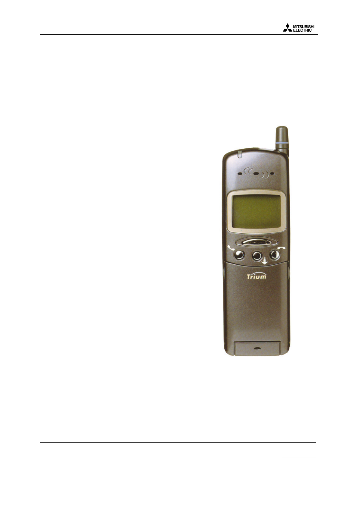
1 General Description
ARIA is designed for use in a E-GSM/DCS network. This phone operates and complies with the ETSI GSM
Phase 2 specifications.
Main features
• Weight : 85 g
• 80 hours idle time
• 1.5 hour conversation time
• Graphic LCD
• Data fax fonction included
• TEGIC fonction (word recognition)
Standart kit includes following items :
• Tranceiver (retractable antenna type)
• Battery pack (3.8V 580mA Li-ion)
Reference : FZ-2538A
• AC/DC adapter for battery rapid charging (5.5V 500mA)
Reference : FZA-0033A
Speech codec :
• ARIA uses a speech codec which
is able to switch from half rate (HR) to full rate (FR)
or to enhanced full rate (EFR) according to network and
the software & settings version.
• Enhanced full rate (EFR) allows better voice quality at
same rate as full rate.
• Half rate (HR) is coding on 6.5 kb/sec (1/2 than full rate)
the network may put two customers on one timeslot.
each customer will use this timeslot every two frames.
Actual size
Mitsubishi Electric Telecom Europe Version C
ZA le Piquet, 35370 Etrelles Date: 05/00
Phone: +33 2 99 75 71 00
Fax: +33 2 99 75 71 47
1/20
Page 5
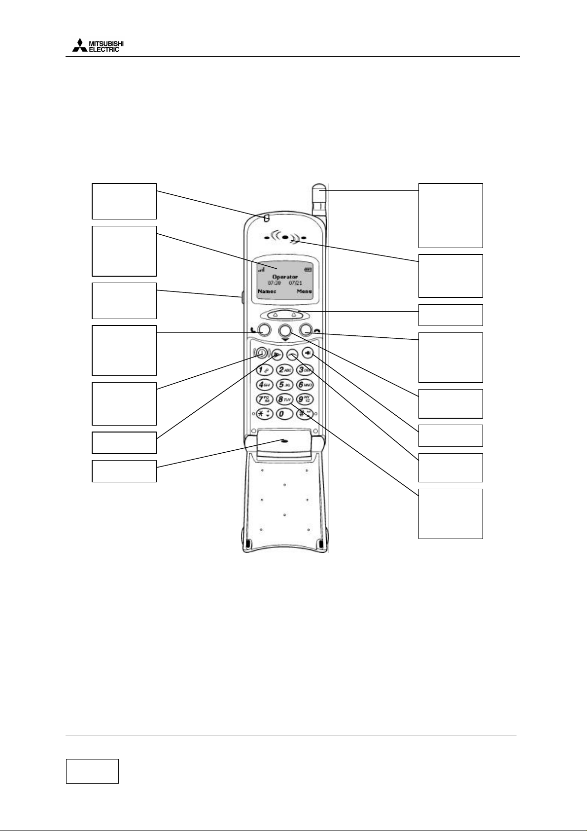
2 Main Features of Transceiver
2.a Description of transceiver
Level 2 Service Manual
ARIA
LED
Call and battery
charge indicator
Grafic display
Telephone
number, menus,
message etc. here
Headset socket
Connect the
headset here
Call/Send key
Dials displayed
number and
answers calls
On/Off key
Hold down to turn
on or off the
phone
Options key
Microphone
Retractable
antenna
Extend the
antenna fully
when sending or
receiving a call
Earpiece
You can hear the
caller’s voice here
Softkeys
End key
Press to end a call
or return to stanby
display
Multifunction
key
Volume key
TEGIC key
TEGIC on or off
Alphanumeric
keys
To enter text and
telephone
numbers
For M4 family, to enter test mode is not possible directly from mobile. This is possible only using a PC and the
relevant software .
Version C Mitsubishi Electric Telecom Europe
Date: 05/00 ZA le Piquet, 35370 Etrelles
Phone: +33 2 99 75 71 00
2/20
Fax: +33 2 99 75 71 47
Page 6
Level 2 Service Manual
ARIA
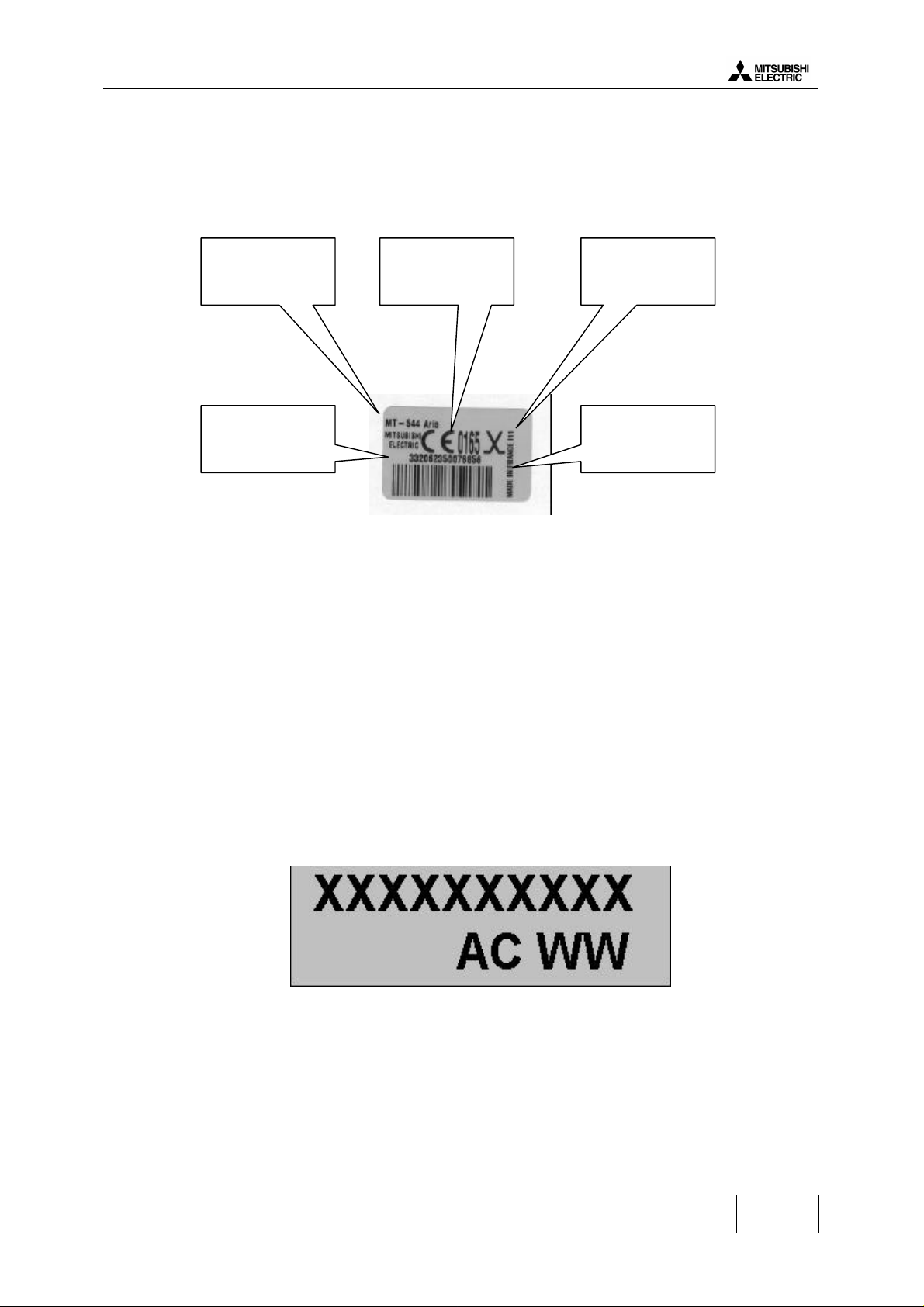
2.b IMEI label
IMEI label stands for International Mobile Equipment Identity. The IMEI label is stuck on the rear case of the
terminal. It is held in the logic circuitry of the main board itself. If the main board is changed then IMEI will
change.
Date Code is made of 3 digits and indicates the date of shipment from factory.
For example: in I11, I stands for 1999 and 11 for November (12 for december).
Bar code indicates 15 digits 123456 45 456789 4 ( for example) of the IMEI written in plain letters above the
bar code:
- 123456 : The 6 first digits indicate the Type Approval Code. It is different according the type of mobile.
- 45 : These 2 digits are allocated to production site.
- 456789 : The 6 last digits are a sequential number, it is different for each mobile.
- 4 : Check digit.
Kit designation Date code
IMEI number
and bar code
Logo Norme
Europe
Made in France
Information
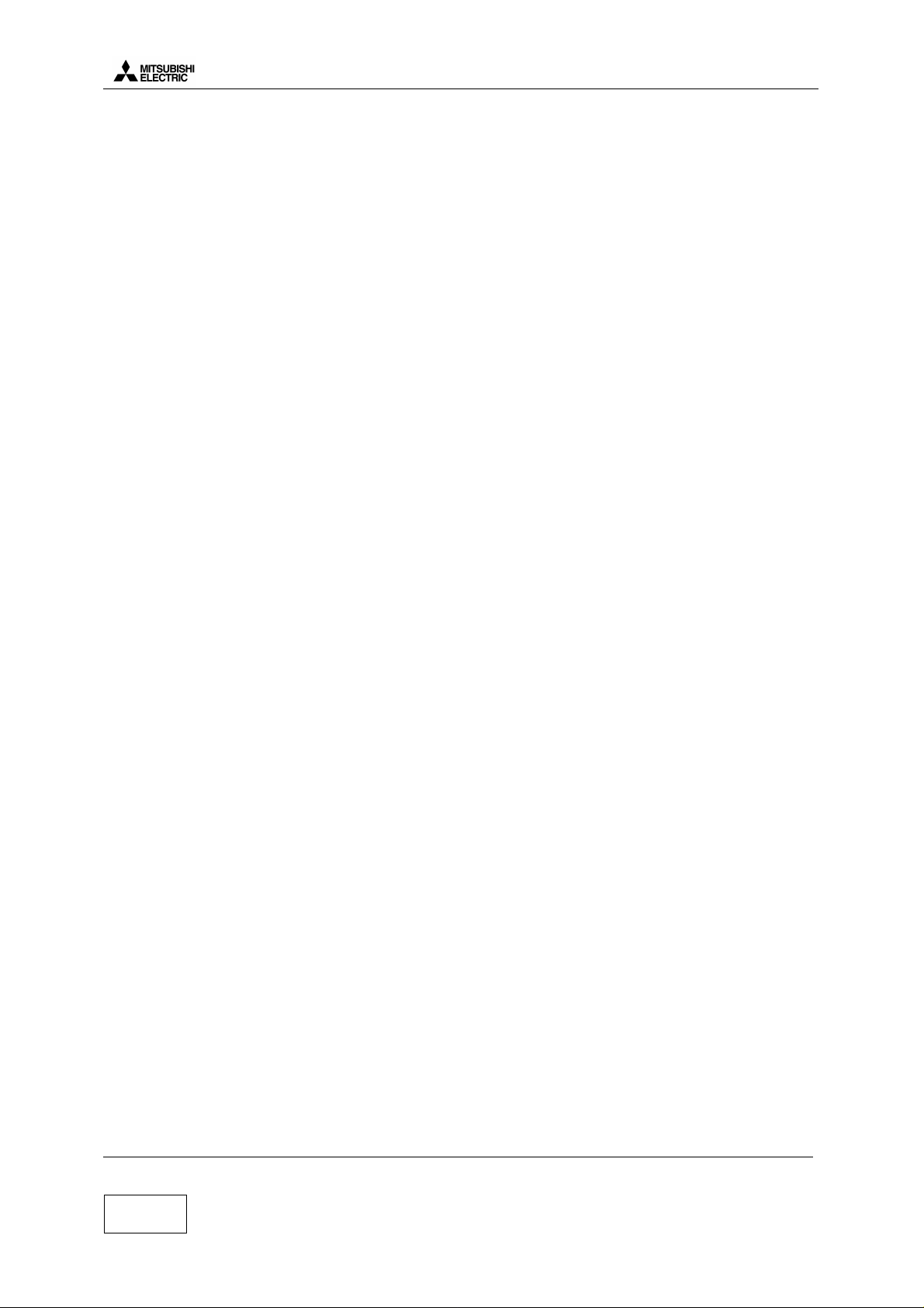
2.c ART Label
The Label Art Plate identifies the type of assembly and test the mobile has been through.
XXXXXXXXXX : 10 characters for the article code of the terminal.
A : 1 character for the assembly version of M/U.
C : 1 character for the board version.
WW : 2 characters related to production site.
Mitsubishi Electric Telecom Europe Version C
ZA le Piquet, 35370 Etrelles Date: 05/00
Phone: +33 2 99 75 71 00
Fax: +33 2 99 75 71 47
3/20
Page 7
Level 2 Service Manual
ARIA
2.d SIM Latching
SIM Lock consists in restricting the use of the terminal to a family of SIM cards. For the SIM Lock, three
principal informations are used. These informations are read from data fields in the SIM card.
1°) IMSI (International Mobile Subscriber Identity), 15 Digits :
Example of IMSI : 208 01 55 12312312
208 = MCC = Mobile Country Code (ex : 208 for France)
01 = MNC = Network Country Code (ex : 01 for FT)
55 = NS = Network Subset
12312312 = Indifferent serial number
2°) Group IDentifier 1 (GID1):
This data field can contain digits or letters which identify a family of SIM
Ex : XX for a type for of prepaid SIM card of Service provider Y
3°) Group IDentifier 2 (GID2) :
same as GID1 to identify a sub family of SIM.
Then, from this information, we have 5 types of latch :
1°) Network Level :
latch on MCC MNC of IMSI of the SIM only
(ex : only the cards 208 01 be able to operate the mobile.
Mitsubishi uses to call this latch NCK (NCK stands for “ Network Control Keys” and is the password to lock
the mobile at the network level)
2°) Network Subset Level :
Latch on MCC, MNC and digit 6 and 7 of the IMSI
Ex : latch on 208 01 55, only the SIM cards with an IMSI starting with 208 01 55 will operate the mobile.
Mitsubishi uses to call this latch NSCK (Network Subset Control Key)
3°) Service provider level :
latch on Network (value of MCC MNC) and value of GID1 data field.
Ex : latch on the value “XX” in GID1 and MCC MNC=208 01, only the SIM cards of service provider Y with
XX stored in data field GID1 will operate the mobile.
Mitsubishi uses to call this latch SPCK (Service Provider Control Key)
4°) Corporate Provider Level :
latch on network (value of MCC and MNC) and a value stored in GID2
Mitsubishi uses to call this latch CPCK (Corporate Provider Control Key)
5°) IMSI level
latch on the complete IMSI of one SIM card.
Only one SIM card corresponding to the correct IMSI operates the mobile. Usually, this latch is done in an
automatic way (the first SIM card inserted in the mobile is the only SIM which can be usesd by this mobile).
General information :
To lock /unlock a mobile, you need 8 digits password for each level concerned, and each mobile (one set of
passwords for one IMEI). These passwords are calculated with a special algorithm. You have only 10 attempts
to unlock correctly a mobile. After 10 unsuccessful attempts, the mobile is permanently blocked.
To enter the unlock procedure, you need to access special menus with specific access codes.
Version C Mitsubishi Electric Telecom Europe
Date: 05/00 ZA le Piquet, 35370 Etrelles
4/20
Phone: +33 2 99 75 71 00
Fax: +33 2 99 75 71 47
Page 8

Level 2 Service Manual
ARIA
3 EXPLODED DIAGRAM AND SPARE PART LIST
3.a Exploded Diagram of ARIA
Mitsubishi Electric Telecom Europe Version C
ZA le Piquet, 35370 Etrelles Date: 05/00
Phone: +33 2 99 75 71 00
Fax: +33 2 99 75 71 47
5/20
Page 9

Level 2 Service Manual
3.b Spare part list of ARIA
Position Designation Reference
ANTENNA 7N14153510
CAP RF F431932010
CASE ASSY V237 PEARL SILK F232909G10
COVER ASSY V237 PEARL SILK F232908G10
FLIP ARIA PEARL SILK LOGO TRIUM FK8L011610
FLIP ARIA PEARL SILK LOGO MITSUBISHI FK8L011810
CASE ASSY V237 SABLE SILK F232909G20
COVER ASSY V237 SABLE SILK F232908G20
FLIP ARIA SABLE SILK LOGO TRIUM FK8L011710
FLIP ARIA SABLE SILK LOGO MITSUBISHI FK8L011910
CUSHION-LCD F335839010
HINGE-L 1N1129701A
HINGE-R 1N1129711A
HOLDER MIC F432075010
KEY-RUBBER F233074010
LABEL ART FS2D003110
LCD MODULE 5U88338010
MIKE 7R00000070
MOTOR VIBRATOR 7T73921410
PIPE-ANT-213 F431660010
SCREW PTP1,7*5-TPR 1B79921610
SCREW PTP2,0*8-TPR-NI 1B79921410
RUBBER I/O F432010010
SHIELD BOX-F F133132G10
SHIELD BOX-R F133133010
WINDOW ARIA F233232010
EL/SW-MODULE ARIA 6R57172510
FPC ARIA F232910G10
RECEIVER 7R14377410
SPACER-SHIELD-2 F432185010
CUSHION-BB F432183010
SPACER-SHIELD-1 F432184010
SOCKET-MIC 7R11489010
CUSHION-ANT F432262010
ARIA
Connectors of ARIA
Position Designation Reference
J100 CONNECTOR I/O M4 SO 6T78676110
J101 BATTERY PROBE CONNEC 6T89736010
J200 CONNECTOR(ETP) 6T84927810
J201 CONNECTOR(ETP) 6T84927810
J300 CONNECTOR(ETP) 6T84937610
J900 CONNECTOR RF 6T25974510
Version C Mitsubishi Electric Telecom Europe
Date: 05/00 ZA le Piquet, 35370 Etrelles
Phone: +33 2 99 75 71 00
6/20
Fax: +33 2 99 75 71 47
Page 10

Level 2 Service Manual
ARIA
4 TEST AND MEASUREMENTS
4.a Charging measurements
To check the charging, we uses a modified AC/DC and an ampermeter connected as follow :
Mobile with
empty battery
without SIM
When you plug the charger into the wall socket, the charging current is displayed by ampermeter
The charging indicator scroll on the LCD and the red top led lights up.
During pre-charge, the value of the curent is 84 mA (measurment without backlight)
During rapid charge, the value of the current is 610 mA (measurment without backlight)
For more details about charging, see the LEVEL 3 SERVICE MANUAL FA9M037910 at page 5.
Mitsubishi Electric Telecom Europe Version C
ZA le Piquet, 35370 Etrelles Date: 05/00
Phone: +33 2 99 75 71 00
Fax: +33 2 99 75 71 47
7/20
Page 11

Level 2 Service Manual
ARIA
4.b E-GSM / DCS measurements
4.b.1 Transmitter Power and Ramp profile
These two are interrelated, since the power ramp shape and its final peak value is stored in EEPROM as
adjustment values.
The peak power output must lie within 3 dB of specification and be flat to within 0.5 dB over the active period.
The ramp profile is designed to give minimum harmonics, and hence it is important to ensure it is adhered to.
Power ramp profile must be checked on all frequencies (in practice channels 975, 37 and 124 for the 900 MHz
band and channels 512, 698 and 885 for the 1800 MHz band). In conclusion, the ramp must fit the mask at all
frequencies and all power levels. The mask is usually stored in the radiocommunication tester. The test will
also be available to cover the frequency and power range automatically.
4.b.2 Phase / Frequency / Time relationship
This is a test of the quality of the modulation including the IQ balance and the Gaussian filters. The phase of
the carrier changes according to the arrival of 1s and 0s. Phase error must not be more than 20° peak and 5°
RMS.
4.b.3 Receiver Bit Error Rate (RX sensitivity)
The specification is a Bit Error Rate (BER) of better than 2.44% for an input signal : -102 dBm for the E-GSM
900 band, and –100 dBm for the DCS 1800 band. There should be no error for -90 dBm to -20 dBm input
signal. The maximum workable error rate is 13%.
It is important that BER and RX sensitivity is good since measures of RXLEV (from -103 to -41 dBm) and
RXQUAL (from 0 to 7) are reported back to the base station on the SACCH to assist in handovers and power
level control. Errors in reporting will lead to sub optimum uses of channel space, or interference to others.
4.b.4 Handover between E-GSM 900 AND DCS 1800 standards
The M4 dual band may handover from the E-GSM 900 band to the DCS 1800 band automatically. If the
subscribed network has frequencies in both bands, the M4 dual band will work either in 900 MHz or 1800 MHz
band depending on the availability of frequencies.
Version C Mitsubishi Electric Telecom Europe
Date: 05/00 ZA le Piquet, 35370 Etrelles
8/20
Phone: +33 2 99 75 71 00
Fax: +33 2 99 75 71 47
Page 12

Level 2 Service Manual
ARIA
4.c Operating instructions
RADIOCOMMUNICATION TESTER
RF Cable NN 50 OHMS 0.8
(FT7Y005610)
NSMA ADAPTATOR FEMALE
ARIA RF CABLE L300
(FT7Y010410)
(FT7Y010010)
Mobile with full
battery
1. Insert Test SIM in the mobile
2. Connect a charged battery
3. Make a call with a RADIOCOMMUNICATION TESTER and check the following parameters,
or uses the autotest (CMD55 or CMD55 under MTS or Wavetek 4107)
Power levels : check the transmitted power (dBm)
E-GSM 900
PCL
Power Level
(dBm)
tolerance DCS 1800
PCL
Power level
(dBm)
5 33 +/-2dB 0 30 +/-2dB
6 31 +/-3dB 1 28 +/-3dB
7 29 +/-3dB 2 26 +/-3dB
8 27 +/-3dB 3 24 +/-3dB
9 25 +/-3dB 4 22 +/-3dB
10 23 +/-3dB 5 20 +/-3dB
11 21 +/-3dB 6 18 +/-3dB
12 19 +/-3dB 7 16 +/-3dB
13 17 +/-3dB 8 14 +/-3dB
14 15 +/-3dB 9 12 +/-4dB
15 13 +/-3dB 10 10 +/-4dB
16 11 +/-5dB 11 8 +/-4dB
17 9 +/-5dB 12 6 +/-4dB
18 7 +/-5dB 13 4 +/-4dB
19 5 +/-5dB 14 2 +/-5dB
15 0 +/-5dB
tolerance
Mitsubishi Electric Telecom Europe Version C
ZA le Piquet, 35370 Etrelles Date: 05/00
Phone: +33 2 99 75 71 00
Fax: +33 2 99 75 71 47
9/20
Page 13

Power ramping: Check the burst fit the mask below
+4+1-6
-1
-30
-70
(dB)
Level
8µS
10µS
8µS
10µS
542.8µS
147 « useful » bits
Level 2 Service Manual
ARIA
RX levels : Check the values for differents signal strenght
RX LEVEL RSSI (dBm)
0 Less than -110 dBm
1 -110 to -109
2 -109 to -108
27 -84 to -83
50 -61 to -60
62 -49 to -48
63 Better than -48
Bit error : Check the value for differents type
Check the Reception Bit Error Rates (RBER) and Frame Error Rates on channels 1,62 and 124 at –102dBm for
GSM band and on channels 512, 698 and 885 for the DCS band according the following specifications :
Bit error type Value
RBER Class Ib < 0.41 %
RBER Class II < 2.44 %
FER < 0.12%
4.d Buzzer and Speaker tests
Insert a test SIM in mobile set with battery.
The volume levels of the ring tone, key tones and incoming audio can be individually adjusted in the setting
menu.
• Press Menu choose Settings by pressing and validate by pressing for Select
• Choose Tones by pressing and validate by pressing for Select
• Choose Volume by pressing and validate by pressing for Select
And adjust Ring and Conversation to check buzzer and speaker
Version C Mitsubishi Electric Telecom Europe
Date: 05/00 ZA le Piquet, 35370 Etrelles
Phone: +33 2 99 75 71 00
10/20
Fax: +33 2 99 75 71 47
Page 14

Level 2 Service Manual
ARIA
5 Service SOFTWARES
The software in the mobile consist of two files downloaded independantly.
The corp of this software is downloaded using IPLTrium.
The settings file (ringing, customization…) is downloaded with MS Tools. MS tools also allows to enter test
mode in order to reset usesr data (security code) , to print labels (imei & factory name plate), to reset the
permantly blocked indicator providing you have the access rights.
5.a Software download with IPLTrium
5.a.1 How to install IPLTrium software and equipment
Equipment description :
Mobile without battery
To COM1
PC Cable S4 & D
FK8L011110
AC/DC
FZA0033A
IPL trium is available on Windows 95, 98, NT4 OS and is made of differents files :
(These files can be provided under one ZIP file)
To install IPLTRIUM software, create a folder named M4_soft_aria
And copy the files into this folder. In this folder, create two new folders named Software and Setting
In the Software folder, copy the software file (*.BIN) available for the mobile you have to download.
You are now ready to download the software.
Mitsubishi Electric Telecom Europe Version C
ZA le Piquet, 35370 Etrelles Date: 05/00
Phone: +33 2 99 75 71 00
Fax: +33 2 99 75 71 47
11/20
Page 15

5.a.2 Software description
Level 2 Service Manual
ARIA
Click here to adjust
Serial Parameters
Progress Indicator
Information Window
Adjust the serial parameters as folowing
Version C Mitsubishi Electric Telecom Europe
Date: 05/00 ZA le Piquet, 35370 Etrelles
12/20
Phone: +33 2 99 75 71 00
Fax: +33 2 99 75 71 47
Page 16

Level 2 Service Manual
ARIA
5.a.3 Start download
Click here to select the
Sofware for download
Click here to select
Flash Loader
(iplm4so.bin for aria (SOcial))
Click here to
Startdownload
5.a.4 End of Download
When download is completed, press the mobile Power key (mobile shuts down), disconnect the ARIA PC
Cable, connect a full battery and press the power key (mobile switches on).
Mitsubishi Electric Telecom Europe Version C
ZA le Piquet, 35370 Etrelles Date: 05/00
Phone: +33 2 99 75 71 00
Fax: +33 2 99 75 71 47
13/20
Page 17

5.b Settings download with MS Tools
5.b.1 How to install MS Tools software and equipment
Equipment description :
Level 2 Service Manual
ARIA
Mobile with full battery
To COM1
MS Tools is available on Windows 95, 98, NT4 OS and to install it you need theses 3 files :
Setup procedure :
1 Launch Setup.exe
2 Click on Finish
3 Click on OK
PC Cable S4 & D
FK8L011110
MS Tools is now installed on your computer and available in your START menu
You are now ready to download the setting file.
Version C Mitsubishi Electric Telecom Europe
Date: 05/00 ZA le Piquet, 35370 Etrelles
14/20
Phone: +33 2 99 75 71 00
Fax: +33 2 99 75 71 47
Page 18

Level 2 Service Manual
ARIA
5.b.2 Software description
Exit:
To quit MS Tools
(Click on is not availlable)
Mobile menu :
Download perso
Initialization data users
Mobile identification
Test Mode menu :
TEST MODE enter and exit
Informatio
n window
Version of
MS Tools
5.b.3 Start download
In TestMode menu, click on Start from NormalMode, then information window displays Operation completed
Informatio
n window
Mitsubishi Electric Telecom Europe Version C
ZA le Piquet, 35370 Etrelles Date: 05/00
Phone: +33 2 99 75 71 00
Fax: +33 2 99 75 71 47
15/20
Page 19

Level 2 Service Manual
In Mobile menu, click on Download Personification, then, choose the right settings file and valid by select
ARIA
information window displays Operation completed
Informatio
n window
Version C Mitsubishi Electric Telecom Europe
Date: 05/00 ZA le Piquet, 35370 Etrelles
16/20
Phone: +33 2 99 75 71 00
Fax: +33 2 99 75 71 47
Page 20

Level 2 Service Manual
ARIA
5.b.4 End of download
In TestMode menu, choose Stop and go back to NormalMode, then information window displays Operation
completed
Informatio
n window
Mitsubishi Electric Telecom Europe Version C
ZA le Piquet, 35370 Etrelles Date: 05/00
Phone: +33 2 99 75 71 00
Fax: +33 2 99 75 71 47
17/20
Page 21

Level 2 Service Manual
5.c How to print labels using MS Tools
5.c.1 Equipment, Software and drivers required
Equipment description: mobile with battery
COM1
COM2
ZEBRA
90XiII
ARIA
Printer
Software required : MS tools
MS Tools software version 4.01 (or higher) is required to print labels.
This software is provided by MITSUBISHI ELECTRIC France under floppy format (2 floppies)
MS Tools is available on Windows 95, 98, NT4 OS and to install it you need theses 3 files:
Setup procedure:
1 Launch Setup.exe
2 Click on Finish
3 Click on OK
MS Tools is now installed on your computer and available in your START menu
MS tools program does not send information directly to ZEBRA 90Xi II printer, it sends information to NI
VISA driver and NI VISA driver sends information to ZEBRA 90Xi II printer.
Driver required: NI VISA
NI VISA driver is required and can be provided by MITSUBISHI ELECTRIC France.
The NI VISA driver is located on NATIONAL INSTRUMENTS NI 488.2 CD-ROM
To install this driver on your PC, launch the setup.EXE which is located in the NI-VISA folder on the CDROM.
Version C Mitsubishi Electric Telecom Europe
Date: 05/00 ZA le Piquet, 35370 Etrelles
18/20
Phone: +33 2 99 75 71 00
Fax: +33 2 99 75 71 47
Page 22

Level 2 Service Manual
Labelart
IMEI Label
ARIA
5.c.2 Print labels
In TestMode menu, choose Start from NormalMode, then Mobile menu became available.
In Mobile menu, choose Mobile identification, and then following screen will be displayed.
Click here
to print an
Click here
to print a
Mitsubishi Electric Telecom Europe Version C
ZA le Piquet, 35370 Etrelles Date: 05/00
Phone: +33 2 99 75 71 00
Fax: +33 2 99 75 71 47
19/20
Page 23

Level 2 Service Manual
ARIA
6 SOFTWARE AND SETTING VERSION
To display the software and the perso (personalisation), connect a charged battery, press the power key. Wait a
few seconds, then hold the * key and press 5807.
Then on the mobile, the following message is displayed
For example:
To exit from the Software and Perso monitoring mode, press any key except power key
- - VERSION - - 21157001
- - - PERSO - - - 21433S00
7 OPERATOR DEBUGGING
To display the RX level (in dBm), insert the SIM card (from service provider or test SIM card using CMD in
manual test) , connect a charged battery and press the power key. When the mobile displays the network (real
network or test network 001-01) ,hold the * key and press 4329
Then on the mobile, the following message is displayed
For example : RX level (dBm)
B099 07 -085
MCC001 MNC01
1.a.1.1.1.1.1.1 And
other
datas
To exit from the Operator debugging mode, uses the same command : hold the * key and press 4329
Mitsubishi Electric reserves the right to make changes to its products at any time to improve reliability or
manufacturability. Mitsubishi Electric does not assume any liability arising from the uses of any device or
circuit described herein, nor does it convey any license under its patent rights or the rights of others.
Version C Mitsubishi Electric Telecom Europe
Date: 05/00 ZA le Piquet, 35370 Etrelles
20/20
Phone: +33 2 99 75 71 00
Fax: +33 2 99 75 71 47
 Loading...