

Page 1

OWNER'S HANDBOOK
XEN Pentium
apricot
MITSUBISHI ELECTRIC
Page 2

OWNER'S HANDBOOK
Chapter
Page 3

Microsoft, MS, and MS-DOS are registered trademarks, and Windows is a trademark, of Microsoft
Corporation.
IBM is a registered trademark, and VGA and PS/2 are trademarks, of International Business
Machines Corporation.
Intel is a registered trademark, and Pentium and OverDrive are trademarks, of Intel Corporation.
Information contained in this document is subject to change without notice and does not
represent a commitment on the part of Apricot Computers Limited. Any software described in
this manual is furnished under a license agreement. The software may be used or copied only in
accordance with the terms of this agreement. It is against the law to copy any disk supplied for any
purpose other than the purchaser’s personal use.
All rights reserved; no use or disclosure without written consent.
Copyright © Apricot Computers Limited 1994
Published by
Apricot Computers Limited
3500 Parkside
Birmingham Business Park
Birmingham B37 7YS
MITSUBISHI ELECTRIC
Printed in the United Kingdom
Part No. 15445731
Revision 01
Page 4

Safety and Regulatory Notices
Safety and Regulatory Notices
Read the separate Power Connection Guide before using your
computer for the first time. Information in the Owner’s Handbook
relating to connection to the AC power supply may not apply
outside the United Kingdom.
Your computer uses a safety ground and must be earthed. The
system unit AC power cord is its “disconnect device”. Ensure
that the system unit is positioned close to the AC power outlet,
and that the plug is easily accessible.
It is imperative that the computer is set to the correct voltage
range before use. If not, the machine may be irreparably damaged.
Turn off the computer and unplug all power cords before moving
the system unit, cleaning the computer or removing the system
unit top cover.
The CD-ROM drive contains a laser system which is harmful to
the eyes, and is classified as a CLASS 1 LASER PRODUCT
according to IEC 825 Radiation Safety of Laser Products (Equipment
Classification: Requirements & User's Guide). Do not attempt to
disassemble the CD-ROM drive; if a fault occurs, call an
authorized maintainer. Use the CD-ROM drive only as described
in this manual; failure to do so may result in exposure to
hazardous radiation.
Safety
To prevent fire and electric shock, do not expose any part of
the system unit to rain or moisture.
When positioning the system unit, monitor and keyboard, take
into account any local or national regulations relating to
ergonomic requirements.
XEN OWNER'S HANDBOOK I
Page 5
Safety and Regulatory Notices
Power cord The power cord packed with the computer complies with
requirements the safety standards applicable in the country in which it is sold.
Use only this power cord; do not substitute a power cord from
any other equipment.
Safety
If you wish to use the computer in another country, you must
ensure that you use a power cord and plug which complies with
the safety standards of that country.
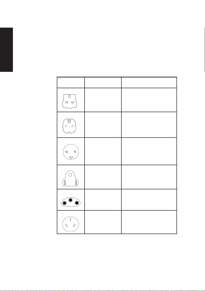
Plug Standard Countries
250V
E
LN
250V
E
NL
250V
N
E
125V
E
N
250V
L
L
BS1363A United Kingdom
Austria, Belgium, Finland,
SHUCO France, Germany, Holland,
Italy, Norway, Sweden
SRAF 1962/ Denmark
DB16/87
NEMA 5-15P USA, Canada
ASE 1011 Switzerland
250V
The power cord fittings must bear the certification mark of the
agency responsible for evaluation.
Refer to your authorized supplier if you ever require additional
or alternative power cables.
II XEN OWNER'S HANDBOOK
AS 3112-1981 Australia
Page 6
Safety and Regulatory Notices
UK plug wiring instructions
IMPORTANT Power
Cable Connections
This appliance is supplied with a mains lead that
has a non-removable moulded plug. If the socket
outlets are not suitable for the plug supplied with
this appliance, it should be cut off and an
appropriate three-pin plug fitted.
Note: The plug severed from the mains lead must
be destroyed, as a plug with the bared flexible
cord is hazardous if engaged in a live socket
outlet.
The following wiring information should be
employed when adding the replacement plug.
The wires in the mains lead are coloured in
accordance with the following code:
Green and Yellow Earth
Blue Neutral
Brown Live
As the colours of the wires in the mains lead of
this appliance may not correspond with the
coloured markings identifying the terminals in
your plug, proceed as follows.
The wire which is coloured green-and-yellow
must be connected to the terminal in the plug
which is marked with the letter E, or by the earth
symbol or coloured green or green-andyellow.
The wire which is coloured blue must be connected
to the terminal which is marked with the letter N or
coloured black. The wire which is coloured brown
must be connected to the terminal which is marked
with the letter L or coloured red.
Use a fuse approved by ASTA to BS1362, i.e.
ASA
carries the
Always replace the fuse cover, never use the plug
with the fuse cover omitted.
Replace with same colour fuse cover only.
Replacement fuse covers may be obtained from
your dealer.
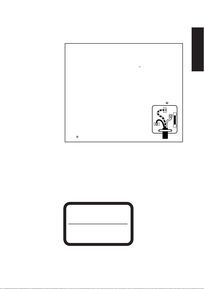
WARNING THIS APPLIANCE MUST BE
EARTHED
This diagram
shows the wiring
inside the moulded
plug. Use it as a
guideline if you
need to re-fit a plug
of a similar type to
the mains lead.
mark.
E
N
Safety
L
Noise levels German Acoustic Noise Regulation
Sound power level is less than 70 dB(A) according to DIN
45635 Part 19 (ISO 7779).
Die Deutsche Akoustische Lärm-Regulierung
Der Grad der Klangstärke ist weniger als 70 dB(A) je nach DIN
45635 Teil 19 (ISO 7779).
CLASS 1
LASER PRODUCT TO IEC 825
LASER KLASSE 1
PRODUKT NACH IEC 825
XEN OWNER'S HANDBOOK III
The CD-ROM drive is
classified as a CLASS 1
LASER PRODUCT.
The CLASS 1 LASER
PRODUCT label is
located on the under
side of the system unit.
Page 7

Safety and Regulatory Notices
Refer to the labels on the rear of your computer to establish which of the following warnings
apply.
FCC Class A
Warning - this equipment has been tested and found to comply with the limits for a Class A
computing device, pursuant to Subpart J of Part 15 of FCC rules. Only peripherals (computer
input/output devices, terminals, printer, etc.) certified to comply with the Class A limits may be
Safety
attached to this computer. Operation of this equipment in a residential area may cause
unacceptable interference to radio and television reception requiring the operator to take
whatever steps are necessary to correct the interference.
FCC Class B
Warning - this equipment has been certified to comply with the limits for a Class B computing
device, pursuant to Subpart J of Part 15 of FCC rules. Only peripherals (computer input/output
devices, terminals, printer, etc.) certified to comply with the Class B limits may be attached to this
computer. Operation with non-certified peripherals is likely to result in interference with radio
and TV reception.
Radio and television interference
The computer described in this manual generates and uses radio frequency energy for its
operation. If it is not installed and used properly, in strict accordance with the manual, it may
cause interference with radio and television reception.
The computer has been tested and found to comply with the RF emission limits for an FCC Class
B computing device which is intended to provide reasonable protection against such interference
in a residential installation. However, there is no guarantee that interference will not occur in a
particular installation.
If this equipment does cause interference with radio or television reception, which can be
determined by turning the equipment off and on, the user is encouraged to try to correct the
interference by one or more of the following measures:
• Move the computer away from the receiver being interfered with.
• Turn the computer with respect to the receiver.
• Turn the receiver with respect to the computer.
• Plug the computer into an outlet that is on a different branch circuit from the receiver.
• Disconnect and remove any I/O cables that are not being used.
• Unplug and remove any expansion cards that are not being used, and replace the relevant
blanking plates.
• Make sure that the computer is plugged into a grounded outlet.
If you need additional help, consult your supplier. You may find the following booklet helpful: How
to Identify and Resolve Radio-TV Interference Problems. This booklet is available from the US
Government Printing Office: Washington DC 20402 - Stock No. 004-000-000345-4.
DOC Class A
The computer described in this manual complies with: Canadian DOC radio interference
regulations CRCc 1374 governing Class A digital devices.
DOC Class B
The computer described in this manual complies with: Canadian DOC radio interference
regulations CRCc 1374 governing Class B digital devices.
IV XEN OWNER'S HANDBOOK
Page 8

CONTENTS
Chapter
Page 9

CONTENTS
1 Introducing your computer
2 Getting started with your computer
Contents
General advice 2/2
Connecting the components 2/3
Turning on and booting the computer 2/4
Preparing a second hard disk 2/6
The software on your computer 2/7
Using the SETUP utility 2/8
Using Help 2/9
3 Operating your computer
Using the front panel controls 3/2
Using the 3.5" diskette drive 3/3
Using the 5.25" floppy disk drive 3/4
Using a CD-ROM drive 3/6
Using the FTD tape drive 3/11
Using the SCSI QIC tape drive 3/13
Using the SCSI DDS-DC tape drive 3/16
Using your computer abroad 3/21
4 SETUP
Introduction 4/1
Invoking SETUP 4/1
The opening screen 4/2
Using SETUP 4/4
SETUP runs automatically 4/5
System summary 4/5
Devices and I/O ports 4/6
Date and time setup 4/10
System security 4/10
Start options 4/13
Contents
XEN OWNER'S HANDBOOK I
Page 10

Contents
Advanced SETUP 4/15
ISA Legacy Resources 4/17
Power management 4/18
Error messages 4/20
5 Expanding the system
Expansion cards 5/2
Memory upgrades 5/6
Processor upgrades 5/10
Installing additional video RAM 5/13
5.25" drives 5/15
Contents
3.5" hard disk drive 5/21
6 Caring for your computer
Cleaning your computer 6/2
Transporting your computer 6/6
7 Troubleshooting
Problems when starting 7/2
Checklist 7/4
A Appendix - Inside your computer
Anti-static precautions A/2
Removing the top cover A/3
Configuring expansion cards A/4
Motherboard jumper settings A/14
B Appendix - Technical Information
Specifications B/2
Physical characteristics B/6
Electrical characteristics B/6
Port characteristics B/8
II XEN OWNER'S HANDBOOK
Page 11
INTRODUCING YOUR COMPUTER
Chapter 1
Chapter
Page 12

Introducing your computer
1 INTRODUCING YOUR
COMPUTER
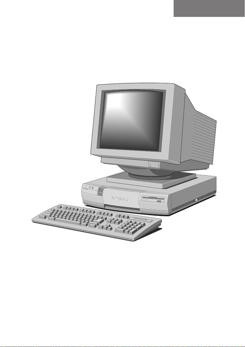
The Apricot XEN Pentium range is ideally suited for use as
a general-purpose personal computer, networked business
workstation or workgroup server.
Read the separate Power Connection Guide before
using your computer for the first time.
Chapter 1
XEN OWNER'S HANDBOOK 1/1
Page 13

Introducing your computer
Standard features
Standard features of the range include:
• Intel Pentium system processor.
• Standard 8 Mbytes of motherboard random access
• Second level system memory cache (at least
• On-board high performance PCI bus video based on
• PCI Integrated Drive Electronics (IDE) hard disk drive
• Fast graphic boot option with SETUP configuration
• Full power management.
memory (RAM), upgradable to 128 Mbytes by the use
of single in-line memory modules (SIMMs).
256kbytes).
a Cirrus Logic GD543X controller, equipped with at
least 1 Mbyte of video RAM, upgradeable to 2 Mbytes.
interface.
utility in read-only memory (ROM).
Chapter 1
1/2 XEN OWNER'S HANDBOOK
• Two full-length, one half length 16-bit Industry
Standard Architecture (ISA) expansion card slots and
one full length PCI slot.
• ISA IDE drive interface for use with an ATA-PI CD-
ROM drive.
• Extended keyboard with microphone mount; two-
button mouse, parallel and dual serial ports.
• 1.44 Mbyte 3.5" diskette drive; 3.5" hard disk drive
bay with room for two one-inch drives; one 5.25"
removable media drive bay.
These standard features can be enhanced by more memory,
various hard disk and removable media drives, adapter
cards, and so on. For an outline of these options, see
Chapter 5, “Expanding the system”.
Page 14

Unpacking
Introducing your computer
On unpacking the computer, you should find:
• System unit.
• Monitor and accompanying User’s Guide.
• Extended keyboard and two-button mouse.
• System unit AC power cord and monitor power cord
appropriate for the country of sale.
• System documentation (Owner’s Handbook, Warranty
Pack, and so on).
• Microsoft MS-DOS pack.
• Microsoft Windows for Workgroups pack (if the system
has a hard disk).
• Two caselock keys.
More elaborate systems may include software or hardware
options with accompanying installation diskettes and
additional documentation. Some of these options may have
been factory-configured or installed by your supplier.
Chapter 1
Keep the cartons, boxes and packaging materials; you will
need them again if you have to transport the computer
elsewhere.
Make a note of the manufacturer’s data recorded on the
various components (product codes, serial numbers, etc.).
You may need this information if the computer develops a
fault. In particular, note the serial number stamped onto the
caselock keys, in case they get lost and need to be replaced.
Instructions for removing the top cover are given in
Appendix A, “Inside your computer”.
Turn off the computer and unplug all power cords
before removing the top cover.
XEN OWNER'S HANDBOOK 1/3
Page 15
Introducing your computer
5
4
Chapter 1
1/4 XEN OWNER'S HANDBOOK
3
1
2
Page 16

Introducing your computer
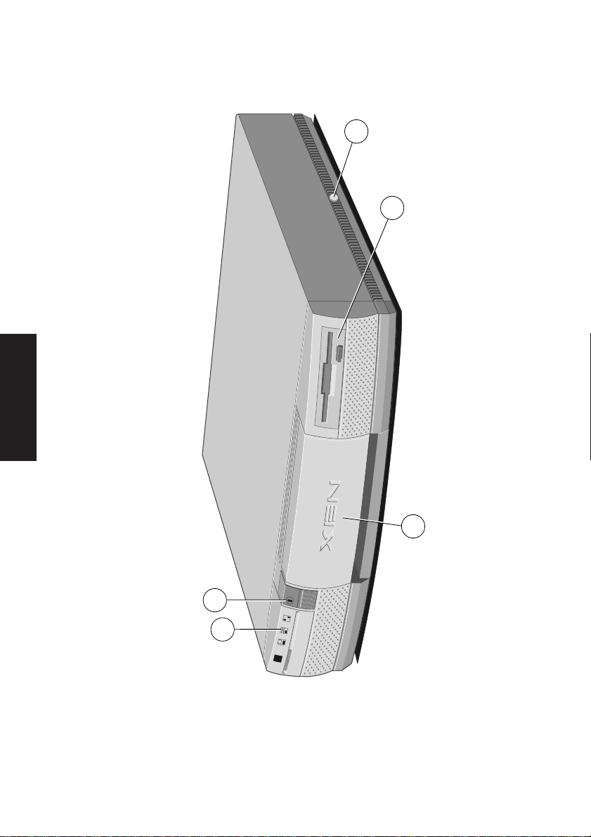
1 POWER button: press to turn the system on or off.
The green indicator on the button lights when the
system unit is powered.
2 activity indicators, from left to right:
lights when a diskette, floppy disk or floppy tape
drive is accessed (depending on the operating system).
lights when a hard disk drive or SCSI tape drive
is accessed (depending on the operating system).
3 door (shown closed): hinges down to reveal the
removable-media drive bay.
4 3.5" diskette drive: fitted as standard.
5 top cover caselock: the caselock secures the system
unit top cover; keep the keys for this lock in a secure
place.
Chapter 1
XEN OWNER'S HANDBOOK 1/5
Page 17
Introducing your computer
11
12
10
1
3
9
10
2
4
5
6
7
8
13
Chapter 1
1/6 XEN OWNER'S HANDBOOK
Page 18

Introducing your computer
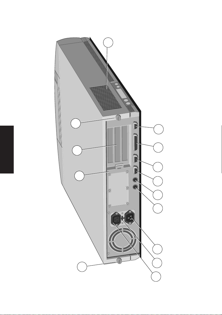
1 AC power outlet: where the monitor power cord
can plug in. Only manufacturer-approved monitors
should be powered from this outlet.
2 voltage selection switch: the computer can be
set to operate with a 100-120 volt or 220-240 volt
AC power supply.
3 AC power inlet: where the system unit AC power
cord plugs in.
4 keyboard port: connect the keyboard to this port.
5 mouse port: connect the mouse to this port.
6 serial port 1 (50 baud to 19,200 baud): typically
used for connecting an external modem or a serial
printer signal cable.
7 serial port 2 (50 baud to 19,200 baud): typically
used for connecting an external modem or a serial
printer signal cable.
8 parallel port: typically used for a printer signal
cable. Supports ECP and EPP.
Chapter 1
9 monitor port: connect the monitor signal cable to
this port.
10 casing screws: loosen these to remove the top
cover.
11 security loop: you can feed a security chain or cable
through this loop and secure it to prevent theft of
the system unit.
12 blanking plates: for expansion card slots.
13 air vent: do not block this vent or the system will
overheat.
XEN OWNER'S HANDBOOK 1/7
Page 19
Introducing your computer
1
2
3
6
4
Chapter 1
5
7
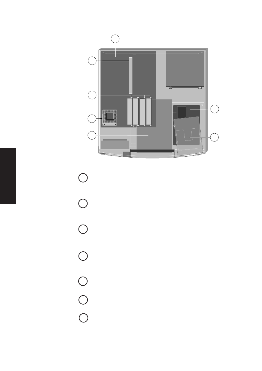
1 motherboard: see the label inside the system unit
top cover for up-to-date information on the layout
of the motherboard.
2 expansion card slots: Three expansion slots, one
half length and one full length ISA, and one full length
slot which can be used by either an ISA or PCI card.
3 SIMM sockets: every system is fitted with at least 8
Mbytes of memory which can be upgraded to 128
Mbytes by the use of single in-line memory modules.
5 processor socket: replace the existing processor
with a suitable OverDrive processor here to upgrade
the processing power of your computer.
4 5.25" removable-media drive bay: may be
occupied by a removable media drive.
6 3.5" hard-disk drive bay: this bay has room for two
one-inch high IDE hard disk drives.
7 3.5" diskette drive: fitted as standard.
1/8 XEN OWNER'S HANDBOOK
Page 20

GETTING STARTED WITH YOUR COMPUTER
Chapter
Chapter 2
Page 21

Getting started with your computer
2 GETTING STARTED WITH YOUR
COMPUTER
You should read this chapter even if you do not read any
other. It provides important information to help you site,
connect, power and configure your computer.
If you are familiar with the operation of personal computers,
this chapter will probably tell you all you need to know in
order to start working with your computer. Chapter 3,
“Operating your computer”, has more information about the
use of the various disk and tape drives which may be fitted
in the system.
Read the separate Power Connection Guide before
using the computer for the first time.
XEN OWNER'S HANDBOOK 2/1
Chapter 2
Page 22

Getting started with your computer
General advice
The computer is designed to be used in a normal office
environment. Here are a few hints for choosing a suitable
site:
• Place the system unit flat on a sturdy, level surface.
Unlike some other computers, the system unit is not
designed to be stood on its side.
• Site the system away from moisture, direct sunlight,
and extremes of heat and cold. Avoid situations in
which the surrounding temperature or humidity may
change rapidly. See Appendix B, “Technical
Information”, for recommended temperature and
humidity ranges.
• When positioning the system unit, monitor and
keyboard, take into account any local or national
regulations relating to ergonomic requirements. For
example, you should ensure that little or no ambient
light is reflected off the monitor screen as glare, and
that the keyboard is placed in a comfortable position
for typing.
Chapter 2
2/2 XEN OWNER'S HANDBOOK
• Give the system plenty of room so that air can
circulate on all sides. Air is drawn into the system unit
through the vent on the left-hand side. Ensure that
this vent is never obstructed.
• Do not allow any cables, particularly power cords, to
trail across the floor where they can be snagged by
people walking past.
The computer uses the system unit AC power cord
as its “disconnect device”. Ensure that the system
unit is positioned close to the AC power outlet, and
that the plug is easily accessible.
To prevent fire and electric shock, do not expose any
part of the system unit to rain or moisture.
Page 23

Getting started with your computer
Connecting the components
See Chapter 1, “Introducing your computer”, if you need
help identifying the various ports on the system unit.
Checking the AC power supply
When your computer is delivered, it is ready for the
commercial AC power supply generally available in the
country in which it is sold. It has been set for the correct
voltage range, and is supplied with an AC power cord and
plug which comply with the relevant safety standards.
Before using your computer in a country other than the one
in which it was originally sold, you must check the voltage
and frequency of that country’s AC power supply, and the
type of power cord required there.
If necessary, the AC voltage setting of the system can be
adjusted by the voltage selection switch on the rear of the
system unit (see the section on “Using the computer abroad”
in Chapter 3, “Operating your computer”). Note that the
monitor’s voltage setting will probably also need adjusting;
consult the User’s Guide that accompanies the monitor, or
ask your supplier for help.
Chapter 2
The “Safety and Regulatory Notices” section at the start of
this manual includes advice about suitable power cords.
Installing add-on options
If your computer arrived with uninstalled add-on options,
(such as expansion cards or memory modules) consult
Chapter 5 “Expanding the system” for step-by-step
instructions for installing them. Expansion cards may also
have their own documentation.
Note that some options for which you have installation
guides may have already been installed for you at the factory
or by your supplier.
XEN OWNER'S HANDBOOK 2/3
Page 24

Getting started with your computer
Connecting the components
Having assured yourself that the voltage settings and the AC
power cords of the computer, the monitor and any other
peripherals are correct:
1. If your AC power outlets have switches, set them
to their Off positions.
2. Ensure that the system unit, the monitor, and any
peripherals are turned off.
3. Connect signal cables and power cords (in that
order) to their respective ports and inlets on the
system unit, the monitor, and any peripherals. Make
sure the cables are connected securely.
When you plug the keyboard cable into the rear of
the system, be careful not to plug it into the mouse
port by mistake.
4. Connect the system unit and peripheral power
cords to nearby, grounded AC power outlets.
5. If your AC power outlets have switches, set them
to their On positions.
Your computer is now ready to use. The rest of this chapter
tells you how to turn your computer on and off, and how
to configure it using the built-in SETUP utility.
Turning on and booting the computer
Chapter 2
Turning the power on
To turn on the computer, simply press the POWER button.
The green indicator on the POWER button lights to show that
the system unit is powered. Remember that the monitor
has its own power control; see the monitor’s User’s Guide
for details.
Always make sure that the system is turned on before
turning on any attached peripherals.
2/4 XEN OWNER'S HANDBOOK
Page 25

Power-on self-test
Whenever the computer is turned on, the power-on selftest (POST) routine tests various hardware components,
including memory, and checks the computer’s configuration.
During this time, various BIOS sign-on and POST messages
are displayed, and you have the opportunity of invoking the
built-in SETUP utility to reconfigure the computer
(described later in this chapter).
The boot sequence
Provided that POST succeeds without discovering any
serious errors or configuration discrepancies, the computer
attempts to find an operating system; that is, it attempts
to boot. By default, it will first look for a system diskette,
then for a bootable hard disk partition.
Turning the power off
When you have finished using the system and want to turn
it off, be sure that any information you want to keep is
stored on a diskette or on a hard disk. Any information held
in the computer’s system memory will be lost when you
turn off the computer.
Always turn off any attached peripherals first.
Getting started with your computer
Chapter 2
If you are logged-in to a network, log out before turning off
the computer. Similarly, close down or exit from any
software which employs virtual memory or disk-caching (for
example, Microsoft Windows v3.1x with SMARTDrive).
Do not turn off the computer if any of the activity indicators
on the front panel are lit; this means that the computer is
accessing a drive. Wait until that operation is completed
before turning off the computer.
XEN OWNER'S HANDBOOK 2/5
Page 26

Getting started with your computer
To turn off the computer, simply press the POWER button again.
The green indicator on the button goes out. (Remember that
the monitor is powered from the system unit.)
After you turn the computer off, wait at least 5 seconds before
turning it on again. The computer may not initialize itself
properly if you turn it off then on again in quick succession.
Preparing a second hard disk
Some computers have two hard disk drives, known as
master and slave.
The master drive is partitioned, formatted and has Microsoft
MS-DOS installed at the factory. The drive is given a single
primary DOS partition, which is the active partition. When
you turn the computer on, it will boot (load its operating
system) from the master drive, which will appear as MS-DOS
drive C.
The slave drive is not partitioned or formatted. You must
partition the slave drive with the MS-DOS Fdisk program,
and format the partitions with the Format command. Until
you do this, you will be unable to use the slave drive. See
your MS-DOS manual for instructions on using Fdisk and
Format.
Chapter 2
2/6 XEN OWNER'S HANDBOOK
Caution: When you run Fdisk, it assumes you want to
work with the first, or master, drive (it says the “Current
fixed disk drive” is “1”). To switch attention to the slave
drive, choose Select next fixed disk drive (option 5) from
the main menu.
Of course, you may also want to use Fdisk to repartition
the master drive. If you decide to do this, be sure to make
a back up copy of all the information on the drive first,
including MS-DOS itself, as repartitioning will cause the
master drive’s existing contents to be lost.
Page 27

Getting started with your computer
The software on your computer
All computers with a hard disk arrive with Microsoft MSDOS and Microsoft Windows for Workgroups pre-installed.
Other software may be pre-installed at the factory or by your
supplier.
Hard disks also contain a copy of the Windows display driver
for the video subsystem, but Windows is factory configured
to use the standard VGA driver. For instructions on changing
the Windows display setup refer to the CL543X help file
within Windows.
In addition to a working copy of MS-DOS, Windows and the
Windows display driver, your hard disk will contain images
of the DOS and Windows installation diskettes, and any
drivers diskettes for your computer. A Windows utility is
provided to allow you to create copies of these diskettes.
This utility is run whenever you start Windows.
You will need a copy of the display driver diskettes should you
wish to install a display driver for a non-Windows
application. Refer to the CL543X help file in Windows for
information on the drivers and utilities supplied.
Chapter 2
Copies of the DOS and Windows diskettes will safeguard
against hard disk failure, or accidental overwriting or
deletion of files. It is recommended that you use the utility
to create copies of the diskettes soon after setting up your
system.
XEN OWNER'S HANDBOOK 2/7
Page 28

Getting started with your computer
Using the SETUP utility
What is SETUP?
SETUP is a configuration utility programmed into the
motherboard’s read-only memory (ROM). Because it is
permanently kept in ROM, SETUP does not need an
operating system to function and can be invoked whenever
you turn on or reboot your computer.
SETUP’s purpose is to allow you to view and alter your
computer’s configuration. To configure a computer means
to declare its hardware components, such as the amount
of memory it has or the type of monitor, and to say how
you want them to be used. Configuring your computer is
often necessary to ensure that the software you use can
recognise and exploit the system’s capabilities.
The configuration data is kept in a special part of the
computer’s memory, known as configuration memory or
CMOS memory. This memory is sustained by a small
battery, so its contents are preserved while the computer
is turned off.
Chapter 2
Invoking SETUP
2/8 XEN OWNER'S HANDBOOK
Your computer arrives preconfigured, but may need to be
reconfigured after you add or remove add-on options such
as memory modules or expansion cards. Refer to Chapter
4 “SETUP” for more information.
Each time the computer is turned on or rebooted, it runs
through a power-on self-test (POST) routine. During this,
the SETUP utility can be invoked by pressing the F1 key.
Once you have pressed F1, the SETUP utility usually starts as
soon as POST is completed (if your computer has a lot of
memory to test, this may take several seconds). However, if
the power-on password feature is enabled, you must enter
the password correctly before SETUP will start.
Page 29

Getting started with your computer
Using Help
Along with the diskettes provided with your computer, or
the software preinstalled on its hard disk, you will often find
one or more Help files. These will explain any special features
of the system, and tell you how to install the software needed
to exploit those features.
Help may be supplied in various forms, depending on the
intended operating system; in the MS-DOS/Windows
application environment they are usually windows help files
or ASCII text files.
Viewing Windows help files
Windows help files can be displayed only by the Microsoft
Windows Help program (v3.1 or later). Windows help files
may be identified by their .HLP file extensions, although this
is not an infallible guide as some other help formats use the
.HLP extension. Windows help files are often accompanied
by .ICO icon files of the same name.
If your computer has a hard disk on which the Microsoft
Windows application environment has been pre-installed,
copies of some Windows help files may already be available
as icons in Windows. To view a help file, simply double-click
on its icon, or select the icon and press ENTER. For more
information about using Help, see your Windows
documentation.
If the Windows help file you want to view is not already
installed, or if for any other reason you need to view a
Windows help file directly from a diskette:
1. Insert the diskette into a suitable drive.
2. Use Windows File Manager to view the contents of
the diskette.
XEN OWNER'S HANDBOOK 2/9
Chapter 2
Page 30

Getting started with your computer
3. Choose the .HLP file you want, either by doubleclicking on its filename or by selecting the filename
with the cursor and then pressing ENTER.
The Windows Help program starts, displaying the
first topic in the help file. For more information
about using Help, see your Windows
documentation.
Alternatively, you can copy the Windows help file from the
diskette to a hard disk or network drive, and create a
program item for it using Program Manager. The help file can
then be viewed at any time simply by double-clicking on its
icon. To do this:
1. Insert the diskette into a suitable drive. Copy the
.HLP file, and its associated .ICO icon file if it has one,
from the diskette to a hard disk or network drive.
2. Choose New from the File menu in Program
Manager. Select the Program Item option in the New
Program Object dialog box, then choose OK. The
Program Item Properties dialog box appears.
Chapter 2
Viewing text files
2/10 XEN OWNER'S HANDBOOK
3. In the Description text box, type the title of the
diskette from which the help file was copied.
4. In the Command Line text box, type the path and
filename of the help file (including its .HLP
extension).
5. Choose Change Icon. The Change Icon dialog box
appears. In the File Name text box, type the path
and filename of the .ICO file. Choose OK.
6. In the Program Item Properties dialog box, choose
OK.
ASCII text files, identified by their .TXT file extensions, can
be read by most text editors and wordprocessing programs.
Alternatively they can be displayed, one screenful at a time,
using the DOS commands type and more; for example:
Page 31

Version numbers
Getting started with your computer
type helpfile.txt | more
All the help files provided have a version number so you can
tell whether you’re looking at the most up-to-date version.
You can discover the version number of a Windows help file
by viewing it with Help and choosing About Help from the
Help menu.
XEN OWNER'S HANDBOOK 2/11
Chapter 2
Page 32

OPERATING YOUR COMPUTER
Chapter
Chapter 3
Page 33

Operating your computer
3 OPERATING YOUR COMPUTER
This chapter contains all you need to know for the day-today operation of your computer. Note that the monitor has
its own User’s Guide.
Read the separate Power Connection Guide before
using the computer for the first time.
XEN OWNER'S HANDBOOK 3/1
Chapter 3
Page 34

Operating your computer
HARD DISK
ACTIVITY
INDICATOR
DISKETTE
ACTIVITY
INDICATOR
POWER
BUTTON
Using the front panel controls
The computer has only a few front panel controls and
activity indicators, and is very simple to use.
The POWER button is used to turn the computer on and off.
The green indicator in the button lights when the system is
powered. This button also controls the power supply through
the AC power outlet to the monitor.
Chapter 3
There are two activity indicators on the front panel:
Inactive Active Meaning when active
3/2 XEN OWNER'S HANDBOOK
The computer is using a 3.5"
diskette drive, a 5.25" floppy disk
drive or an FTD (floppy tape
drive).
The computer is using a hard disk
drive, a CD-ROM drive or a SCSI
QIC or SCSI DDS tape drive.
Page 35

Using the 3.5" diskette drive
The 3.5" diskette drive can read and write double-sided
diskettes with a formatted capacity of either 1.44 Mbytes (if
marked “HD” or “high density”) or 720 Kbytes (if marked
“DD” or “double density”).
Each diskette has a rigid plastic cover with a metal shutter that
guards the disk surface. The drive automatically moves the
shutter aside to read the diskette. Never touch the exposed
surface under the shutter.
Keep diskettes well away from dust, moisture, magnetic
objects, and equipment that generates magnetic fields. Also,
avoid extremes of temperature and exposure to direct
sunlight. Otherwise, data recorded on the diskette may
become corrupted.
Inserting a diskette
Insert the diskette into the slot with the arrowhead on the
face of the diskette pointing towards the drive. Push the
diskette in until it engages with the drive mechanism.
Operating your computer
XEN OWNER'S HANDBOOK 3/3
Chapter 3
Page 36

Operating your computer
PROTECTED
UNPROTECTED
Removing a diskette
Before attempting to remove a diskette, ensure that the drive
is not currently in use (the diskette activity indicator must be
unlit).
Press the EJECT button. The drive mechanism disengages and
the diskette is ejected halfway out of the drive.
Write-protecting a diskette
A diskette can be write-protected by sliding the small tab
toward the edge of the diskette to expose the little hole
beneath it (as shown below). With the tab in this position, you
can read or print files from the diskette, but you cannot create,
rename or delete any files.
Using the 5.25" floppy disk drive
Your computer may be configured with a 5.25" floppy disk
drive. This drive can read and write double-sided disks with a
formatted capacity of either 1.2 Mbytes (if marked “HD” or
“high density”) or 360 Kbytes (if marked “DD” or “double
density”).
Chapter 3
3/4 XEN OWNER'S HANDBOOK
Each floppy disk is sealed into a flexible plastic envelope with
a long, rounded aperture through which the read/write heads
of the disk drive can meet the disk surface. You must never
touch the exposed surface of the disk yourself.
Page 37

Keep floppy disks well away from dust, moisture, magnetic
WRITE-PROTECT
NOTCH
WRITE-PROTECT
TAB AFFIXED
objects, and equipment that generates magnetic fields. Also,
avoid extremes of temperature and exposure to direct
sunlight. Otherwise, data recorded on the disk may become
corrupted.
Inserting a floppy disk
Insert the disk into the drive slot with the read/write aperture
foremost. When the disk is fully inserted, turn the locking lever
one-quarter turn clockwise to engage the drive mechanism.
Removing a floppy disk
Before attempting to remove a disk, ensure that the drive is
not currently in use (the drive’s LED must be unlit).
Turn the locking lever one-quarter turn counter-clockwise to
disengage the drive mechanism. The diskette is ejected halfway
out of the drive.
Write-protecting a floppy disk
Operating your computer
A floppy disk can be write-protected by covering the small
notch in the edge of the disk envelope with a self-adhesive
tab (such tabs are typically supplied with new floppy disks).
With the tab in this position, you can read or print files from
the disk, but you cannot create, rename or delete any files.
XEN OWNER'S HANDBOOK 3/5
Chapter 3
Page 38

Operating your computer
Using a CD-ROM drive
Your computer may be configured with a CD-ROM drive.
With the appropriate software support, the CD-ROM drive
can retrieve multimedia data from CD-ROM discs and
multisession Photo-CD discs. It can also play commercial audio
CDs.
The software required to control the CD-ROM drive depends
on your operating environment; see the Help provided with
your computer or ask your supplier for details.
The drive has its own headphone jack with associated volume
level control. Alternatively, on systems fitted with a sound card,
sound can be played through the computer’s internal stereo
speakers or the audio output socket.
Do not attempt to move the computer while a CD is in the
drive, especially if the CD is being played at the time.
The laser beam inside the CD-ROM drive is harmful
to the eyes. Do not attempt to disassemble the CDROM drive. If a fault occurs, call an authorized
maintainer.
Direct loading drives
Chapter 3
3/6 XEN OWNER'S HANDBOOK
Most CD-ROM drives are of the direct loading variety, where
CDs are placed directly onto the open platter of the drive.
This type of drive is shown in the following illustration.
DISC DRAWER
COMPACT
HEADPHONE JACK
AND HEADPHONE LEVEL
BUSY
INDICATOR
EMERGENCY
EJECT HOLE
EJECT
BUTTON
Page 39

Operating your computer
If your CD-ROM drive looks like the illustration above, follow
the instructions below. If your CD-ROM does not look like
the illustration above refer to “CD caddy drives”.
Inserting a compact disc
Press the EJECT button on the front of the drive to eject the
platter; note that the EJECT button will not work unless the
computer is turned on.
If the platter only ejects halfway out of the drive, pull it out to
its fullest extent.
Place the CD face up on the platter and, if the platter ejected
fully, either push the EJECT button again, or gently push the front
of the platter, it will be drawn into the drive. If the platter only
ejected halfway, push the platter in until it engages with the
drive mechanism.
Wait for the CD to spin up to speed before attempting to read
from it.
Removing a compact disc
Before attempting to remove a CD, ensure that the drive is
not currently in use (the drive’s activity indicator must be unlit).
Press the EJECT button. The drive mechanism disengages and
the platter is ejected. If the platter only ejects halfway out of
the drive, pull it out to its fullest extent.
The EJECT button can be disabled by the software controlling
the CD-ROM drive. In this case pressing the EJECT button will
have no effect.
XEN OWNER'S HANDBOOK 3/7
Chapter 3
Page 40

Operating your computer
To eject the drawer manually (for example, during a power
failure) you must first ensure that the computer is turned off.
Then insert a thin metal rod (such as an unwound paper clip)
into the emergency eject hole and push (see below).
Keep CDs well away from dust and moisture, and avoid
touching the surface of the CD. Also, avoid extremes of
temperature and exposure to direct sunlight.
COMPACT
CD caddy drives
Chapter 3
3/8 XEN OWNER'S HANDBOOK
A few CD-ROM drives need a CD caddy in order to play CDs.
To identify one of these drives compare your drive to the
illustration below.
DISC CADDY SLOT
CD Caddy
COMPACT
HEADPHONE JACK
AND HEADPHONE LEVEL
BUSY
INDICATOR
EJECT
BUTTON
EMERGENCY
EJECT HOLE
Page 41

Operating your computer
Caddy drives have a flap over the drive slot. When the drive
is empty the legend “CD caddy” is visible on the flap, when a
CD caddy is loaded the legend “CADDY LOADED” is visible.
If your CD-ROM drive looks like the illustration above, follow
the instructions below.
Inserting a compact disc
Caddy CD-ROM drives use a special removable disc caddy to
hold a CD within the drive mechanism. The caddy has a metal
shutter that guards the disc’s surface; the drive automatically
moves the shutter aside to read the disc. One disc caddy is
provided free with the drive; more can be obtained from your
supplier. Use only approved disc caddies.
Do not confuse a CD’s storage case with a proper disc
caddy; if you attempt to insert a disc storage case you
will damage the drive.
1. Ensure that the computer is turned on and that the
drive is empty (the legend “CD Caddy” should appear
on the flap covering the drive slot).
2. If there is a protective film on the centre of the caddy
lid, remove it before using the caddy.
3. To open the caddy, press the tabs on both edges at
the end opposite the shutter.
XEN OWNER'S HANDBOOK 3/9
Chapter 3
Page 42

Operating your computer
The drive begins reading the disc’s table of contents. The
drive’s activity indicator lights while the table of contents is
being read. When the activity indicator goes out, the drive is
ready for use.
If the activity indicator remains on, this may indicate that the
disc is not properly positioned within the caddy. In this case,
press the EJECT button to remove the caddy and try again. If
the problem persists, consult your supplier or an authorized
maintainer.
Note too that the software controlling the CD-ROM drive
may be able to prevent the insertion of a disc.
4. Set the disc, with its label upward, in the caddy. Handle
the disc only by its edge.
5. Close the lid of the caddy firmly.
6. Insert the caddy into the slot of the drive with the
disc’s label facing up and the arrow on the caddy
pointing towards the drive (that is, shutter end
foremost). Push the caddy in until it is completely
swallowed up by the drive.
Removing a compact disc
Chapter 3
3/10 XEN OWNER'S HANDBOOK
1. Ensure that the computer is turned on (otherwise the
EJECT button will not work) and that the drive is not
currently in use (the drive’s activity indicator must be
unlit).
2. Press the EJECT button. The drive mechanism
disengages and the caddy is partially ejected from the
drive.
The EJECT button can be disabled by the software
controlling the CD-ROM drive. In this case pressing
the EJECT button will have no effect.
Page 43

Operating your computer
To eject the drawer manually (for example, after a power
failure) you must first ensure that the computer is turned off.
Then insert a thin metal rod (such as an unwound paper clip)
into the emergency eject hole and push hard (see below). The
rod must be at least 35 mm long.
CADDY LOADED
COMPACT
Keep CDs and caddies well away from dust and moisture.
Avoid touching the surface of the disc; for example, when the
disc is inside a caddy, do not open the shutter manually and
touch the disc. Also, avoid extremes of temperature and
exposure to direct sunlight.
Using the FTD tape drive
Your computer may be configured with a 120 Mbyte FTD
(floppy tape drive). The FTD is so called because it uses the
on-board diskette/floppy disk interface and so does not require
an additional drive controller card like most other tape drives.
The software required to control the tape drive depends on
your operating environment; ask your supplier for details.
Note that, although the drive is intended for use with 120
Mbyte cartridges, it is possible to read data previously
recorded on 40 Mbyte cartridges.
Chapter 3
XEN OWNER'S HANDBOOK 3/11
Page 44

Operating your computer
The tape drive can be damaged by incorrect insertion or
removal of cartridges, so always observe the following
procedures:
Inserting a cartridge
1. Remove the cartridge from its plastic holder.
2. Hold the cartridge so that the metal plate faces
downwards, as shown below. Slide the cartridge into
the drive slot until you feel a slight resistance.
Removing a cartridge
ACTIVITY
INDICATOR
WRITE-PROTECT
TAB
METAL PLATE
3. Carefully push the cartridge in a bit further until it
engages with the drive mechanism.
1. Do not attempt to remove a cartridge while it is being
accessed by the computer (the drive’s activity
indicator must be unlit).
2. Grasp the cartridge between thumb and forefinger
and pull it carefully out of the drive slot.
Chapter 3
3/12 XEN OWNER'S HANDBOOK
3. Return the cartridge to its plastic holder. This protects
the cartridge and prevents dust from collecting on the
surface of the tape.
Page 45

Write-enabling a cartridge
A cartridge is normally write protected but can be writeenabled by sliding the tag labelled <RECORD in the direction of
the arrow (that is, to the left). A cartridge must be writeenabled if you intend to write data onto the tape.
Keep your tape cartridges well away from magnetic objects,
and equipment that generates magnetic fields. Avoid extremes
of temperature and exposure to direct sunlight; otherwise,
the data recorded on the tape may become corrupted.
Using the SCSI QIC tape drive
Your computer may be configured with a SCSI QIC tape drive
for quarter-inch tape cartridges. The software required to
control the QIC tape drive depends on your operating
environment; ask your supplier for details.
Currently 150 Mbyte and 525 Mbyte QIC tape drives are
suplied. However, these capacities depend on the type of
cartridge and the recording format used.
Operating your computer
• The 525 Mbyte drive can use either DC6320 (600 ft,
320 Mbyte) or DC6525 (1000 ft, 525 Mbyte)
cartridges and can read and write in QIC-525, QIC150 and QIC-120 formats.
• The 150 Mbyte drive can use DC6150 (600 ft, 150
Mbyte) cartridges and can read and write in QIC-150
and QIC-120 formats.
Both drives can also read from (but not write to) a QIC-24
formatted tape.
The drive automatically senses the cartridge type and uses the
maximum density QIC format possible for that cartridge
(thereby giving its nominal capacity) unless the cartridge has
already been used in a lower-density format.
XEN OWNER'S HANDBOOK 3/13
Chapter 3
Page 46

Operating your computer
The use of 1000 ft, 250 Mbyte cartridges with the 150 Mbyte
drive is not supported or recommended. If you must use
1000 ft cartridges with the 150 Mbyte drive, do not use
600 ft cartridges on the same drive. The different
cartridges produce different patterns of wear on the read/
write heads, resulting in increased error rates and reduced
head life. Standardize on one length only (preferably 600 ft)
to get the best performance from your drive.
The tape drive can be damaged by incorrect insertion or
removal of cartridges, so always observe the following
procedures:
Inserting a cartridge
1. Check that the green indicator on the tape drive is
not lit. This indicates that the drive is ready to accept
a cartridge.
2. Remove the cartridge from its plastic holder.
3. Insert the cartridge as shown below. Push the
cartridge gently into the drive as far as it will go.
Chapter 3
3/14 XEN OWNER'S HANDBOOK
Page 47

Removing a cartridge
Operating your computer
4. Push the control lever to the right to engage the
mechanism.
1. Do not attempt to remove the cartridge while it is
being accessed by the computer (that is, while the
green indicator is lit).
2. Push the control lever to the left to release the
mechanism.
3. Push the control lever further to the left (you will feel
a slight resistance as you do so) until the cartridge
springs a short way out of the drive.
XEN OWNER'S HANDBOOK 3/15
Chapter 3
Page 48

Operating your computer
4. Pull the cartridge out of the drive slot.
5. Return the cartridge to its plastic holder. This protects
the cartridge and prevents dust from collecting on the
surface of the tape.
Write-protecting a cartridge
A cartridge can be write-protected by turning the circular
plastic plug in the top left corner of the cartridge so that it
points to SAFE. The plug can be turned with a screwdriver or
the edge of a coin.
SAFE
POSITION
With the plug in this position, data can be read from the tape
but not written to it.
Keep your tape cartridges well away from magnetic objects,
and equipment that generates magnetic fields. Avoid extremes
of temperature and exposure to direct sunlight; otherwise,
the data recorded on the tape may become corrupted.
Using the SCSI DDS-DC tape drive
Your computer may be configured with a SCSI DDS-DC
(Digital Data Storage with Data Compression) tape drive. The
software needed to control the drive depends on your
operating environment; ask your supplier for details.
The DDS-DC drive has a built-in compression algorithm which
can typically double, and in some cases quadruple, tape
Chapter 3
capacity. Data compression and decompression is transparent
to the host software.
SAFE
UNSAFE
POSITION
SAFE
3/16 XEN OWNER'S HANDBOOK
Page 49

Operating your computer
The DDS-DC drive is illustrated below.
CASSETTE INSERTION SLOT
CASSETTE IN PLACE (GREEN)
DRIVE BUSY (AMBER)
EJECT BUTTON
The DDS-DC drive uses standard 60-metre or 90-metre digital
cassettes bearing the DDS symbol. The drive writes
compressed data by default, unless it finds uncompressed data
already on the cassette. The drive can also write uncompressed
data under software control. When reading a cassette, the
DDS-DC drive automatically distinguishes compressed and
uncompressed data and either decompresses it or passes it
through unaltered as appropriate.
Use only cassettes bearing the DDS symbol; you
cannot play audio DAT cassettes with this drive.
The DDS-DC drive writing uncompressed data has a nominal
capacity of 1.3 Gbytes on a 60-metre cassette or 2.0 Gbytes
on a 90-metre cassette, with a sustained transfer rate of 366
Kbytes/second. At a data compression ratio of 4:1 the drive
has a nominal maximum capacity of 5.2 Gbytes on a 60-metre
cassette or 8.0 Gbytes on a 90-metre cassette; the sustained
transfer rate is increased by the same ratio. However, the
actual compression ratio and transfer rate achievable in any
particular case depend on the characteristics of the data being
compressed, and may be higher or lower than these nominal
figures.
Chapter 3
XEN OWNER'S HANDBOOK 3/17
Page 50

Operating your computer
Interpreting the LED indicators
There are two LED (light-emitting diode) indicators on the
drive’s front panel. The Cassette in Place (green) and Drive
Busy (amber) LEDs show the status of the drive:
Green Amber Drive status
On Off Cassette inserted
On On Cassette inserted: tape
Flashing slowly On/Off Media warning
Flashing rapidly On Drive could not write to
On/Off Flashing rapidly Hardware error or high
Media warning
A media warning, when the Cassette in Place (green) LED
flashes slowly, indicates that the tape may be becoming
unreliable, although at this point no data has been lost. First,
clean the tape head cylinder with a cleaning cassette, then try
the data cassette again. If the warning persists, copy the data
onto a new cassette and discard the old one.
being read or written
tape correctly
humidity
A media warning can also indicate that a prerecorded audio
DAT cassette has been inserted by mistake.
Drive could not write to tape
If the Cassette in Place (green) LED flashes rapidly, this means
that the drive could not write to the tape correctly, and
indicates that the tape has become unreliable. Remove the
cassette and use another.
Chapter 3
3/18 XEN OWNER'S HANDBOOK
Page 51

Hardware error or high humidity
If the Drive Busy (amber) LED flashes rapidly, this indicates
either a hardware error or dew (high humidity). If this happens
soon after powering-up the computer, the drive’s diagnostic
test may have failed, in which case the drive will not operate.
Request help from your supplier or an authorized maintainer.
If the drive detects high humidity, the tape is automatically
ejected. As soon as the drive detects that the humidity is at
an acceptable level, it will return to normal operation.
Automatic drive operation
To prolong the life of the tape and the drive mechanism, the
drive “relaxes” during periods of inactivity (no read or write
operations):
• After 30 seconds, the capstan and pinch roller are
released and tape tension is removed.
• After 90 seconds, the tape is pulled away from the head
cylinder, and the cylinder stops rotating.
Operating your computer
Inserting a cassette
Insert the cassette into the slot with the triangular arrowhead
on the cassette pointing towards the drive. As the tape is
inserted, the drive takes it and automatically loads it into the
drive mechanism. A load sequence checks ambient humidity,
the tape format and data integrity. Unless the tape is blank
the tape log, which contains a history of usage of the tape, is
read into the drive’s memory.
Chapter 3
XEN OWNER'S HANDBOOK 3/19
Page 52

Operating your computer
The drive will automatically format a blank tape when data is
first written to it. Remember to allow time for the formatting
process when you use a new tape.
Removing a cassette
Before attempting to remove a cassette, ensure that the drive
is not currently in use (the amber Drive Busy indicator must
be unlit).
Press the EJECT button on the front of the drive (depending on
your operating environment, the EJECT button may be disabled
while the drive is in use). If the tape is write-enabled, a copy
of the tape log, held in the drive’s memory, is written back to
tape. The drive rewinds to the beginning of the tape, unthreads
it, and ejects the cassette. Several seconds may pass between
the button being pressed and the cassette being ejected, so
be careful not to turn off the computer before the operation
is completed.
Write-protecting a cassette
A cassette can be write-protected by sliding the white tab on
the cassette so that the recess is revealed. In this position,
data can be read from the tape but not written to it.
Chapter 3
3/20 XEN OWNER'S HANDBOOK
WRITE
ENABLED
WRITE
PROTECT
Page 53

The tape log, which includes a record of data integrity failures,
cannot be updated while the cassette is write-protected. It
follows that the tape log becomes inaccurate if a cassette is
used while write-protected, and the media warning LED status
cannot be relied upon to determine if the cassette needs to
be copied and replaced.
Keep your cassettes well away from magnetic objects, and
equipment that generates magnetic fields. Avoid extremes of
temperature and exposure to direct sunlight; otherwise, the
data recorded on the tape may become corrupted.
Using your computer abroad
Your computer arrives ready to work with the commercial
AC power supply available in the country in which it is first
sold.
If you plan to use your computer in another country, you
should first check the following facts about your destination:
Operating your computer
1. The voltage and frequency of the commercial AC
power supply.
2. The type of plug required for the AC power outlets.
The computer can function within two alternative AC power
supply ranges, according to the position of the voltage selection
switch on the rear of the system unit:
Switch setting AC power supply
(voltage and frequency)
115 100 - 120 volt AC, 50 - 60 Hz
230 220 - 240 volt AC, 50 - 60 Hz
It is imperative that the computer is set to the correct voltage
range before use. If not, the machine may be irreparably
damaged.
XEN OWNER'S HANDBOOK 3/21
Chapter 3
Page 54

Operating your computer
The voltage setting of the monitor must always be the same
as the voltage setting of the system unit. See the User’s Guide
that accompanies the monitor or consult your supplier to find
out how to change the voltage setting.
Make sure that the computer and its monitor are returned to
their original voltage settings when you return home.
The AC power cord and plug supplied with the computer
comply with the safety standards applicable in the country in
which it is first sold. If you plan to use your computer in
another country, you must get a power cord that complies
with the safety standards of the destination country. For
further details, see the “Safety and Regulatory Notices” section
at the start of this handbook.
See Chapter 6, “Caring for your computer”, for more
information about transportation.
Chapter 3
3/22 XEN OWNER'S HANDBOOK
Page 55

SETUP
Chapter
Chapter 4
Page 56

SETUP
4 SETUP
Introduction
Your computer’s motherboard is fitted with a small area of
memory which is used to store information about the
configuration of the computer. The computer’s configuration
is modified using a SETUP utility provided in Read Only
Memory (ROM) on the motherboard.
A rechargeable battery on the motherboard maintains the
configuration memory when the computer is switched off.
Invoking SETUP
Each time the computer is switched on, or rebooted, it runs
through a self test procedure. During this period the SETUP
utility can be invoked by pressing the F1 key.
An icon in the form of a box, a little over one inch square,
appears in the top right corner of the screen during the period
that SETUP can be invoked. An illustration of the icon is shown
below.
Chapter 4
~~~~ ~~~
~~~~ ~~~
~~~~ ~~~
There may be a delay of a few seconds, while the self test
procedure is completed, before the SETUP screen appears.
XEN OWNER'S HANDBOOK 4/1
Page 57

SETUP
The opening screen
Chapter 4
Once you invoke SETUP, a menu appears on the screen. This
menu, called the Main Menu throughout this publication, is a
list of sub-menus and commands. The sub-menu selections
categorize system setup options, the commands affect the
whole of the SETUP program. Menu items which are used to
access sub-menus are indicated by bullets alongside them.
The sub-menus available are:
Item Function
System Summary Displays a screen of information about
the system. Items such as processor
type and speed, memory and disk drives
are covered.
Devices and I/O Ports Allows you to change settings for serial
and parallel ports, IDE interfaces, and
video.
Date and Time Change the settings of the date and
Security Setup This menu allows you to view or
Start Options Choose this item to change options that
Advanced Setup Allows you to view or change the
4/2 XEN OWNER'S HANDBOOK
time maintained on the motherboard.
change access settings for hard and
diskette drives, and to set or modify
user and administrator passwords.
affect the actions of the system on
startup. Areas affected include: startup
device, keyboard speed, Power On Self
Test (POST).
settings of the cache, ROM shadowing
and hard disk drive interface.
Page 58

SETUP
ISA Legacy Resources This menu allows you to register
resources used by ISA cards installed in
the system. Resources affected are:
memory, I/O ports, DMA, and
interrupts used by ISA expansion cards.
Power Management Choose this item to view or change
settings of the system’s power
management features.
Each item in the table above is described in detail later.
The Main Menu commands are:
Item Function
Save Settings Saves the new values of all the settings
you have changed since starting SETUP.
If you choose Exit Setup, described
below, before choosing Save Settings
or Restore Settings, you are prompted
to save before ending the session.
Restore Settings Restores all configuration values to
those that were in effect when you
invoked SETUP.
Chapter 4
Load Default Settings Resets all configuration values to the
defaults provided in the BIOS.
Exit Setup Ends the SETUP session. If you have
changed any values and have not chosen
to save or restore the settings, you will
be offered the choice of saving any
changes you made during the current
SETUP session.
You can elect to save and exit, to exit
without saving, or to return to the
Main Menu.
XEN OWNER'S HANDBOOK 4/3
Page 59

SETUP
Using SETUP
Chapter 4
A number of options are available to you in every menu,
including context-sensitive help. For each menu a banner
across the bottom of the screen indicates which keys are
currently valid. The following list explains the function of each
key.
F1 Pressing the F1 key at any time displays
help for the item currently selected.
Pressing F1 a second time will display
the general help screen. The general
help screen is scrollable, that is you
can use the UP and DOWN ARROW keys
to display more information than can
fit on a single screen.
ESC You can exit SETUP, or individual
menus by pressing the ESC key. If you
are in the Main Menu, pressing ESC acts
like choosing Exit Setup. If you are
in a submenu, pressing ESC closes that
submenu and returns to the previous
menu.
UP and DOWN ARROW You can scroll through a list of
ENTER You select a menu or command by high-
LEFT and RIGHT ARROW These keys are available whenever
4/4 XEN OWNER'S HANDBOOK
configurable items using the UP and
DOWN ARROW keys.
lighting it and pressing ENTER. Typically,
when you press ENTER, another menu
will appear. Editable items are not
affected by pressing ENTER.
you are in a menu where the values
for items can be scrolled or toggled
to select an option, or where you can
move between several fields on the
same line.
Page 60

SETUP
+, –, 0-9 These keys are available only when
F9 The F9 key can be used to restore the
F10 The F10 key can be used to restore
SETUP Runs Automatically
If the system configuration has changed since the last time the
computer was booted, SETUP will be invoked automatically.
If SETUP runs automatically, error code screens may appear
before the Main Menu. The meaning of these error codes is
given in a table at the end of this publication.
you are in an editable menu where
values can be typed (numbers only).
current item to the setting in effect
when the current SETUP session was
invoked.
Note
Date and time settings cannot be
restored in this way.
the current item to the default setting
stored in the BIOS.
Chapter 4
When SETUP runs automatically, arrowheads appear alongside
Main Menu items affected by the changes detected.
System Summary
When you choose System Summary, a window appears with
a collection of system specific information such as: processor
type and speed, amount of memory and number and capacity
of disk drives
Items on this list are not editable. Changes you make in other
menus may be reflected on this summary menu. You may find
system summary useful for checking current settings.
XEN OWNER'S HANDBOOK 4/5
Page 61

SETUP
Devices and I/O Ports
Serial Ports 1 and 2
Chapter 4
PCI AT Disk Interface
ISA AT Disk Interface
This menu allows you to change values for serial and parallel
ports, drives and drive interfaces, video and mouse.
Use these two fields to select the I/O ports and interrupts
used by the two motherboard serial ports. The defaults
correspond to the logical ports COM1 and COM2
respectively.
This item selects whether the PCI IDE interface is enabled,
and if it is, sets the data transfer rate. All hard disk drives
supplied with the system support the Fast mode, older disks
may require the Normal setting.
This item selects whether the ISA IDE interface is enabled. In
this application the ISA IDE interface is intended primarily for
ATA-PI compliant CD-ROM drives, and the interface can safely
be disabled unless such a drive is connected to the ISA IDE
interface.
ISA AT Disk Interface Address
This item selects whether the ISA IDE interface is addressed
at the primary or secondary set of addresses. By default the
ISA IDE interface uses the secondary set of addresses, in order
for it to use the primary addresses the PCI IDE interface must
be disabled.
Note
In order for the ISA IDE interface to act as the primary IDE interface,
the PCI IDE interface must be physically disabled and the ISA
interface connected to IRQ 14, this is accomplished by jumpers on
the motherboard. Refer to Appendix A of this manual.
4/6 XEN OWNER'S HANDBOOK
Page 62

SETUP
Parallel Port
Use this field to select the I/O ports and interrupt used by
the motherboard parallel port.
Note
The parallel port cannot support the full range of extended modes
when the primary (default) set of I/O ports is selected. In order to
use the ECP and EPP modes one of the alternate sets of ports must
be selected.
Parallel Port Mode
This field allows you to select either standard or extended
modes of operation. Standard mode is simple, output only,
operation. Selecting Extended enables the Parallel Port
Extended Mode field.
Parallel Port Extended Mode
When the Parallel Port Mode field is set to Extended this
field allows you to select which of three enhanced modes the
parallel port operates in. The three options are:
Bidirectional, simple two directional data transfer.
Chapter 4
Mouse
EPP, Enhanced Parallel Port compatible operation.
ECP, operation as an Extended Capabilities Port.
If you wish to use either ECP or EPP modes of operation make
sure that the device you are connecting to the port supports
that mode of operation.
You can use this item to indicate to the system whether a
mouse is connected to the mouse port or not. The presence
or absence of a mouse is detected during self test, and you
should not normally have to change this option manually.
XEN OWNER'S HANDBOOK 4/7
Page 63

SETUP
Diskette Drive A and B
These two items indicate to the system the type of floppy drive
installed in each of the two drive bays. The options for each drive
are: None, 360KB 5.25", 1.2MB 5.25", 1.44MB 3.5" and 2.88MB 3.5".
Chapter 4
Video Setup
Diskette Drive A is always a 1.44MB 3.5" drive, if a second
floppy drive is fitted it will normally be a 1.2MB 5.25" drive.
The other options are provided for compatibility reasons.
The Video Setup menu shows you the type of video controller
and amount of video RAM fitted to the motherboard, and allows
you to configure the video subsystem to suit your monitor.
The Video Controller and Video Memory items are displayed
for information only and are not editable.
Video Display
This option lets you choose between a number of monitor
types, or to select Custom.
The options alter the timings of video signals at the video
connector to suit a variety of different types of monitor, it is
important to ensure that you have made the correct selection.
The choices are:
Selection Monitors supported
SVGA Choose this if you are using an SVGA
monitor i.e. a monitor that supports
800x600 non-interlaced and
1024x768 interlaced video modes, in
addition to standard VGA modes.
VGA/EVGA This option should be chosen for VGA
4/8 XEN OWNER'S HANDBOOK
monitors, and for EVGA monitors to
run at normal refresh rates. EVGA
monitors support 800x600 and
1024x768 non-interlaced video, modes
in addition to standard VGA modes.
Some EVGA monitors may also support
the 1280x1024 resolution.
Page 64

SETUP
Note
VGA monitors will not correctly display
resolutions greater than 640x480.
EVGA (high refresh) This option can be used if your EVGA
monitor supports high refresh rates.
If this option is chosen: 640x480,
800x600 and 1024x768 display modes
use high refresh rates, typically 75Hz.
Some EVGA monitors may also
support the 1280x1024 resolution.
The video timings in these high refresh
rate modes are VESA compatible.
VGA and SVGA monitors will not
work if this option is selected.
Custom Selecting this option allows you to
manually configure the refresh rates for
each of the supported video resolutions.
Refresh Rates
The Refresh Rate options are only configurable when Video
Display Type is set to Custom. If your monitor does not
match one of the combinations of refresh rates provided by
the other three Video Display Type selections you can
configure the refresh rate for each resolution independently.
Chapter 4
Supported refresh rates are:
640X480 75 Hz or 60 Hz
800X600 75 Hz, 60 Hz, 56 Hz or Not
Supported
1024X768 75 Hz, 72 Hz, 70 Hz, 60 Hz, 43 Hz
interlaced or Not Supported
1280X1024 60 Hz, 43 Hz interlaced or
Not Supported
Refer to the documentation supplied with your monitor to
determine which refresh rates and resolutions it supports.
XEN OWNER'S HANDBOOK 4/9
Page 65

SETUP
Date and Time Setup
Chapter 4
System Time
System Date
This menu allows you to set the system date and time which
are maintained by the Real Time Clock (RTC) in the system.
The RTC is maintained even when the system is switched off.
To set or change the values in this field, type a number or use
the + and - keys to increase or decrease the current number.
To move between fields, i.e., to change the value for the minute
and the second after changing the value for the hour, use the
LEFT and RIGHT ARROW keys to move to the right or left,
respectively.
Time is in 24-hour format: Hour / Minute / Second
To set or change the values in this field, type a number or use
the + and - keys to increase or decrease the current number.
To move between fields, i.e., to change the value for the day
but not the month, use the LEFT and RIGHT ARROW keys to move
to the right or left, respectively.
The date is in UK format: Day / Month / Year
Day: 01, 02, ...31
Month: 01, 02, ...12
Year 1993, 1994, ... 2099
System Security
You can protect your system from unauthorized use by
selecting the System Security menu. This menu lets you set,
change or delete user and administrator passwords and
control access to hard disk and diskette drives.
4/10 XEN OWNER'S HANDBOOK
Page 66

SETUP
Secure Hard Disk and Diskette Drives
This menu allows you to select whether a user will have access
to hard or floppy disk drives. Hard and floppy disk access are
not linked and each can be enabled or disabled independently.
Note
This menu can interact with the Start Options menu. You must
ensure that a user has access to a Startup Device or they will
not be able to use the system at all.
User Password
If you choose the User Password option a menu appears. This
menu allows you to set or delete a user password, and to
choose whether a password prompt is displayed.
When a user password is enabled the password must be
entered every time the system is powered on or rebooted.
Enter User Password
If you wish to enter or change the user password, type the
password in this field (letters and numbers only).
Enter User Password Again
Chapter 4
Re-type the password entered above.
Set or Change User Password
Select this when you have entered and confirmed (by reentering) the new password. This accepts the password as the
one used in future sessions.
If you have not changed the password using the above two fields
before choosing this item, a menu appears prompting you to press
ENTER to confirm the deletion of any existing passwords. In effect,
you are setting the password to “no password” and deleting any
existing password from the system. If you have made a mistake,
press the ESC key to return to the Main Menu.
XEN OWNER'S HANDBOOK 4/11
Page 67

SETUP
Chapter 4
Administrator Password
Delete User Password
Choose this to delete an existing password (if any). Use this
method when you want to remove or clear the old password
without assigning a new one. A menu appears prompting you
to press ENTER to confirm the deletion. Press the ESC key to
return to the Main Menu and stop the deletion.
Password Prompt
This option allows you to choose whether or not you are
prompted for a password when the system is powered on or
rebooted. When the prompt is disabled you still have to enter
the password, but you may not want the prompt to appear for
security reasons.
If you choose the Administrator Password option a menu appears.
This menu allows you to set or delete an Administrator password,
and to choose whether a user can change the user password.
When an administrator password is enabled the password
must be entered every time SETUP is invoked. If SETUP is
invoked and the User password entered the only options
available are System Summary and, optionally, the User
Password option of System Security.
Enter Administrator Password
If you wish to enter or change the administrator password,
type the password in this field (letters and numbers only).
Enter Administrator Password Again
Re-type the password entered above.
Set or Change Administrator Password
Select this when you have entered and confirmed (by reentering) the new password. This accepts the password as the
one used in future sessions.
4/12 XEN OWNER'S HANDBOOK
Page 68

SETUP
Start Options
If you have not changed the password using the above two fields
before choosing this item, a menu appears prompting you to press
ENTER to confirm the deletion of any existing passwords. In effect,
you are setting the password to “no password” and deleting any
existing password from the system. If you have made a mistake,
press the ESC key to return to the Main Menu.
Delete Administrator Password
Choose this to delete an existing password (if any). Use this
method when you want to remove or clear the old password
without assigning a new one. A menu appears prompting you
to press ENTER to confirm the deletion. Press the ESC key to
return to the Main Menu and stop the deletion.
User password changeable by user
This option can be set to Yes or No. When it is set to No,
and an Administrator password is set, only the Administrator
can change the User Password.
If this option is set to Yes the User Password can be changed
by anyone who knows the current password.
Chapter 4
This menu allows you to set or change the actions of the
system on startup or boot.
Keyboard NumLock State
This option sets whether or not keyboard number lock is on
(numeric keypad enabled) or off (numeric keypad disabled)
when you boot the system. Default is On.
Keyboard Speed
This option sets whether or not keyboard repeat speed is
normal or fast when you boot the system. Default is Fast.
XEN OWNER'S HANDBOOK 4/13
Page 69

SETUP
Disketteless Operation
Chapter 4
Displayless Operation
Keyboardless Operation
Startup Devices
When this option is set to Disabled the Power On Self Test
(POST) will report the absence of a floppy drive and halt the
boot process. If this option is set to Enabled, POST by-passes
the floppy test and the system will start provided a boot device
is available.
When this option is set to Disabled POST will report the
absence of a monitor and halt the boot process. If this option
is set to Enabled, POST by-passes the test and the system
will start without a monitor.
When this option is set to Disabled POST will report the
absence of a keyboard and halt the boot process. If this option
is set to Enabled, POST by-passes the keyboard test and the
system will start without a keyboard.
These four menu items allow you to control the sequence in
which the system looks for a bootable drive. The default
sequence is diskette drive 0, then hard disk drive 0. Use these
four options if you wish to alter this sequence, for example
to always boot from the hard disk drive.
Power On Self Test
Power On Self Test (POST) can be configured to run either
only a basic set of tests, or a more comprehensive test suite.
Use this option to select either the Quick set of tests, or to
run the Enhanced tests.
Virus Detection
A virus detection utility is included in the BIOS. This item
allows you to select whether or not the utility is run when
you start the system.
4/14 XEN OWNER'S HANDBOOK
Page 70

SETUP
Advanced Setup
This menu allows you change settings for cache, ROM
shadowing and hard disks. When you select Advanced Setup,
a menu appears which includes a warning telling you that if
these advanced hardware features are incorrectly configured,
the system may malfunction.
Cache Control
When you choose Cache Control, a new two line submenu
appears, the lines are cache state and cache size.
Cache State
Under this category, you can elect to enable or disable the
second level cache i.e. the cache external to the processor.
The default setting is Enabled, and this should normally be
used. If you use old, speed sensitive, software you may find
that it requires the cache to be Disabled.
Cache Size
This line duplicates one of the items in the System Summary
display. It reports the amount of cache fitted to the
motherboard and is not editable.
Chapter 4
ROM Shadowing
ROM shadowing is a process where the contents of Read Only
Memory (ROM) are copied into faster Random Access Memory
(RAM) during system startup. RAM is inherently quicker than
ROM, and once the information is copied into RAM it can be
accessed much faster, improving system performance.
When you choose ROM Shadowing, a submenu containing
seven lines appears. Six of these seven lines split the memory
address range between C0000h and F0000h into 32k segments,
the seventh covers the standard ISA 64k BIOS area from
F0000h to FFFFFh.
XEN OWNER'S HANDBOOK 4/15
Page 71

SETUP
Chapter 4
Note
If you find the terminology used in these descriptions confusing, refer
to Appendix A of this manual.
E0000h - FFFFFh
The first three lines of this menu are for information only. The
address range from E0000h to FFFFFh is always shadowed.
C8000h - DFFFFh
These areas are normally used by option ROMs on ISA adapter
cards. If you have installed an ISA card with such a ROM, you
may wish to enable ROM shadowing for the address range that
the cards option ROM uses. Refer to the documentation
supplied with the adapter card.
C0000h - C7FFFh
This line allows you to enable or disable ROM shadowing for
the 32k segments between C0000h and C7FFFh. This option
only affects video BIOS on ISA adapter cards.
This option defaults to Enabled, and should only be Disabled
if you encounter a problem with the operation of an ISA video
card.
Hard disk control
This menu contains two options, IDE translation mode, and
read-ahead.
IDE Translation Mode
This option can be set to either Extended CHS or Standard
CHS, the default is extended.
Standard CHS limits the maximum number of cylinders
which can be accessed on a hard disk to 1023. This restricts
the maximum capacity of each hard disk drive to approximately
500 Mbytes. Extended CHS overcomes this restriction,
supporting hard disk drives with capacities greater than 500
Mbytes.
4/16 XEN OWNER'S HANDBOOK
Page 72

SETUP
For drives with capacities less than 500 Mbytes Extended
CHS functions identically to Standard CHS. Some non-DOS
operating systems may require this option to be set to
Standard CHS for drives of greater than 500 Mbytes.
Read-ahead
Many IDE hard disk drives incorporate a read-ahead buffer.
This option allows you to disable the buffer.
The default setting is Enabled, and this offers a performance
advantage. If you use old, speed sensitive, software you may
find that it requires the read-ahead buffer to be Disabled.
ISA Legacy Resources
When you install an ISA adapter in your system you should
use the ISA Legacy Resources menu to register the resources
that the adapter card uses.
The system cannot detect the resources used by ISA cards.
Unless you use this menu to declare resources used by ISA
cards, the system cannot auto-configure PCI cards to avoid
clashes, and Plug and Play (PnP) cannot correctly configure
your system.
Chapter 4
If you find the terminology in the descriptions that follow
confusing, refer to Appendix A of this manual.
The resources affected are: memory, I/O ports, DMA channels
and interrupts. Each type of resource has an independent
menu. These menus allow you to define, in detail, which
resources are used by ISA adapter cards.
Some resources are shown as Allocated by the system.
These, are shown for your information, and resources used
on the motherboard are not exhaustively listed. For detailed
information refer to Appendix A of this manual.
XEN OWNER'S HANDBOOK 4/17
Page 73

SETUP
Chapter 4
Each user definable resource can be set to either Available
or Not available.
Resources that are Available are assumed by the system not
to be in use by an ISA adapter, and can therefore be allocated
by the PCI and PnP auto-configuration processes. Those
resources that are Not available are assumed to be in use
and are excluded from the auto-configuration process.
Menu Resource Allocation
Memory Resources This menu divides the memory map
between A0000h and E0000h into 16k
segments, and between 100000h and
FFFFFFh into 1M segments.
Note
The E0000h to FFFFFh area is always
allocated by the system.
I/O Port Resources The I/O map is split into blocks of four
ports.
DMA Resources Each DMA channel can be
Interrupt Resources Each interrupt can be independently
Power management
The Power Management menu gives you control over the
system’s power saving features. These are: System Standby,
Hard Disk Standby, Monitor Power Management, and
Security Mode.
System Standby
This option can be set to Disabled, After 5 minutes, After
15 minutes or After 60 minutes.
4/18 XEN OWNER'S HANDBOOK
independently allocated.
allocated.
Page 74

SETUP
When an After X minutes setting is selected the system will
drop into a power saving (standby) mode after X minutes of
user inactivity. User inactivity is defined as, no keyboard input
and no mouse movement.
From the standby mode normal operation is resumed as soon
as any keyboard or mouse activity occurs.
Hard Disk Standby
When this option is enabled, hard disk drives drop into a low
power consumption mode after 20 minutes without a hard
disk access.
A hard disk drive in the low power mode will automatically
resume normal operation on the next hard disk access.
Monitor Power Management
Enabling this option will turn on the Display Power
Management System (DPMS) compliant Monitor Power
Management feature. Refer to the Windows help files supplied
with your system for details of DPMS.
Warning
If you are using a monitor which is not DPMS compliant enabling
this feature may damage your monitor.
Chapter 4
Security Mode
If this option is Disabled, to resume normal operation of the
system from System Standby mode the user needs simply
to move the mouse, or press any key on the keyboard.
If this option is Enabled, and a user password is defined (see
System Security), to resume normal operation from
System Standby mode, the user password must be entered.
XEN OWNER'S HANDBOOK 4/19
Page 75

SETUP
Error Messages
Chapter 4
The table below lists error messages you might see when
SETUP is invoked.
Code Causes
101 Timer tick interrupt failure
102 Timer 2 test failure
106 Diskette controller failure
110 System Board Memory Parity interrupt
114 Option ROM checksum failure
151 Real time clock failure
161 Real time clock battery failure
162 CMOS RAM checksum failure
162 Invalid configuration information
163 Time of day not set -preboot
164 Memory size does not match CMOS
175 Bad EEPROM CRC #1
176 System tampered
177 Bad PAP checksum
178 EEPROM is not functional
182 PAP Update Required
183 PAP is needed
184 Bad POP checksum
185 Corrupted Boot Sequence
186 Hardware problem
189 Excessive password attempts
201 Base memory error
201 Extended memory error
229 External cache failure
303 Keyboard controller failure
301 Keyboard failure
301 Keyboard clock line failure
301 Keyboard data line failure
301 Keyboard stuck key failure
604 Diskette drive 0 failure
604 Diskette drive 1 failure
605 Diskette unlocked problem
662 diskette drive config
762 coprocessor configuration
1762 hard disk configuration
1780 Fixed disk 0 failure
1781 Fixed disk 1 failure
1782 Fixed disk 2 failure
1783 Fixed disk 3 failure
1800 no more IRQ available
1801 no more room for option ROM
1802 no more I/O space available
1803 no more memory (above 1MB) available
1804 no more memory (below 1MB) available
1805 checksum error or 0 size Opt. ROM
1962 no bootable device
2400 Display adapter failed; using alternate
2462 Video configuration
5962 IDE CDROM configuration
8603 Pointer device has been removed
4/20 XEN OWNER'S HANDBOOK
Page 76

EXPANDING THE SYSTEM
Chapter
Chapter 5
Page 77

Expanding the system
5 EXPANDING THE SYSTEM
This chapter contains instructions on installing add-ons and
upgrades in your computer. The areas covered include:
• expansion cards
• additional memory
• upgrade processor
• video RAM
• additional drives
Read this chapter before purchasing an add-on or upgrade.
If, having read the relevant instructions, you are not confident
about installing the upgrade, you may wish to have your
supplier or service organisation install it for you.
Before you start installing the upgrade you should be
thoroughly familiar with all the relevant instructions.
Chapter 5
Warning
Never carry out any work on the equipment with power applied.
Always switch off at the mains and remove the power lead from
the equipment before starting work.
Appendix A “Inside your computer” provides: a guide to
recommended anti-static precautions, instructions on
removing the system unit top cover, and information on
motherboard jumpers and expansion card configuration.
The only tool required to complete the installation of any
of the upgrades is a small cross-head screwdriver.
XEN OWNER'S HANDBOOK 5/1
Page 78

Expanding the system
CARD
GUIDES
5.25"
DRIVE BAY
POWER
SUPPLY
3.5"
DRIVE BAY
EXPANSION
CARD
CONNECTORS
BLANKING
PLATES
PROCESSOR
SOCKET
SIMM
SOCKETS
Inside the system unit
Chapter 5
The illustration below identifies the major components inside
the system unit that are affected by the installation instructions
later in this section.
Expansion cards
5/2 XEN OWNER'S HANDBOOK
Expansion cards, sometimes known as expansion boards,
options or adapters, are small self-contained circuit boards
which extend the capabilities of your computer. Here are just
two examples:
• A graphics card can provide more specialized video
functions than those offered by the on-board video subsystem.
• A modem or fax card can provide a connection to a
telephone line.
Page 79

Expanding the system
The system has three expansion slots: one half length and one
full length 16-bit Industry Standard Architecture (ISA), and one
full length slot which can be used by either an ISA or PCI card.
If your computer has a Small Computer Systems Interface
(SCSI) device such as a QIC tape drive, one of the ISA slots
will be occupied by a SCSI drive controller. Other cards may
be pre-installed at the factory or by your supplier.
Installation
Expansion cards are a relatively cheap way of upgrading your
system. Moreover, they are usually quite easy to install,
requiring no more than a cross-head screwdriver and a steady
hand.
Installation of an expansion card in your computer is a simple
process requiring the removal of only the system unit cover
and a blanking plate. The following instructions and illustrations
describe how to install a card in a simple step-by-step
sequence.
1. Power the system down.
2. Take suitable anti-static precautions and remove the
system unit cover.
If you are unfamiliar with the recommended anti-static
precautions and/or the process of removing the
system unit cover refer to the appendices at the rear
of this manual.
Chapter 5
XEN OWNER'S HANDBOOK 5/3
Page 80

Expanding the system
Chapter 5
3. With the system unit cover removed, the space for
expansion cards will be visible. It is on the left side of
the system unit behind the activity indicators and the
volume control. Use the illustration below to help you
identify this area.
EXPANSION CARD
CONNECTORS
BLANKING PLATES
CARD GUIDES
At the rear of the area are three metal blanking plates,
one for each expansion card slot. These plates cover
slots in the rear of the system unit which will be used
by expansion cards.
At the front of the area are three guides. These ensure
that the front edge of any full length ISA card is
secured.
4. The blanking plates described above are each secured
by a screw. Using the following guidelines decide in
which of the available slots you wish to install the card,
then remove the appropriate blanking plate.
In general it is easiest to start with the lowest slot
and work towards the top, but there a few exceptions:
a. If you are installing a PCI card it must go in the top
slot.
b. If you are installing an ISA video card which uses
the video feature connector on the motherboard then
it is best to install the card in the lowest slot.
c. If you are installing a drive controller card that you
want to connect to a drive in the 5.25" drive bay, then
it is easiest to install it in the top slot.
5/4 XEN OWNER'S HANDBOOK
Page 81

Expanding the system
To remove the blanking plate, first unscrew the
securing screw, then slide the plate out of its slot.
Keep the screw, you will use it later to secure the
card.
5. You are now ready to install the card. However,
before you do so you must first ensure that the card
is correctly configured for your system.
Information on configuring cards for use in your
computer is given in the appendices at the rear of this
manual. Use this information in conjunction with the
documentation supplied with your card to configure
the card so that it will not clash with any of the
features on the motherboard, or any other expansion
cards already installed.
6. Position the expansion card alongside the slot in which
you wish to install it. Align the rear of the card with
the slot in the rear of the system unit, and, if the card
is full length, the front of the card with the card guide.
Note
If the card uses the video feature connector on the
motherboard, you must plug the video feature cable into
the motherboard socket before you install the card.
Chapter 5
XEN OWNER'S HANDBOOK 5/5
Page 82

Expanding the system
Memory upgrades
Chapter 5
Configurations
7. Slide the card into the slot ensuring that the card edge
connector engages correctly with the expansion card
connector.
8. Carefully push the card fully home. Do not apply
excessive pressure.
9. Secure the card by replacing the screw that you
removed in step 4.
10. Connect any signal cables to the card.
11. Replace the system unit cover.
The motherboard is fitted with sockets for four SIMMs (Single
In-line Memory Modules). The sockets support standard 70nS
4 Mbyte (1MX32), 8 Mbyte (2MX32), 16 Mbyte (4MX32) and
32 Mbyte (8MX32) SIMMs, and are arranged in two pairs.
Note
Standard 70nS SIMMs will always work in systems with a 60MHz
base clock frequency, Pentium 60 and 90 systems. Systems with a
66MHz base clock frequency, Pentium 66 and 100 systems, may
require 60nS SIMMs for optimum performance. If you are uncertain
check with your supplier.
Each pair of sockets forms a single 64-bit wide memory bank.
If a bank is populated it must always be fitted with a matched
pair of SIMMs, giving upgrade capacities of 8, 16, 32 and 64
Mbytes. Optimum performance is achieved when all four
sockets are populated with matched SIMMs.
Each bank can be populated, or fitted with a pair of matching
SIMMs of any of the capacities supported. The two banks are
numbered 0 and 1, and the sockets have text alongside them
identifying the banks.
5/6 XEN OWNER'S HANDBOOK
Page 83

Expanding the system
The illustration below shows the location of the sockets, and
identifies the two banks.
Chapter 5
Installation
BANK 0
BANK 1
In order to install a memory upgrade you must:
1. Power the system down.
2. Take suitable anti-static precautions and remove the
system unit cover.
If you are unfamiliar with the recommended anti-static
precautions and/or the process of removing the
system unit cover refer to the appendices at the rear
of this manual.
The SIMM connectors are located beneath the 5.25"
drive bay. In order to install a memory upgrade you
must remove the 5.25" drive bay.
XEN OWNER'S HANDBOOK 5/7
Page 84

Expanding the system
Removing SIMMs
Chapter 5
3. If there is a drive fitted, disconnect the power and
signal cables from the rear of the drive.
4. Remove the two screws that secure the drive bay and
slide the bay backwards.
5. Lift the bay out of the system unit and put it down on
a safe flat surface.
If you wish to install an upgrade in a bank which is already
occupied you must first remove the existing SIMMs.
1. Lever the metal clips on each end of the socket gently
away from the SIMM using your forefingers.
2. Place your thumbs on the top edge of the SIMM and
move it gently towards the vertical.
3. When the SIMM has rotated through 20°, taking care
to avoid touching any of the components on the SIMM,
grip the top corners of the SIMM between thumb and
first finger and carefully pull the SIMM out of the
socket.
4. Repeat steps 1 to 3 for the second SIMM.
Inserting SIMMs
To fit SIMMs:
1. The SIMMs will only install in one orientation. There
is a cutout at one end of the SIMM next to the
connector strip.
Hold the SIMM with the cutout towards the front of
the system, and the metal connector strip nearest the
motherboard.
5/8 XEN OWNER'S HANDBOOK
Page 85

Expanding the system
2. Position the SIMM above the socket with the SIMM
tilted slightly to the left.
3. Lower the SIMM into the socket, and ensure that the
SIMM is properly located in the connector.
4. Pushing gently on the top corners rotate the SIMM
towards the horizontal until it clips into place. Do not
use excessive force.
If the SIMM will not rotate easily remove it and start
again.
Chapter 5
5. If the SIMM is properly located the SIMM should
remain in position held by the securing clips, and with
a small plastic lug through the holes on either side of
the SIMM.
6. Repeat steps 1 to 5 for the second SIMM.
Once you have completed installation you can replace the
5.25" drive bay and reassemble the system.
1. Replace the 5.25" bay in the system unit.
2. Slide the bay forwards until the two holes in the bay
line up with those in the hard drive assembly and the
system unit brace.
XEN OWNER'S HANDBOOK 5/9
Page 86

Expanding the system
Processor upgrades
Chapter 5
3. Replace the two screws which secure the 5.25" drive
bay.
4. If there is a drive in the bay reconnect its power and
signal cables.
5. Replace the system unit cover.
The next time you power the system up the SETUP utility will
be invoked automatically.
Pentium 60 and 66 systems are fitted with an Intel Socket 4
Zero-Insertion-Force (ZIF) socket. This socket is ready to
accept any 5V Pentium variant with a Socket 4 compatible
pinout, and an external clock speed which matches the original
processor.
Pentium 90 and 100 systems are fitted with an Intel Socket 5
Zero-Insertion-Force (ZIF) socket. This socket is ready to
accept any 3.3V Pentium variant with a Socket 5 compatible
pinout, and an external clock speed which matches the original
processor.
Removing the processor
Before installing the upgrade processor you must first remove
the existing processor. The processor is at the front left of
the motherboard. Instructions on locating the socket and
removing a processor are given below.
1. Power the system down.
2. Take suitable anti-static precautions and remove the
system unit cover.
If you are unfamiliar with the recommended anti-static
precautions and/or the process of removing the
system unit cover refer to the appendices at the rear
of this manual.
3. Identify the processor socket.
5/10 XEN OWNER'S HANDBOOK
Page 87

Expanding the system
TM
DX2-66
e
int l
486
i
The processor is installed in a ZIF socket. A lever
attached to the socket clamps the processor securely
in the socket when it is parallel to the motherboard.
Chapter 5
4. Carefully rotate the lever from the secure position
until it is perpendicular to the motherboard
FREE
LOCKED
The first and last 15° of movement may require
considerable effort. Apply just enough pressure to
overcome the resistance offered by the lever.
XEN OWNER'S HANDBOOK 5/11
Page 88

Expanding the system
Installation
5. Once the processor is free of its socket lift it out of
the system unit and place it on the anti-static foam
provided with the upgrade processor.
1. The upgrade processor and socket are keyed to
ensure that the processor can only be installed in one
orientation. The inside of one corner of the socket
has a key hole, and correspondingly the processor has
a extra pin. The corner of the processor which has
the extra pin is identified by having a small flat across
the corner.
Chapter 5
2. Carefully position the upgrade processor above the
socket with the keyed corner of the processor over
the keyed corner of the socket and the securing lever
in the perpendicular position.
PROCESSOR
IN CENTRE
Warning
If the processor is misaligned it will not go into the socket,
and any attempt to force it will damage the processor, or
the socket, or both.
5/12 XEN OWNER'S HANDBOOK
Page 89

3. Gently insert the upgrade processor making sure that
it is correctly aligned with the socket and that you
do not bend or otherwise damage the pins.
4. Once you are certain that all the pins on the processor
are in the holes in the socket carefully move the
securing lever to the locked position.
The lever may require a considerable amount of force
in order to lock the processor in place. Take care to
exert no more force than is necessary.
5. You may now reassemble the system unit.
Intel OverDrive® processors
When installing an Intel OverDrive processor, you must
ensure there is sufficient air space around it. If you don’t leave
enough air space, the processor may overheat. So, ensure that
no obstructions (such as cables or expansion cards) intrude
upon the open air space shown below.
Expanding the system
Chapter 5
0.4"/1.1cm
1.0"/2.54cm
0.2"/0.5cm
0.2"/0.5cm
FAN/HEATSINK
PROCESSOR
SOCKET
XEN OWNER'S HANDBOOK 5/13
Page 90

Expanding the system
Note
Installing an OverDrive processor in the system will prevent a full
length card from being installed in slot 1. However, shorter cards
may be fitted in slot 1, provided they do not intrude upon the
OverDrive’s open air space.
Installing additional video RAM
The motherboard is fitted with two sockets which allow the
video RAM to be expanded from 1 Mbyte to 2 Mbytes using
70nS 256k x 16 DRAM chips.
Chapter 5
1. Power the system down.
2. Take suitable anti-static precautions and remove the
system unit cover.
If you are unfamiliar with the recommended anti-static
precautions and/or the process of removing the
system unit cover refer to the appendices at the rear
of this manual.
The video RAM sockets connectors are located in the
left rear corner of the system unit beneath the adapter
card slots. In order to install a video RAM upgrade
you must remove any adapter cards installed in the
system.
3. If there are adapter cards fitted, disconnect any cables
connected to the cards.
4. Remove the screws that secure the cards to the rear
of the system unit.
5. Remove the cards.
6. Identify the video RAM sockets from the following
illustration.
5/14 XEN OWNER'S HANDBOOK
Page 91

Expanding the system
Pin 1
Chapter 5
7. One by one, carefully align the video RAM chips over
the sockets. Make sure that they are in the correct
orientation.
The chips have pin 1 clearly marked, pin 1 is also
marked on the motherboard at the left end of the
sockets.
8. Carefully replace the cards, reconnect any cables and
reassemble the system.
XEN OWNER'S HANDBOOK 5/15
Page 92

Expanding the system
5.25" drives
Generic
Chapter 5
The 5.25" drive bay in the system unit can contain any standard
size half height 5.25" device. A range of tape and CD-ROM
drives, and a 5.25" floppy drive, are available for this bay.
The following instructions describe the installation of a drive
in the bay. The Generic instructions apply to all drives, and
describe the physical installation of a drive.
Instructions specific to each drive type are given after the
generic instructions.
1. Power the system down.
2. Take suitable anti-static precautions and remove the
system unit cover.
If you are unfamiliar with the recommended anti-static
precautions and/or the process of removing the
system unit cover refer to the appendices at the rear
of this manual.
3. Remove the two screws that secure the drive bay and
slide the bay backwards.
5/16 XEN OWNER'S HANDBOOK
SECURING SCREWS
Page 93

Expanding the system
4. Lift the bay out of the system unit.
5. The aperture in the chassis at the front of the drive bay
is obscured by a blanking plate. The blanking plate is
attached to the top of the chassis and must be removed
in order to install a drive in the 5.25" drive bay.
Open the drive bay door and identify the blanking
plate.
BLANKING PLATE
6. Break the blanking plate out by bending it backwards
and returning it to the vertical several times.
Chapter 5
7. Remove the drive from its packaging. With the drive
there should be four screws and a signal cable. Some
drives may be supplied with additional items.
8. If necessary configure the drive. Drives purchased
from an authorized supplier will be correctly
configured for installation in your computer.
For information on how these drives are configured
see the drive specific information following these
installation instructions.
9. Identify the top and bottom of the drive.
10. Rest the drive, top down, on a suitable anti-static
surface.
11. With the drive bay upside-down place it over the
drive. Make sure that the bay and the drive are in the
same orientation.
XEN OWNER'S HANDBOOK 5/17
Page 94

Expanding the system
COMPACT
SECURING SCREWS
Chapter 5
12. Line up the holes in the underside of the drive with
those in the base of the drive bay.
SECURING
SCREW
HOLES
COMPACT
13. Insert the four drive securing screws, and tighten them
until they are finger tight.
14. Gently tighten the four screws.
5/18 XEN OWNER'S HANDBOOK
Page 95

Expanding the system
15. Turn the drive bay over and replace it in the system
unit.
16. Slide the bay forwards until the two holes in the bay
line up with those in the hard drive assembly and the
system unit brace.
17. Replace the two screws that secure the drive bay.
18. Connect the spare power cable in the loom behind
the drive to the drive power connector.
5.25" DRIVE
POWER CABLE
19. The drive has now been installed and connected to a
power cable. You must now connect it to a signal
cable. Instructions on connecting each of the types
of drive to a signal cable is given under the appropriate
heading overleaf.
Chapter 5
XEN OWNER'S HANDBOOK 5/19
Page 96

Expanding the system
5.25" floppy or FTD
Cabling
The 5.25" floppy and FTD drives come complete with a suitable
signal cable. The signal cable must be connected between the
signal connector on the rear of the drive, the 3.5" floppy drive
and the socket marked floppy on the motherboard.
Configuration
The only configuration on these drives is via the drive select
jumpers at the rear of the drive. The jumpers should be set
to drive select 1 (DS1).
Chapter 5
ATA-PI CD-ROM
Warning
Check the label on the inside of the system unit cover to make sure
you are using the correct connector. Failure to do so may damage
the drive or the system board.
Cabling
The ATA-PI CD-ROM drive is supplied with two signal cables.
The wide data cable must be connected between the rear of
the CD-ROM drive and ISA IDE connector (PL12) on the
motherboard. The narrow audio cable must be connected
between the drive and a suitable connector on an expansion
card with audio functionality.
Warning
Check the label on the inside of the system unit cover to make sure
you are using the correct connector. Failure to do so may damage
the drive or the motherboard.
Configuration
The ISA IDE interface supports two drives, Master or Slave.
The CD-ROM drive can be configured to be either. When the
CD-ROM is the only drive connected to the ISA IDE interface
it should be configured as Master.
5/20 XEN OWNER'S HANDBOOK
Page 97

SCSI drives
Expanding the system
If a second drive is connected to the ISA IDE interface you
must ensure that one drive is configured as Master, and the
other as Slave.
DOS drivers for the CD-ROM drive are described in help files
on a diskette supplied with the drive.
Cabling
Authorized upgrade kits are supplied with a suitable signal
cable. The cable should be connected between the SCSI card
and the rear of the drive.
The following illustration shows a typical routing of the cable.
SCSI CABLE
Chapter 5
XEN OWNER'S HANDBOOK 5/21
Page 98

Expanding the system
3.5" hard disk drive
Chapter 5
Preparation
Configuration
Each SCSI drive is assigned an identity on the SCSI bus, these
are known as SCSI IDs. All authorized SCSI tape drives are
supplied configured with SCSI ID 2, the SCSI CD-ROM drive
is configured with ID 5.
All authorized SCSI drives are supplied with termination
resistors fitted.
The system unit supports one 1.6" high or two 1" high, 3.5"
hard disk drives.
To install a hard disk drive you must first remove the 3.5" drive
bay:
1. Power the system down.
2. If there is a diskette in the 3.5" floppy drive, remove
it.
3. Take suitable anti-static precautions and remove the
system unit cover.
If you are unfamiliar with the recommended anti-static
precautions and/or the process of removing the
system unit cover refer to the appendices at the rear
of this manual.
In order to remove the 3.5" drive bay you must first
remove the 5.25" drive bay.
4. If there is a drive fitted in the 5.25" bay disconnect
the power and signal cables from the rear of the drive.
5. Remove the two screws that secure the 5.25" drive
bay and slide the bay backwards.
6. Lift the 5.25" bay out of the system unit and put it
down on a safe flat surface.
5/22 XEN OWNER'S HANDBOOK
Page 99

Expanding the system
SECURING
SCREWS
7. Disconnect the cable from the rear of the 3.5" floppy
drive.
8. If a 3.5" hard disk is fitted remove the signal and power
cables from the rear of the drive.
9. The 3.5" drive bay is secured by two screws and two
lugs in the system unit base. Identify the screws and
lugs from the following illustration.
Chapter 5
Drive configuration
The 3.5" drive bay supports two 1" high hard disk drives. In
order for the drive or drives to operate they must be correctly
configured.
The PCI IDE interface supports a maximum of two drives.
These drives are known as Master and Slave. A single drive,
or the boot device in a dual drive system, must be configured
as Master. The second, non-bootable, drive in a dual drive
system must be configured as Slave.
10. Remove the two securing screws shown in the
illustration above.
11. Slide the 3.5" drive bay backwards and lift it out of
the system unit.
XEN OWNER'S HANDBOOK 5/23
Page 100

Expanding the system
IDE drives are normally configured using jumpers on the drive.
Configuration details may vary from drive to drive. Authorized
drives are supplied with documentation describing how to
configure the drive.
If you are uncertain about configuring the drive, check with
your supplier.
Installing the drive
1. Having configured the drive, turn the drive bay upsidedown and rest it on a flat surface with the front of
the floppy drive towards you.
Chapter 5
2. Slide the hard disk drive you are installing into the bay
from the front, with the drive circuit board up, and
its connectors away from you.
Warning
If there is a drive in the bay already, be careful to ensure
that the new drive does not touch it.
Warning
It is possible to damage hard disk drives when attaching
them using side mounting holes. When installing hard disk
drives from an authorized supplier make sure that you
use the screws supplied with the drive.
5/24 XEN OWNER'S HANDBOOK
 Loading...