


USING SETUP AND INSTALLING ADD-ONS
XEN-LS II
apricot
MITSUBISHI ELECTRIC

Information contained in this document is subject to change without notice and
does not represent a commitment on the part of Apricot Computers Limited. The
software described in this manual is furnished under a license agreement. The
software may be used or copied only in accordance with the terms of this
agreement.
It is against the law to copy any disk supplied for any purpose other than the
purchaser’s personal use.
All rights reserved; no use or disclosure without written consent.
Copyright © Apricot Computers Limited 1992
Published by
Apricot Computers Limited
3500 Parkside
Birmingham Business Park
B37 7YS
MITSUBISHI ELECTRIC
Printed in the United Kingdom
Part no. 15028131
Revision 02

Contents
SETUP
Introduction 3
Invoking SETUP 3
The SETUP screen 4
Controlling SETUP using the keyboard 6
System Autoconfiguration 6
Opening screen 7
Change disk types 13
Advanced options 14
Exiting SETUP 20
Installing add-ons
Introduction 21
Expansion cards 23
Memory 26
Processor upgrades 32
5.25" drives 40
3.5" hard disk drive 48
Appendices
A: Configuring expansion cards 53
B: Video feature connector 64
1

2

SETUP
Introduction
The Apricot XEN-LS II motherboard is fitted with a small
area of memory which is used to store information about
the configuration of the computer. The computer’s
configuration is modified using a SETUP utility provided in
Read Only Memory (ROM) on the motherboard.
A rechargeable battery on the XEN-LS II motherboard
maintains the configuration memory when the computer is
switched off.
In voking SETUP
Each time the XEN-LS II is switched on, or rebooted, it
runs through a self test procedure. During this period the
SETUP utility can be invoked by pressing the
combination.
The XEN-LS II can boot in two ways, it can use a graphical
boot screen, or a conventional text based boot screen.
During graphical boot a Setup button is displayed, SETUP
can only be invoked while the button is not greyed out.
During text boot a prompt appears on the screen, while the
prompt is visible SETUP can be invoked.
ALT+S key
There may be a delay of a few seconds, while the self test
procedure is completed, before the SETUP screen
appears.
3
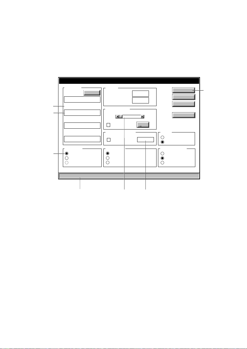
The SETUP screen
The simplest way to use SETUP is with a mouse, just
move the cursor to the option you want to select and click
with the left mouse button. The illustration below identifies
the elements that make up the SETUP screen.
XEN-LS II Setup
Memory
Total
Extended
Power on sound
Low
Enable
Power-on password
Enable
Monitor type
VGA
HiVision 14"
Multi-sync [14/17]
4096KB
3072KB
Test
High
Save
Cancel
Default
Advanced...
Startup
Graphics
Text
Ethernet interface
UTP [10BASE-T]
Thin [10BASE-2]
Thick [10BASE-5]
Option group
Text
Option button
Disk types
Hard 1
Quantum LPS120AT
Hard 2
Quantum LPS120AT
Floppy 1
3.5in 1.44M
Floppy 2
NONE
Boot device
CMOS Checksum OK
Change...
Local
Ethernet RPL
On-board other
Button
Message bar
Scroll Bar
Text Box
Option group
These are used to collect a number of related, or exclusive,
options under a common heading.
Check box
Check boxes are used where any number of the options in
the group may be selected. Select or de-select a check
box by pointing and clicking in the box with the mouse.
4

Option button
These are used for exclusive options. Beside each option
is a circle, only one circle is highlighted at any given time. If
you point and click on an option the highlight will transfer to
it.
Scroll bar
Scroll bars behave like slide controls. They are adjusted by
pointing and clicking on the arrows at each end of the bar.
Text box
These are provided when the user has to enter text. Point
and click in the text box, then enter the text required and
press
ENTER.
Text
The SETUP utility displays some information about your
system that is detected automatically and cannot be
altered. For example, the amount of memory installed in the
system is detected and displayed, for information only.
Buttons
Buttons carry out the action indicated by the text on the
button.
Message line
A message line at the bottom of the screen contains
information about SETUP.
Greyed out options
Where an option is greyed out it indicates that it cannot
currently be selected, or used. There could be a variety of
reasons for this, for example: the computer may not
support the option, or an associated option may have to be
enabled in order for the greyed out option to be valid.
5

Controlling SETUP using the keyboard
If you are unable to use a mouse, you can use the
keyboard to move around and select the SETUP options.
TAB Moves you round the option groups, and
buttons. An alternative method is to hold
down the
ALT key and press the letter
which corresponds to the one underlined
in the title of the group.
ARROW KEYS Once you are in an option group, use the
arrow keys to move through the options.
The system will highlight an entry to show
which option is currently selected.
SPACE BAR Press the space bar to set the highlighted
option.
ENTER Confirms buttons.
When the changes in a screen are complete are complete,
select the
changes, select the
SAVE button and press ENTER. To abandon your
CANCEL button and press ENTER.
System Autoconfiguration
If the system configuration has changed since the last time
the computer was booted, SETUP will be invoked
automatically.
6

Opening screen
Disk Types
Hard disk
The XEN-LS II supports a maximum of two IDE hard disk
drive(s). The type of drive fitted is displayed in these two
text boxes.
Floppy disk
The XEN-LS II can be fitted with one or two floppy drives.
These text boxes are used to display the type of drive
fitted.
There is no need to change the floppy drive type unless
you are adding a drive.
Change
The Change button accesses a screen which allows you
to select the type of each floppy drive, and provides for the
possible inclusion of user-defined hard disk drives.
Change disk type
The
later in this section.
screen is described in more detail
Boot device
The boot device option group allows you to select where
you want the XEN-LS II to look for an operating system
when it is switched on or rebooted. The group contains
three option buttons, these choose between booting from a
hard or floppy disk in the computer, and remotely across
the on-board Ethernet interface using different types of
remote boot.
If you make an inappropriate selection it may result in the
computer failing to find an operating system and being
unable to boot.
Before selecting a remote boot option check with your
network administrator.
7

Local
This should be selected if the computer is to boot from an
internal hard disk or floppy drive.
It should be noted that when one of the remote boot schemes
described below is enabled it is not possible to boot the
computer from a local device. If you wish a XEN-LS II, that
normally boots remotely using the on-board Ethernet
interface, to boot from a local device, you must first use
SETUP to select Local in the boot device option group.
Note
This option should be selected if you want the computer to
boot remotely from a server using a network interface on
an expansion card.
Ethernet
If the computer is connected to an Ethernet network using
the on-board Ethernet interface, and it is to boot remotely
from a server using the RPL (Remote Program Load)
scheme, enable this option.
Other
This option is provided for possible future implementation of
other remote boot methods for the on-board Ethernet
interface. It is currently greyed out.
Memory
The memory text box displays a count of the amount of
memory installed in the system. The contents of the text
box cannot be edited and is displayed for information only.
Separate counts of total and extended memory are
displayed.
Power-on sound
When this option is enabled the XEN-LS II audio
subsystem provides an audible indication that the system
has been switched on.
8

Volume
The volume control adjusts the output level of the PowerOn Sound. Use it to adjust the volume to suit the
computer’s location.
Test
Use the Test button to preview the Power-On Sound to
ensure that you have set it to a suitable level.
Set Power-on Password
The XEN-LS II supports a power-on password. If enabled this
password must be entered every time the system is powered
up or rebooted. If you have Apricot LOC Technology enabled
the power on password cannot be used.
When the power-on password is enabled the text box can
be selected and a password entered. The password has a
minimum length of 1 character and a maximum length of 7
characters.
Monitor type
There are three option buttons in this group: VGA, HiVision
14" and Multi-sync [14/17]. The three options alter the
timings of video signals provided by the XEN-LS II video
connector to suit a variety of different types of monitor.
It is important to ensure that you have made the correct
selection.
VGA
If you have a standard VGA monitor such as the Apricot
14" VGA Colour, or Apricot 14" VGA Paper-White you must
choose this option.
Higher resolution monitors will display standard VGA video
modes correctly if you select this option. However, if you
try to use higher resolution outputs, it is unlikely that they
will display correctly. For monitors that are capable of
displaying resolutions higher than 640x480 you should
choose one of the other selections.
9

HiVision 14"
This option must be selected only if you are using the
Apricot HiVision 14" monitor.
The HiVision 14" monitor is a dual synchronous monitor
capable of displaying 640x480 and 1024x768 video
outputs, it is also known as the Apricot High Resolution 14"
VGA monitor.
Multi-sync [14/17]
Select this mode if you are using an Apricot HiVision Low
Emission 14" or 17" monitor.
This option selects VESA compliant timings. Any multisync monitor which is compliant with the VESA timings will
work with this setting.
Note
This setting must not be chosen for the Apricot HiVision
14".
Video modes
The XEN-LS II motherboard video adapter can generate a
wide variety of video outputs. In addition to standard VGA
modes it supports seven enhanced modes as shown
below.
10
Resolution Colours Horizontal Vertical Mode Note
frequency frequency
640x480 256 31.5/37.9kHz 60/72Hz 2E 1, 3
640x480 65536 31.5/37.9kHz 60/72Hz 7A 1, 3
800x600 16 48.1kHz 72Hz 64, 6A 2
800x600 256 48.1kHz 72Hz 30 2
800x600 65536 35.2kHz 56Hz 7B 2
1024x768 1 6 48.3kHz 60Hz 37 2, 3
1024x768 256 48.3kHz 60Hz 38 2, 3

Notes
1. These modes are displayable on a standard VGA
monitor. The higher frequencies are selected when
multi-sync [14/17] is selected in SETUP. Higher
frequency variants use VESA compliant timings and
are displayable on the Apricot HiVision Low
Emission 14" and 17" monitors, and other VESA
timing compliant multi-sync monitors.
2. These modes use VESA compliant timings and are
displayable on the Apricot HiVision Low Emission
14" and 17" monitors, and other VESA timing
compliant multi-sync monitors.
3. These modes are displayable on an Apricot HiVision
14" monitor. When using a HiVision 14" monitor
(also known as a High Resolution 14" VGA monitor)
you must select the HiVision 14" option in the
monitor type option group.
In addition to the enhanced modes listed in the table above,
VGA mode 12 (640x480x16 colour) also uses the higher
vertical frequency when multi-sync [14/17] is selected.
In order to display these enhanced modes correctly you
must ensure that the correct monitor type is selected.
Selecting the wrong monitor type could result in nothing
being displayed.
To take advantage of these modes suitable display drivers
must be used. A set of drivers for popular applications is
supplied with your computer. Installation instructions are
provided in help files supplied with the drivers.
Startup
Graphics
When graphics is selected the initial boot screen is
displayed in graphical format.
Text
When text is selected a text based boot screen is used.
11

Ethernet interface
These three option buttons are used to select the type of
Ethernet the XEN-LS II is connected to.
Warning
You must select the correct interface. If you choose the
wrong one you will not be able to use the network
connection.
Advanced
This button activates a screen of advanced options. Many
of the options affect the operation of the motherboard, and
should only be changed by the technically competent user.
The operation of the
later in this section.
Advanced
screen is described in detail
12
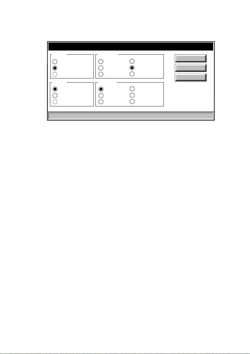
Change disk types
Change disk types
Hard 1
None
Autodetect
User-defined
Hard 2
None
Autodetect
User-defined
Hard 1 and 2
For Apricot supplied drives always use Autodetect. This
will ensure that the system uses the correct parameters for
the drive.
The user-defined entry is for possible future enhancement
to allow non-standard drives to be used.
Floppy 1 and 2
Floppy 1
None
5.25" 360K
5.25" 1.2M
Floppy 2
None
5.25" 360K
5.25" 1.2M
3.5" 720K
3.5" 1.44M
3.5" 2.88M
3.5" 720K
3.5" 1.44M
3.5" 2.88M
Save
Cancel
Default
These two option groups allow to select which type of
floppy drive is installed.
Floppy 1 will always be a 3.5" device, 1.44M being the
standard fitment.
Floppy 2, if fitted, will usually be a 5.25" 1.2M device.
The other options are included for compatibility reasons,
and for possible future enhancement.
13
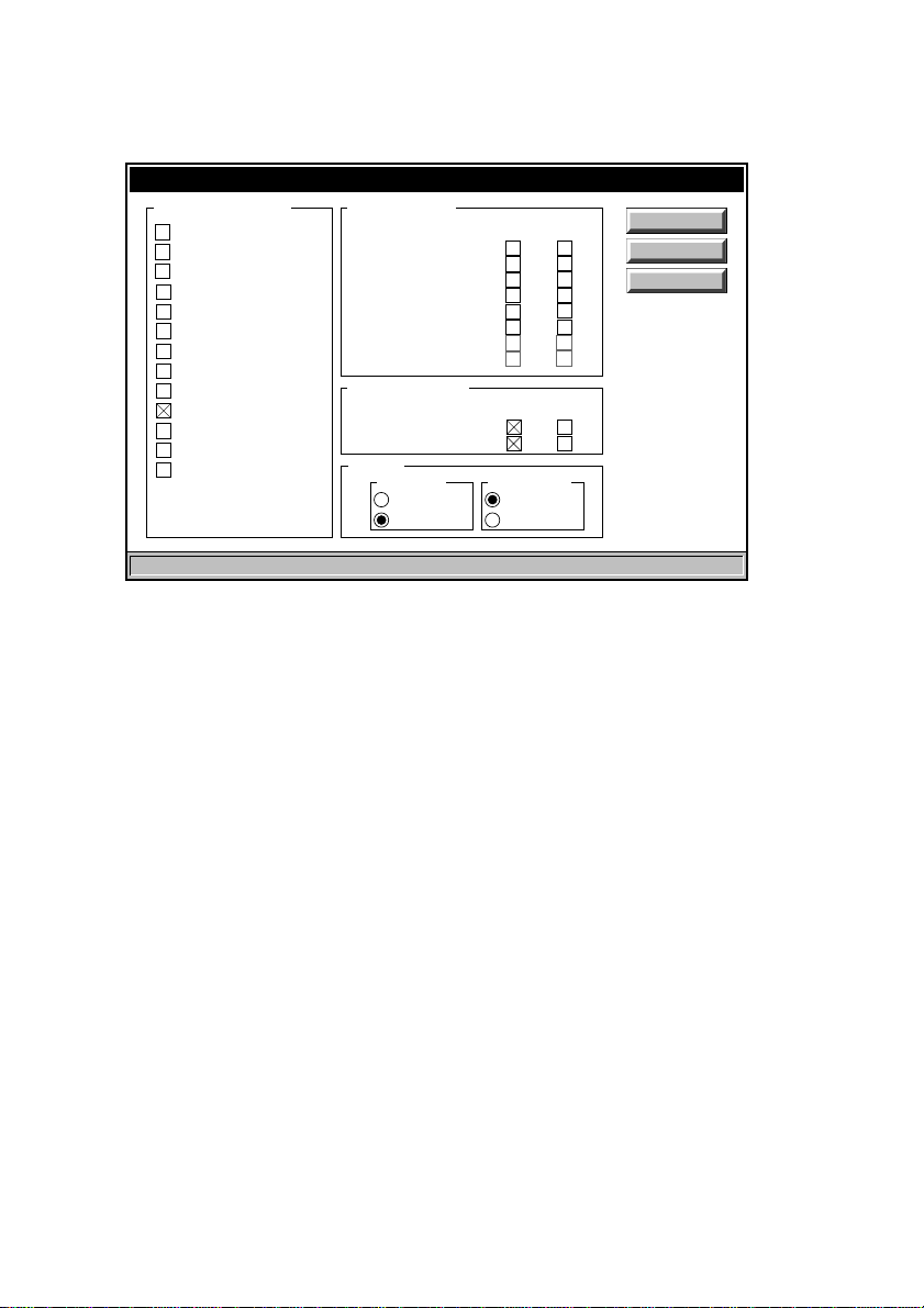
Advanced options
Advanced options
Disable motherboard
Serial port 1
Serial port 2
Parallel port
Digital audio system
Hard disk controller
Floppy disk controller
CD-ROM interface
Ethernet coprocessor
BIOS copy at 16MB
Memory hole at 16MB
i486 cache
External cache
Expansion slots
Disable motherboard
These check boxes allow you to selectively disable
motherboard features. You should only disable any of these
functions if you are sure it is appropriate.
Adapter Memory
DC000-DFFFF
D8000-DBFFF
D4000-D7FFF
D0000-D3FFF
CC000-CFFFF
C8000-CBFFF
C4000-C7FFF
C0000-C3FFF
Motherboard BIOS
System [E0000-FFFFF]
Video [C0000-C7FFF]
ISA bus
Bus speed
Slow
Fast
Shadow Wrt.Protect
Shadow Wrt.Protect
Save
Cancel
Default
I/O decoding
10 bit
16 bit
14
Serial port 1, 2, Parallel port
Checking a box disables the port associated with that box.
You should only disable a port if you are sure that you do
not want to use it.
Disabling a port in SETUP disables the relevant
motherboard hardware and frees the interrupt associated
with the port. Information on interrupts and their usage is
given in Appendix A at the rear of this guide.
Digital audio system
Checking this box disables the Apricot audio feature. You
should only disable the audio system if you are not using it.

Note
This check box disables the Apricot audio hardware, it has
no affect on the standard ISA sound capabilities.
Disabling the Apricot audio system frees the interrupt, and
the DMA channels associated with the audio system.
Information on interrupts, DMA channels, and their usage is
given in Appendix A at the rear of this guide.
Hard disk controller
Checking this box disables the motherboard hard disk drive
interface. You should only disable the interface in a system
without a hard disk drive.
Disabling the interface in SETUP disables the relevant
motherboard hardware and frees the interrupt associated
with the it. Information on interrupts and their usage is given
in Appendix A at the rear of this guide.
Floppy disk controller
Checking this box disables the motherboard floppy drive
interface. Since all XEN-LS II systems are supplied fitted
with at least one diskette drive you should not normally
disable the interface.
Disabling the floppy drive interface in SETUP disables the
relevant motherboard hardware and frees the interrupt and
the DMA channel associated with it. Information on
interrupts, DMA channels, and their usage is given in
Appendix A at the rear of this guide.
CD-ROM interface
Checking this box disables the motherboard CD-ROM
interface. You should only disable the interface in a system
without a CD-ROM drive.
Disabling the CD-ROM interface in SETUP disables the
relevant motherboard hardware and frees the interrupt and
the DMA channel associated with it. Information on
interrupts, DMA channels, and their usage is given in
Appendix A at the rear of this guide.
15

Ethernet coprocessor
Checking this box disables the Ethernet coprocessor. You
should only disable the Ethernet coprocessor if you are not
using it.
Disabling the Ethernet coprocessor in SETUP disables the
motherboard hardware and frees the interrupt associated
with the coprocessor. Information on interrupts and their
usage is given in Appendix A at the rear of this guide.
BIOS copy at 16MB
In an ISA compatible system a copy of the system BIOS
appears at 16 Mbytes. Checking this box removes that
copy of the system BIOS from the memory map.
In systems fitted with up to 16 Mbytes of RAM the box can
be either checked, or unchecked, it is unlikely to have a
significant effect.
In systems fitted with more than 16 Mbytes of RAM the box
must be checked.
Memory hole at 16MB
This option is used to enable or disable a hole in
motherboard memory. The hole, when enabled, appears
from 16M-128k to 16M.
16
This option should normally be disabled, and there is no
hole in the memory map. The hole should only be enabled
when the system RAM capacity is 16Mbytes or greater,
and you have an expansion card which uses memory
mapped I/O.
i486 cache
Checking this box disables the cache memory inside the
i486 processor. There should normally be no reason to
disable the processor cache, it will result in a performance
decrease.

Some old software which is speed sensitive may not work
properly with the cache enabled. This problem is
uncommon, and this option is provided as a safety net.
External cache
Checking this box disables the external cache, the cache
outside the i486. There should normally be no reason to
disable this cache, it will result in a performance decrease.
Some old software which is speed sensitive may not work
properly with the cache enabled. This problem is
uncommon, and this option is provided as a safety net.
If your XEN-LS II is not equipped with the external cache
this option will be greyed out.
Expansion slots
Checking this box disables all three expansion slots.
This option would not normally be used, however under
certain circumstances it may be useful. For example, if you
install an expansion card and the computer fails to boot
when you power it up. You may be able to use this SETUP
option to disable the expansion slots, and get the computer
to boot.
Motherboard BIOS
The system and VGA BIOS on the motherboard is stored
in ROM which has long access times. Enabling BIOS
shadowing enhances the performance of the system by
copying the contents of the BIOS ROM into RAM.
By copying the BIOS into RAM the system takes
advantage of the shorter access times of RAM. An
additional benefit is that shadowed ROM spaces are
cached gaining a further performance advantage.
Shadow
Checking this box enables BIOS shadowing for the
associated address range.
17

Write protect
Checking this box enables write protection for the
associated shadowed address range.
The normal state for this option will be disabled, the box not
checked. It is extremely rare for software to attempt to write
to ROM address ranges, and leaving write protection
disabled results in a performance advantage.
If you enable write protection then shadowed ROM spaces
can never be overwritten, this is safer, but results in lower
performance.
Adapter BIOS
BIOS on the expansion cards is stored in ROM which has
long access times. Enabling BIOS shadowing enhances
performance by copying the contents of the ROM into
RAM.
By copying the BIOS into RAM the system takes
advantage of the shorter access times of RAM. An
additional benefit is that shadowed ROM spaces are
cached gaining a further performance advantage.
Shadow
18
Checking this box enables BIOS shadowing for the
associated address range.
Warning
Shadowing is only appropriate for adapter ROM. It must
never be enabled for adapter card RAM in these regions.
Write protect
Checking this box enables write protection for the
associated shadowed address range.
The normal state for this option will be disabled, the box not
checked. It is extremely rare for software to attempt to write
to ROM address ranges, and leaving write protection
disabled results in a performance advantage.

If you enable write protection then shadowed ROM spaces
can never be overwritten, this is safer, but results in lower
performance.
ISA bus
Bus speed
These two options, in conjunction with a switch on the
motherboard, allow the speed of the ISA bus to be varied.
When this option is set to Fast, and the switch on the
motherboard is set to 8MHz the bus is fully compatible with
the ISA specification.
If this option is set to Slow and the switch on the
motherboard is set to 8MHz the bus is slightly slower than
the ISA specification.
If this option is set to Slow and the switch on the
motherboard is set to 10MHz the bus is slightly faster than
the ISA specification.
If this option is set to Fast and the switch on the
motherboard is set to 10MHz the bus is significantly faster
than the ISA specification.
I/O decoding
These two option buttons allow you to choose whether 16
or 10 address bits are decoded for I/O cycles to the ISA
bus.
16 bit decoding allows access to the full 64K I/O space on
the ISA bus.
10 bit decoding is slightly quicker, but restricts I/O
accesses on the ISA bus to the bottom 1K, from 0h to
399h.
19

Exiting SETUP
Use either the SAVE or CANCEL button to close the
or
disk type
The
SAVE button will implement any changes that you have
Advanced
made in a screen. The
windows.
CANCEL button exits that screen
without implementing any changes.
Selecting Save or Cancel from the opening screen will exit
SETUP. If any changes have been made the computer will
reboot when you exit SETUP.
Change
20

Installing add-ons
Introduction
This section contains instructions on installing add-ons and
upgrades in the XEN-LS II. The areas covered include:
* expansion cards
* additional memory
* processor upgrades
* additional drives
This document should be your only source of information
when installing any of these.
Read this document before purchasing an add-on or
upgrade. If, having read the relevant instructions, you are
not confident about installing the upgrade, you may wish to
have your supplier or service organisation install it for you.
Before you start installing the upgrade you should be
thoroughly familiar with all the relevant instructions in this
guide and any appropriate sections of your
Handbook
.
Owner’s
Warning
Never carry out any work on the equipment with power
applied. Always switch off at the mains and remove the
power lead from the equipment before starting work.
Appendices at the rear of this section provide information
on expansion card configuration and a pinout of the
motherboard video feature connector.
The only tool required to complete the installation of any of
the upgrades is a small cross-head screwdriver.
21

Inside the system unit
The illustration below identifies the major components
inside the XEN-LS II system unit that are affected by the
installation instructions later in this section.
PROCESSOR
UPGRADE SOCKET
BLANKING
PLATES
EXPANSION
CARD
CONNECTORS
POWER
SUPPLY
3.5"
DRIVE BAY
22
CARD
GUIDES
BRACE
SIMM
SOCKETS
5.25"
DRIVE BAY

Expansion cards
Installation
The XEN-LS II provides three slots for the installation of
expansion cards. These slots are ISA (also known as AT)
compatible.
Installation of an expansion card in the XEN-LS II is a
simple process requiring the removal of only the system
unit cover and a blanking plate. The following instructions
and illustrations describe how to install a card in a simple
step-by-step sequence.
1. Power the system down.
2. Take suitable anti-static precautions and remove the
system unit cover.
If you are unfamiliar with Apricot’s recommended
anti-static precautions and/or the process of
removing the system unit cover refer to either; the
appendices at the rear of this guide, or your
Handbook
.
3. With the system unit cover removed, the space for
expansion cards will be visible. It is on the left side
of the system unit behind the activity indicators and
the volume control. Use the illustration below to help
you identify this area.
Owner’s
EXPANSION CARD
CONNECTORS
BLANKING PLATES
CARD GUIDES
23

At the rear of the area are three metal blanking plates,
one for each expansion card slot. These plates cover
slots in the rear of the system unit which will be used
by expansion cards.
At the front of the area are three guides. These ensure
that the front edge of any full length card is secured.
4. The blanking plates described above are each secured
by a screw. Using the following guidelines decide which
of the available slots you wish to install the card in, then
remove the appropriate blanking plate.
In general it is easiest to start with the lowest slot and
work towards the top, but there a couple of
exceptions. If you are installing a card which uses the
video feature connector on the motherboard then it is
best to install the card in the lowest slot. If you are
installing a drive controller card that you want to
connect to a drive in the 5.25" drive bay, then it is
easiest to install it in the top slot.
Warning
The video feature connector on the XEN-LS II
motherboard uses a non-standard pinout. In order to use
the connector you will need to make up a special cable.
A pinout of the XEN-LS II video feature connector is
given in the Appendix B at the rear of this guide.
To remove the blanking plate, first unscrew the
securing screw , then slide the plate out of its slot. K eep
the screw, you will use it later to secure the card.
5. You are now ready to install the card. However,
before you do so you must first ensure that the card is
correctly configured for your system.
Information on configuring cards for use in the
XEN-LS II is given in the
appendix at the rear of this guide. Use this information in
conjunction with the documentation supplied with your
card to configure the card so that it will not clash with
any of the features on the XEN-LS II motherboard, or
any other expansion cards already installed.
A table for noting the configuration of cards is included
in Appendix A.
Configuring expansion cards
24

6. Position the expansion card alongside the slot in
which you wish to install it. Align the rear of the card
with the slot in the rear of the system unit, and, if the
card is full length, the front of the card with the card
guide.
Note
If the card uses the video feature connector on the
motherboard, you must plug the video feature cable
into the motherboard socket before you install the
card.
7. Slide the card into the slot ensuring that the card
edge connector engages correctly with the
expansion card connector.
8. Carefully push the card fully home. Do not apply
excessive pressure.
9. Secure the card by replacing the screw that you
removed in step 4.
10. Connect any signal cables to the card.
11. Replace the system unit cover.
25

Memory
Configurations
The XEN-LS II motherboard is fitted with 4 Mbytes of onboard memory, and sockets for two SIMMs (Single In-line
Memory Modules). Each socket can be empty, or fitted with
a SIMM of 4, 8, 16 or 32Mbytes capacity.
The sockets support standard 36-bit, 70ns SIMMs of 4, 8
and 16 Mbytes. The 32 Mbyte SIMM must be obtained from
Apricot, standard 32 Mbyte SIMMs will not work in the
XEN-LS II. The table below identifies the possible memory
capacities using the various SIMM combinations.
MM1 MM2 Upgrade Motherboard Available
capacity capacity capacity memory memory
---4 4
4-44 8
8-84 12
16 - 16 4 20
32 - 32 4 36
4484 12
48124 16
416204 24
88164 20
816244 28
16 16 32 4 36
32 4 36 4 40
32 8 40 4 44
32 16 48 4 52
32 32 64 4 64
Note
When a 32Mbyte SIMM is installed in MM2 the motherboard
memory is disabled.
26
It should be noted that, for all combinations the SIMM in
MM1 can be swapped with that in MM2. In every case the
computer will operate correctly when it is powered up, and
in most cases there will be no difference in the operation of
the computer.

There are only two exceptions to this. In the two situations
given below, although the computer will operate if the
SIMMs are swapped it is preferable if the SIMMS are
installed as described.
* If you are installing a 4Mbyte SIMM it should always
go in MM1, unless there is a 4 or 32Mbyte SIMM in
the socket already.
* If you are installing a 32Mbyte SIMM it should
always go in MM1 unless there is a 32Mbyte SIMM
in the socket already.
If in either of the cases above you install a 4 or 32 Mbyte in
MM2 when you power the system up you will be prompted
to swap the SIMMs.
Installation
In order to install a memory upgrade you must:
1. Power the system down.
2. Take suitable anti-static precautions and remove the
system unit cover.
If you are unfamiliar with Apricot’s recommended
anti-static precautions and/or the process of
removing the system unit cover refer to your
Owner’s Handbook
.
27

The SIMM connectors are located beneath the 5.25" drive
bay. In order to install a memory upgrade you must remove
the 5.25" drive bay.
5.25" BAY
SECURING SCREWS
3. If there is a drive fitted disconnect the power and
signal cables from the rear of the drive.
4. Remove the two screws that secure the drive bay
and slide the bay backwards.
28
5. Lift the bay out of the system unit and put it down on
a safe flat surface.

Removing a SIMM
If you wish to install an upgrade in a SIMM socket which is
already occupied you must first remove the existing SIMM.
1. Lever the metal clips on each side of the socket
gently away from the SIMM using your forefingers.
2. Place your thumbs on the top edge of the SIMM and
move it gently towards the vertical.
3. When the SIMM has rotated through 20°, taking care
to avoid touching any of the components on the
SIMM, grip the top corners of the SIMM between
thumb and first finger and carefully pull the SIMM out
of the socket.
29

Inserting a SIMM
From the table of possible SIMM combinations decide
which SIMM capacity will be installed in the socket. Then
install the SIMM.
To fit a SIMM:
1. The SIMM will only install in one orientation. There is
a cutout at one end of the SIMM next to the
connector strip.
Hold the SIMM with the cutout on the right and metal
connector strip nearest the motherboard.
2. Position the SIMM above the socket with the SIMM
tilted slightly towards the front of the system unit.
30
3. Lower the SIMM into the socket, and ensure that the
SIMM is properly located in the connector.

4. Pushing gently on the top corners rotate the SIMM
towards the horizontal until it clips into place. Do not
use excessive force.
If the SIMM will not rotate easily remove it and start
again.
5. If the SIMM is properly located the SIMM should
remain in position held by the securing clips, and
with a small plastic lug through the holes on either
side of the SIMM.
If you want to install a second SIMM repeat the process
above. Once you have completed installation you can
replace the 5.25" drive bay and reassemble the system.
1. Replace the 5.25" bay in the system unit.
2. Slide the bay forwards until the two holes in the bay
line up with those in the hard drive assembly and the
system unit brace.
3. Replace the two screws which secure the 5.25"
drive bay.
4. If there is a drive in the bay reconnect its power and
signal cables.
5. Replace the system unit cover.
The next time you power the system up the SETUP utility
will be invoked automatically.
31

Processor upgrades
The XEN-LS II motherboard is fitted with a processor
socket that supports any Intel486SX, Intel487SX,
Intel486DX, Intel486DX2 or OverDrive processor with a
maximum external clock speed of 33MHz.
Any other Intel processor using the same pinout as one of
these processors could also be installed, subject to the
same 33MHz maximum external clock speed restriction.
The table below lists the possible upgrades for each
processor type and speed.
Current Upgrade
Processor Speed Processor Speed
Intel486SX 25 Intel487SX 25
Intel487SX 33
OverDrive 25
OverDrive 33
Intel486SX 33 Intel487SX 33
OverDrive 25
OverDrive 33
Intel486DX 33 OverDrive 25
OverDrive 33
Note
This table lists the processors supported by the
motherboard. There is no guarantee that any particular
upgrade processor will be available at any given time.
Depending on the processor type fitted in your system unit
the processor socket may already be occupied. Before
installing the upgrade processor you must first check
whether the processor socket is occupied, and if it is,
remove the existing processor. Instructions on locating the
socket and removing a processor are given below.
1. Power the system down.
2. Take suitable anti-static precautions and remove the
system unit cover.
If you are unfamiliar with Apricot’s recommended
anti-static precautions and/or the process of
removing the system unit cover refer to your
Owner’s Handbook
.
32

3. Identify the processor upgrade socket.
UNOCCUPIED SOCKET
OCCUPIED SOCKET
int l
e
D
OVER
V
R
I
E
If the socket is not occupied it will look like the close
up on the left and you can continue to the installation
instructions.
If the socket is occupied it will look like the close up
on the right, and you will have to remove it before
you can install your upgrade processor.
4. Your upgrade processor is supplied with an
extraction tool which resembles a miniature garden
rake.
33

5. Carefully insert the prongs of the extractor between
the bottom of the processor and its socket. You may
need to twist the extractor gently from side to side to
work the prongs into place.
Be careful to ensure that the prongs do not go
between the motherboard and the socket.
6. Ease the processor up slightly by pushing inwards
on the extractor’s handle.
Warning
Do not push hard on the handle. The processor
must be removed gradually and evenly by working
the tool under each edge in turn. Attempting to lift
one edge of the processor too far will damage the
processor, or the socket, or both.
34
7. Remove the extractor and repeat the process on
each edge of the processor, gradually easing the
processor out of its socket. If necessary work your
way round the processor two or three times.
8. Once the processor is free of its socket lift it out of
the system unit and place it on the anti-static foam
provided with the upgrade processor.

Installation
You should now have identified the upgrade socket, and
ensured that it does not have a processor in it. You are
ready to install your new upgrade processor.
1. The upgrade processor and socket are keyed to
ensure that the processor can only be installed in
one orientation.
The inside of one corner of the socket has a key
hole, the outside of the same corner is missing three
holes. The processor has a positioning guide in the
form of a small dot of paint. Use the following
illustration to help identify these features.
int l
e
D
OVER
V
R
I
E
POSITIONING
GUIDE
KEYED
CORNER
35

2. Carefully position the upgrade processor above the
socket with the positioning guide on the processor
over the keyed corner of the socket.
If the upgrade processor does not occupy all four
rows of holes it should be positioned centrally as
shown below.
PROCESSOR
IN CENTRE
int l
e
D
UNOCCUPIED
HOLES ON
EACH SIDE
OVER
V
R
I
E
Warning
If the processor is misaligned it will not go into the
socket, and any attempt to force it will damage the
processor, or the socket, or both.
3. Gently insert the upgrade processor making sure
that it is correctly aligned with the socket and that
you do not bend or otherwise damage the pins.
36
4. Once you are certain that all the pins on the
processor are in the holes in the socket apply firm
even pressure to the top of the processor to seat the
pins in the socket.
5. With the upgrade processor installed you must now
ensure that the upgrade socket, and motherboard
clock speed are correctly configured for your new
processor.
Configuring the motherboard
overleaf describes how
to ensure that when you reassemble your system
the new processor will work.

Configuring the motherboard
The XEN-LS II motherboard supports a range of processor
speeds and the upgrade socket supports a range of
processor types. The motherboard clock speed and the
upgrade socket are configured using four switches in a set
of six by the socket.
It is vital that both the system clock speed, and the upgrade
socket configuration are set correctly. Follow the
instructions below to check the settings and adjust them as
necessary.
1. Use the following illustration to identify the switches.
6
5
4
3
int l
e
D
OVER
V
R
I
12
ON
E
SWITCH PACK
The switches numbered 2 and 3 are used to select
the system clock speed. Switches 4 and 5 are used
to configure the upgrade socket.
Warning
Under no circumstances should switches 1 and 6 of
the switch pack be moved. It is essential that both
switch 1 and switch 6 are in the on position.
37

2. From the table below, and the label on your upgrade
processor or its packaging, decide which processor
type you have installed.
Since the Intel487SX and OverDrive upgrade
processors require the same configuration you will
normally set switches 4 and 5 to the Off/Off position.
The other selections are for processors normally
installed during manufacture.
Switch Processor
45
off off Intel487SX/OverDrive Upgrade
off on Intel486DX/Intel486DX2/
OverDrive Replacement
on off Intel486SX
on o n not used
3. Having decided which selection you require check
the positions of switches 4 and 5, and if necessary
move them to the appropriate position.
The easiest way to move the switches is with the
point of a pencil or small screwdriver.
4. From the table below, and the label on your upgrade
processor, or its packaging decide which system
clock speed you need to select.
38
Switch Clock speed
2 3 (MHz)
on on 16
on off 20
off on 25
off off 3 3
You will almost certainly want to set the clock speed
to either 25 or 33MHz.
If you have installed an Intel487SX you must set the
system clock speed to match the speed of the
coprocessor.

If you have installed an OverDrive processor you
should set the system clock speed to match the
external interface speed of the processor.
OverDrive processors use Intel’s clock doubling
technology and the processor runs at twice the
speed of its interface to the motherboard.
The labelling on the OverDrive processor or its
packaging should make it clear what its external
interface speed is.
5. Having decided which selection you require check
the positions of switches 2 and 3, and if necessary
move them to the appropriate position.
The easiest way to move the switches is with the
point of a pencil, or a small screwdriver.
6. You should by now have: identified the upgrade
socket, and if necessary removed the processor
fitted in it, installed the new processor, configured
the upgrade socket, and set the system clock
speed. If you are uncertain about having completed
any of these steps, go back to the beginning and
check the steps you carried out against the
installation instructions.
7. Once you are satisfied that you have installed the
upgrade and configured the system correctly,
reassemble the system.
39

5.25" drives
The 5.25" drive tray in the XEN-LS II system unit can
contain any standard size half height 5.25" device. Apricot
supplies a range of tape and CD-ROM drives, and a 5.25"
floppy drive, for this bay.
The following instructions describe the installation of a drive
in the bay. The
Generic
describe the physical installation of a drive.
Instructions specific to each drive type are given after the
generic instructions.
Generic
1. Power the system down.
2. Take suitable anti-static precautions and remove the
system unit cover.
If you are unfamiliar with Apricot’s recommended
anti-static precautions and/or the process of
removing the system unit cover refer to your
Owner’s Handbook
instructions apply to all drives, and
.
5.25" BAY
40
SECURING SCREWS
3. Remove the two screws that secure the drive bay
and slide the bay backwards.

4. Lift the bay out of the system unit.
5. The front of the bay is fitted with a blanking plate.
Turn the bay over and remove the two screws that
secure the blanking plate. The blanking plate is no
longer required, but you may wish to store it
somewhere safe in case you wish to remove the
drive later.
SECURING SCREWS
BLANKING PLATE
6. Remove the drive from its packaging. With the drive
there should be four screws and a signal cable.
Some drives may be supplied with additional items.
7. If necessary configure the drive. Drives supplied by
Apricot will be correctly configured for installation in
a XEN-LS II.
For information on how Apricot-supplied drives are
configured see the drive specific information
following these installation instructions.
8. Identify the top and bottom of the drive.
9. Rest the drive, top down, on a suitable anti-static
surface.
41

10. With the drive bay upside-down place it over the
drive. The front of the drive must be at the end
where the blanking plate was fitted.
SECURING
SCREW
HOLES
COMPACT
42

11. Line up the holes in the underside of the drive with
those in the base of the drive bay.
SECURING SCREWS
COMPACT
12. Insert the four drive securing screws, and tighten
them until they are finger tight.
13. Gently tighten the four screws.
14. Turn the drive bay over and replace it in the system
unit.
15. Slide the bay forwards until the two holes in the bay
line up with those in the hard drive assembly and the
system unit brace.
16. Replace the two screws that secure the drive bay.
43

17. Behind the 5.25" drive bay is an unused power cable
from the power supply. Connect this power cable to
the power connector on the drive.
5.25" DRIVE
POWER CABLE
int l
e
D
OVER
V
R
I
E
44
18. The drive has now been installed and connected to
a power cable. You must now connect it to a signal
cable. Instructions on connecting each of the types
of drive to a signal cable is given under the
appropriate heading overleaf.

5.25" floppy or Irwin FTD
Cabling
The 5.25" floppy and Irwin FTD drives supplied by Apricot
come complete with a suitable signal cable. The signal
cable must be connected between the signal connector on
the rear of the drive, and the socket marked PL38 on the
motherboard.
Use the label on the inside of the system unit cover to
identify PL38.
Warning
Check the label on the inside of the system unit cover to
make sure you are using the correct connector. Failure to
do so may damage the drive or the system board.
Configuration
The only configuration on these drives is via the drive
select jumpers at the rear of the drive. The jumpers should
be set to drive select 1 (DS1).
SLCD CD-ROM
Cabling
The Apricot SLCD CD-ROM drive is supplied with two
signal cables. The wide data cable must be connected
between the rear of the SLCD CD-ROM drive and PL36 on
the motherboard. The narrow audio cable must be
connected between the drive and PL4 on the motherboard.
Use the label on the inside of the system unit cover to
identify PL36 and PL4.
Warning
Check the label on the inside of the system unit cover to
make sure you are using the correct connectors. Failure to
do so may damage the drive or the system board.
Note
If there is an expansion card installed in the bottom slot you
will have to remove it in order to access PL4.
45

Configuration
There are no configuration options on the SLCD CD-ROM
drives. DOS drivers for the SLCD CD-ROM drive are
described in help files on a diskette supplied with the drive.
SCSI drives
Cabling
Apricot upgrade kits are supplied with a suitable signal
cable. The cable should be connected between the SCSI
card and the rear of the drive.
The connector at the drive end should be fitted with a
termination assembly. The following illustration shows the
routing of the cable.
SCSI CABLE
int l
e
TM
DX
486
i
46

Configuration
Each SCSI drive is assigned an identity on the SCSI bus,
these are known as SCSI IDs. All Apricot SCSI drives for
XEN-LS II are supplied configured with SCSI ID 2.
All Apricot SCSI drives are supplied without termination.
SCSI bus termination is provided by the SCSI card and the
termination assembly in the last connector at the drive end
of the cable.
47

3.5" hard disk drive
The XEN-LS II supports one 1.6" high or two 1" high, 3.5"
hard disk drives.
Preparation
To install a hard disk drive you must first remove the 3.5"
drive bay:
1. Power the system down.
2. If there is a diskette in the 3.5" floppy drive, remove it.
3. Take suitable anti-static precautions and remove the
system unit cover.
If you are unfamiliar with Apricot’s recommended antistatic precautions and/or the process of removing the
system unit cover refer to your
Owner’s Handbook
In order to remove the 3.5" drive bay you must first remove
the 5.25" drive bay.
5.25" BAY
.
48
SECURING SCREWS
4. If there is a drive fitted in the 5.25" bay disconnect
the power and signal cables from the rear of the
drive.

5. Remove the two screws that secure the 5.25" drive
bay and slide the bay backwards.
6. Lift the 5.25" bay out of the system unit and put it
down on a safe flat surface.
7. Disconnect the cable from the rear of the 3.5" floppy
drive.
8. If a 3.5" hard disk is fitted remove the signal and
power cables from the rear of the drive.
9. The 3.5" drive bay is secured by two screws and
two lugs in the system unit base. Identify the screws
and lugs from the following illustration.
int l
e
TM
DX
486
i
SECURING
SCREWS
10. Remove the two securing screws shown in the
illustration above.
11. Slide the 3.5" drive bay backwards and lift it out of
the system unit.
49

Drive configuration
The XEN-LS II 3.5" drive bay supports two 1" high hard
disk drives. In order for the drive or drives to operate they
must be correctly configured.
The IDE interface supports a maximum of two drives.
These drives are known as Master and Slave. A single
drive, or the boot device in a dual drive system, must be
configured as Master. The second, non-bootable, drive in a
dual drive system must be configured as Slave.
IDE drives are normally configured using jumpers on the
drive. Configuration details may vary from drive to drive.
Apricot drives are supplied with documentation describing
how to configure the drive.
If you are uncertain about configuring the drive check with
your supplier.
50

Installing the drive
1. Having configured the drive, turn the drive bay
upside-down and rest it on a flat surface with the
front of the floppy drive towards you.
2. Slide the hard disk drive you are installing into the
bay from the front, with the drive circuit board up,
and its connectors away from you.
Warning
If there is a drive in the bay already, be careful to
ensure that the new drive does not touch it.
Warning
It is possible to damage hard disk drives when
attaching them using side mounting holes. When
installing Apricot supplied hard disk drives make
sure that you use the screws supplied with the
drive, and that all washers supplied are used.
When installing drives supplied by third parties, be
careful to ensure that securing screws do not come
into contact with drive circuit boards. If in doubt
check with your supplier.
3. Line up the screw holes on the sides of the drive
with those in the bay, insert the securing screws
supplied with the drive and tighten them until they
are finger tight.
51

Note
If you are installing a hard disk drive in a system that
previously had only a floppy drive there will be two
sets of holes available in the bay. Install the hard
drive in the position closer to the floppy drive.
4. Carefully tighten the screws.
5. Turn the bay over.
Reassembling the system
1. Replace the 3.5" drive bay in the system unit. Make
sure that the cutouts in the bay align with the lugs in
the base of the system unit.
2. Carefully slide the 3.5" drive bay forwards. The bay
is in position when the floppy drive operating button
protrudes through the front bezel and the two screw
holes in the bay line up with those in the base of the
system unit.
3. Replace the two securing screws.
4. Connect the 3.5" hard disk(s) to their signal and
power cables.
5. Reconnect the 3.5" floppy drive cable.
52
Warning
If the 3.5" floppy drive cable has been disconnected
from the system board make sure that you
reconnect it to the correct connector. Check the
label on the inside of the system unit cover.
6. Replace the 5.25" bay in the system unit.
7. Slide the bay forwards until the two holes in the bay
line up with those in the hard drive assembly and the
system unit brace.
8. Replace the two screws which secure the 5.25"
drive bay.
9. If there is a drive in the bay reconnect its power and
signal cables.
10. Replace the system unit cover.

Appendix A: Configuring expansion
cards
Many ISA expansion cards have a number of configurable
options. These options can include items such as: the
interrupt used, the DMA channel used, where any ROM on
the card will appear in the processor’s memory map and
the address of any I/O ports used to control the card.
How to select options like this varies from card to card and
will be described in documentation supplied with the card.
Remember to check any floppy disks supplied with the
card for README or Help files.
Most ISA cards use jumpers and/or switches to select their
configuration options. If this is the case then the card
should be configured before you install it. A few cards are
configured using a software utility supplied with the card,
this can only be done after the card is installed.
If you are not familiar with the concepts of interrupts, DMA
channels, memory maps and I/O ports the following text
attempts to explain what they are, and how to decide which
option to select.
For the following explanations it should be understood that
a peripheral can be either, a subsystem on the
motherboard, or an expansion card.
53

Interrupts (IRQ)
The XEN-LS II (like every other ISA compatible PC)
supports 15 hardware interrupts. These interrupts are used
to alert the processor that a peripheral (e.g. the keyboard
controller, or an expansion card) requires a particular piece
of software to be executed. This piece of software is known
interrupt service routine
as an
Each peripheral has a unique interrupt service routine that
is executed in response to the interrupt assigned to that
peripheral.
When an interrupt occurs the processor stops executing its
current task, executes the interrupt service routine, then
returns to its original task. The processor is, literally,
interrupted.
A hardware interrupt may be referred to as an IRQ. This is
because the motherboard signals used to generate the
interrupts are labelled IRQ
and 15, excluding 2.
Note
.
x
where x is a number between 0
In an ISA compatible system if you select IRQ2 on an
expansion card it uses IRQ9. This means that if an
expansion card is using IRQ2, no other card can use
IRQ9.
Some interrupts are assigned to standard functions and are
essential for the operation of the board. Examples of these
are, IRQ0 which is used to maintain the system time, and
IRQ13 which is used by the coprocessor.
54
Selecting IRQs for cards
The table below lists the interrupts available on the
motherboard and their default functions. The notes explain
whether the default function can be disabled, if so how, and
under what circumstances it is safe to do so.

Interrupts Default Notes
IRQ9 Video IRQ9 is not normally used in the XEN-LS II implementation
IRQ7 Parallel port IRQ7 is not normally used, and can be used by expansion
IRQ3 Serial port 2 Each of the serial ports, can be individually disabled using
IRQ4 Serial port 1 SETUP. When a port is disabled, the interrupt assigned to it
IRQ5 SLCD The SLCD interface can be disabled using SETUP if you do
IRQ1 0 INA The Ethernet interface can be disabled using SETUP if you
IRQ 15 Audio The audio system can be disabled using SETUP if you are
IRQ1 4 Hard disk The hard disk controller can be disabled using SETUP in a
IRQ1 Keyboard These interrupts cannot be used by an expansion card
IRQ6 Floppy disk under any circumstances.
IRQ8 Real time clock
IRQ11 Security
IRQ12 Mouse
Function
and can be used by an expansion card.
cards without affecting the operation of the parallel port. It is
possible for software to enable the parallel port’s use of
IRQ7. This is rare but could cause problems with a card
using IRQ7.
If you are not using the parallel port it can be disabled using
SETUP, freeing IRQ7 to be used by an expansion card.
is free and can be used by an expansion card. You should
only disable a port if you are certain that you will not be using
it.
interface not have an SLCD CD-ROM drive fitted. In this case IRQ5 is
(Ethernet) are not using the on-board Ethernet adapter to connect to a
controller XEN-LS II which is not equipped with a hard disk. In this
controller
available for an expansion card.
network. In this case IRQ10 is available for an expansion
card.
not using it. In this case IRQ15 is available for an expansion
card.
case IRQ14 is available for an expansion card.
Warning:
contemplated on machines which are not equipped with a
hard disk.
Disabling the hard disk controller should only be
Note
In an ISA compatible system if you select IRQ2 on an expansion
card it uses IRQ9. This means that if an expansion card is using
IRQ2, no other card can use IRQ9.
Refer to the table above, and the documentation supplied with the
card to establish which IRQ, if any, to use and how to select it.
55

DMA channels
ISA compatible PCs are equipped with a seven channel
DMA (Direct Memory Access) controller. This DMA
subsystem allows peripherals to access motherboard
memory directly.
Without the DMA subsystem every memory access would
have to involve the processor. Using DMA, peripherals can
access memory without stopping the processor executing
its current task.
The table below lists the DMA channels available on the
motherboard and their default functions. The notes explain
whether the default function can be disabled, if so how, and
under what circumstances it is safe to do so.
DMA Function Note
channel
0 SLCD Available if no SLCD CD-ROM
1 Audio Available if the audio system is disabled in SETUP
2 Floppy drive Always used by the
3 Audio Available if the audio system is disabled in SETUP
5 not used Available
6 Hard disk Always used by motherboard
7 not used Available
CD-ROM drive is fitted and the SLCD interface is
interface disabled in SETUP
channel A
interface motherboard
channel B
interface
Note
There is no DMA channel 4 on any ISA compatible system.
Refer to the table above, and the documentation supplied
with the card to establish which DMA channel, if any, to
use and how to select it.
56

Expansion card memory
Some expansion cards are fitted with ROM. Typically
expansion card ROM contains extensions to the
motherboard BIOS providing additional functionality.
Expansion card ROM (sometimes known as slot ROM)
must be addressed somewhere in the processor’s memory
map. An area of the memory map of an ISA compatible PC
is allocated for expansion card ROM.
If you are unfamiliar with the concept of memory maps, and
the hexadecimal numbering system the following text
attempts to explain them. If you are familiar with the
memory map of an ISA PC then continue to
configuration
.
Memory
Numbers and computers
For a variety of reasons, in computer literature and
terminology, numbers are sometimes in hexadecimal
notation rather than the decimal that we are all familiar with.
Hexadecimal is a long word and it is often shortened to
hex.
If you think of the decimal system using columns:
1000 100 10 1
(10x10x10) (10x10) (10) (1)
The number 1019 is:
1000 100 10 1
1 019
Each time you add 1 to a column that contains 9 that
column goes back to 0 and you add 1 to the column to the
left. The columns represent powers of 10: 10x10, 10x10x10
and so on, and the decimal system is said to be
The hex numbering system uses a base of 16. Hex
numbering works in exactly the same way as the decimal
system, except you must add 1 to a column that contains
15 before you add 1 to the column to the left.
base 10
.
57

As we have no single character to represent the numbers
10 to 15, we substitute the first six letters of the alphabet,
so that:
A represents 10
B represents 11
C represents 12
D represents 13
E represents 14
F represents 15
The example number 1019 can then be represented in hex
by:
4096 256 16 1
(16x16x16) (16x16) (16) (1)
03FB
We can demonstrate that 3FB is exactly the same as 1019
by:
(4096x0)+(256x3)+(16xF)+(1xB)=768+240+11=1019
Note
A lower case h is often used at the end of a number to
ensure that you realise it is in hex format e.g. 3FBh.
A larger hex number and one that you will come across in
Memory map
the
description below is A0000h. To see this
as a decimal number:
16x16x16x16 16x16x16 16x16 16
1
A000
0
58
16x16x16x16=65536
So A0000h is 65536x10=655360.
If you have Microsoft Windows 3.1 on your XEN-LS II you
may find it helpful to use the Windows Calculator. In
Scientific View the calculator allows you to enter decimal
numbers and convert them to hex, and vice versa.

Another commonly used notation is to describe numbers as
x
K or xM. Where 1K=1024 and 1M=1048576
(1048576=1024x1024). In this notation 655360 (that is
A0000h) is 640K.
Memory maps
All memory, whether it is on the motherboard or an
expansion card, is accessed somewhere in the
processor’s address space.
The processor’s address space can be thought of as a list
of locations, the locations are each identified by a number.
The first, or bottom, location is address 0.
Every address contains 8-bits of data, a byte. Each bit can
be thought of as a switch which can be either on or off. A
byte is like a bank of 8-switches, where each switch can
be on or off.
ON
OFF
1
BIT
ON
OFF
12
3
4
BYTE
5
6
So 1Mbyte of memory consists of 1048576 (see
and computers
) locations each containing one byte of data.
78
Numbers
59

When installing expansion cards it is the first (bottom)
Mbyte of address space that is of most interest. The
following diagram shows how the bottom 1M of address
space is used in a XEN-LS II. Diagrams like these are
called memory maps, and are a convenient way of
representing processor address space.
1M-1
960K
SETUP/OPTION ROM
896K
EXPANSION CARD ROM
800K
768K
640K
0
VIDEO BIOS
VIDEO MEMORY
BIOS
DOS
FFFFFh
F0000h
E0000h
C8000h
C0000h
A0000h
00000h
Note
The top location of this first Mbyte is 1M-1 or FFFFFh. This
is because in the first Mbyte there are 1M locations,
starting at 0. Location 1M is the start of the second Mbyte
of address space.
60
The memory map above shows the uses of the first Mbyte
of address space. The memory map is arranged in this way
in order to be compatible with the ISA standard.

The region from 0 to 640k-1 (00000h to 9FFFFh) is used by
DOS. The operating system is loaded at the bottom of this
area and it uses the remainder to load applications and
data.
Motherboard video adapter memory is accessed between
640k and 768k-1 (A0000h to BFFFFh). In the XEN-LS II the
motherboard video BIOS is addressed between 768k and
800k-1 (C0000h to C7FFFh).
Note
This region is often used by video BIOS on expansion
cards. If an expansion card with video BIOS is installed in a
XEN-LS II the motherboard video BIOS is automatically
disabled.
The region from 800k to 896k-1 (C8000h to DFFFFh) is
available for expansion card ROM, other than video BIOS.
While address space from 896k to 1M-1 (E0000h to
FFFFFh) is used by the motherboard BIOS.
When installing expansion cards the area of most interest
is between 768k and 896k-1 (C0000h to DFFFFh).
Configuring expansion ROM
Expansion card ROM is addressed in the C0000h to
DFFFFh region of processor address space.
On the XEN-LS II motherboard video BIOS is accessed
from C0000h to C7FFFh. If you are installing a video card it
should be configured with its BIOS occupying this region.
The XEN-LS II will automatically detect the video card and
disable its motherboard video BIOS.
Note
If your video card does not allow you to configure the address
range of its BIOS it will be set to the C0000h range.
The region from C8000h to DFFFFh is available for
expansion card ROM other than video BIOS. It is
recommended that you configure expansion card ROM at
the bottom of this region, with the address ranges as close
together as possible without any overlapping.
61

This will leave the maximum amount of memory free for use
as UMB space. For information on UMB space refer to
your DOS documentation, and the help files supplied with
your computer.
I/O ports
I/O ports are used by the processor to control the operation
of peripherals. Some expansion cards are controlled via an
I/O port or group of ports.
Which port or ports the card uses can normally be selected
on the card. Refer to the following table, and the
documentation supplied with the card to establish which
ports, if any, to use and how to select them.
Free
I/O ports
(Hex)
100 - 11F
128 - 1EF
202 - 2F7
324 - 387
390 - 3B3
3B6 - 3B9
3D0 - 3D3
3D6 - 3D9
3DB - 3EF
400 - 51F
528 - 917
928 - FFFF
Note
1. I/O ports are always given in hex notation. If you are
unfamiliar with this notation refer to
computers
earlier in this appendix.
Numbers and
62
2. If 10-bit I/O decode is selected in SETUP only ports 0 to
3FFh can be accessed on ISA cards. To access ports
from 400h to FFFFh 16-bit I/O decode must be enabled.

Expansion Card Configuration
ROM
address
I/O
ports
DMA
channel
IRQ
Card
Slot
1
2
3
63

Appendix B: Video feature connector
The video feature connector on the XEN-LS II motherboard
uses a non-standard pinout. In order to use the connector
you will have to make up a special cable. The pinout of the
motherboard connector is given in the following table.
Pin Function Pin Function
1 Ground 2 P7
3 Ground 4 P6
5 Ground 6 P5
7 -EVIDEO 8 P4
9 -ESYNC 10 P3
11 -EDCLK 12 P2
13 No connect 14 P1
15 Ground 16 P0
17 Ground 18 DCLK
19 Ground 20 -BLNK
21 Ground 22 HSYNC
23 Ground 24 VSYNC
25 Ground 26 Ground
64
2
1
26
25

apricot
APRICOT COMPUTERS LIMITED
3500 PARKSIDE
BIRMINGHAM BUSINESS PARK
BIRMINGHAM B37 7YS.
MITSUBISHI ELECTRIC
Part No 15028131
Revision No 02
 Loading...