

Page 1

SYSTEM PRODUCT GUIDE
VS660
apricot
MITSUBISHI ELECTRIC
Page 2

Mini-Tower System
Product Guide
Page 3

Copyright © Apricot Computers Limited 1995
Portions Copyright 1994, Intel Corporation.
Information contained in this document is subject to change without notice and does
not represent a commitment on the part of Apricot Computers Limited. Any software
described in this manual is furnished under a license agreement. The software may
be used or copied only in accordance with the terms of this agreement. It is against
the law to copy any disk supplied for any other purpose than the purchaser’s personal
use.
All rights reserved; no use or disclosure without written consent.
Printed in the United Kingdom
Radio Frequency Interference Testing
(USA) This equipment has been tested for radio frequency emissions and has been
certified to the limits for a Class B digital device, pursuant to Part 15 of the FCC
Rules. For more information about compliance with FCC regulations about RFI, see
Chapter 7 in this manual.
(Europe) This equipment complies with the relevant clauses of following European
directives: 89/336/EEC and 73/23/EEC, and is able to bear the CE mark.
Safety
This equipment meets or exceeds requirements for safety in the US (UL 1950),
Canada (CSA 950), Europe (EN 60950) and international (IEC 950).
OverDrive and Pentium are registered trademarks and Intel486, Intel487, Intel386,
Intel387, and i486 are trademarks of Intel Corporation.
†
Third-party brands and trademarks are the property of their respective owners.
ii
Page 4

1 Product Description
Feature Summary ...................................................................................1-2
Central Processing Unit (CPU) .............................................................1-3
System Memory......................................................................................1-3
Cache Memory........................................................................................1-3
Enhanced PCI/IDE Peripheral Interface.............................................1-4
System I/O..............................................................................................1-4
System BIOS............................................................................................1-5
BIOS Upgrades ................................................................................1-5
Plug and Play..........................................................................................1-5
Expansion Slots.......................................................................................1-6
Power Management ...............................................................................1-6
Integrated 16-bit Audio .........................................................................1-6
Video Graphics Subsystem....................................................................1-7
Power Supply..........................................................................................1-7
System Security.......................................................................................1-7
Battery......................................................................................................1-8
Speaker.....................................................................................................1-8
2 Installing Your System
Selecting a Site.........................................................................................2-2
Checking the Input Voltage Setting .....................................................2-3
Checking the Power Cord .....................................................................2-4
Connecting Devices When Configuring the System..........................2-4
Before Installing Optional Items...........................................................2-4
System Front Panel Controls and Indicators ......................................2-5
Back Panel Connectors and Features...................................................2-6
Turning on the System at First Start-up...............................................2-7
Resetting the System ..............................................................................2-9
Using Keyboard Shortcuts.....................................................................2-9
Setting Fast and Slow CPU Modes..............................................2-10
Setting Up Add-in Boards and Drives...............................................2-10
Contents
System Product Guide iii
Page 5

3 Using the Setup Program
Make a Record of the Setup Configuration.........................................3-1
Overview of the Setup Menu Screens.................................................. 3-2
Overview of the Setup Keys..................................................................3-3
Main BIOS Setup Screen........................................................................3-4
System Date......................................................................................3-4
System Time.....................................................................................3-4
Floppy Options................................................................................3-4
Primary IDE Master........................................................................3-4
Primary IDE Slave...........................................................................3-4
Secondary IDE Master....................................................................3-4
Secondary IDE Slave.......................................................................3-4
Language.......................................................................................... 3-4
Boot Options ....................................................................................3-5
Video Mode......................................................................................3-5
Mouse................................................................................................3-5
Base Memory ...................................................................................3-5
Extended Memory........................................................................... 3-5
Floppy Options Subscreen ....................................................................3-6
Floppy A:..........................................................................................3-6
Floppy B:...........................................................................................3-6
Floppy A: Type................................................................................3-6
Floppy B: Type.................................................................................3-6
IDE Configuration Subscreen ...............................................................3-7
IDE Device Configuration..............................................................3-7
Number of Cylinders......................................................................3-7
Number of Heads............................................................................3-7
Number of Sectors........................................................................... 3-7
Maximum Capacity.........................................................................3-7
IDE Translation Mode ....................................................................3-8
Multiple Sector Setting ...................................................................3-8
Fast Programmed I/O Modes........................................................3-8
Boot Options Subscreen......................................................................... 3-9
First Boot Device..............................................................................3-9
Second Boot Device.........................................................................3-9
Third Boot Device............................................................................3-9
Fourth Boot Device..........................................................................3-9
System Cache................................................................................... 3-9
Boot Speed...................................................................................... 3-10
Num Lock....................................................................................... 3-10
Setup Prompt.................................................................................3-10
Typematic Rate Programming..................................................... 3-10
iv Contents
Page 6

Typematic Rate Delay...................................................................3-10
Typematic Rate ..............................................................................3-10
Advanced Screen..................................................................................3-11
Processor Type...............................................................................3-11
Processor Speed.............................................................................3-11
Cache Size.......................................................................................3-11
Peripheral Configuration..............................................................3-11
Advanced Chipset Configuration ...............................................3-11
Power Management Configuration.............................................3-11
Plug and Play Configuration .......................................................3-11
Peripheral Configuration Subscreen..................................................3-12
Configuration Mode......................................................................3-12
PCI IDE Interface...........................................................................3-12
Floppy Interface.............................................................................3-12
Serial Port 1 Address.....................................................................3-12
Serial Port 2 Address.....................................................................3-13
Serial Port 2 IR Mode....................................................................3-13
Parallel Port Address....................................................................3-13
Parallel Port Mode.........................................................................3-13
Advanced Chipset Configuration Subscreen....................................3-14
Base Memory Size .........................................................................3-14
ISA LFB Size...................................................................................3-14
ISA LFB Base Address ..................................................................3-14
Video Palette Snoop......................................................................3-14
Latency Timer (PCI Clocks) .........................................................3-14
PCI Burst.........................................................................................3-14
Bank O SIMM Detected................................................................3-15
Bank 1 SIMM Detected .................................................................3-15
Power Management Configuration Subscreen.................................3-16
Advanced Power Management...................................................3-16
IDE Drive Power Down................................................................3-16
VESA Video Power Down............................................................3-16
Inactivity Timer .............................................................................3-16
Hot Key...........................................................................................3-16
Plug and Play Configuration Subscreen............................................3-17
Configuration Mode......................................................................3-17
Boot with PnP OS ..........................................................................3-17
ISA Shared Memory Size..............................................................3-17
ISA Shared Memory Base Address.............................................3-17
IRQ 3, 4, 5, 7, 9, 10, 11, 12..............................................................3-18
Security Screen......................................................................................3-19
Administrative and User Access Modes ....................................3-19
System Product Guide v
Page 7

Security Screen Options....................................................................... 3-20
User Password is ...........................................................................3-20
Administrative Password is......................................................... 3-20
Set User Password.........................................................................3-20
Set Administrative Password ......................................................3-20
Unattended Start ...........................................................................3-20
Security Hot Key (CTRL-ALT-)...................................................3-20
Exit Screen.............................................................................................3-21
Exit Saving Changes......................................................................3-21
Exit Discarding Changes..............................................................3-21
Load Setup Defaults...................................................................... 3-21
Discard Changes............................................................................ 3-21
4 Taking Your System Apart
Before You Begin....................................................................................4-1
Removing the Side cover.......................................................................4-3
Installing the Side cover ........................................................................4-5
Removing the Bezel................................................................................4-5
Installing the Bezel.................................................................................4-6
Add-in Board Considerations...............................................................4-7
Removing Expansion Slot Covers........................................................ 4-9
Removing Breakout Slot Covers....................................................4-9
Removing Standard Slot Covers .................................................4-10
Installing an Expansion Slot Cover....................................................4-11
Installing an Add-in Board..................................................................4-11
Removing an Add-in Board................................................................4-12
Removing the 3.5-inch Drive Carrier.................................................4-13
Installing the 3.5-inch Drive Carrier ..................................................4-14
Removing the Floppy Disk Drive.......................................................4-14
Installing a Floppy Disk Drive............................................................4-15
Installing a Drive in the 3.5-inch Drive Carrier................................ 4-16
Removing a Drive from the 3.5-inch Drive Carrier..........................4-17
Installing a 5.25-inch Device ...............................................................4-18
Removing a 5.25-inch Device..............................................................4-22
Removing the System Board...............................................................4-22
Installing the System Board .........................................................4-23
5 Installing and Configuring System Board Options
Before You Begin....................................................................................5-1
System Board Components...................................................................5-3
vi Contents
Page 8

Jumper Block Overview.........................................................................5-4
How to Disable Access to the Setup Program.............................5-7
How to Clear CMOS RAM.............................................................5-7
How to Clear the Password ...........................................................5-7
How to Set the ISA Bus Clock Speed Jumper..............................5-8
Installing an OverDrive
Clearance Requirements.................................................................5-9
Installing the Upgrade..................................................................5-10
Installing Single In-line Memory Modules (SIMMs) .......................5-13
Removing SIMMs.................................................................................5-16
Installing Video DRAM.......................................................................5-17
Replacing the Battery...........................................................................5-19
6 Solving Problems
Resetting the System ..............................................................................6-1
Troubleshooting Procedure...................................................................6-2
Problems at Initial System Start-up......................................................6-4
Problems After the System Has Been Running Correctly.................6-5
Problems Running New Application Software..................................6-6
Problems Operating Add-in Boards ....................................................6-7
Problems and Suggestions.....................................................................6-8
Error and Information Messages........................................................6-11
Beep Codes............................................................................................6-11
Error and Information Messages........................................................6-12
PCI Configuration Status and Error Messages.................................6-15
Processor.....................................................5-9
7 Technical Reference
Safety Compliance..................................................................................7-1
Dimensions..............................................................................................7-1
System Environment..............................................................................7-1
Power Supply Specifications.................................................................7-2
AC Input...........................................................................................7-2
Power Supply Output.....................................................................7-2
Board Connectors ...................................................................................7-3
Primary Power Connector..............................................................7-3
Diskette Drive Connector...............................................................7-4
IDE Connectors................................................................................7-5
Hard Drive LED Connector ...........................................................7-6
Remote On/Off................................................................................7-7
Reset Connector...............................................................................7-8
System Product Guide vii
Page 9

Sleep/Resume Connector...............................................................7-9
Infra-red Connector.......................................................................7-10
Speaker Connector ........................................................................7-11
Wave Table Connector..................................................................7-12
CD-ROM Audio Interface Connector......................................... 7-12
Voice Modem Audio Interface ....................................................7-12
VGA Connector .............................................................................7-13
VESA Feature Connector..............................................................7-14
ISA Connectors..............................................................................7-15
PCI Connectors..............................................................................7-18
System I/O Addresses..................................................................7-20
Memory Map .................................................................................7-22
Board Interrupts ............................................................................7-23
DMA................................................................................................7-24
Electromagnetic Compatibility (EMC) ..............................................7-25
Electromagnetic Compatibility Notice (USA) ...........................7-25
Electromagnetic Compatibility Notices (International) ...........7-26
A BIOS Update
BIOS Update...........................................................................................A-1
Using the Upgrade Utility.............................................................A-1
B Installing Software Drivers
Installing Plug and Play Software........................................................B-1
Installing Power Management Software.............................................B-2
Turning the System Off with APM Installed......................................B-2
Using the Suspend/Resume Feature...................................................B-3
C Optional Integrated Audio System
Audio System Features.........................................................................C-1
System Board Audio Connectors ........................................................C-2
CD-ROM-to-Audio Interface Connector..................................... C-2
Voice Modem Audio Interface Connector ..................................C-2
Audio Software......................................................................................C-2
Windows Software......................................................................... C-2
Audio Input..............................................................................C-2
Audio Mixer............................................................................. C-3
Audio Transport......................................................................C-3
DOS Software.................................................................................. C-3
CS32HMX.EXE ........................................................................C-3
viii Contents
Page 10

CS32MIX.EXE: .........................................................................C-3
CS4232C.EXE ...........................................................................C-3
CSACGUCD.EXE ....................................................................C-3
CS32DIAG.EXE........................................................................C-3
CS32INTR.EXE ........................................................................C-3
Basic Audio System Controls............................................................... C-4
How to Play a MIDI File................................................................C-4
How to Play a WAV File ...............................................................C-4
How to Control the Volume..........................................................C-4
How to Mix Sounds .......................................................................C-4
D Optional Graphics Controller
Installing Video Drivers........................................................................D-1
Using the Galileo Control Panel..........................................................D-2
Resolution........................................................................................D-3
Color Depth.....................................................................................D-3
Refresh Rate.....................................................................................D-3
Switches...........................................................................................D-3
Small/Large Fonts Enabled Switch ......................................D-3
Polygon and Ellipse Support Switches.................................D-3
About ...............................................................................................D-3
Available Resolutions ...........................................................................D-4
System Product Guide ix
Page 11

Tables
5-1. System Board Jumper Block Settings...................................................5-5
5-2. ISA Bus Clock Speeds............................................................................5-8
5-3. Clearances for OverDrive Processor Upgrades..................................5-9
5-4. Required SIMM Speeds.......................................................................5-13
5-5. Memory Options...................................................................................5-14
D-1. Supported Resolutions..........................................................................D-4
Figures
2-1. Check the Input Voltage Setting...........................................................2-3
2-2. Mini-Tower Front Panel Controls and Indicators..............................2-5
2-3. Mini-Tower Back Panel Connectors and Features............................. 2-6
4-1. Removing the Side cover.......................................................................4-4
4-2. Removing the Bezel................................................................................4-6
4-3. System Slot Numbering Convention ...................................................4-7
4-4. Removing a Breakout Expansion Slot Cover......................................4-9
4-5. Removing an Expansion Slot Cover...................................................4-10
4-6. Installing an Add-in Board..................................................................4-12
4-7. Removing the 3.5-inch Drive Carrier.................................................4-13
4-8. Removing the Floppy Disk Drive.......................................................4-15
4-9. Installing an Internal Drive.................................................................4-17
4-10. Removing EMI Shields and Filler Panels.......................................... 4-19
4-11. Installing the Snap-In Slide Rails........................................................4-20
4-12. Installing a 5.25-inch Device ...............................................................4-21
4-13. Removing the System Board...............................................................4-23
5-1. System Board Components...................................................................5-3
5-2. System Board Jumper Blocks................................................................5-6
5-3. Removing the CPU Clamp..................................................................5-11
5-4. Installing a Microprocessor Upgrade ................................................5-12
5-5. Installing SIMMs ..................................................................................5-15
5-6. Installing Video DRAM on the System Board..................................5-18
5-7. Replacing the Battery...........................................................................5-20
D-1. Galileo Graphics Control Panel...........................................................D-2
■
■
■
■■ ■
x Contents
Page 12

Product Description
This manual describes the Mini-Tower system. This system is based on the
Intel Pentium microprocessor. This chapter describes the principal features
of the system.
After unpacking the system, make sure the following items are present and
in good condition:
• System unit
• Keyboard
• Mouse
• Power cord
If any item is damaged or missing, contact your system supplier. Save all
boxes and packing material to repack the system in the future.
1
System Product Guide 1-1
Page 13

Feature Summary
• Intel Pentium microprocessor
• Support for up to 128 MB of DRAM installed in single in-line memory
modules (SIMMs) (8 MB already installed)
• Onboard Crystal† audio system (optional)
• Onboard S3† Trio64V+† Graphics controller
• 82439 PCI chip set
• One 1.44 MB, 3.5-inch high-density diskette drive
• Optional CD-ROM drive
• Windows† 95-compatible Plug and Play capability
• Support for Advanced Power Management (APM)
• 200 watt power supply switchable between 115 and 230 V ac
• Three dedicated PCI slots
• Two dedicated ISA slots
• One combination slot for one PCI or ISA board
• AMIBIOS in a flash memory device; supports system setup and PCI
auto-configuration
• Two PCI/IDE peripheral connectors on the system board
• Two RS-232C-compatible 9-pin serial connectors
• One multimode, 25-pin Centronics†-compatible parallel port
• PS/2†-style keyboard and mouse connectors
• Speaker on the system board
• Backup battery for the CMOS RAM and real-time clock
• Optional processor cache SIMM
1-2 Product Description
Page 14

Central Processing Unit (CPU)
The system is designed to operate with the Intel Pentium microprocessor.
The Pentium processor, in addition to its expanded data and addressing
capabilities, includes the following features:
• Ready for next generation OverDrive processor
• Backward compatibility with Intel microprocessor architecture
• Onchip numeric coprocessor (compatible with the Intel486 DX
processor and compliant with ANSI/IEEE standard 754-1985)
• Onchip 16 KB cache (8 KB for data, 8 KB for code)
• Burst-mode bus cycles
Chapter 5 tells how to upgrade the CPU.
System Memory
The system supports base (conventional) and extended memory. Operating
systems such as MS-DOS†, OS/2†, UNIX†, and all application programs use
base memory. For better performance, Windows 95, OS/2 and UNIX as well
as many MS-DOS applications use extended memory. For the system
memory map, see Chapter 7.
The system supports up to 128 MB of DRAM. DRAM is implemented
through four 72-pin single in-line memory modules (SIMMs). Chapter 5 tells
how to install memory modules.
Cache Memory
The Pentium microprocessor includes 16 KB of cache on the chip. The core
chip set includes a cache controller that supports secondary write-back cache
memory. The system can support 256 KB of secondary cache memory.
System Product Guide 1-3
Page 15

Enhanced PCI/IDE Peripheral Interface
The system provides two high speed, 32-bit PCI/IDE interfaces. Each
PCI/IDE interface supports:
• Up to two IDE hard drives on the PCI bus
• PIO Mode 3 and 4 and AT API devices
• In conjunction with the system BIOS provides an option that supports
logical block addressing (LBA) of hard drives larger than 528 MB
If you are using third-party controllers or non-IDE hard disk drives, the
system Setup program provides options that allow you to manually
configure the controller functions.
System I/O
A single onboard I/O controller integrates the functions for the serial ports,
parallel port, and diskette drive. This component provides
• Multimode bi-directional parallel port
− Standard mode: Centronics-compatible operation
− Support for Enhanced Parallel Port
− High-speed mode: support for Enhanced Capabilities Port
• Two RS-232C-compatible 9-pin serial ports.
• Industry standard diskette drive controller
• Real-time clock for the system
• Keyboard and mouse controller
1-4 Product Description
Page 16

System BIOS
The system BIOS, from American Megatrends Incorporated (AMI), provides
ISA and PCI compatibility. The BIOS is contained in a flash memory device
on the system board. The BIOS provides the power-on self test (POST), the
system Setup program, and a PCI and IDE auto-configuration utility.
The system BIOS is always shadowed. Shadowing allows any BIOS routines
to be executed from fast 32-bit onboard DRAM instead of from the slower
8-bit flash device.
BIOS Upgrades
Because the BIOS is stored in a flash memory device, you can easily upgrade
the BIOS without having to disassemble the system. The flash upgrade
process can be done by running a utility from a diskette or hard disk, or over
a network.
The DOS-based upgrade utility (Flash Memory Update Program, FMUP) has
three main options:
• Update the flash BIOS from a file on disk.
• Copy the current BIOS code from the flash device to a disk file to
provide a backup if the upgrade cannot be finished.
• Compare the flash BIOS to a disk file to verify that the versions are the
same and make sure that the system has the correct BIOS version.
Appendix A tells how to run the BIOS upgrade utility. For information
about the latest BIOS update, contact your service representative.
Plug and Play
Your system is fully Plug and Play compatible. Plug and Play makes it
easier to add components to your system. This feature provides these
important benefits:
• PCI cards and Plug and Play ISA cards are configured automatically
• IDE hard disks and main memory are configured automatically
• Windows 95 Plug and Play ready
System Product Guide 1-5
Page 17

Expansion Slots
The system has two dedicated 16-bit ISA/AT-compatible, three dedicated
PCI-compatible expansion slots, and one combination slot that can be used
by either a PCI or an ISA board. See Chapter 4 for more information about
expansion slots and installing add-in boards.
Power Management
Your system supports the Intel/Microsoft Advanced Power Management
(APM) specification. Advanced Power Management consists of one or more
layers of software that support power management in computer with power
manageable hardware. Power Management works with APM-capable
operating systems to reduce power consumption in your system. IDE hard
drives and monitor/graphics card combinations that support the VESA
DPMS standards can be put to sleep along with the processor after a userdefined period of inactivity. The system Setup program provides options for
defining a time and a hotkey to enable the power saving mode.
Integrated 16-bit Audio
There is an optional integrated audio solution from Crystal that provides
built in support for the following standards:
• Sound Blaster† Pro
• Multimedia PC Level 2
• MPU-401
The system includes software for getting the most out of your audio system.
Appendix C tells more about the audio system and software.
1-6 Product Description
Page 18

Video Graphics Subsystem
The graphics subsystem features the S3 Trio64V+ integrated PCI graphics
controller. The Trio64V+ controller is a high performance graphics engine
that provides the following features:
• Standard 1 MB of graphics memory, expandable to 2 MB
• Multiple screen resolutions/color densities available
• Support for 8-bit bi-directional VESA advanced feature connector
• Support for VESA Display Power Management Signaling (DPMS)
monitor power savings modes
• Support for VESA Display Data Channel (DDC2B) that permits transfer
of monitor identification and resolution support data for ease of use
A VESA-compliant 8514/A feature connector is provided on the system
board in addition to a standard 15-pin analog VGA connector on the back
panel. The VESA pass-through connector is useful when an auxiliary video
subsystem is installed in one of the expansion slots such as an 8514/A
compatible video card or DVI board.
Appendix D tells more about the Trio64V+ graphics controller.
Power Supply
The system has a 200 watt power supply to provide power for onboard
resources, add-in boards, and drives. A switch on the system back panel sets
the power supply to operate at either
• 115 V ac (in the range of 90-135 V ac; 4 A)
• 230 V ac (in the range of 180-265 V ac; 2 A)
For power supply output ratings, see Chapter 7.
System Security
System security is provided by password options enabled through the Setup
program (see Chapter 3).
System Product Guide 1-7
Page 19

Battery
A battery on the system board provides power backup for the real-time clock
and CMOS RAM. Chapter 5 provides information about replacing the
battery.
You can set the time for the clock and the CMOS values by using the system
BIOS Setup program, described in Chapter 3.
Speaker
A speaker is mounted on the system board. The speaker provides audible
error code information (beep codes) during the power-on self test (POST) if
the system cannot use the video interface. See Chapter 6 for beep code
information.
■
■
■■ ■
■
1-8 Product Description
Page 20

Installing Your System
This chapter explains how to set up your system, including
• Selecting a site
• Checking the input voltage setting and power cord
• Location of front and back panel connectors and controls
• Turning on the system at first start-up
• Turning the system off
• Resetting the system
• Using keyboard shortcuts
• Setting up drives
2
System Product Guide 2-1
Page 21

Selecting a Site
The system is designed to operate in a typical commercial environment.
Choose a site that is:
• Located near a grounded, three-pronged power outlet. For the United
States and Canada, this means a NEMA 5-15R outlet for 115 V ac or a
NEMA 6-15R outlet for 230 V ac. For other regions, this means a
grounded, three-pronged power outlet approved by the electrical code
of the region.
• Clean and dust-free.
• Well ventilated and away from sources of heat including direct sunlight.
• Away from sources of vibration or physical shock.
• Isolated from strong electromagnetic fields produced by electrical
devices (such as air conditioners, large fans, large electric motors, radio
and TV transmitters, and high-frequency security devices).
✏
Note
In geographic regions that are susceptible to electrical
storms, we highly recommend you plug your system into a
surge suppressor.
2-2 Installing Your System
Page 22

Checking the Input Voltage Setting
A 200 watt power supply is integrated into the system to provide power for
onboard resources, add-in boards, and drives. A switch on the system back
panel (Figure 2-1) can be used to set the power supply to operate at:
• 115 V ac (in the range of 100 - 120 V ac), or
• 230 V ac (in the range of 220 - 240 V ac)
To verify that your system has the correct setting for your environment,
check the input power selection switch. The voltage visible on the switch is
the voltage the system is set to operate at. For power supply output ratings,
see Chapter 7.
230
115
OM04060
Figure 2-1. Check the Input Voltage Setting
System Product Guide 2-3
Page 23

Checking the Power Cord
! WARNING
▲
In some cases, the power cord supplied with this system may not be
compatible with the AC wall outlet in your region. If this is true, you must
obtain a suitable power cord that meets the following criteria:
• The cord must be rated for use with the available AC voltage, with a
• The AC plug must be terminated in a grounding-type male plug
• The connector at the product end must be an IEC 320, sheet C13, female
• The cord must be less than 14.8 feet (4.5 meters) long and be created with
Do not attempt to modify or use the supplied AC power
cord if it is not the exact type required.
current rating that is at least 125% of the current rating of the product.
designed for use in your region. The plug ends must be labeled or
marked to indicate that they have been certified by an agency acceptable
in your region.
connector (or the equivalent EN 60 320 connector).
<HAR> (harmonized) or VDE certified cordage.
Connecting Devices When Configuring the System
To configure the system, you must add a monitor, a graphics controller, and
a keyboard to the system. If the system normally operates without a monitor
or keyboard (for example, as a network server), you may remove these
devices after configuring the system.
Before Installing Optional Items
Before installing other items, such as drives, add-in boards, software, and a
mouse, connect a keyboard and a monitor, and let the power-on self test
(POST) run. Then, add your drives, boards, system board components, and
software. Be sure to follow the warnings and cautions in Chapter 4.
• If you need to run Setup, refer to Chapter 3.
• Chapter 4 tells how to remove and replace system components.
• Chapter 5 tells how to install and configure system board components.
If the POST is not successful, see "Turning on the System at First Startup" in
this chapter and "Problems at Initial System Start-up" in Chapter 6.
2-4 Installing Your System
Page 24
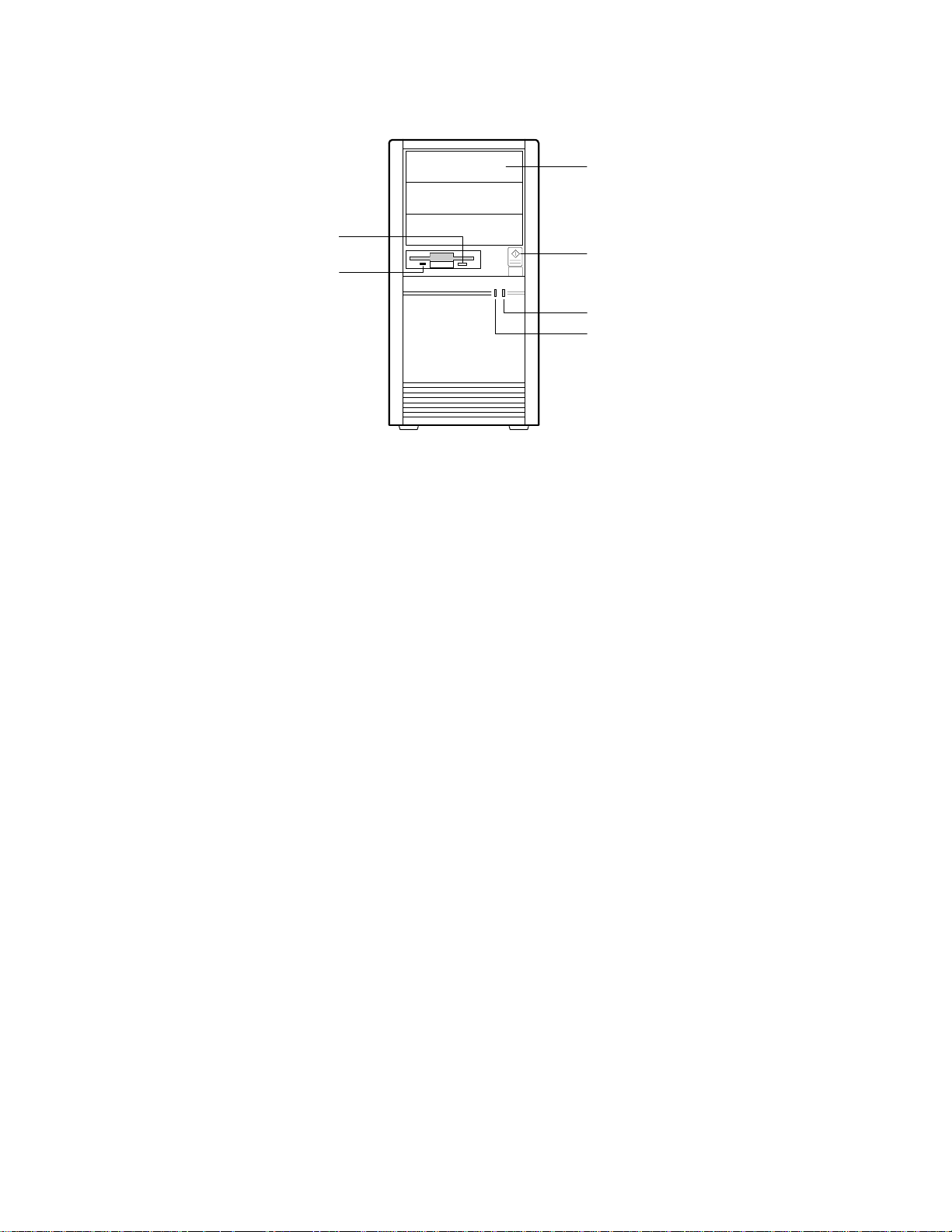
System Front Panel Controls and Indicators
C
A
D
B
E
F
OM04059
Figure 2-2. Mini-Tower Front Panel Controls and Indicators
A. Diskette eject button. Press to eject a diskette from the drive.
B. Diskette drive light. Turns on when the system reads or writes data to a
diskette.
C. Bay for 5.25-inch devices, shown with three plastic filler panels in place.
D. Power control button. Press to turn on the system.
E. Power on/off light. Turns on when the system power is on; blinks when
in power saving/sleep mode.
F. Hard disk light. Turns on when the system reads or writes data to an
IDE hard disk.
System Product Guide 2-5
Page 25
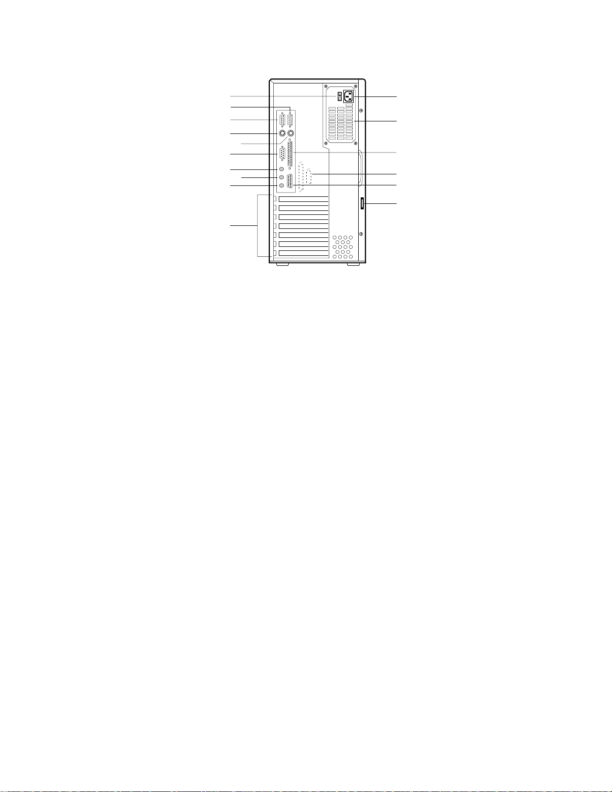
Back Panel Connectors and Features
A
K
B
C
L
D
E
F
G
H
I
M
N
O
P
J
OM04058
Figure 2-3. Mini-Tower Back Panel Connectors and Features
A. Input voltage select switch
B. 9-pin serial port connector COM1
C. 9-pin serial port connector COM2
D. PS/2-style mouse/keyboard connector
E. PS/2-style mouse/keyboard connector
F. Video graphics connector
G. Line-out/speaker jack (may not be fitted)
H. Line-in jack (may not be fitted)
I. Microphone jack (may not be fitted)
J. Add-in board expansion slots
K. Socket for AC power input
L. Power supply fan
M. Parallel port connector
N. Knock outs for additional I/O ports
O. MIDI and dual game port connector (may not be fitted)
P. Padlock slot (padlock not included)
2-6 Installing Your System
Page 26

Turning on the System at First Start-up
To power up the system for the first time, follow these steps:
1. All system components such as a video monitor and keyboard should be
connected before turning on the system. All connections should be
made while the system is off.
2. Connect the female end of the AC power cord into the AC power input
socket at the rear of the system, and plug the male end of the power cord
into a grounded electrical outlet.
3. Turn on power to the monitor.
4. Press the power button at the front of the system (the green power LED
on the front panel will go on). The system will power up and
immediately begin the power-on self test (POST).
When you boot the system, the POST checks the settings stored in CMOS
RAM against the actual hardware configuration. During the memory test,
the POST displays the amount of memory that it has tested. The POST takes
approximately 15 seconds to complete. If you want to go into the Setup
program, press the <F1> key after the POST starts the memory test, but
before the system boots up (see Setup, Chapter 3). Your next step after
booting depends on what POST finds. See the following possibilities:
System Product Guide 2-7
Page 27

What happens What to do
If the settings in CMOS RAM
configuration, and if the POST does not find any
errors, the power-on testing continues.
If the POST finds a fatal error (an error that prevents
the system from continuing the boot process), it
generates a series of beeps. A specific number of
beeps indicates a certain error message.
If the POST finds a non-fatal error (an error that
doesn't stop the boot process from continuing), the
system displays a message in the following format:
Error message line 1
Error message line 2
Press <F1> for Setup,
<Esc> to Boot
If you need to reconfigure the system setup, start
the Setup program.
If you need to begin again, reboot the system. Press <Ctrl + Alt + Del>.
match
the hardware
No action needed.
Record the number of beeps. See
Chapter 7 for a description of the
system beep codes and
troubleshooting procedures.
Locate the error message in
Chapter 7, and take action as
indicated under the explanation for
the error message. If needed, run
the Setup program.
Press <F1> after the POST starts
the memory test,
system boots up.
five seconds to press <F1> to enter
Setup before the boot process
continues.
but before the
You have about
2-8 Installing Your System
Page 28

Resetting the System
To reset the system, press the key sequence:
<Ctrl + Alt + Del>
You can also reset the system by shutting system power off and then
powering back up. To do this:
1. Press the front panel power control button.
2. Wait at least 20 seconds.
3. Press the power button. The system will power up and immediately
begin the power-on self test (POST).
Resetting the system will:
• Clear the system memory
• Restart the power-on self test (POST)
• Reinitialize all peripherals
• Load the operating system
Using Keyboard Shortcuts
The keyboard controller supports using shortcuts to reset the system (soft
boot) and toggle between fast (turbo) and slow CPU speed.
Normally the CPU runs in fast (turbo) mode at its full rated speed. Some
application software requires running the system in slow mode. Changing
to fast mode by using shortcuts may not be supported by some systems or by
some applications, in which case you can specify fast or slow mode by using
the Setup program. For instance the set slow or fast mode keyboard shortcut
will not work if the CPU is being operated in protected mode. (When you
operate Windows in enhanced mode, the CPU is operating in protected
mode.)
The numbers and symbols in the following tables refer to the keys on the
numeric keypad.
System Product Guide 2-9
Page 29

Setting Fast and Slow CPU Modes
To do the following Press at the same time
Set slow (deturbo) mode: (You’ll hear a lowtone beep.)
Set fast (turbo) mode: System runs at the full
rated speed of the CPU. (You’ll hear a hightone beep.)
<Ctrl + Alt + ->
<Ctrl + Alt + +>
Setting Up Add-in Boards and Drives
Chapter 4 explains how to physically install add-in boards and drives. The
system is fully Plug and Play compatible. With Plug and Play capability, the
system automatically configures IDE hard disk drives, diskette drives, PCI
cards, and Plug and Play ISA add-in boards.
■
■
■
■■ ■
2-10 Installing Your System
Page 30

Using the Setup Program
This chapter tells how to use the Setup program that is built into the system
BIOS. The Setup program makes it possible to change and store system
configuration information such as the types of peripherals that are installed,
the boot-up sequence for the system, and enabling or disabling the power
management support. The Setup information is stored in CMOS random
access memory (RAM) and is backed up by a battery when power to the
system is off.
If the system does not operate as described here, see the chapter titled
“Solving Problems” for problem descriptions and error messages.
If you want to go into the Setup program, press the <F1> key after the POST
starts the memory test, but before the system boots up. You have about five
seconds to press <F1> to enter Setup before the boot process continues.
Make a Record of the Setup Configuration
To make sure you have a reference to the Setup values for your system, we
recommend you write down the current settings and keep this record up-todate.
3
System Product Guide 3-1
Page 31

Overview of the Setup Menu Screens
The Setup program initially displays the Main menu screen. In each screen
there are options for modifying the system configuration. Select a menu
screen by pressing the left <←> or right <→> arrow keys. Use the up <↑> or
down <↓> arrow keys to select items in a screen. Use the <Enter> key to
select an item for modification. For certain items, pressing <Enter> will
bring up a subscreen. After you have selected an item, use the arrow keys to
modify the setting.
Setup Menu Screen Description
Main For setting up and modifying some of the basic
options of a PC, such as time, date, diskette drives,
hard drives.
Advanced For modifying the more advanced features of a PC,
such as peripheral configuration and advanced
chipset configuration.
Security For specifying passwords that can be used to limit
access to the system.
Exit For saving or discarding changes.
Setup Subscreen Description
Floppy Options For configuring your diskette drives.
IDE Configuration For configuring your hard drives.
Boot Options For modifying options that affect the system boot
up, such as the boot sequence.
Peripheral Configuration For modifying options that affect the serial ports, the
parallel port, and the disk drive interfaces.
Advanced Chipset Configuration For modifying options that affect memory and
system busses.
Power Management Configuration For accessing and modifying Advanced Power
Management (APM) options.
Plug and Play Configuration For modifying options that affect the system’s Plug
and Play capabilities.
3-2 Using the Setup Program
Page 32

Overview of the Setup Keys
The following keys have special functions in the BIOS Setup program.
Setup Key Description
<F1> Pressing the <F1> key brings up a help screen for the current
item.
<Esc> Pressing the <Esc> key takes you back to the previous screen.
Pressing <Esc> in the Main, Advanced, Security, or Exit screen
allows you to Exit Discarding Changes (see later in this chapter).
<Enter> Pressing the <Enter> key selects the current item or option.
<↑> Pressing the up arrow <↑> key changes the selection to the
previous item or option.
<↓> Pressing the down arrow <↓> key changes the selection to the
next item or option.
<←> <→> Pressing the left <←> or right arrow <→> keys in the Main,
Advanced, Security, or Exit menu screens changes the menu
screen. Pressing either key in a subscreen does nothing.
<F5> Pressing the <F5> key allows you to Load Setup Defaults (see
later in this chapter).
<F6> Pressing the <F6> key allows you to Discard Changes (see later
in this chapter).
<F10> Pressing the <F10> key allows you to Exit Saving Changes (see
later in this chapter).
System Product Guide 3-3
Page 33

Main BIOS Setup Screen
This section describes the Setup options found on the main menu screen. If
you select certain options from the main screen (e.g., Boot Options), the
Setup program switches to a subscreen for the selected option.
System Date
Specifies the current date. Select the month from a pop-up menu.
System Time
Specifies the current time.
Floppy Options
When selected, this pops up the Floppy Options menu.
Primary IDE Master
Reports if a IDE device is connected to the system. When selected, this
brings up the IDE Configuration subscreen.
Primary IDE Slave
Reports if a IDE device is connected to the system. When selected, this
brings up the IDE Configuration subscreen.
Secondary IDE Master
Reports if a IDE device is connected to the system. When selected, this
brings up the IDE Configuration subscreen.
Secondary IDE Slave
Reports if a IDE device is connected to the system. When selected, this
brings up the IDE Configuration subscreen.
Language
Specifies the language of the text strings used in the Setup program and the
BIOS. The options are any installed languages.
3-4 Using the Setup Program
Page 34

Boot Options
When selected, this brings up the Boot Options subscreen.
Video Mode
Reports the video mode. There are no options.
Mouse
Reports if a mouse is installed or not. There are no options.
Base Memory
Reports the amount of base memory. There are no options.
Extended Memory
Reports the amount of extended memory. There are no options.
System Product Guide 3-5
Page 35

Floppy Options Subscreen
Floppy A:
Reports if a diskette drive is connected to the system. There are no options.
Floppy B:
Reports if a second diskette drive is connected to the system. There are no
options.
Floppy A: Type
Specifies the physical size and capacity of the diskette drive. The options are
Disabled, 360 KB, 5.25-inch; 1.2 MB, 5.25-inch; 720 KB, 3.5-inch; 1.44/1.25
MB, 3.5-inch; 2.88 MB, 3.5-inch. The default is 1.44/1.25 MB, 3.5-inch.
Floppy B: Type
Specifies the physical size and capacity of the diskette drive. The options are
Disabled, 360 KB, 5.25-inch; 1.2 MB, 5.25-inch; 720 KB, 3.5-inch; 1.44/1.25
MB, 3.5-inch; 2.88 MB, 3.5-inch. The default is Disabled.
3-6 Using the Setup Program
Page 36

IDE Configuration Subscreen
IDE Device Configuration
Used to manually configure the device or have the system auto configure it.
The options are Auto Configured, User Definable, and Disabled. The default
is Auto Configured. If you select User Definable then the Number of
Cylinders, Number of Heads, and Number of Sectors items can be modified.
Number of Cylinders
If IDE Device Configuration is set to User Definable, you must type the
correct number of cylinders for your hard disk. If IDE Device Configuration
is set to Auto Configured, this reports the number of cylinders for your hard
disk and cannot be modified.
Number of Heads
If IDE Device Configuration is set to User Definable, you must type the
correct number of heads for your hard disk. If IDE Device Configuration is
set to Auto Configured, this reports the number of heads for your hard disk
and cannot be modified.
Number of Sectors
If IDE Device Configuration is set to User Definable, you must type the
correct number of sectors for your hard disk. If IDE Device Configuration is
set to Auto Configured, this reports the number of sectors for your hard disk
and cannot be modified.
Maximum Capacity
Reports the maximum capacity of your hard disk. It is calculated from the
number of cylinders, heads, and sectors. There are no options here.
System Product Guide 3-7
Page 37

IDE Translation Mode
Specifies the IDE translation mode. The options are Standard CHS (standard
cylinder head sector — less than 1024 cylinders), Logical Block, Extended
CHS (extended cylinder head sector — greater than 1024 cylinders), and
Auto Detected (BIOS detects IDE drive support for LBA). The default is
Auto Detected.
CAUTION
!
▲
▲
Do not change this from the option selected when the hard
drive was formatted. Changing the option can result in
corrupted data.
Multiple Sector Setting
Sets the number of sectors transferred by an IDE drive per interrupt
generated. The options are Disabled, 4 Sectors/Block, 8 Sectors/Block, or
Auto Detected. The default is Auto Detected. Check the specifications for
your hard disk drive to determine which setting provides optimum
performance for your drive.
Fast Programmed I/O Modes
Sets how fast transfers on the IDE interface occur. The options are Disabled
or Auto Detected. The default is Auto Detected. If set to Disabled, transfers
occur at a less than optimized speed. If set to Auto Detected, transfers occur
at the drive’s maximum speed.
3-8 Using the Setup Program
Page 38

Boot Options Subscreen
This section describes the options available on the Boot Options subscreen.
First Boot Device
Sets which drive the system checks first to find an operating system to boot
from. The following options are available:
Floppy The system checks the Floppy drive first.
Hard Disk The system checks the Hard Disk first.
CD ROM The system checks the CD ROM first.
Network The system checks the Network first.
Disabled
For First Boot Device, the default is Floppy. If the system is unable to boot
from the selected boot device, the system will check the device selected for
Second Boot Device.
Second Boot Device
The options are Floppy, Hard Disk, CD ROM, Network, and Disabled.
Default is Hard Disk. If the system is unable to boot from the selected boot
device, the system will check the device selected for Third Boot Device.
Third Boot Device
The options are Floppy, Hard Disk, CD ROM, Network, and Disabled. The
default is disabled. If the system is unable to boot from the selected boot
device, the system will check the device selected for Fourth Boot Device.
Fourth Boot Device
The options are Floppy, Hard Disk, CD ROM, Network, and Disabled. The
default is Disabled.
System Cache
Enables or disables both the primary and the secondary cache memory. The
options are Enabled or Disabled. The default is Enabled.
System Product Guide 3-9
Page 39

Boot Speed
Sets the system’s boot speed. The options are Deturbo and Turbo. The
default is Turbo. If Turbo is selected, boot-up occurs at full speed. If
Deturbo is selected, the board operates at a slower speed.
Num Lock
Sets the beginning state of the Num Lock feature on your keyboard. The
options are On and Off. The default is Off.
Setup Prompt
Turns on (or off) the “Press <F1> Key if you want to run Setup” prompt
during the power-up sequence. The options are Enabled and Disabled. The
default is Enabled.
✏
Note
This option has no effect on your ability to access the Setup
program. It only toggles the prompt.
Typematic Rate Programming
Sets the typematic rates. The options are Default and Override. The default
is Default. Choosing Override enables Typematic Rate Delay and Typematic
Rate.
Typematic Rate Delay
Sets how long it takes for the key-repeat function to start when you hold
down a key on the keyboard. The options are 250, 500, 750, and 1000
millisecond delays. The default is 250. If Typematic Rate Programming is
set to Default, this option will not be visible.
Typematic Rate
Sets the speed at which characters repeat when you hold down a key on the
keyboard. The higher the number, the faster the characters repeat. The
options are 6, 8, 10, 12, 15, 20, 24, and 30 characters per second. The default
is 6. If Typematic Rate Programming is set to Default, this option will not be
visible.
3-10 Using the Setup Program
Page 40

Advanced Screen
This section describes the Setup options found on the Advanced menu
screen. If you select certain options from the Advanced screen (e.g.,
Peripheral Configuration), the Setup program switches to a subscreen for the
selected option. Subscreens are described in the sections following the
description of the Advanced screen options.
Processor Type
Reports the CPU type. There are no options.
Processor Speed
Reports the CPU clock speed. There are no options.
Cache Size
Reports the size of the secondary cache. There are no options. If your
system contains no L2 cache, this item will not appear.
Peripheral Configuration
When selected, this brings up the Peripheral Configuration subscreen.
Advanced Chipset Configuration
When selected, this brings up the Advanced Chipset Configuration
subscreen.
Power Management Configuration
When selected and enabled, this brings up the Advanced Power
Management subscreen.
Plug and Play Configuration
When selected, this brings up the Plug and Play Configuration subscreen.
System Product Guide 3-11
Page 41

Peripheral Configuration Subscreen
This section describes the screens for the peripheral configuration subscreen.
Configuration Mode
Enables you to choose between setting the peripheral configuration yourself,
or having the system do it. The options are Auto and Manual. The default is
Auto.
When Auto is selected, the system peripherals are automatically configured
during power up. The options below for PCI IDE Interface, Floppy Interface,
Serial Port 1 and Serial Port 2 Addresses, Serial Port 2 IR Mode, and the
Parallel Port Address cannot be modified. The settings displayed for those
options reflect the current state of the hardware.
PCI IDE Interface
Enables or disables the PCI IDE hard disk interface. The options are Enabled
and Disabled. The default is Enabled. (If Configuration Mode is set to Auto,
this option cannot be modified.)
Floppy Interface
Enables or disables the diskette drive interface. The options are Enabled and
Disabled. The default is Enabled. (If Configuration Mode is set to Auto, this
option cannot be modified.)
Serial Port 1 Address
Selects the address of the serial port. The options are Disabled; COM1, 3F8h,
IRQ4; COM2, 2F8h, IRQ3; COM3, 3E8h, IRQ4; and COM4, 2E8h, IRQ3. If the
Configuration Mode is set to Auto, the Setup program assigns the first free
COM port (normally COM1, 3F8h) as the serial port 1 address, regardless of
what is selected under the Serial Port 1 Address option. (If Configuration
Mode is set to Auto, this option cannot be modified.)
3-12 Using the Setup Program
Page 42

Serial Port 2 Address
Selects the address of the serial port. The options are Disabled; COM1, 3F8h,
IRQ4; COM2, 2F8h, IRQ3; COM3, 3E8h, IRQ4; and COM4, 2E8h, IRQ3. If the
Configuration Mode is set to Auto, the Setup program assigns the first free
COM port (normally COM2, 2F8h) as the serial port 2 address, regardless of
what is selected under the Serial Port 2 Address option. (If Configuration
Mode is set to Auto, this option cannot be modified.)
✏
Note
If either serial port address is set, the address it is set to will
not appear in the options dialog box of the other serial port.
If an ATI mach32† or an ATI mach64† video controller is
active, the COM4, 2E8h, IRQ3 address will not appear in the
options dialog box of either serial port.
Serial Port 2 IR Mode
Makes Serial Port 2 available to infrared applications. The options are
Enabled and Disabled. The default is Disabled. (If Configuration Mode is
set to Auto, this option cannot be modified.)
Parallel Port Address
Selects the address and IRQ of the parallel port. The options are Disabled;
LPT3, 3BCh, IRQ7; LPT1, 378h, IRQ7; LPT2, 278h, IRQ7; LPT3, 3BCh, IRQ5
LPT1, 378h, IRQ5; and LPT2, 278h, IRQ5. If the Configuration Mode is set to
Auto, the setup program assigns LPT1, 378h, IRQ7 as the parallel port
address, regardless of what is selected under the Parallel Port Address
option. (If Configuration Mode is set to Auto, this option cannot be
modified.)
Parallel Port Mode
Selects the mode for the parallel port. The options are Compatible, Bidirectional, ECP, and EPP. The default is Compatible. Compatible means
the parallel port operates in AT-compatible mode. Bi-directional means the
parallel port operates in bi-directional PS/2-compatible mode. EPP and ECP
mean the parallel port operates high-speed, bi-directionally. This option is
not affected by the Configuration Mode field above.
System Product Guide 3-13
Page 43

Advanced Chipset Configuration Subscreen
This section describes the options available on the Advanced Chipset
Configuration Subscreen.
Base Memory Size
Sets the size of the base memory. The options are 512 KB and 640 KB. The
default is 640 KB.
ISA LFB Size
Sets the size of the linear frame buffer. The options are Disabled and 1 MB.
The default is Disabled. If this is set to 1 MB, then the ISA LFB Base Address
field will appear.
ISA LFB Base Address
Reports the base address of the LFB. There are no options. This field will
not appear if the ISA LFB Size is set to Disabled.
Video Palette Snoop
Controls the ability of a primary PCI graphics controller to share a common
palette with an ISA add-in video card. The options are Enabled and
Disabled. The default is Disabled.
Latency Timer (PCI Clocks)
Sets the length of time an agent on the PCI bus can hold the bus when
another agent has requested the bus. Valid numbers are between 0 and 256.
The default is 66.
PCI Burst
Enables or disables bursting on the PCI bus. When disabled, forces normal
PCI cycles. When enabled, allows PCI cycles to burst. Must be disabled
with some graphics cards that don’t support burst cycles. If the display
appears to be corrupted, disable this field.
3-14 Using the Setup Program
Page 44

Bank O SIMM Detected
Reports the type of memory found in the bank 0 SIMM slots. There are no
options.
Bank 1 SIMM Detected
Reports the type of memory found in the bank 1 SIMM slots. There are no
options.
System Product Guide 3-15
Page 45

Power Management Configuration Subscreen
This section describes the options available on the Power Management
Subscreen.
Advanced Power Management
Enables or disables the Advanced Power Management (APM) support in
your system’s BIOS. The options are Enabled and Disabled. The default is
Enabled. Power Management will only work with APM-capable operating
systems to manage power consumption in your system. If Advanced Power
Management is set to Disabled, none of the fields in the Advanced Power
Management subscreen will be visible.
IDE Drive Power Down
Sets any IDE drives to spin down when the system goes into power managed
mode. The options are Enabled and Disabled. The default is Enabled.
VESA Video Power Down
Sets the command issued to your graphics controller when the system goes
into power managed mode. The command options are Disabled, Standby,
Suspend, and Sleep. The default is Sleep.
Inactivity Timer
Sets how long the system must be inactive before it enters power managed
mode. Enter the number of minutes. The range is 0 to 255 minutes. The
default is 10 minutes.
Hot Key
Sets the hot key that, when pressed while holding down the <Ctrl> and
<Alt> keys, causes the system to enter power managed mode. All alphabetic
keys are valid.
3-16 Using the Setup Program
Page 46

Plug and Play Configuration Subscreen
This section describes the options found on the Plug and Play configuration
subscreen.
Configuration Mode
Sets how the BIOS gets information about ISA cards that do not have Plug
and Play capabilities. The options are Use Setup Utility and Use ICU (ISA
Configuration Utility). The default is Use Setup Utility.
If Use ICU is selected, the BIOS will depend on run-time software to ensure
that there are no conflicts between ISA boards with Plug and Play
capabilities and those without. Choosing Use ICU enables Boot with PnP OS
and disables all other options.
Boot with PnP OS
Enables the PC to boot with an operating system capable of managing Plug
and Play add-in cards. The options are None, Other, and Windows 95. The
default is Windows 95. If Configuration Mode (above) is set to Use Setup
Utility, this option will not be visible.
ISA Shared Memory Size
Enables you to “unshadow” a block of the upper memory area. The options
are Disabled, 16 KB, 32 KB, 48 KB, 64 KB, 80 KB, and 96 KB. The default is
Disabled. If this is set to Disabled, the ISA Shared Memory Base Address
(described below) will not be visible.
Shadowing is a technique that copies a block of memory from an add-in
card’s ROM to the same address in system memory. This provides faster
access and achieves higher performance. By default, all upper memory is
shadowed.
ISA Shared Memory Base Address
Sets the base address for the ISA Shared Memory. The options are C8000h,
CC000h, D0000h, D4000h, D8000h, and DC000h. The default is C8000h. This
setting could affect the ISA Shared Memory Size item. The value entered in
the ISA Shared Memory Size item cannot extend to the E0000h address. For
example, if a size of 64K was selected, options D4000h, D8000h, and DC000h
will not be available.
System Product Guide 3-17
Page 47

IRQ 3, 4, 5, 7, 9, 10, 11, 12
Sets the status of the IRQ. The options are Available and Used By ISA Card.
The default is Available. The PCI auto-configuration code looks here to see
if these interrupts are available for use by a PCI add-in board. If an interrupt
is available, the PCI auto-configuration code can assign the interrupt to be
used by the system. If your system contains an ISA agent that uses one of
these interrupts, select Used By ISA Card for that interrupt.
3-18 Using the Setup Program
Page 48

Security Screen
This section describes the two access modes that can be set using the options
found on the Security screen, and then describes the Security screen options
themselves.
Administrative and User Access Modes
The options on the Security screen menu make it possible to restrict access to
the Setup program by enabling you to set passwords for two different access
modes: Administrative mode and User mode.
In general, Administrative mode has full access to the Setup options,
whereas User mode has restricted access to the options. Thus, by setting
separate Administrative and User passwords, a system administrator can
limit who can change critical Setup values. The actual limitations depend on
whether either the Administrative or User passwords or both are set. (See
the table below for a description of how the passwords actually work
together.)
To limit access to who can boot the system, set the User password. This is
the password that the system asks for before booting. If only the
Administrative password is set, the system boots up without asking for a
password. If both passwords are set, you can enter either password to boot
the system.
The following table shows the effects of setting the Administrative and User
passwords. (The table is for reference only, and is not shown on the Security
screen.) In the table, the statement “Can change a limited number of
options” means you can change the system date and time, the power
management hot key, the User password, the security hot key, and
unattended start.
Administrative and User Password Functions
Administrative mode
Password Set
Neither Can change all options* Can change all options* None
Administrative only Can change all options Can change a limited
User only N/A Can change all options User
Both Can change all options Can change a limited
* If no password is set, any user can change all Setup options.
System Product Guide 3-19
can . . . User mode can . . .
number of options
number of options
Password Required
During Boot Process
None
Administrative or User
Page 49

Security Screen Options
User Password is
Reports if there is a User password set. There are no options.
Administrative Password is
Reports if there is an Administrative password set. There are no options.
Set User Password
Sets the User password. The password can be up to seven alphanumeric
characters.
Set Administrative Password
Sets the Administrative password. The password can be up to seven
alphanumeric characters.
Unattended Start
Controls when the security password is requested. The options are Enabled
and Disabled. The default is Disabled. The User password must be enabled
before you can enable this option. If Enabled is selected, the system boots,
but the keyboard will be locked until the User password is entered.
Security Hot Key (CTRL-ALT-)
Sets a hot key that, when pressed, locks the keyboard until the User
password is entered. The Keyboard LED’s flash to indicate that the
keyboard is locked. When you enter the User password, you do not have to
press the <Enter> key.
3-20 Using the Setup Program
Page 50

Exit Screen
This section describes the different ways to exit and save or not save changes
made in the Setup program.
Exit Saving Changes
Saves the changes to CMOS RAM and exits the Setup program. You can also
press the <F10> key anywhere in the Setup program to do this.
Exit Discarding Changes
Exits the Setup program without saving any changes. This means that any
changes made while in the Setup program are discarded and NOT SAVED.
Pressing the <Esc> key in any of the four main screens will do this.
Load Setup Defaults
Resets all of the setup options to their defaults. You can also press the <F5>
key anywhere in the Setup program to do this.
This selection loads the default Setup values from the ROM table.
Discard Changes
Discards any changes you made during the current Setup session without
exiting the program. You can also press the <F6> key anywhere in the Setup
program to do this.
This selection loads the CMOS RAM values that were present when the
system was turned on.
■
■
■
■■ ■
System Product Guide 3-21
Page 51

Page 52

Taking Your System Apart
This chapter tells how to take apart and reassemble the major parts of the
system. Chapter 5 describes how to remove and install system board
components.
Before You Begin
• Be sure to do each procedure in the correct order.
• The procedures (and warnings) for removing and reinstalling the side
covers are assumed to precede all other procedures described in this
chapter.
• Set up an equipment log to record the system model and serial numbers,
all installed options, and other information about the system. If you
need this information, it will be easier to consult the log than to open up
and examine the system.
• You will need a Phillips screwdriver (#2 bit). We recommend that you
use an antistatic wrist strap and a conductive foam pad when working
on the system.
! WARNINGS
▲
The procedures in this chapter assume familiarity with the
general terminology associated with personal computers
and with the safety practices and regulatory compliance
required for using and modifying electronic equipment.
The power supply in this system contains no userserviceable parts. To avoid personal injury or damage to
your equipment, refer repair or replacement of the power
supply to qualified personnel only. All other areas and
components of this system are considered user-accessible.
4
System Product Guide 4-1
Page 53

CAUTIONS
!
▲
▲
Disconnect the system from its power source and from any
telecommunications links, networks or modems before
doing any of the procedures described in this chapter.
Failure to disconnect power, telecommunications links,
networks or internal modems before you open the system
or do any procedures can result in personal injury or
equipment damage.
Do not operate the system with the cover removed.
Always replace the cover before turning on the system.
The total power draw on the system must not exceed the
specifications for the power supply. See Chapter 7 for the
power supply specifications.
Electrostatic discharge (ESD) can damage disk drives, add-in
boards, and other components. Conduct the procedures
described in this chapter only at an ESD workstation. If
such a station is not available, you can provide some ESD
protection by wearing an antistatic wrist strap and attaching
it to a metal part of the system chassis.
Add-in boards can be extremely sensitive to ESD and always
require careful handling. After removing the board from its
protective wrapper or from the system, place the board flat
on a grounded, static-free surface, component-side up. Use
a conductive foam pad if available, but not the board
wrapper. Do not slide the board over any surface.
4-2 Taking Your System Apart
Page 54

Removing the Side cover
CAUTION
!
▲
▲
1. Observe the precautions in “Before You Begin.”
2. Turn the system power off with the power enable switch at the rear
3. Put identification tags on all cables attached to the system.
4. Disconnect the cables from the system.
5. If you installed a padlock on the back of the system, unlock the padlock
6. The side cover is on the left side of the system (as viewed from the front).
7. Pull the cover so it slides backwards. Make sure that cover clears the
8. Pull the bottom of the cover out (like it was hinged at the top) until the
9. Slide the cover up until it comes free of the chassis.
For proper cooling and airflow, do not operate the system
with the cover removed. Always replace the cover before
turning on the system.
panel and unplug the AC power cord from the back of the chassis.
and remove it (Figure 4-1, A).
The cover is secured with two screws at the rear of the system. Remove
the screws (Figure 4-1, B).
padlock slot.
bottom metal tabs clear their slots.
System Product Guide 4-3
Page 55

B
A
A
OM04061
Figure 4-1. Removing the Side cover
4-4 Taking Your System Apart
Page 56

Installing the Side cover
1. Observe the precautions in “Before You Begin.”
2. Check that you have not left any tools or loose parts inside the system.
Check that everything is properly installed and tightened.
3. Insert the metal tabs on the top of the side cover into their slots on the
chassis.
4. Insert the metal tabs on the bottom of the side cover into their slots on
the chassis.
5. Slide the cover forward as far as it will go.
6. Replace and tighten the screws securing the side cover to the chassis.
7. For security, you may want to install a padlock on the system to prevent
unauthorized removal of the cover from the chassis.
8. Reconnect all cables to the system.
Removing the Bezel
1. Observe the precautions in “Before You Begin.”
2. Remove the side cover.
3. Remove the screw securing the bezel to the chassis (Figure 4-2, A).
4. Squeeze the two tabs so they clear their slots (Figure 4-2, B).
5. Pull the left side of the bezel out (like it was hinged on the right side)
until the retaining screw tab, and the power button clear the chassis
(Figure 4-2, C).
6. Slide the bezel to the right until it comes free (Figure 4-2, D).
System Product Guide 4-5
Page 57

D
A
B
Figure 4-2. Removing the Bezel
C
OM04062
Installing the Bezel
1. Observe the precautions in “Before You Begin.”
2. Insert the metal tabs on the right side into their slots.
3. Squeeze the bezel and the chassis together along the left side so the tabs
snap into their slots.
4. Replace and tighten the bezel retaining screw.
5. Replace the side cover.
4-6 Taking Your System Apart
Page 58

Add-in Board Considerations
The next few procedures tell how to remove and install slot covers and addin boards. As an aid to installing boards in your system, this section
describes the arrangement and numbering conventions for the slot
connectors on the system board.
ISA-compatible add-in boards can be installed in any of the system board
ISA slots. PCI-compatible add-in boards can be installed in any of the PCI
slots.
CAUTIONS
!
▲
▲
Do not overload the system board by installing add-in
boards that draw excessive current. The system is designed
to provide 2 A (average) of +5 V power for each board in the
system. The total +5 V current draw in a fully-loaded
system (all add-in board slots filled) must not exceed 14 A.
Add-in boards can be extremely sensitive to ESD and always
require careful handling. Hold the board by the edges only;
do not touch the electronic components or gold connectors.
After removing a board from its protective wrapper or from
the system, place it flat on a grounded, static-free surface,
component-side up. Do not slide the board over any
surface.
System Product Guide 4-7
Page 59

6
6
5
4
3
2
1
OM0421
Figure 4-3. System Slot Numbering Convention
Figure 4-3 shows the numbering convention for the connectors on the system
board and for the slot openings on the back panel. The numbers are for
reference only and are not actually printed on the system board or the back
panel. Notice that slot opening 3 in the back panel can hold either a PCI or
an ISA board (but not both at the same time).
4-8 Taking Your System Apart
Page 60

Removing Expansion Slot Covers
There are two kinds of slot covers, breakout slot covers and standard slot
covers. The procedure covers both kinds.
Removing Breakout Slot Covers
1. Observe the precautions in “Before You Begin.”
CAUTIONS
!
▲
▲
2. Insert a #2 bit Phillips screwdriver into the top of the slot cover. Move
Be careful to not damage components on the system board
or add-in boards when doing this procedure. You may need
to remove add-in boards that are next to the slot cover you
want to remove.
the screwdriver and slot cover toward the inside of the chassis until the
slot cover breaks away from the chassis (Figure 4-4). Lift the slot cover
up and out.
OM04335
Figure 4-4. Removing a Breakout Expansion Slot Cover
System Product Guide 4-9
Page 61

Removing Standard Slot Covers
1. Observe the precautions in “Before You Begin.”
CAUTION
!
▲
▲
2. Remove the expansion slot screw from the top of the slot cover (Figure 4-
Be careful to not damage components on the system board
or add-in boards when doing this procedure. You may need
to remove add-in boards that are next to the slot cover you
want to remove.
5). Lift the cover up and out. Save the slot cover in case you remove the
board later.
OM04178
Figure 4-5. Removing an Expansion Slot Cover
4-10 Taking Your System Apart
Page 62

Installing an Expansion Slot Cover
1. Observe the precautions in “Before You Begin.”
2. Using one of the original slot covers, insert the cover into the slot at the
base of the chassis and secure it with a screw.
✏
Note
If you no longer have the original slot cover, use a standard
metal slot cover. The bottom end of the cover fits inside the
chassis, flush with the chassis wall, and the top end secures
to the board guide with a screw.
Installing an Add-in Board
1. Observe the precautions in “Before You Begin.”
2. Remove the expansion slot cover from the slot you plan to use. Save the
cover and screw to reinstall if you decide not to install a board in that
slot.
3. Remove the board from its wrapper and place it on a grounded, staticfree surface.
4. Set any board jumpers or switches according to the manufacturer’s
instructions.
5. Hold the board by its top edge or upper corners and firmly press the
board into the connector on the system board (Figure 4-6).
6. Align the rounded notch in the retaining bracket with the threaded hole
in the expansion slot frame (Figure 4-6). The retaining bracket fits into
the space that was occupied by the expansion slot cover.
7. Insert a screw, but push the notch against the screw before tightening.
Otherwise the bracket may interfere with the bracket of an adjacent slot
cover or with another add-in board.
8. Connect cables (if any are needed) to the installed board.
System Product Guide 4-11
Page 63

Figure 4-6. Installing an Add-in Board
Removing an Add-in Board
OM04179
✏
1. Observe the precautions in “Before You Begin.”
2. Disconnect any cables attached to the add-in board you are removing.
3. Remove the screw that holds the board retaining bracket to the chassis.
4. Hold the board at each end, and carefully rock it back and forth until the
4-12 Taking Your System Apart
Note
Expansion slot covers must be installed on all vacant slots to
maintain the electromagnetic emissions characteristics of the
system and to ensure proper cooling of the system
components.
edge connectors pull free. Make sure that you do not scrape the board
against other components.
Page 64

5. Store the board in an antistatic wrapper.
6. If you disconnected cables from the board and you are not reinstalling
this board or one like it, remove the cables from the system.
7. Install an expansion slot cover over the vacant slot.
Removing the 3.5-inch Drive Carrier
1. Observe the precautions in “Before You Begin.”
2. Disconnect the power cable and the ribbon data cable from any drives in
the carrier.
3. Remove the two screws that secure the carrier to the 5.25-inch drive bay
(Figure 4-7, A and B).
4. Slide the carrier back until the tabs hit their stops (Figure 4-7).
5. Pull the carrier away from the 5.25-inch drive bay and remove it from
the chassis.
A
A
B
OM04079
Figure 4-7. Removing the 3.5-inch Drive Carrier
System Product Guide 4-13
Page 65

Installing the 3.5-inch Drive Carrier
1. Observe the precautions in “Before You Begin.”
2. Insert the tabs on carrier into their slots on the bottom and side of the
5.25-inch drive bay.
3. Slide the carrier forward until the screw hole in the front drive bay and
the hole in the carrier line up.
4. Insert the two screws that secure the carrier to the front drive bay into
their holes and tighten them. (If you removed the front bezel, replace it
before tightening the screw.)
5. If there is a drive in the carrier, attach the power cable and the ribbon
data cable to the drive.
Removing the Floppy Disk Drive
1. Observe the precautions in “Before You Begin.”
2. Remove the 3.5-inch drive carrier from the system.
3. Remove the four screws holding the drive to the drive carrier
(Figure 4-8, B).
4. Slide the drive out of the drive carrier.
5. If you do not plan to replace the drive you just removed, and there are
no other diskette drives on the same data cable, disconnect the cable
from the system board.
6. Replace the carrier in the system.
CAUTION
!
▲
▲
4-14 Taking Your System Apart
If you are not reinstalling a 3.5-inch diskette drive, cover the
empty bay with a filler panel and a shield to maintain the
electromagnetic-interference characteristics of the system
and to ensure proper cooling inside.
Page 66

C
A
Figure 4-8. Removing the Floppy Disk Drive
Installing a Floppy Disk Drive
1. Observe the precautions in “Before You Begin.”
2. Remove the 3.5-inch drive carrier from the system.
3. Remove the floppy disk drive from its protective wrapper and place it
on an antistatic surface.
4. Set any drive jumpers or switches according to the manufacturer’s
instructions.
5. Slide the floppy drive into the 3.5-inch drive carrier. Line the holes on
the carrier up with the screw holes on the drive.
6. Insert and tighten four screws of the appropriate size and length (not
supplied).
7. Install the 3.5-inch drive carrier.
8. Attach the power cable and the data cable to the drive.
B
OM04081
System Product Guide 4-15
Page 67

Installing a Drive in the 3.5-inch Drive Carrier
1. Observe the precautions in “Before You Begin.”
2. Remove the 3.5-inch drive carrier.
3. Remove the drive from its protective wrapper and place it on an
antistatic surface.
4. Set any jumpers, switches, or terminating resistors according to the
manufacturer’s instructions.
5. Slide the drive into the carrier until the screw holes line up.
6. Secure the drive to the carrier with four screws (Figure 4-9, C) of the
appropriate size and length (not supplied).
7. Connect a power connector from the power supply to the drive. If the
drive is an IDE drive, connect the data cable between the drive and one
of the PCI/IDE connectors on the system board. If the drive is a nonIDE type, refer to the drive manufacturer’s instructions for connecting a
data cable and interface board and for configuring the drive.
✏
8. Replace the 3.5-inch drive carrier.
4-16 Taking Your System Apart
Note
The system board provides two PCI/IDE headers for
connecting IDE hard drives. You can connect up to two IDE
drives (on the supplied cable) to each PCI/IDE header. If
one PCI/IDE header already has two drives connected to it,
you can connect additional IDE drives to the second
PCI/IDE header.
Page 68

A
B
C
OM04078
Figure 4-9. Installing an Internal Drive
Removing a Drive from the 3.5-inch Drive Carrier
1. Observe the precautions in "Before You Begin."
2. Disconnect the data cables and power cables from any drives in the rear
drive carrier.
3. Remove the 3.5-inch drive carrier from the system.
4. Remove the four screws that attach the drive to the carrier.
5. Remove the drive from the carrier and place it on an antistatic surface.
6. Replace the 3.5-inch drive carrier.
System Product Guide 4-17
Page 69

Installing a 5.25-inch Device
CAUTIONS
!
▲
▲
1. Observe the precautions in “Before You Begin.”
2. Remove one of the EMI shields from the chassis (Figure 4-10, A). Save
3. If the device will be accessible from the front, remove the screws
4. Remove the device from its protective wrapper and place it on an
If you are installing a device that should not be accessible
from the front, do not remove the EMI shield and filler
panel.
When removing a plastic filler panel, be careful not to break
the panel or its tabs. Save all EMI shields and filler panels
for reuse if necessary.
the shield in case you need to it them later.
securing the filler panel to the bezel (Figure 4-10, B). Remove the filler
panel. Save the filler panel and screw in case you need to replace them
later.
antistatic surface. Record the model and serial number in the equipment
log.
4-18 Taking Your System Apart
Page 70

A
B
OM04066
Figure 4-10. Removing EMI Shields and Filler Panels
5. Set any device jumpers or switches according to the manufacturer’s
instructions.
6. Use two screws (not supplied) plus the EMC caps to attach a plastic,
snap-in slide rail to each side of the device (Figure 4-11, A, B, C).
System Product Guide 4-19
Page 71

A
B
OM04408
Figure 4-11. Installing the Snap-In Slide Rails
7. Position the drive so that the plastic slide rails on each side of the device
engage the front peripheral bay guide rails.
8. Push the drive into the bay until the slide rails lock in place.
9. Connect power and data cables to the device.
4-20 Taking Your System Apart
Page 72

OM04080
Figure 4-12. Installing a 5.25-inch Device
10. If the device won’t be accessible from the front, replace the EMI shield.
11. Replace the bezel.
System Product Guide 4-21
Page 73

Removing a 5.25-inch Device
1. Observe the precautions in “Before You Begin.”
2. Disconnect the power and data cables attached to the device.
3. While squeezing the protruding plastic snap-in rails attached to the
device towards each other (Figure 4-12), carefully slide the device out of
the bay.
4. Replace the EMI shield and secure it to the chassis with a screw.
5. Replace the filler panel and secure it to the bezel with two screws.
Removing the System Board
1. Observe the precautions in “Before You Begin.”
2. Disconnect all internal cables connected to any add-in boards installed in
the expansion slots.
3. Remove all add-in boards.
4. Disconnect all internal cables connected to the system board.
5. Remove the nine retaining screws and set them aside (Figure 4-13).
6. Carefully pop the board off of the snap-in standoff located near the card
retaining bracket (be careful not to flex the board) and lift the board out
of the chassis (Figure 4-13).
CAUTION
!
▲
▲
Be careful not to scrape any board components. Do not flex
the board. Place the board on a grounded, static-free surface
or in an antistatic protective wrapper.
4-22 Taking Your System Apart
Page 74

Figure 4-13. Removing the System Board
Installing the System Board
1. Observe the precautions in “Before You Begin.”
2. Position the system board over the threaded standoffs inside the chassis
and press it onto the snap-in standoff (Figure 4-13).
3. Secure the board to the chassis with nine screws.
4. Connect all internal cables to the system board.
5. Install any add-in boards.
6. Connect all internal cables that go to the add-in boards installed in the
expansion slots.
A
OM04065
■
■
■
■■ ■
System Product Guide 4-23
Page 75

Page 76

Installing and Configuring
This chapter describes the following:
• The system board layout
• The system board configuration jumpers
• Installing an OverDrive processor upgrade
• Installing single in-line memory modules (SIMMs)
• Installing video DRAM (for systems with the optional video subsystem)
• Replacing the battery
Before You Begin
• Be sure to do each procedure in the correct order.
• The procedures (and warnings) for removing and reinstalling the system
cover are assumed to precede all other procedures described in this
chapter. Chapter 4 tells how to remove the system cover.
• Set up an equipment log to record the system model and serial numbers,
all installed options, and other information about the system. If you
need this information, it will be easier to consult the log than to open up
and examine the system.
• You will need a flat blade screwdriver, and a jumper removal tool. We
recommend that you use an antistatic wrist strap and a conductive foam
pad when working on the system.
System Board Options
5
System Product Guide 5-1
Page 77

! WARNINGS
▲
▲
▲
The procedures in this chapter assume familiarity with the general
terminology associated with personal computers and with the
safety practices and regulatory compliance required for using and
modifying electronic equipment.
The power supply in this system contains no user-serviceable
parts. To avoid personal injury or damage to your equipment,
refer repair or replacement of the power supply to qualified
personnel only. All other areas and components of this system are
considered user-accessible.
Disconnect the system from its power source and from any
telecommunications links, networks or modems before doing any
of the procedures described in this chapter. Failure to disconnect
power, telecommunications links, networks or internal modems
before you open the system or do any procedures can result in
personal injury or equipment damage.
Do not operate the system with the cover removed. Always
replace the cover before turning on the system.
CAUTIONS
!
The total power draw on the system must not exceed the
specifications for the power supply. See Chapter 7 for the power
supply specifications.
Electrostatic discharge (ESD) can damage disk drives, add-in boards,
and other components. Follow the procedures described in this
chapter only at an ESD workstation. If such a station is not
available, you can provide some ESD protection by wearing an
antistatic wrist strap and attaching it to a metal part of the system
chassis.
Add-in boards can be extremely sensitive to ESD and always require
careful handling. After removing the board from its protective
wrapper or from the system, place the board flat on a grounded,
static-free surface, component-side up. Use a conductive foam pad if
available, but not the board wrapper. Do not slide the board over
any surface.
5-2 Installing and Configuring System Board Options
Page 78

System Board Components
X
W
V
U
T
S
R
Q
P
O
N
Figure 5-1. System Board Components
A. Pentium microprocessor
B. Primary power connector
C. SIMM sockets
D. IDE connectors
E. On board speaker
F. Floppy drive connector
G. Front Panel connectors
H. VESA
†
feature connector
I. Optional S3 Trio64V+ graphics
controller
J. Video memory sockets
K. Fan connector
L. Battery
M. ISA add-in board connectors
A
B
C
D
E
F
G
H
I
J
K
M
L
OM04214
N. Optional Yamaha† OPL3
synthesizer
O. Optional Crystal Audio device
P. PCI add-in board connectors
Q. Voice modem audio interface
R. Wave table connector
S. CD-ROM audio connector
T. Audio/MIDI/Game Port
connectors (may not be fitted)
U. Fan connector
V. VGA†/Parallel port connectors
W. PS/2 Mouse/Keyboard
connectors
X. COM1/COM2 connectors
System Product Guide 5-3
Page 79

Jumper Block Overview
The system board in your computer contains six jumper blocks with
moveable jumpers. The jumpers make it possible to change certain aspects
of the system configuration. For instance, you can prevent access to the
system Setup program by moving one of the jumpers. If you forget your
system password, you can clear the password by moving one of the jumpers.
The system has been properly configured at the factory. Normally, the only
time you will ever change the jumper is if you want to:
• Disable or enable access to the Setup program
• Reset the CMOS RAM settings to the default values
• Clear the system password
• Change the ISA bus speed
• Recover from a corrupted BIOS during a BIOS upgrade
Table 5-1 describes the function of the jumper blocks. Figure 5-2 shows the
location of the jumper blocks on the system board. Descriptions of how to
change the jumpers follow Figure 5-2.
CAUTIONS
!
▲
▲
If you change a jumper, you will need to remove the system cover
and possibly add-in boards or other system components. Be sure to
follow the precautions and procedures provided in Chapter 4 when
you remove the cover or other system parts.
Do not squeeze the pliers or other tool you use to remove a jumper,
or you may bend or break the pins.
✏
5-4 Installing and Configuring System Board Options
Notes
A jumper is a small plastic-encased conductor that slips over jumper
pins. To change a jumper setting, use a pair of fine needle-nosed
pliers to remove the jumper from its current location and slide it
onto the new pins to obtain the desired setting.
Page 80

Table 5-1. System Board Jumper Block Settings
Jumper in
Figure 5-2 Function Pins Jumpered
Jumpers
J2G1,
J10C2
J10C3 Reset CMOS settings to default
J10C3 Clear password 5-6 = Normal mode (Default);
J10C4 ISA bus clock speed:
J10C4 Enables/disables access to
J10K1 CPU Voltage Regulator: some
Reserved CAUTION: These jumpers were set by the
factory for your system; do not change
these jumpers from the factory setting.
2-3 = Normal mode (Default)
CMOS RAM values
sets the ISA bus to a slower or
faster setting.
Setup Program
upgrade processors may require
changing from the default VR
setting to the VRE setting.
1-2 = Reset CMOS settings
4-5 = Clear password
2-3 = 8.33 MHz (50 MHz CPU bus)
7.5 MHz (60 MHz CPU bus)
8.25 MHz (66 MHz CPU bus)
(Default)
1-2 = 8.33 MHz (50 MHz CPU bus)
10 MHz (60 MHz CPU bus)
11 MHz (66 MHz CPU bus)
5-6 = Setup program can be
accessed (Default)
4-5 = Setup program access
disabled
2-3= VR mode (3.3 V - 3.465 V) (Default)
1-2= VRE mode (3.465 V - 3.63 V)
Caution: This jumper should only be
changed to the VRE setting if
documentation that came with your
upgrade CPU indicates that the required
voltage must be between 3.465 V and
3.63 V
System Product Guide 5-5
Page 81

63
3
J10K1
1
41
J2G1
63
41
63
41
63
41
3
2
1
Figure 5-2. System Board Jumper Blocks (see Table 5-1)
J10C4
J10C3
J10C2
OM04227
5-6 Installing and Configuring System Board Options
Page 82

How to Disable Access to the Setup Program
1. Turn off power and remove the system cover.
2. Move the jumper on J10C4 from pins 5-6 to pins 4-5.
3. Replace the system cover and turn power back on.
4. To enable access to the setup program, move the jumper on J10C4 from
pins 4-5 to pins 5-6.
How to Clear CMOS RAM
This procedure should be done after the system BIOS is updated.
1. Turn off power and remove the system cover.
2. Move the jumper on J10C5 from pins 2-3 to pins 1-2.
3. Turn on power and allow the system to boot.
4. Turn off power.
5. Move the jumper on J10C4 from pins 1-2 back to pins 2-3 to restore
normal operation.
6. Replace the system cover and turn power back on.
How to Clear the Password
This procedure should only be done if the user password has been forgotten.
1. Turn off power and remove the system cover.
2. Move the jumper on J10C3 from pins 5-6 to pins 4-5.
3. Turn on power and allow the system to boot.
4. Turn off power.
5. Move the jumper on J10C3 from pins 5-6 back to pins 4-5 to restore
normal operation.
6. Replace the system cover and turn the power back on.
System Product Guide 5-7
Page 83

How to Set the ISA Bus Clock Speed Jumper
Depending on the speed of the CPU in your system, the default setting for the
ISA bus clock jumper ranges from 7.5 MHz to 8.33 MHz. You may be able to
improve the performance of some ISA add-in boards by speeding up the ISA
bus clock speed. However, keep in mind that some ISA add-in boards may
have problems operating above the ISA bus clock standard of 8 MHz. If you
change the jumper on J10C4 to pins 1-2 and experience operating problems
with ISA boards, you may want to move the jumper back to the slower
position. Table 5-2 below shows how the two settings for jumper J10C4
affect the ISA bus clock speed for different CPUs.
Table 5-2. ISA Bus Clock Speeds
ISA Bus Clock Speed
Jumper J10C4 pins 2-3
CPU Bus Speed
50 MHz 8.33 MHz 8.33 MHz
60 MHz 7.5 MHz 10 MHz
66 MHz 8.25 MHz 11 MHz
To change the ISA bus clock speed:
1. Turn off power and remove the system cover.
2. Move the jumper on J10C4 to the desired position.
3. Replace the system cover and turn power back on.
(default setting) Jumper J10C4 pins 1-2
5-8 Installing and Configuring System Board Options
Page 84

Installing an OverDrive Processor
This section tells how to install an OverDrive processor upgrade in your
system. Be sure to read the “Clearance Requirements” section below before
installing a processor upgrade in your system.
CAUTION
!
▲
▲
Clearance Requirements
The OverDrive processor comes with a heat sink mounted on top. To
maintain proper airflow once the upgrade is installed in the system, the
processor and heat sink require certain clearances. Table 5-3 shows the
required clearances.
You do not need to change any jumpers to install an
OverDrive processor upgrade.
Table 5-3. Clearances for OverDrive Processor Upgrades
Location Minimum Clearance
Clearance above the top of the OverDrive
processor’s heat sink
Clearance on at least 3 of the 4 sides of the
upgrade processor
System Product Guide 5-9
0.4 inches
0.2 inches
Page 85

Installing the Upgrade
To install the upgrade, do the following:
1. Observe the precautions in “Before You Begin.” We recommend you
take the following steps to reduce the risk of electronic discharge
damage to the processor and system board components:
• Touch the metal chassis before touching the processor or system
board. Keep part of your body in contact with the metal chassis to
dissipate the static charge while handling the processor.
• Avoid moving around needlessly.
2. Turn off all peripheral devices connected to the system, and turn off the
system.
! WARNING
▲
3. Remove any add-in boards that block access to the socket.
4. Figure 5-1 shows the location of the processor socket. You must first
The microprocessor and heat sink may be hot if the system
has been running. To avoid the possibility of a burn, if
the system has been running let the processor and heat
sink cool for 10 minutes before going on with this
procedure.
remove the clamp over the heat sink and CPU. Insert a small flat-bladed
screwdriver into the slot on the end of the clamp. Release the clamp by
pushing outward on the blade of the screwdriver as shown in Figure 5-3.
As you move the clamp away from the socket, ease the clamp up and
away from the processor and heat sink. When you remove the clamp,
the heat sink will slide off the CPU.
CAUTION
!
▲
▲
5-10 Installing and Configuring System Board Options
When you remove the CPU clamp, avoid scraping the clamp
against any system board components.
Page 86

OM03834
Figure 5-3. Removing the CPU Clamp
System Product Guide 5-11
Page 87

5. Push the lever on the processor socket down and out until it pulls up
freely. Lift the lever until it stands straight up (Figure 5-4). Remove the
processor from the socket. Do not touch or bend the pins.
6. Place the old processor in a piece of conductive foam and store it in an
antistatic package. Save the processor clamp and heat sink.
7. Remove the upgrade processor from its antistatic package; do not touch
or bend the pins.
8. Center the processor over the socket. Take care to align the beveled edge
of the processor (Pin 1) as shown in Figure 5-4, A.
9. With the processor in place, lower it gently, being careful not to bend the
pins. Push the lever on the socket forward until it snaps into place
(Figure 5-4).
A
A
OM04466
Figure 5-4. Installing a Microprocessor Upgrade
10. Replace any add-in boards that were removed.
11. If for any reason you need to reinstall the original processor, do steps 1
through 10 above. Remember to reinstall the original CPU clamp.
5-12 Installing and Configuring System Board Options
Page 88

Installing Single In-line Memory Modules (SIMMs)
The system board contains four 72-pin, tin lead SIMM sockets. The sockets
are defined as Bank 0 and Bank 1. Two SIMM sockets make up one SIMM
bank. The types of SIMMs that can be installed in the system are as follows:
4 MB, 8 MB, 16 MB, and 32 MB. The computer can support up to 128 MB of
DRAM.
When you install SIMMs, you must completely fill at least one bank. The
computer automatically detects the installed memory, so it doesn’t matter
which bank is used, as long as both sockets in the bank are filled. You can
mix SIMM sizes and types between banks, but not within a bank. For
example, you should not install a 4 MB SIMM in one socket of Bank 0 and
install an 8 MB SIMM in the second socket of the same bank. Likewise, you
should not mix EDO and Fast Page Mode (FPM) SIMMs in the same bank.
You can, however, install 4 MB SIMMs in Bank 0 and 8 MB SIMMs in Bank 1.
You can also install EDO SIMMs in one bank and FPM SIMMs in the second
bank. When adding SIMMs, use only tin lead, 72-pin, EDO or FPM DRAM.
Table 5-4 shows which speed DRAMs should be used with which CPU.
Faster devices can be used but will not improve system performance.
Table 5-4. Required SIMM Speeds
CPU Bus
Speed
50 MHz 70 ns 70 ns
60 MHz 70 ns 70 ns
66 MHz 60 ns 70 ns
Use EDO DRAM of at
Least This Speed
Use Fast Page Mode DRAM
of at Least This Speed
By using various combinations of SIMMs, you can configure the system
memory from 8 MB to 128 MB. Table 5-5 shows the possible combinations of
SIMM types and the resulting amount of system memory. Remember that
each SIMM bank contains two SIMM sockets. Therefore, the amount of
memory in one bank includes the memory installed in both sockets in that
bank.
System Product Guide 5-13
Page 89

Table 5-5. Memory Options
For a Total
System
Memory
Of……
Install a 72-pin SIMM of the
following size in each socket in
SIMM Bank 0
(Sockets
J7K3 + J7K2)
Install a 72-pin SIMM of the
following size in each socket in
SIMM Bank 1
(Sockets J7k1 + J6K1)
8 MB 4 MB (8 MB total in Bank 0) Empty
16 MB 4 MB (8 MB total in Bank 0) 4 MB (8 MB total in Bank 1)
16 MB 8 MB (16 MB total in Bank 0) Empty
24 MB 8 MB (16 MB total in Bank 0) 4 MB (8 MB total in Bank 1)
32 MB 8 MB (16 MB total in Bank 0) 8 MB (16 MB total in Bank 1)
32 MB 16 MB (32 MB total in Bank 0) Empty
40 MB 16 MB (32 MB total in Bank 0) 4 MB (8 MB total in Bank 1)
48 MB 16 MB (32 MB total in Bank 0) 8 MB (16 MB total in Bank 1)
64 MB 16 MB (32 MB total in Bank 0) 16 MB (32 MB total in Bank 1)
64 MB 32 MB (64 MB total in Bank 0) Empty
72 MB 32 MB (64 MB total in Bank 0) 4 MB (8 MB total in Bank 1)
80 MB 32 MB (64 MB total in Bank 0) 8 MB (16 MB total in Bank 1)
96 MB 32 MB (64 MB total in Bank 0) 16 MB (32 MB total in Bank 1)
128 MB 32 MB (64 MB total in Bank 0) 32 MB (64 MB total in Bank 1)
5-14 Installing and Configuring System Board Options
Page 90

To install SIMMs, do the following procedure:
1. Observe the precautions in “Before You Begin.”
2. Turn off all peripheral devices connected to the system.
3. Turn off the system.
4. Remove any full-length add-in boards or other components as needed to
gain access to the sockets (see Chapter for assembly procedures and
precautions).
5. Holding the SIMM only by the edges, remove it from its antistatic
package. A SIMM has a small notch in the middle of the bottom edge
that mates with a raised bump in the SIMM socket. There is also a notch
at one side of the module.
6. Firmly insert the bottom edge of the SIMM into the socket (Figure 5-5).
Press evenly against the module’s upper corners to rotate it to a vertical
position secured by the retaining clips of the connector. When properly
installed, the SIMM is oriented at a 90° angle relative to the system
board. If the SIMM does not install correctly, gently spread the retaining
clips just enough so that you can pull away the top edge of the SIMM
and try again.
7. Reinstall and reconnect any parts you removed or disconnected to gain
access to the SIMM sockets.
OM04409
Figure 5-5. Installing SIMMs
System Product Guide 5-15
Page 91

Removing SIMMs
To remove a SIMM, do the following:
1. Observe the precautions in “Before You Begin.”
2. Turn off all peripheral devices connected to the system.
3. Turn off the system.
4. Remove any full-length add-in boards or other components as needed to
gain access to the sockets.
5. Gently spread the retaining clips just enough so you can rotate the top
edge of the SIMM downward to an angle of about 45°.
6. Holding the SIMM only by the edges, lift it away from the socket, and
store it in an antistatic package.
7. Reinstall and reconnect any parts you removed or disconnected to gain
access to the SIMM sockets.
5-16 Installing and Configuring System Board Options
Page 92

Installing Video DRAM
! WARNINGS
▲
The optional video graphics controller comes with 1 MB of video DRAM
installed on the system board. You can also install an additional 1 MB of
video DRAM. The additional memory plugs into the empty sockets shown
in Figure 5-6. Each socket holds a 256 KB x 16, 60 ns (or faster), SOJ DRAM
component. Both sockets must be empty or both must be populated. You do
not have to set any system jumpers if you install the additional video
memory.
Contact your service representative for a recommendation on specific part
numbers for installing the additional video DRAM.
Before you can install or remove video DRAM, you must remove the system
cover and any add-in boards that are blocking access to the video memory
sockets. After you are finished, replace any system parts you removed.
Refer to Chapter 4, "Taking Apart Your System," for the procedures to
remove and replace the system cover and add-in boards.
1. Remove one of the DRAMs from its antistatic package, being careful not
2. Position the DRAM so its orientation mark (either a notch or a small dot
3. Press the DRAM into the socket.
4. Repeat steps 1 through 3 to install the remaining DRAM in the
Take care to correctly install the video DRAM chips. If installed
incorrectly, video DRAMs can overheat, resulting in damage to the
chips and possibly the system board.
If you think the video DRAMs might have been installed
incorrectly, shut down system power and allow a cooling period
before checking the chips for correct installation.
to touch the pins on the device.
on the top of the short side) aligns with the end of socket that has a notch
(Figure 5-6). Align the pins on the DRAM with the socket.
remaining empty video DRAM socket.
System Product Guide 5-17
Page 93

B
C
A
OM04215
Figure 5-6. Installing Video DRAM on the System Board
5-18 Installing and Configuring System Board Options
Page 94

Replacing the Battery
A lithium battery on the system board provides power to the real-time clock
and CMOS RAM when the system is powered down. The battery has an
estimated life expectancy of three years. When the battery starts to weaken,
it looses voltage; when the voltage drops below a certain level, the system
setting stored in CMOS RAM (for example, the date and time) may be
wrong. If the battery fails, you will need to replace it with an equivalent
battery. Figure 5-1 shows the location of the battery.
As long as local ordinance permits, you may dispose of individual batteries
as normal trash. Do not expose batteries to excessive heat or fire. Keep all
batteries away from children.
CAUTION
!
▲
▲
▲
▲
▲
▲
Danger of explosion if the battery is incorrectly replaced. Replace
only with the same or equivalent type recommended by the
equipment manufacturer. Discard used batteries according to
manufacturer’s instructions.
ATTENTION
!
Il y a danger d’explosion s’li y a remplacement incorrect de la
batterie. Remplacer uniquement avec une batterie du méme type ou
d’un type recommandé par le constructeur. Mettre au rébut les
batteries usagées conformément aux instructions du fabricant.
ADVARSEL!
!
Lithiumbatteri - Eksplosionsfare ved fejlagtig håndtering.
Udskiftning må kun ske med batteri af samme fabrikat og type.
Levér det brugte batteri tilbage til leverandøren.
ADVARSEL
!
▲
▲
System Product Guide 5-19
Lithiumbatteri - Eksplosjonsfare. Ved utskifting benyttes kun batteri
som anbefalt av apparatfabrikanten. Brukt batteri returneres
apparatleverandøren.
Page 95

VARNING
!
▲
▲
▲
▲
To replace the battery, do the following:
1. Observe the precautions in “Before You Begin.”
2. Turn off all peripheral devices connected to the system.
3. Turn off the system.
4. Remove any components that are blocking access to the battery.
5. Figure 5-1 shows the battery location. Gently pry the battery free from
6. Install the new battery in the socket.
7. Replace any system parts that were previously removed.
8. Run Setup to reset the date and time.
Explosionsfara vid felaktigt batteribyte. Använd samma batterityp
eller en ekvivalent typ som rekommenderas av apparattillverkaren.
Kassera använt batteri enligt fabrikantens instruktion.
VAROITUS
!
Paristo voi räjähtää, jos se on virheellisesti asennettu. Vaihda paristo
ainoastaan laitevalmistajan suosittelemaan tyyppiin. Hävitä käjtetty
paristo valmistajan ohjeiden mukaisesti.
its socket, taking care to note the "+" and "-" orientation of the battery
(Figure 5-7).
■■ ■
OM03774
■
Figure 5-7. Replacing the Battery
■
■
5-20 Installing and Configuring System Board Options
Page 96

The first part of this chapter helps you identify and solve problems that
might occur when the system is in use. The second part lists error code
messages that might display.
Resetting the System
There are two ways to reset the system:
• Press <Ctrl + Alt + Del>
• Cycle the system power. To do this:
1. Press in and release the front panel power control button.
2. Wait at least 20 seconds.
3. Press in and release the front panel power control button. The
system will power up and immediately begin the power-on self test
(POST).
Resetting the system will:
• Clear the system memory
• Restart the power-on self test (POST)
• Reinitialize all peripherals
• Load the operating system
Solving Problems
6
System Product Guide 6-1
Page 97

Troubleshooting Procedure
This section provides a step-by-step troubleshooting procedure to identify a
problem and locate its source.
CAUTION
!
▲
▲
1. Turn off the system and any peripheral devices. Disconnect all external
2. Make sure the system is plugged into a properly grounded power outlet.
3. Make sure your keyboard and video display are correctly connected to
4. If the operating system normally loads from the hard disk drive, make
5. Turn on the system. If the power indicator does not light, but the system
Turn off the system and any peripheral devices before you
disconnect peripheral cables from the system. Otherwise,
you can permanently damage the system or the peripheral
devices.
peripherals from the system, except for the keyboard and the video
display.
the system. Turn on the video display, and turn up its brightness and
contrast controls to at least two-thirds of the maximum (refer to the
documentation supplied with the video display).
sure there is no diskette in the diskette drive. If the operating system
normally loads from a diskette, insert the operating system diskette into
the drive.
seems to be operating normally, the indicator is probably defective.
6-2 Solving Problems
Page 98

6. Monitor the power-on self test (POST) execution. Each time you turn on
the system, the POST checks the system board, memory, keyboard, and
certain peripheral devices.
✏
7. Confirm that the operating system has loaded.
Note
During the memory test, the POST displays the amount of
memory it has tested. Depending on the amount of memory
installed, the POST can take up to 60 seconds to complete. If
you do not want to wait for the memory test to complete,
you can terminate the test after it starts by pressing the
<Esc>.
Check the following during the POST:
a. If the POST does not detect any errors, the system beeps once and
boots up.
b. Errors that do not prevent the boot process (non-fatal errors) display
a message that looks similar to the following:
Error Message Line 1
Error Message Line 2
Press <F1> for Setup,
<Esc> to Boot
You can note the error and press <Esc> to resume the boot-up
process, or <F1> to enter Setup.
c. Errors that prevent the boot process from continuing (fatal errors),
are communicated by a series of audible beeps. If this type of error
occurs, refer to the error codes and messages listed at the end of this
chapter.
System Product Guide 6-3
Page 99

Problems at Initial System Start-up
Problems that occur at initial start-up are usually caused by incorrect
installation or configuration. Hardware failure is a less frequent cause.
___ Are all cables correctly connected and secured?
___ Are the configuration settings correct in Setup? See Chapter 3.
___ Are all drivers properly installed?
___ Are jumpers on the system board correct if changed from the default
settings? See Chapter 5 for defaults.
___ Are all jumper and switch settings on add-in boards and peripheral
devices set correctly? For the valid settings, see the documentation
shipped with these devices. Ensure that there are no conflicts, for
example, two add-in boards sharing the same interrupt.
___ Is the power supply set to the proper input voltage? See Chapter 2.
___ Are add-in boards and disk drives installed correctly?
See Chapter 4.
___ Is there a keyboard attached?
___ Is a bootable diskette installed in drive A?
___ If the system has a hard disk, is it properly formatted or defined?
___ Are all SIMMs installed correctly? Try reseating the SIMMs. See
Chapter 5.
___ Is the operating system properly loaded? See the operating system
documentation.
6-4 Solving Problems
Page 100

Problems After the System Has Been Running
Correctly
After the system hardware and software have been running correctly,
problems often indicate equipment failure. Go through the checklist below
to see if the situation is one that may be easily corrected.
If the problem recurs after you have checked and corrected all of these items,
refer to the troubleshooting procedures (see "Troubleshooting Procedure" in
this chapter).
___ If you are running the software from a diskette, try using a new copy.
___ If you are running the software from a hard disk, try running it from a
diskette. If the software runs correctly, there may be a problem with the
copy on the hard disk. Reinstall the software on the hard disk and try
again. Make sure all the necessary files are installed.
___ Try clearing CMOS RAM (Chapter 5) and running Setup (Chapter 3).
___ If the problems are intermittent, there may be a loose cable, dirt in the
keyboard (if keyboard input is incorrect), a marginal power supply, or
other random component failures.
___ A transient voltage spike, power outage, or brownout may have
occurred. Symptoms of voltage spikes include a flickering video
display, unexpected system reboots, and the system not responding to
user commands. Reload the software and try again.
___ Voltage spikes can occasionally cause the heads of the disk drive to
contact the disk. This can corrupt or destroy data files. If you are
experiencing voltage spikes on the power line, install a surge suppresser
between the power outlet and the system power cord.
___ Try reseating the SIMMs.
System Product Guide 6-5
 Loading...