

Page 1
MS660
Owner’ s Handbook
Includes a
QUICK
START
GUIDE
COMPACT
NATIONAL
ACCREDITATION
OF CERTIFICATION
BODIES
Page 2
QUICK
START
GUIDE
COMPACT
Up and running in a few minutes
Page 3
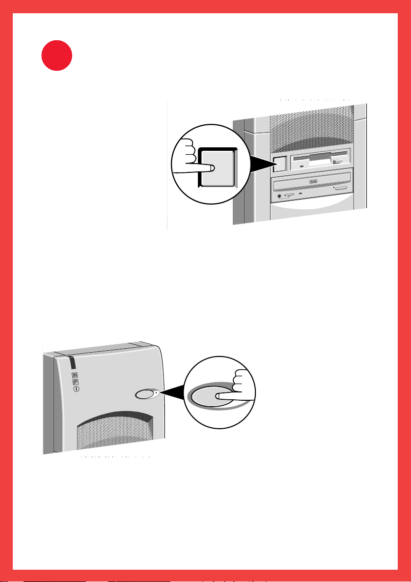
1
When you have fully
connected your system
press the Power button to
turn the computer on.
When the system unit
is powered the power
indicator on the left of
the front panel will light
up. If nothing happens,
check your connections and
supply switch.
Refer to the “Troubleshooting” chapter in the Owner’s Handbook if you
encounter any problems.
Remember that the monitor has its own power switch; see the monitor’s
User’s Guide for details.
The Standby button can be used to both place the system into an energy
Power Up
COMPACT
saving mode or restore it to
normal operation. Next
to this button is an
LED which lights
up during either of
the Energy Saving
modes. Further
details are provided
on the last page of this
guide.
The system will now perform a self-test routine and then display the message,
‘Starting Windows 95’. This will take several minutes the first time you
switch on, during which time the computer will reboot several times
and you will be requested to register your copy of Windows 95.
Page 4
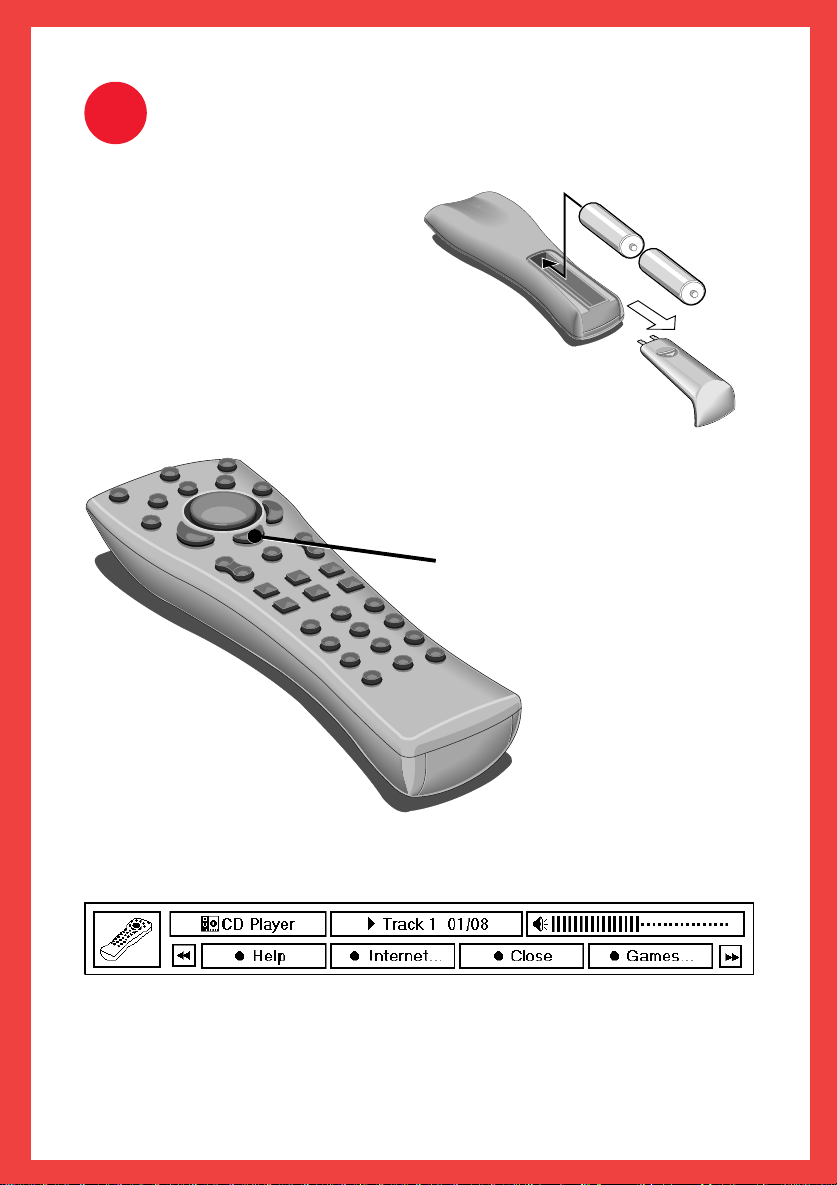
2
The Remote Control
The optional infra-red remote
control offers a friendly userinterface to the inexperienced user.
The remote control operates on two
AA batteries, which are provided.
You need to insert the batteries into the remote
control unit in order to use it. Use the diagram
opposite to insert the batteries.
The remote control has an integral two-button
mouse to control the major functions of the
multimedia applications.
Pressing the MENU button on the
remote control displays the
remote status window.
+
+
The remote status
window (shown below)
provides you with
information on the
current status of the
remote-controlled
program.
For example, here is the remote status window for the CD player:
Pressing the red button while this window is displayed provides access to
the remote control’s help file. To hide the remote status window, press the
MENU button on the remote control again.
Page 5
C
D
S
T
A
N
D
B
Y
M
E
S
S
A
G
E
T
V
C
A
N
C
E
L
O
K
E
X
I
T
T
A
S
K
MENU
VOL
REVEAL
ENLARGE HOLD
T TEXT
START
1
2
3
4
5
6
7
8
9
0
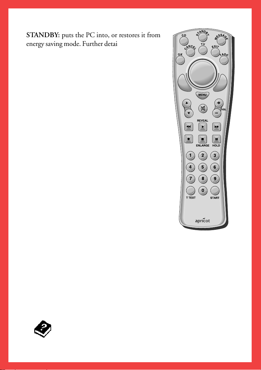
STANDBY: puts the PC into, or restores it from
energy saving mode. Further details on the energy
saving capabilities of your computer are provided
on the last page of this section.
If your computer has a TV card fitted, pressing
the TV button on the remote control for the
first time will activate the TV Wizard. This will
guide you through tuning into your local
transmitter.
MESSAGE: launches the Message Centre
application for accessing the various message types.
The Message LED on the front panel of the
computer will be lit when you have received any
new messages.
TTEXT: launches the TV application in full-screen
Teletext mode.
START: Displays the main menu to start a program,
find a file, or get help.
The coloured buttons can be used:
l In Teletext mode where they are used to drive
the Fasttext capabilities of the application.
l To control Apricot Easy Manager applications.
l Outside Apricot Easy Manager, the coloured buttons act as shortcuts
for common Windows actions. That is:
OK and CANCEL to accept/decline changes.
EXIT to close any application.
TASK changes focus between Windows applications. That is, it has
the same functionality as the Windows ALT-TAB command, which
switches between the windows you have opened.
Refer to the on-line tutorial, which can be found in the Apricot
Remote Control help file, for futher details.
Page 6
3
Playing Games
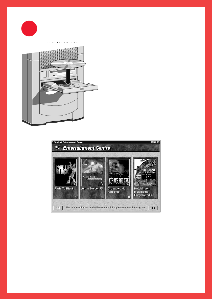
To play any of the games provided, you
need to insert the appropriate CD into
the CD-ROM drive. Press the button
on the front of the drive and place the
CD label-up on the platter.
Push the button again, or gently push
COMPACT
window. Then, press the corresponding
coloured button labelled ‘Games’ to load the
Entertainment Centre screen as shown below:
the front of the platter to draw it
back into the drive.
Using your remote control, press the
MENU button to display the status
You can select any of the games by clicking the labelled coloured button
with your mouse, or by pressing the appropriate coloured button on the
remote control. Some games will require the system to run in DOS-only
mode. Where this is the case Windows 95 will shut down and reboot in
DOS mode for the duration of the game. Remember to exit the game properly
and restore Windows 95 before you switch the system off.
The pictures of the software shown above are for example purposes only,
actual software may vary.
Page 7

4
This computer system is shipped with the latest Energy Star power-saving features
already activated, allowing you to be more environmentally friendly in your
work. It is intended to help reduce global power consumption, and ultimately
waste and pollution. This computer system is designed, when left unattended,
to enter a ‘Low Power’ mode followed by ‘Standby’ mode shortly afterwards.
LOW POWER MODE
In this state the screen will be blank but your software will still be running,
although it will run much slower.
You can Restore the system by moving the mouse, pressing any keyboard key, or
by pressing the purple STANDBY button on either the front panel, or the
remote control. The computer will quickly restore to the state in which you left
it. The monitor may take a few seconds to warm up again.
STANDBY MODE
In this state the monitor will be in a controlled ‘off ’ state. The system and
software will assume a frozen state. You will not lose any unsaved data, unless
your mains electricity supply fails. The system fans will slow down or stop
altogether.
Please remember...
You can Restore the system by pressing the purple STANDBY button on the
front panel of the system or the one on the remote control. The computer will
quickly restore to the state in which you left it. The monitor may take a few
seconds to warm up again.
NOTE
Pressing either of the STANDBY buttons when the system is in normal use will
put the system directly into standby mode.
You can change any of the above settings. How to
access the Apricot power Manager is shown in the
chapter ‘The multimedia applications’. Refer also to
the application’s help file.
Page 8

OWNER’S HANDBOOK
APRICOT MS660
Page 9

Intel, ‘Pentium®’ and ‘Pentium® with MMX
TM
technology’ are registered
trademarks of Intel Corporation.
Microsoft, MS-DOS, Windows
®
and Windows® 95 are registered trademarks of
Microsoft Corporation in the US and other countries.
Other trademarks mentioned within this document and not listed above are the
properties of their respective owners.
Information contained in this document is subject to change without notice and
does not represent a commitment on the part of Apricot Computers Limited.
Any software described in this manual is furnished under a license agreement.
The software may be used or copied only in accordance with the terms of this
agreement. It is against the law to copy any disk supplied for any purpose
other than the purchaser’s personal use.
No part of this manual may be reproduced or transmitted in any form or by any
means electronic or mechanical including photocopying and recording, for any
purpose, without the express written permission of the publishers.
Copyright © Apricot Computers Limited 1996. All rights reserved.
Published by:
Apricot Computers Limited
3500 Parkside
Birmingham Business Park
Birmingham, England
B37 7YS
http://www.apricot.co.uk
Printed in the United Kingdom
Page 10

CONTENTS
Safety and regulatory notices
General i
Standards ii
Power connection guidance iii
Power cable wiring UK ONLY iv
1 Introducing your computer
Your multimedia computer 1/1
Energy-efficient features 1/2
Pictorial guides 1/3
Removing panels 1/6
The internal layout 1/8
2 Using your computer
Using the 3.5 diskette drive 2/1
Using the CD-ROM drive 2/3
Using the (optional) PD drive 2/7
Cleaning your drives 2/9
The sound connections 2/10
The speaker sound system 2/12
Customising your display settings 2/13
The hard disk drives 2/14
Software backup 2/14
Using help 2/15
3 First use of Internet and ‘Branding’
Setting up your FREE Internet/Fax 3/1
‘Branding’ your computer
4 The multimedia applications
Media Manager application 4/1
Message Centre application 4/3
Entertainment application 4/4
Power Manager application 4/5
Internet Connection application 4/6
TV/Teletext application 4/7
CONTENTS 1
3/3
Page 11

5 Expansion cards
Configuring a card 5/2
Installing a card 5/6
6 System upgrades
System memory 6/2
Upgrading the processor 6/5
Second hard disk drive 6/8
New drives/accessories 6/10
7 Troubleshooting
Problems when starting 7/1
Restoring the software 7/5
Troubleshooting checklist 7/5
System disk drives 7/9
8 System motherboard
Principal features 8/1
Changing the jumper settings 8/2
System connectors 8/5
Replacing the CMOS battery 8/6
9 System BIOS and setup
Entering setup 9/2
Setup runs on its own 9/2
Control keys 9/3
Main menu screen 9/4
Error messages 9/13
Note down your BIOS settings 9/14
2 CONTENTS
Important information
Antistatic information A1
Cleaning and transporting A2
Fall-back password ‘
*read the instructions first ! See chapter 3
Cut-Out’ page
A3 *
Page 12

SAFETY AND REGULATORY NOTICES
Electrical
The computer uses a safety ground and must be earthed.
The system unit AC power cord is its ‘disconnect device’. Ensure that the
system unit is positioned close to the AC power outlet and that the plug is
easily accessible. The power cord packed with the computer complies with
the safety standards applicable in the country in which it is first sold. Use
only this power cord. Do not substitute a power cord from any other
equipment.
To prevent fire and electric shock, do not expose any part of the computer
to rain or moisture and turn off the computer and unplug all power cords
before moving or cleaning the system unit, or removing any system cover.
Battery
This product contains a lithium battery:
Do not use a metal or other conductive implement to remove the battery. If
a short-circuit is made between its positive and negative terminals the
battery may explode.
Replace a discharged configuration (CMOS) battery with one of the same
type. Dispose of the battery in accordance with the manufacturer's
recommended instructions and Do not attempt to recharge, disassemble or
incinerate the discharged battery. Keep away from children.
Laser products
Any CD-ROM drive fitted in this system is classified as a CLASS 1 LASER
PRODUCT according to IEC825 Radiation Safety of Laser Products
(Equipment Classification: Requirements and User's Guide). The CLASS 1
LASER PRODUCT label is located on the underside of the system unit.
Ergonomic
It will be in high visibility colours and bear the details shown above.
Use the CD-ROM drive only as described in this manual. Failure to do so
may result in exposure to hazardous radiation.
When positioning the system unit, monitor and keyboard, take into
account any local or national regulations relating to ergonomic
requirements.
SAFETY AND REGULATORY NOTICES
i
Page 13

External Speakers (where supplied)
Always switch off or disconnect the AC supply before disconnecting any of
the speaker leads, whether audio or power. Disconnect the AC supply
when equipment is not used for a period of time.
To prevent the risk of electric shock, do not remove speaker covers.
Connecting the speaker power cord to any other cords or joining cords
together can cause fire and risk of electric shock.
Standards
Safety
This product complies with the European safety standard EN60950 plus
amendments 1, 2, 3 and all European country deviations.
Electro-magnetic Compatibility (EMC)
This product complies with the following European EMC standards:
Emissions EN55022 Class B
Immunity EN50082 Level 2
This product also complies with the following International EMC standards:
VCCI level 2 (Japan)
German Acoustic Noise Regulation
Sound power level is less than 70 dB(A) according to DIN 45635 Part 19
(ISO 7779).
Notes
All interconnecting cables (e.g. Microphone, headphone and speaker) and
communication cables should be less than 2 metres in length. If cable
extensions are used, ensure adequate earth connections are provided and
screened cables are used.
Legalities
This equipment complies with the following European Directives:
Low Voltage Directive 73/23/EEC
EMC Directive 89/336/EEC
CE Marking Directive 93/68/EEC
and where applicable:
Telecommunications Directive 91/263/EEC
CautionCaution
This system complies with the CE marking directive and its strict legal
requirements. Use only Apricot tested and approved parts. Failure to do so may
result in invalidating both the compliance and your warranty. All expansion
cards or upgrade components must carry CE marking.
ii SAFETY AND REGULATORY NOTICES
Page 14

Thermalcote bonding compound
E
N
L
125V
The thermal bonding compound used between the system processor and its
heatsink can cause skin irritation and stain clothing. Avoid prolonged or
repeated contact with skin. Wash thoroughly with soap and water after
handling. Avoid contact with eyes and inhalation of fumes. Do not ingest.
Power connection information
Typical AC plugs
250V
E
L N
250V
E
N L
BS1363A SHUCO NEMA 5-15P SRAF 1962/DB16/87 ASE 1011
U. K. Austria Belgium Taiwan Denmark Switzerland
Finland France Thailand
Italy Germany Japan
Sweden Norway USA
Holland Canada
250V
L
N
E
250V
Procedure
NoteNote
Any ancillary equipment using an AC power supply cable should be earthed.
The power supplies in the computer and the monitor are correct for the
country in which the system is first sold. Do not alter any switch settings
on the rear of the system. If you wish to use the computer in another
country it may not be suitable, contact your supplier or an authorised
Apricot dealer.
♦ Before connecting up any parts of the system, ensure that the AC
supply is switched off or disconnected.
♦ First connect up the keyboard, mouse, monitor signal cable, and
audio cables as appropriate.
♦ Connect up all AC cables. (System to supply, system to monitor, all
related peripherals.) Then switch on or connect the AC supply.
♦ Switch on the monitor first, then the computer followed by the
peripherals, such as printer or speakers.
SAFETY AND REGULATORY NOTICES iii
Page 15

Power Cable Connections - UK ONLY
This equipment is supplied with an AC power lead that has a
moulded, non-removable, 3-pin AC plug.
Always replace the fuse with one of the same type and rating which
is BSI or ASTA approved to BS1362.
Always refit the fuse cover, never use the plug with the fuse cover
omitted.
Never substitute a power cord from any other appliance. If you
suspect a fault with the AC power lead, obtain a replacement from
your supplier or authorised maintainer.
iv SAFETY AND REGULATORY NOTICES
Page 16

1 INTRODUCING YOUR
COMPUTER
This chapter gives you a quick tour of your Apricot multimedia
computer. It details the various features of the computer and
contains pictorial guides to help you become familiar the various
parts of the machine.
If you have yet to get your computer up and running for the first
time, please refer to the ‘Quick Start Guide’.
WarningWarning
Read the power guidelines which can be found in the ‘Safety and
Regulatory Notices’ section of this manual before using the computer for
the first time.
Your Multimedia Computer
Your MS660 multimedia computer comes with a host of standard
features (listed below), as well as providing the opportunity of
expanding the system to suit your personal requirements.
Don’t worry if you are unfamiliar with some of the computer
terminology used here. It’s provided as a useful ‘shorthand’ for more
experienced readers. Be assured, you don’t need to understand any
jargon to use the computer safely and efficiently. On the other
hand, if you wish to learn more, introductory books about
computers can be found in your local bookshop or library.
Standard Features:
Intel
♦
8 Mbytes of random access memory (RAM), which is
♦
upgradeable
BIOS Setup configuration utility in read-only memory (ROM).
♦
Apricot’s Electronic Fingerprinting
♦
Full
♦
Pentium processor
to 128 Mbytes.
power management
processor with upgrade capability.
security
.
MS660 OWNER’S HANDBOOK 1/1
application.
Page 17

Introducing your computer
On-board high performance PCI bus video based on an ATI
♦
264GT controller, for
equipped with 2 Mbytes of video memory.
Primary and secondary local bus Integrated Drive Electronics
♦
AT-Attachment (IDE/ATA) interfaces for IDE hard disk
drives and ATA-PI (ATA Packet Interface) CD-ROM drives
respectively.
On-board Creative Labs
♦
Plug and Play functionality.
Six expansion card slots.
♦
1.44 Mbytes floppy diskette drive and fast hard disk drive.
♦
Powerful speakers.
♦
♦ Dual stacked Universal Serial Bus
link connectors to USB compatible interfaces, for future
expansion.
Optional features:
Apricot Sensonic anti-theft alarm system.
♦
Infra-red remote control, fully integrated two button mouse.
♦
TV with Teletext support and operation.
♦
16 Mbytes of memory.
♦
Wavetable card to bring realism to your digital sound system.
♦
Deep Sound subwoofer.
♦
enhanced 3-D graphics
Soundblaster 16
(USB) high-speed ‘serial’
audio which has
capabilities,
Energy-efficient features
All models in the range comply with the requirements of the US
Environmental Protection Agency’s ‘Energy Star’ programme for
energy-efficient computers. These models support:
System Management Mode (SMM) of processors.
♦
Operating systems and applications that use the
♦
Intel/Microsoft Advanced Power Management (APM)
interface standard.
1/2 MS660 OWNER’S HANDBOOK
Page 18

Introducing your computer
VESA BIOS Extensions for Power Management (VBE/PM),
♦
for use with energy-efficient monitors that support Display
Power Management Signalling (DPMS).
CautionCaution
Do not attempt to use the computer’s energy-saving features with a
monitor that does not support DPMS; the monitor may be permanently
damaged. If in doubt consult your supplier.
If the computer is left unattended for a certain amount of time
(defined in the Apricot Power Manager application) the computer
will enter a Low Power mode. The screen will blank, and some of the
computer’s components will slow down.
meant to happen.
Pressing any of the keys on the keyboard or moving the mouse will
restart the computer in full power mode. There is also a further
mode of Standby, for which the purple button is used to restore the
system. (See the following pictorial guides to locate this button). In
this mode, everything stops, but the system will respond to
incoming messages and scheduled events. All the settings can be
adjusted or disabled if required.
Do not worry!
This is
Further detailed information, on all of this, can be found in the help file
provided with the Apricot Power Manager application. How to find
the application is shown in the chapter ‘The Multimedia
applications’.
Pictorial guides
The following pages show details of the front, back and inside of the
system, along with instructions on how to remove the panels to gain
access to the inside components.
You should study them carefully and familiarise yourself with all the
connections and controls before reading some of the following
chapters as it will make them easier to understand.
MS660 OWNER’S HANDBOOK 1/3
Page 19
Introducing your computer
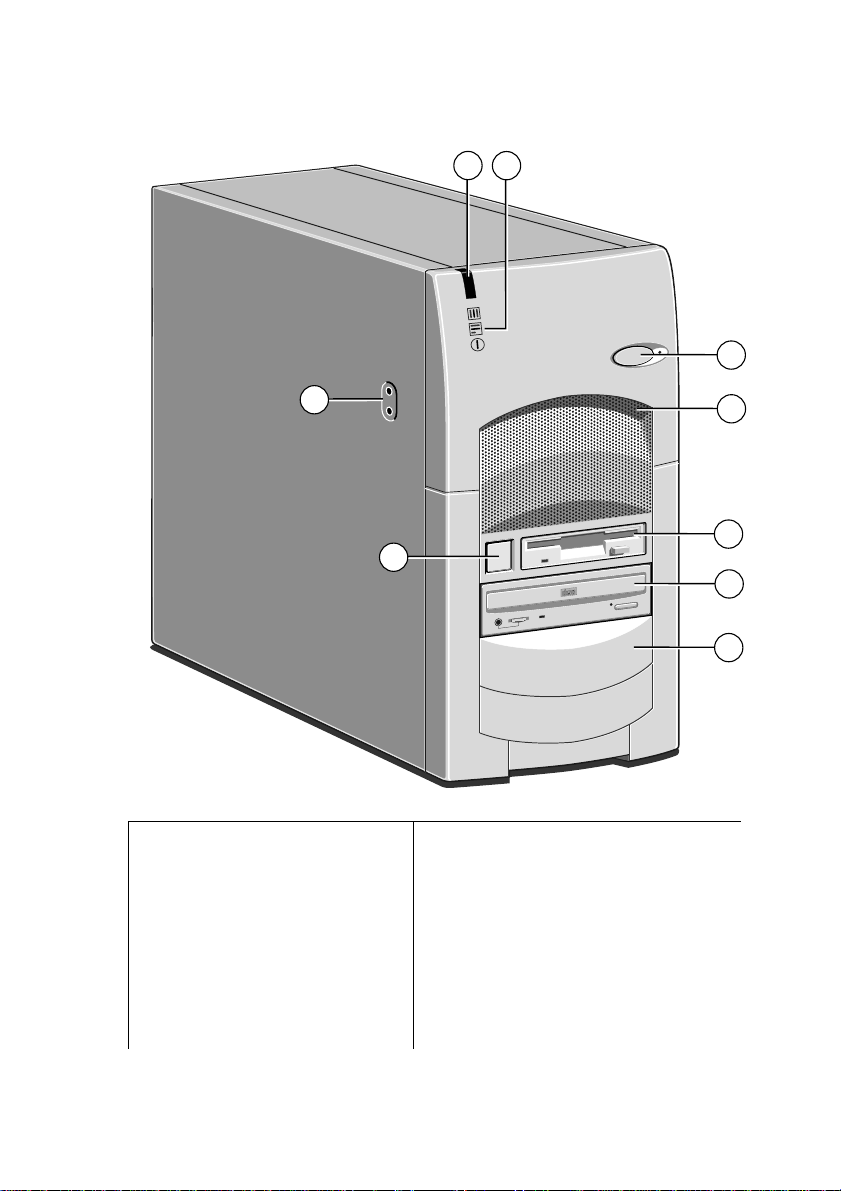
Front View
8
9
1
7
6
COMPACT
1 Energy saving button and LED 6 Power button
2 Internal speaker grill
(This speaker cuts off when
external speakers connected)
3 Floppy diskette drive 8 Receiver for optional remote control
45CD-ROM drive
-or optional PD drive
Available drive bays
7 Front audio connections:
Upper - Speakers
Lower - Microphone
9 System LEDs:
Upper - Message received
Middle - Hard disk active
Lower - AC power on
2
3
4
5
1/4 MS660 OWNER’S HANDBOOK
Page 20
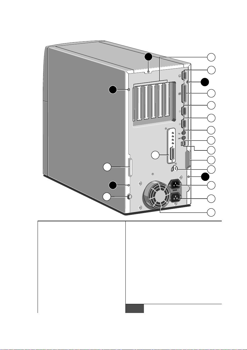
Rear View
Introducing your computer
A
1
2
A
A
3
4
1
10101
2
5
6
7
8
9
10
10
11
A
A
15
12
13
14
1 Rear of expansion bay 9 Audio (see chapter 2 for details)
2 VGA port for monitor signal
cable
3 Parallel or printer port 11 Security loop for cable or padlock
4 Serial port 2 (not useable if
remote control supplied)
5 Serial port 1 13 AC power input from supply
6 Port for PS/2 mouse 14 Protection cover for PSU fan
7 Port for PS/2 keyboard 15 Main side panel lock
8 Dual stacked USB port
10 Handles to assist during side panel
removal
12 AC power output for monitor
DO NOT use to lift system
Panel fixing screws
A
MS660 OWNER’S HANDBOOK 1/5
Page 21

Introducing your computer
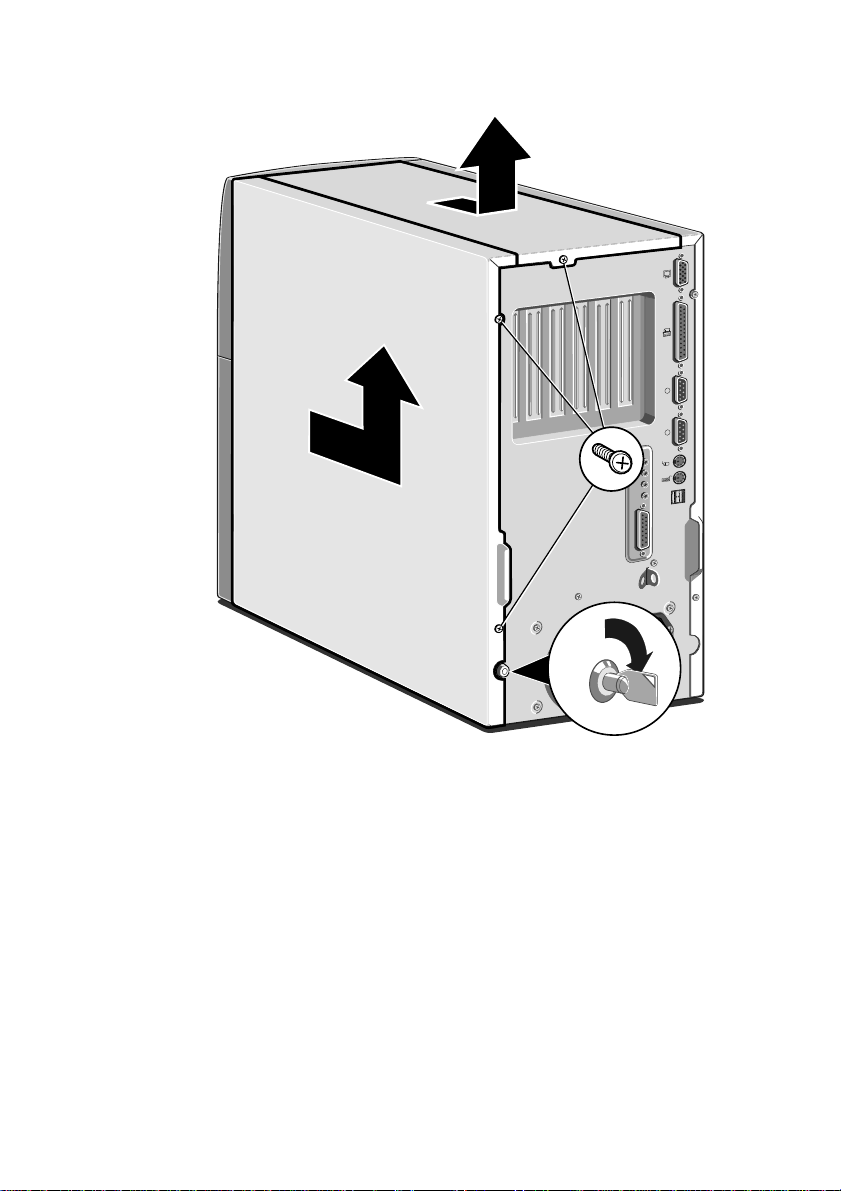
Removing panels
For complete access to the motherboard and for fitting expansion
boards the main side panel and the top panel both have to be
removed. Both side panels will require removal if any drives are to
be fitted into the remaining drive bays.
WarningWarning
Turn off the computer, along with all peripherals, and unplug all power
cords before removing any panels. Take suitable antistatic precautions
while any of the system panels have been removed.
Main panel
1. Unlock the cover with the special key provided. The lock is
shown on the drawing opposite.
2. Release the appropriate panel screws.
3. Slide the panel carefully towards the rear of the system using
the handle provided.
4. After about 2 to 3 cm movement it is possible to lift the panel
vertically clear of the system.
The lower half of the motherboard and all of its components are
now accessible. For complete access carry on and remove the top
panel.
CautionCaution
Exercise care with the removed panels as there are metal fixings and
hooks on the inside. These may scratch delicate surfaces.
Top panel
1. First remove the main side panel as detailed above.
2. Remove the top panel retaining screw.
3. Again slide the panel towards the rear of the system.
4. After 2 to 3 cm the panel should be free to lift off.
You can now safely access or fit expansion cards.
1/6 MS660 OWNER’S HANDBOOK
Page 22
Introducing your computer
1
10101
2
Other side panel
This panel only needs to be removed for access to the drive bay
fixing screws. No other components can be reached from this side.
1. Remove the two panel securing screws.
2. Slide the panel carefully towards the rear of the system using
the handle provided.
3. After about 2 to 3 cm movement it is possible to lift the panel
vertically clear of the system.
The access window to the drive mounting screws is now clearly
visible. For instructions on fitting drives see the chapter on
upgrading your system.
MS660 OWNER’S HANDBOOK 1/7
Page 23
Introducing your computer
1
4
5
9
10
7
6
8
3
2
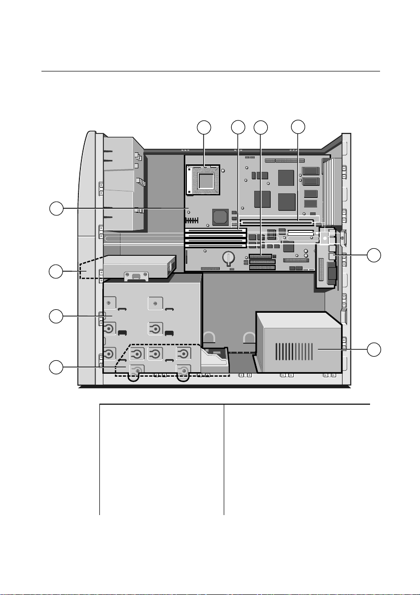
The internal layout
Please note that for clarity, all the internal ribbon and power
connections are not shown.
1 Power supply 6 Processor socket
2 First hard disk 7 Memory, banks 1 and 2
3 Main drive housing
-CD-ROM at top
4 Floppy diskette drive 9 Expansion riser
5 Motherboard:
(see Motherboard chapter
for details)
8 Connections for drive ribbon
cables
10 Audio board:
(see chapter 2 for connection
details)
1/8 MS660 OWNER’S HANDBOOK
Page 24

2 USING YOUR COMPUTER
You should read this chapter even if you do not read any other. It
provides useful information on the correct operation of the drives
fitted to your computer and explains the multimedia features.
This guide assumes that your computer is up and running. If you
have yet to get the computer up and running please refer to the
‘Quick Start Guide’ before you read any further.
Using the floppy diskette drive
The floppy disk drive is usually configured in the system BIOS as
drive A:, with a capacity of 1.44 Mbytes.
The floppy diskette drive can read and write to both 720 Kbytes
disks (if marked ‘DD’ or ‘double density’) and 1.44 Mbytes disks (if
marked ‘HD’ or ‘high density’). The HD disks have twice the capacity
of DD disks, it is therefore more economical to purchase them.
Each diskette has a rigid plastic cover with a metal shutter that
guards the disk surface. The drive automatically moves the shutter
aside to read the diskette.
CautionCaution
Never touch the exposed surface under the shutter; you could deform the
disk or leave a fingerprint that might make it difficult to read.
The immediate physical differences between the HD and DD
floppy disks are shown in the diagram below:
The HD disks have the ‘HD’ logo near the shutter and an extra
hole beside the label. This enables the drive to distinguish between
MS660 OWNER’S HANDBOOK 2/1
Page 25
Using your computer
COMPACT
the two. The other hole which exists on both disks is the write
protect tab (on the underside).
Keep diskettes well away from dust, moisture, magnetic objects, and
equipment that generates magnetic fields. Also, avoid extremes of
temperature and exposure to direct sunlight. Otherwise, data
recorded on the diskette may become corrupted.
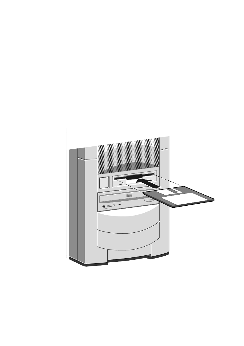
Inserting a diskette
A diskette is inserted into the diskette drive slot shutter-foremost,
and with its label side facing up. Some diskettes have a small arrow
on the face of the diskette; this must point towards the drive when
you insert the diskette:
Push the diskette all the way in until it engages with the drive
mechanism. When the drive’s eject
fully engaged.
2/2 MS660 OWNER’S HANDBOOK
button pops out, the diskette is
Page 26
Removing a diskette
Before attempting to remove a diskette, make sure that the drive is
not currently in use (the diskette activity indicator, opposite the
drive’s eject
button must be unlit). Press the eject button on the
drive. The drive mechanism disengages and the diskette is ejected
half-way out of the drive.
If a diskette becomes stuck in the drive, perhaps because its label has
peeled back, do
similar implement; you risk damaging the drive. Call an authorised
maintainer.
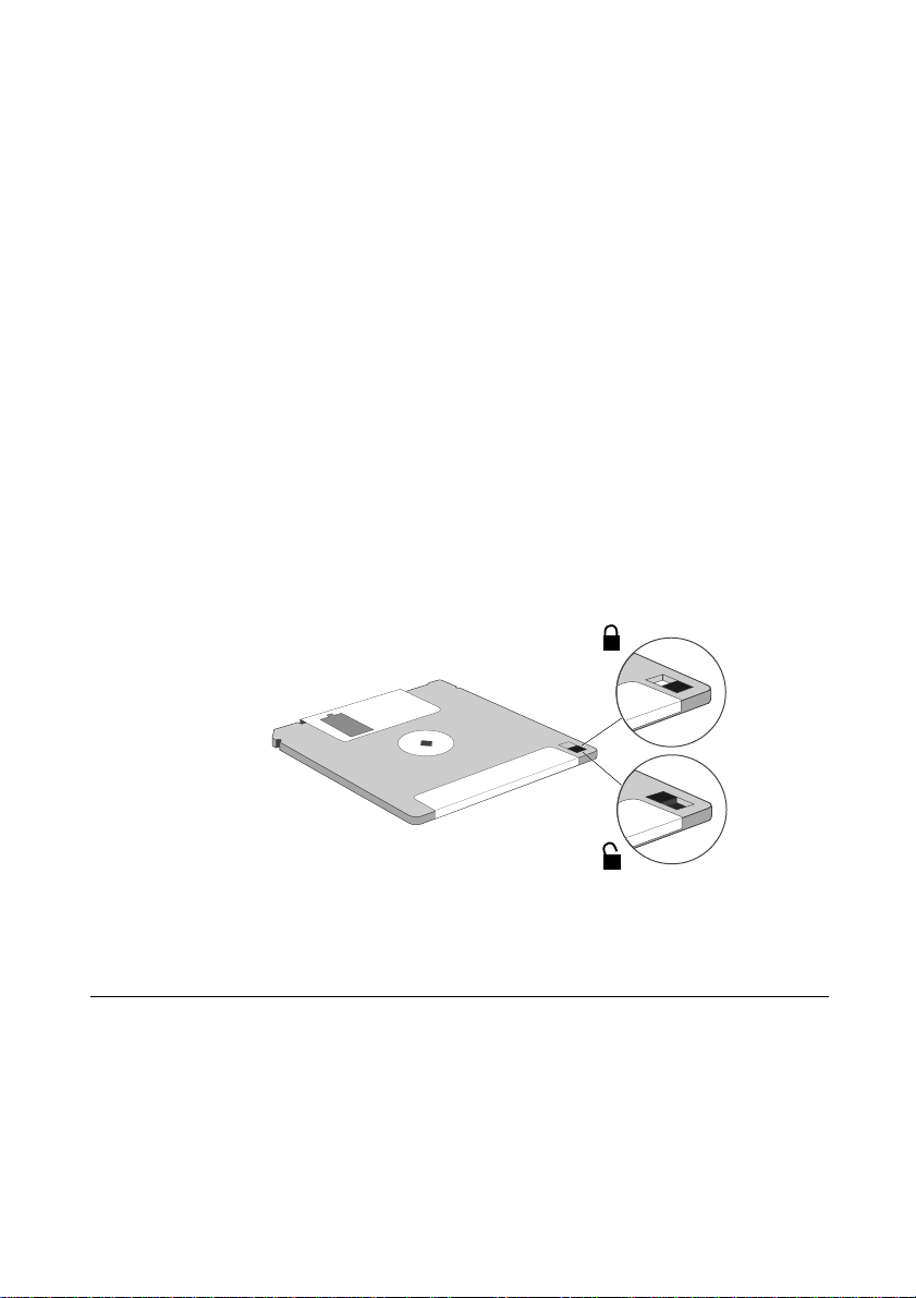
Write-protecting a diskette
A diskette can be write-protected by sliding a small tab towards the
edge of the diskette to expose the little hole beneath it (see
diagram). With the tab in this position, you can read, copy or print
files from the diskette, but you cannot create, rename or delete any
files.
Using your computer
attempt to remove it with tweezers or any
not
The BIOS Setup utility can be used to bar access to the diskette
drive. See ‘System BIOS and Setup’ for further details.
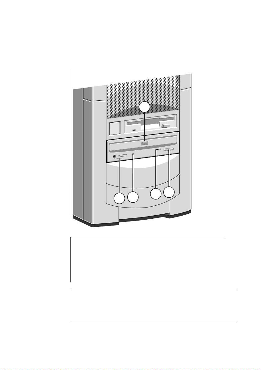
Using the CD-ROM drive
The CD-ROM drive can retrieve multimedia data from CD-ROM
discs and multi-session Photo-CD discs. It can also play commercial
audio CDs.
It is important that the computer is not moved while a CD is in the
drive, especially if the CD is being played at the time.
MS660 OWNER’S HANDBOOK 2/3
Page 27
Using your computer
COMPACT
2
3
4
5
1
The CD-ROM LED flashes when the CD-ROM tray is opened,
and when it is active (i.e. busy reading information).
The CD-ROM drive has the following features:
1 Disc drawer
2 Headphone jack and headphone volume level
3 Busy indicator
4 Emergency eject hole
5 Eject button
WarningWarning
The laser beam inside the CD-ROM drive is harmful to the eyes. Do
not attempt to disassemble the CD-ROM drive. If a fault should occur
it is advisable to contact an authorised maintainer.
2/4 MS660 OWNER’S HANDBOOK
Page 28
The headphone socket and volume control can be used whilst
COMPACT
listening to commercial audio or music CDs (providing you are not
using external speakers, or feeding the output to your hi-fi). You can
still use all the other various features of your computer whilst you
are playing an audio CD.
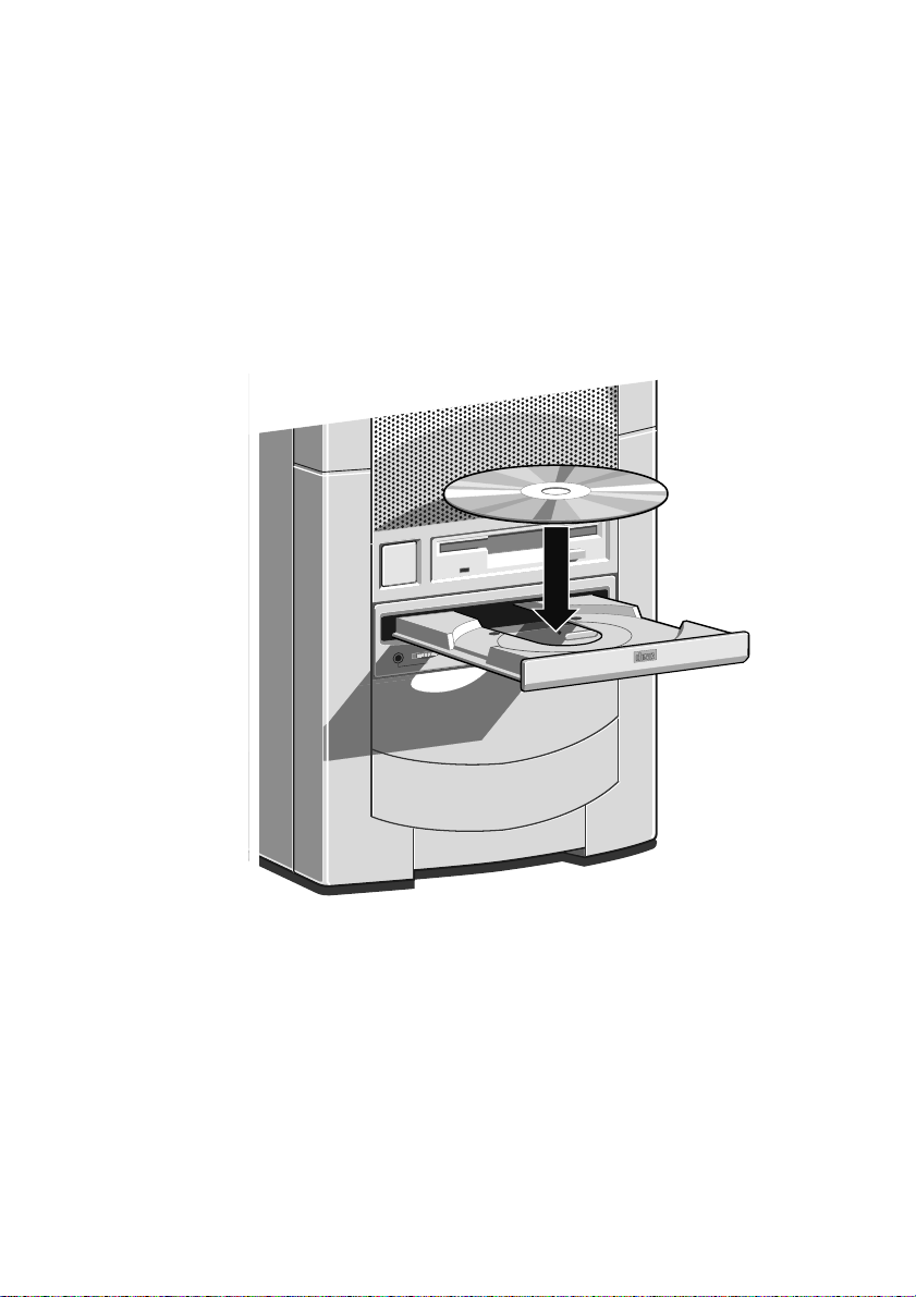
Inserting a compact disc
Using your computer
Press the
button on the front of the drive and place the CD label up
on the platter:
Push the button again, or gently push the front of the platter to
draw it back into the drive.
Removing a compact disc
Before attempting to remove a CD, ensure that the drive is not
currently active.
Press the Eject button. The drive mechanism disengages and the
platter is ejected.
MS660 OWNER’S HANDBOOK 2/5
Page 29
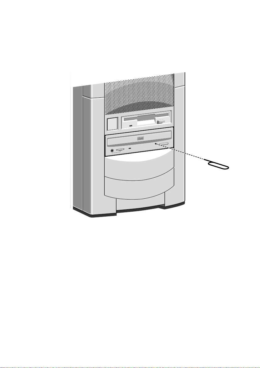
Using your computer
COMPACT
To eject the drawer manually (for example, during a power failure)
you must ensure that the computer is turned off. Then insert a thin
metal rod (such as an unwound paper clip) into the emergency eject
hole and push, see below:
Care of CDs
Keep CDs well away from dust and moisture, and avoid touching
the surface of the CD. Avoid extremes of temperature and exposure
to direct sunlight as these may cause the disk to warp.
Always store CDs in there original cases wherever possible.
Replacement cases are readily available in the larger record stores.
CD storage racks are useful as you will find the majority of new
software is now supplied in CD format.
2/6 MS660 OWNER’S HANDBOOK
Page 30
Using your computer
COMPACT
3
5
7
PD/CD
BUSY
6
4
2
1
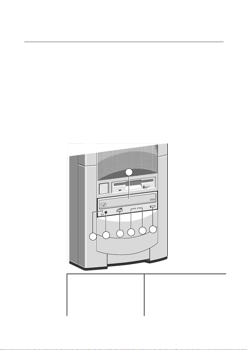
Using the (optional) PD/CD-ROM drive
The dual purpose PD/CD drive can read CD-ROM, Photo CD and
play audio CDs as well as providing re-writable optical cartridge
backup. It can be fitted as an option into any system where both a
CD-ROM drive and an efficient re-writable backup device is needed.
The Phase-change drive will occupy the same space as the
conventional CD-ROM drive, with the minor differences in
controls as shown in the illustration.
The drive control software provides two icons in both the drives
control panel and the Windows 95 explorer. Each has its own drive
letter representing either the PD data cartridge, or the CD-ROM. If
you click on the wrong one, (and try to access the wrong media) the
software will give you a simple error message.
1 Disk/cartridge drawer 5 Media Indicator LED
2 Emergency eject hole 6 Drive busy indicator LED
3 Stereo headphone socket 7 Eject button
4 Volume control for
headphone
MS660 OWNER’S HANDBOOK 2/7
Page 31

Using your computer
PD/CD
BUSY
Inserting a PD cartridge/ compact disc
WarningWarning
The PD/CD drive can only accept one type of disk at any one time. Do
not try to attempt to load both a CD and PD cartridge at the same time
as this will severely damage the drive.
Press the Eject button on the front of the drive and place the CD or
PD cartridge face up on the platter:
Push the button again, or gently push the front of the platter to
draw it back into the drive.
The indicator LED will then light up to indicate the type of disk
which has been inserted. The indicator shows green when the drive
detects a CD-ROM but changes to amber when a PD cartridge is
inserted.
The drive busy indicator will flash for a short while as the drive
spins up to speed. Wait until it stops flashing before attempting to
read or write information form it.
The drive can use any PD cartridges bearing the
cartridge is not formatted you will be prompted to format it. All the
standard types of CD can be used in this drive, data, music etc.,
including the mini-CD.
2/8 MS660 OWNER’S HANDBOOK
logo. If the
Page 32

Removing a PD cartridge/compact disc
Before attempting to remove a CD or PD cartridge from the drive,
ensure that the drive is not currently active (wait for the drive’s busy
activity indicator to stop flashing).
Press the Eject button. The drive mechanism disengages and the
platter is ejected.
To eject the drawer manually (for example, during a power failure)
you must ensure that the computer is turned off. Then insert a thin
metal rod (such as a unwound paper clip) into the emergency eject
hole and push (as shown for emergency eject of the CD-ROM
drive).
Write-protecting a PD cartridge
A PD cartridge can be write-protected by sliding the red switch (you
will need to use a pen or pencil tip) on the cartridge to the locked
position (marked with a closed padlock symbol) as shown below:
Using your computer
Cleaning your drives
Cleaning a floppy drive
Do not insert cotton buds or other implements into the drive door.
If you think the drive needs cleaning, obtain a specialist cleaning kit
from a reputable supplier. It looks like a floppy disk, but has a
special head cleaning surface inside which removes dust and fluff
from the reading heads and the mechanism. They should be used
only once and then discarded.
MS660 OWNER’S HANDBOOK 2/9
Page 33

Using your computer
Cleaning the CD-ROM or PD drive
It is recommended that you occasionally use a specialist CD
cleaning disk to clean the lens in the drive as it may become dusty
and fail to operate. Similar rules apply as for the floppy drive.
The sound connections
There is an audio interface board mounted at the rear of the system
providing a range of connections and interfaces to other equipment.
1
2
3
4
5
10101
2
1 Speaker connection 4 Microphone input
2 Line out (to Hi-Fi) 5 MIDI or joystick port
3 Line in (from Hi-Fi etc.)
The Joystick/MIDI port can be used to connect any analogue joystick
with a 15-pin D-sub connector, or Musical Interface Digital Interface
(MIDI) compatible device such as a music keyboard.
The mono microphone input is provided with phantom power for
electret condenser microphones. The minimum impedance of any
microphone used must be 8 Ohms.
NoteNote
Using either the microphone socket provided at the front of the machine
or the one provided with the rear audio board, disables the use of the
other, that is, only one microphone socket can be used at any one time.
2/10 MS660 OWNER’S HANDBOOK
Page 34

Audio inputs
1
10101
2
Using your computer
The line-in socket allows the connection of audio sources to be used
when monitoring or recording sound. You can connect a personal
stereo (tape or CD), or a line-out signal from a high-fidelity tape
deck or CD player.
Audio outputs
The line-out socket allows you to connect the audio output to the
line-in connections of a high-fidelity amplifier or tape deck.
10101
2
MS660 OWNER’S HANDBOOK 2/11
Page 35

Using your computer
1
10101
2
2-12
AC
1
10101
2
2-13
The speaker sound system
Your system comes with either separately powered speakers, or
standard speakers plus a Deep Sound subwoofer unit as an optional extra.
It is important that the power cord is connected last. Make sure the
AC power is off when connecting either power or audio leads.
The speaker cable which fits into the rear of the computer, plugs
directly into the speaker socket of the rear audio board and in doing
so, disconnects the internal speaker.
If you intend to use another speaker system, ensure that the speaker
impedance is 8 Ohm minimum.
Separately powered speakers only
Standard speakers only
2/12 MS660 OWNER’S HANDBOOK
Page 36

Using your computer
Standard speakers and Deep Sound subwoofer unit
1
10101
2
AC
Customising your display settings
Your copy of Windows 95 is initially supplied set up for a standard
VGA monitor, so that Windows 95 is sure to display correctly
whichever monitor you connect. However, all Apricot monitors can
display in higher resolutions than standard VGA.
When you have finished installing Windows 95, you can change the
setting to one that matches more closely to your own monitor, so as
to get the best performance from it.
Changing the monitor setting is done via the
‘Control panel’
menu route, then choosing the ‘display’ icon. It
‘Start’, ‘Settings’,
contains a list of major monitor manufacturers and models,
including all current Apricot monitors. You can also access this
setup by right clicking the mouse on the background of the
windows95 desktop and selecting ‘Properties’. See Windows 95
Help for more details on changing hardware settings.
MS660 OWNER’S HANDBOOK 2/13
Page 37

Using your computer
The hard disk drive
Apricot computers are supplied with one internal hard disk drive
which is divided into two partitions. They are designated as drives
and
C:
The Windows 95 programs and utilities can be found in the
C:\WINDOWS
95 User’s Guide and Help. Information on software tools, such as
one to compress the software into a smaller space or one to
defragment your files and make them faster to access can also be
found there.
DriveSpace
It is possible, as an alternative to the expense of fitting an additional
hard drive, to use the disk utility software such as
within Windows 95, which appears to increase and often more than
double the size of the hard disk drive using software compression
technology. It is advisable to backup your data before you do so. Refer
to the Windows 95 Help files for further details on this utility.
in the Windows 95 Explorer software.
D:
Software Backup
folder. More details can be found in the Windows
DriveSpace
Apricot computers normally arrive with the operating system preinstalled on the hard disk. The hard disk also contains a complete
set of ATI video display drivers. Additional software may be preinstalled by your supplier.
Apricot recommends that you copy or
software soon after setting up the system. This is particularly
important for systems which are supplied without installation
diskettes for the software on the hard disk. A back up copy will
safeguard the pre-installed software against loss if the hard disk fails,
or if you accidentally overwrite, or delete the files.
The Recovery CD (UK only) with your system contains all
♦ ♦
software including the operating system which was preinstalled at the factory. This CD can therefore return the hard
disk back to the way it was when it left the factory. Please refer
to the Recovery CD Instruction Card
2/14 MS660 OWNER’S HANDBOOK
back up
any pre-installed
before using the CD.
Page 38

Using Help
Using your computer
WarningWarning
The Recovery CD will return your hard disk back to way it was when it
left the factory. Please ensure whenever possible that you have separately
backed up data files as any software installed since your first power on,
or data created since then will be lost during the recovery procedure.
Microsoft’s Create System Disks utility provided within
♦
Windows 95, in the System Tools folder can be used to make
master floppy disks of any other pre-installed software
provided with your system.
NoteNote
Any copy you make of pre-installed software must be used
up copy, in case the pre-installed software is lost. You are not allowed to
use installation diskettes created from disk images to install the software
onto another computer.
Along with the software pre-installed on your computer’s hard disk,
you will often find one or more Apricot Help files. These will
explain any special features of the system, and will tell you how to
install the software needed to exploit those features.
only
as a back
Apricot Help may be supplied as Windows Help files or README
text files. The Help Files will be found in the Apricot Folder. The
README.1ST files or other ASCII text files (identified by their
.TXT extensions) can be opened by most text editors and wordprocessing packages. Alternatively they can be displayed, one
screenful at a time, in a DOS window, using the command
For example:
More
more readme.1st
MS660 OWNER’S HANDBOOK 2/15
.
Page 39

3 FIRST USE OF INTERNET
AND ‘BRANDING’
Setting up your free Internet/Fax
To set up your free Internet and Fax (available in the UK only,
please check with the ‘Free Internet’ card) you need to complete the
following steps:
Double-click on the following icon on your desktop:
The following setup screen will appear:
1
2
3
4
1. Your name should appear (you entered it to register for
Windows 95). If it does not, please type in your name.
2. Type in your Infotrade Account Number. This can be found
on the Free Access leaflet provided with your system.
3. Type in the telephone number your PC is connected to.
4. Press the
you have entered will appear on the following screen:
Setup Now
button to continue and the information
MS660 OWNER’S HANDBOOK 3/1
Page 40

Internet and security
5. Check that the information is correct. If it is not, press the
Information
correct press the
button to correct the details. If the information is
Information is correct
button to continue.
6. The following screen appears when you press the
is correct
7. Press the
button:
Finish Setup
button. You have successfully
Re-enter
Information
completed setup.
For normal use of the Internet and connecting to it, you should
now turn to chapter 4 for further information.
3/2 MS660 OWNER’S HANDBOOK
Page 41

‘Branding’ your computer
Internet and security
‘Branding’ or
stored in part of the computer’s permanent memory. It is easily
done using the Apricot Electronic Fingerprinting application, which
will start up when the computer has finished setting up Windows
95. The application will open every time you switch on, until you
enter your personal details. These details will be displayed every
time the computer is switched on. It is intended that this
information includes your name, address and phone number so that
should your computer be stolen, it can be traced back to you.
fingerprinting
allows personalised information to be
Extremely importantExtremely important
The first time you use the Electronic Fingerprinting application a
1.
unique ‘fall-back’ password will be displayed. This is a 12-digit
number and can be used, in an emergency, if you should forget your
password.
the only time you will ever see it. A page at the back of the manual
is provided for you to note it down.
You must therefore make a note of this number
Cut it out and keep it in a
, this is
safe place.
2. If you have not yet ‘branded’ your computer it is advisable that you
do so before somebody else gains access to your computer and sets a
branding message and password which could then prevent you
having access to your own computer.
MS660 OWNER’S HANDBOOK 3/3
Page 42

Internet and security
NoteNote
You will be able to change any of the items in your branding details by
running the Apricot Electronic Fingerprinting application later and
entering the correct password. This would be necessary, for example, if
you moved house.
After you have entered your details you will be prompted to set a
password. This prevents anybody else from gaining access to your
personal details or changing them. Optionally, for extra security
Electronic Fingerprinting can be set such that this same password is
requested every time the computer is switched on.
When you have entered all the details and any chosen passwords,
the final step is to select ‘OK’. The information now has to be
written to the read only memory built onto the motherboard. This
will take a few moments and a message saying this will appear. Do
not switch off while this is going on.
Until you have entered your branding details, the Apricot Electronic
Fingerprinting application will automatically run each time
Window 95 starts. Thereafter, the program can be run by selecting
its icon which is displayed at the top of the Start bar menu. You will
be asked to enter your password.
Please refer to the on-line help file for detailed information.
CautionCaution
If you set a
Power On Password
effective and must be entered. It will be requested immediately
the fingerprint password has been verified.
3/4 MS660 OWNER’S HANDBOOK
in the system BIOS, this will still be
AFTER
Page 43

4 THE MULTIMEDIA
January
`97
3
?
?
side1
T
h
e
V
e
r
y
b
e
s
t
o
f
9
0
s
I
n
d
i
e
M
u
s
i
c
APPLICATIONS
This chapter details instructions on how to access the software
which comes with your computer. The Apricot group of
multimedia software applications are collectively referred to as the
Easy Manager Software.
The Apricot Media Manager application
The Apricot Media Manager application provides an easy way to
schedule the automatic launch of other software such as the TV,
CD applications. In addition the Media Manager allows you to create
automatic pop-up reminders and launch third-party applications.
Scheduling an event is easy with the user-friendly interface:
The current day is highlighted by default with the number shown in
red.
Any other day is easily selected by clicking on the day with your
mouse, which subsequently becomes highlighted (as 12th January,
shown above). You can press the day tab button on the monthly
view, double-click the selected day, or press the corresponding
MS660 OWNER’S HANDBOOK 4/1
Page 44

The multimedia applications
?
?
side1
T
h
e
V
e
r
y
b
e
s
t
o
f
9
0
s
I
n
d
i
e
M
u
s
i
c
3
?
?
side1
T
h
e
V
e
r
y
b
e
s
t
o
f
9
0
s
I
n
d
i
e
M
u
s
i
c
coloured button on the remote control to take you into the daily
view display:
To schedule an event for any time of the day select the icon
corresponding to the event you wish to schedule.
For example, to schedule the launch of the TV application to
coincide with the beginning of the Nine O’clock News you would:
1. Select the TV icon from the top of the Daily View. This will
then display the TV dialog.
2. You will be prompted to enter the start and end times for the
event, this being 21:00 and 21:30 respectively.
3. The default display mode is set to full screen. If you wish to
alter the display mode then select the ‘Display’ tab to select
your display mode preference.
4. Select ‘BBC 1’ in the ‘Channels’ tab.
5. Select the ‘Repeat’ tab to schedule the event for the week.
6. Finally, assign a title such as, ‘The Nine O’clock News’ to the
event. This helps you identify the event before it is about to be
launched as the title will appear in the taskbar countdown.
Further detailed information can be found in the on-line help file.
4/2 MS660 OWNER’S HANDBOOK
Page 45

The multimedia applications
The Apricot Message Centre application
The Apricot Message Centre application monitors your incoming
messages from the e-mail, fax or telephone systems.
The Message Centre LED on the front panel of the machine will
flash indicating that you have received a message in the Message
Centre. To find out what message has been sent, press the
MESSAGES
window with artistic views of the four message types that can be
accessed via the Message Centre (shown below).
A specific message type can then be selected by either pressing one
of the coloured buttons on the remote control corresponding to the
message types, or by pressing the message type button. This will
then open the specific message type window enabling you to access
the messages.
Apricot Message Centre
button on the remote control. This will open a single
Message Centre - Contents
Message Centre - Contents
Help
Help
Electronic Mail
?
?
Memo
0
0
MS660 OWNER’S HANDBOOK 4/3
FAX
Voice Message
10
5
Page 46

The multimedia applications
The Apricot Entertainment Centre application
The Apricot Entertainment Centre provides you with an interface
to the games and multimedia programs which came with your
system.
To access the Entertainment Centre press the
button on the
HELP
remote control, and then press the coloured button labelled
‘Games’. Providing the games CD has been inserted into the CDROM drive, pressing any one of the coloured buttons on the remote
control will load that particular game.
Some games will require the system to run in DOS-only mode.
Where this is the case Windows 95 will shut down and switch to
DOS mode while you are running the game. There is no need to be
concerned, as this is meant to happen. When you exit the game,
Windows 95 will be restored.
The pictures of the software shown in the above example may vary
with the software you actually receive.
4/4 MS660 OWNER’S HANDBOOK
Page 47

The multimedia applications
The Apricot Power Manager application
Intelligent power management features come as standard with your
system. These features allow you to leave your system powered 24
hours a day much like your video recorder.
The system will power down into a ‘standby’ state if it has been left
idle for 15 minutes (default setting) or by pressing the purple standby
button on either the front panel of the system or the remote
control.
As you become more familiar with your system you may wish to
change some of the actions of your system. It is advisable that
inexperienced users
cause incorrect components to power down whilst using certain
applications.
The Power Manager application is accessed by double-clicking the
following icon in the Windows 95 taskbar:
It will launch the power manager application:
attempt to alter any settings as you may
do not
Please refer to the on-line help file for further details.
MS660 OWNER’S HANDBOOK 4/5
Page 48

The multimedia applications
The Apricot Internet Connection application
Make sure your modem is connected, as shown on the ‘Apricot
Welcome Mat’.
The Apricot Internet Connection application provides you with the
ability to download the latest release of the Easy Manager software,
and establish connection to the Apricot Web server.
The download service compares the software files on your current
system with those held on the Apricot server. If there are outdated
you will be provided with the opportunity of updating them. This
facility allows you to obtain the latest software, and also restore the
software if it is corrupted. The system will need to be rebooted in
order for the downloaded files to take effect.
Connection to the Apricot web home page is made via Microsoft’s
Internet Explorer, and access to any World Wide Web (WWW)
pages can be made thereafter.
Closing (or terminating) the Apricot Internet Connection will
subsequently close Microsoft Internet Explorer. You will also be
requested at this point whether you wish to disconnect the modem
link. It is advisable to do so to ensure the proper release of your
telephone line.
There is an on-line help file available with the application if more
information is required.
If you are experiencing problems with your modem connection then
refer to the ‘Troubleshooting’ chapter of this manual for details.
4/6 MS660 OWNER’S HANDBOOK
Page 49

The multimedia applications
The Apricot TV/Teletext application (Optional)
CautionCaution
Before using the TV/Teletext application, with its setup Wizard, ensure
that you have a good and reliable aerial connection.
The Apricot TV/Teletext application provides full TV with integrated
Teletext support. You can access the TV application by pressing the
button on the remote control. Pressing this button for the first
TV
time activates the TV Wizard, shown below:
TV Wizard
Television
The TV Wizard will automatically tune into your local channels
and set the correct channel names, numbers and Teletext pages.
Once complete, the TV will start up in full screen mode.
Pressing the
button on the remote control will toggle the TV
TV
application between its various display modes: full screen, window,
and backdrop.
Pressing the right mouse button anywhere on the TV application
causes a pop-up menu to appear allowing you to adjust various
settings.
Please refer to the on-line help file for further details.
MS660 OWNER’S HANDBOOK 4/7
Page 50

5 EXPANSION CARDS
This chapter contains instructions on installing expansion cards in
your computer. It is important that you read this chapter before
purchasing a card.
If, having read the installation instructions, you do not feel
confident about installing the upgrade yourself you may wish your
supplier or service organisation to fit the card for you.
The only tool required is a small cross-head screwdriver.
WarningWarning
Never carry out any work on the equipment with power applied. Always
switch off at the mains and remove the power lead from the equipment
before starting work.
Your computer can accept various expansion cards or boards. Most
are simple to install with the benefit of the ‘Plug and Play’ features,
explained in the guide to Windows 95. (Look out for the ‘Plug and
Play’ (PnP) symbol on the packaging of these add-in boards.) You
can extend the capabilities of your computer, for example:
A graphics/movie card can provide more specialised video
♦
functions.
A television card can enable you to watch TV on your monitor
♦
and capture individual frames.
A network card can connect you to a Local Area Network
♦
(LAN) or a Wide Area Network (WAN)
CautionCaution
This system complies with the CE marking directive and its strict legal
requirements. Use only Apricot tested and approved parts. Failure to do
so may result in invalidating both the compliance and your warranty.
All expansion cards or upgrade components must carry CE marking.
Configuring the card
The Plug and Play (PnP) feature of ‘Peripheral Component
Interface’ (PCI) cards allows Windows 95 (and other PnP-aware
MS660 OWNER’S HANDBOOK 5/1
Page 51

Expansion cards
operating systems) to configure the card automatically when you
turn on the computer.
You need to use the
Control Panel
) in order to configure the card if Windows 95 does
Add New Hardware
utility (which is located in
not auto-detect it. Full instructions are provided on-line.
The documentation accompanying the card should tell you what is
required. Remember to check any diskettes supplied with the card
for README or other help files,
you start. If you are in any
before
doubt consult the supplier or manufacturer.
If manual configuration is required, usually with ‘Industry Standard
Architecture’ (ISA) cards, then you will probably need to specify at
least two of the following:
Interrupt request level (IRQ)
♦
Direct memory access (DMA) channel
♦
Base input/output (I/O) port address
♦
Base memory address
♦
The important thing to understand is that the settings used by the
card
be different from the settings used by the other hardware
must
in the computer, whether another card or a component on the
motherboard, the settings must not
conflict.
Some settings are done by jumpers and/or switches on the card and
are best done
installation, others are configured by running
before
installation software after installation. Some cards use a mixture of
both methods.
Cards often come with pre-configured or default settings. It is best
to rely on these settings as much as possible, and change them only
if they conflict with other devices.
ISA Interrupt request level (IRQ)
The interrupt request level or IRQ (the two terms are used
interchangeably) is the line over which the expansion card sends a
signal to get the attention of, or interrupt, the processor. Many of
these are reserved for components on the computer’s motherboard.
5/2 MS660 OWNER’S HANDBOOK
Page 52

Expansion cards
Some of these interrupts are fixed, others can be re-assigned, or
freed by disabling the component with BIOS Setup.
The following table lists the interrupts used by the computer and
shows which may be available for use by expansion cards.
IRQ Default assignment Available?
IRQ0 System timer No
IRQ1 Keyboard controller No
IRQ2 System No
IRQ3 Serial port 2 Optionally
IRQ4 Serial port 1 Optionally
IRQ5 Audio No
IRQ6 Diskette controller No
IRQ7 Parallel port Optionally
IRQ8 Real time clock No
IRQ9 Yes
IRQ10 Yes
IRQ11 Yes
IRQ12 Mouse No
IRQ13 Coprocessor No
IRQ14 Primary ATA/IDE interface No
IRQ15 Secondary ATA/IDE interface No
NoteNote
If you disable the interrupt which has been assigned to serial port 2 you
will disable the IR sensor used for the optional infra-red remote control.
IRQ3 is available if you disable serial port 2 with the BIOS Setup utility.
IRQ4 is available if you disable serial port 1.
disable either one unless you have no intention of using the
Do not
affected port. Similarly, if you have no intention of using the
parallel port, you can disable it with the BIOS Setup utility,
completely freeing IRQ7 for use by an expansion card.
MS660 OWNER’S HANDBOOK 5/3
Page 53

Expansion cards
Direct memory access (DMA) channel
Some hardware devices can use a DMA channel to access system
memory without directly burdening the processor. Computers have
DMA channels numbered DMA0 to DMA7. The following table
gives details of which ones may be available.
DMA Default assignment Available?
DMA0 Yes
DMA1 8-bit Audio Optionally
DMA2 Diskette/floppy disk controller No
DMA3 Enhanced Capabilities Port (default) Optionally
DMA4 System No
DMA5 16-bit Audio No
DMA6 Yes
DMA7 Yes
Base input/output (I/O) port address
I/O ports are used by the processor to communicate with hardware
devices. Some expansion cards are also controlled by I/O ports. The
base I/O port address specifies where the card’s ports begin. The
following table lists the I/O ports used by devices on the
motherboard. Any ports not listed below may be available for an
expansion card. This extensive list continues on the next page.
I/O ports Default assignment
000h-01Fh DMA controller 1
020h-021h Interrupt controller 1
034h, 038h, 03Ch Alternate Local bus ATA/IDE
040h-05Fh System timer
060h-06Fh Keyboard controller
070h-07Fh Real-time clock, NMI mask
080h-09Fh DMA page register
0A0h-0A1h Interrupt controller 2
0B4h, 0B8h, 0BCh Local bus ATA/IDE
5/4 MS660 OWNER’S HANDBOOK
Page 54

Expansion cards
I/O ports Default assignment
0C0h-0DFh DMA controller 2
0F0h, 0F1h Math coprocessor busy (clear/reset)
0F8h-0FFh Math coprocessor
1F0h-1F7h Hard disk drive controller
200h-207h Game I/O (disable)
220h-22Fh, 230h-233Fh Sound blaster system
240h-24Fh, 250h-253Fh Alternate Sound blaster system
278h-27Fh Parallel port 2
2B0h-2DFh Alternate VGA
2F8h-2FFh Serial port 2
300h-301Fh Alternate MIDI (disable)
330h-331Fh MIDI
378h-37Fh Parallel port 1
388h-38Fh FM synthesiser
3B0h-3BFh Monochrome display and printer adapter
3B4h, 3B5h, 3BAh Video subsystem
3C0h-3C5h VGA
3C6h-3C9h Video DAC
3CAh-3DFh VGA
3F0h-3F7h Diskette drive controller
3F8h-3FFh Serial port 1
Base memory address
Some expansion cards are fitted with memory of their own, usually
read-only memory (ROM) containing functional extensions to the
computer’s BIOS (basic input/output system) ROM. Some cards
also have random-access memory (RAM).
In order that this memory can be recognised by the system
processor, it must be mapped somewhere within the computer’s
own address space. By setting the base memory address you specify
where the card’s memory begins within the address space. Typically,
an expansion card’s memory must be mapped onto the addresses
MS660 OWNER’S HANDBOOK 5/5
Page 55

Expansion cards
between C8000h and DFFFF in upper memory. With most
modern expansion cards this is fully automatic.
The card’s documentation should list its possible base memory
addresses. You will also need to know how much memory the card
has, so that you can leave the right gap between this card’s base
address and the next.
Cards often come with pre-configured or default settings. It is best
to rely on these settings as much as possible, and change them only
if they conflict with other devices.
Installing the card
Installing expansion cards can be one of the most difficult
operations you may ever perform within your computer. If you are
in any doubt, or come into difficulties you are unable to resolve,
contact the supplier of the expansion card or ask your Apricot dealer
for advice or assistance.
1. Turn off the computer and unplug all power cords. Take
suitable anti-static precautions and remove the system side and
top panels. Detailed information is given in chapter 1.
NoteNote
If you are unfamiliar with the recommended anti-static precautions,
refer to the antistatic section at the rear of this handbook.
2. At the rear of the system unit are metal blanking plates, one for
each expansion card slot. To ensure the front edge of a full
length card is securely supported you will find card guides on
the front of the machine on the rear of the fan assembly.
3. First decide in which of the available slots you wish to install
the card. Note that some cards will only fit in certain slots.
4. Remove the blanking plate of the chosen slot by removing its
securing screw, then sliding the blanking plate out of its slot.
Keep the screw, it will be needed later to secure the card.
5/6 MS660 OWNER’S HANDBOOK
Page 56

Expansion cards
1
2
3
1
10101
2
1 Full length PCI 3 Full length ISA
2 Full length PCI/ISA shared slot
5. If the card you are installing is configured by the means of
jumpers or switches, check that it is correctly configured before
proceeding.
NoteNote
If the card uses the video feature connector (VFC) on the motherboard,
you may need to connect this before you install the card (otherwise, the
card could get in the way of the connector). Please also refer to the notes
given below.
6. Position the expansion card alongside the slot in which you
wish to install it. If the card is full length, align the end of the
card with the slot in the rear of the fan assembly.
7. Slide the card into the slot ensuring that the card edge
connector engages correctly with the socket on the riser board.
use excessive force.
Do not
MS660 OWNER’S HANDBOOK 5/7
Page 57

Expansion cards
8. Secure the card by replacing the screw that you removed in
Step 4.
9. Connect any necessary signal cables to the card. If the card that
you are installing makes use of the ATI Multimedia Channel
(AMC) connector then you need to connect the ribbon cable
to the AMC/VFC connector on the motherboard.
WarningWarning
The AMC connector is an extension to the VFC and has extra pins for
supporting multimedia modes. Be extremely careful when connecting the
ribbon cable to the AMC/VFC connector. Some of the pins carry power
and any improper use can result in damage to the upgrade board.
10. Check to ensure no other cables or connectors have become
dislodged and replace the system unit cover.
11. Read the manuals supplied with the card and follow any other
installation requirements, such as software etc.
5/8 MS660 OWNER’S HANDBOOK
Page 58

6 SYSTEM UPGRADES
2
1
3
4
This chapter contains instructions on installing
upgrades
to your
system. Memory, processors, hard drives and other drives are covered.
CautionCaution
Apricot Computers Ltd. tests many types of components from a variety of
manufacturers and all of our upgrade parts are guaranteed. The
quality, reliability, or compatibility of components obtained from any
other source cannot be guaranteed and may invalidate your warranty.
Read this chapter before purchasing any upgrade. If, having read the
relevant instructions, you still do not feel confident about installing
the upgrade, you may wish to have your supplier or service
organisation install it for you.
The only tool required is a small cross-head screwdriver.
1 System processor 3 Slot for second hard drive
2 Memory banks 4 Bay for accessories/drives
All ribbon and power cables are removed for clarity.
MS660 OWNER’S HANDBOOK 6/1
Page 59

System Upgrades
Adding more system memory
The computer’s motherboard is fitted with sockets for up to four
SIMMs (single in-line memory modules). You may need to add
more memory if you want to run complex operating systems or
large application programs.
The SIMMs sockets are located at the front of the motherboard.
SIMMs with capacities of 2, 4, 8, 16, or 32 Mbytes are supported,
giving a maximum capacity of 128 Mbytes. Extended Data Output
(EDO) 60nS SIMMs
matching pairs, i.e., fill either
There are two pairs or banks of sockets. The sockets labelled
♦
MM1 and MM2 form Bank 1, and the sockets labelled MM3
and MM4 form Bank 2.
HintHint
It is sometimes difficult to install SIMMs in their sockets when the
adjacent sockets are occupied. You may therefore need to remove the
existing SIMMs before you can install the new ones.
Installing and removing SIMMs
must
be used. SIMMs
:
bank
be fitted in
must
1. Turn off the computer and unplug all power cords. Take
suitable anti-static precautions and remove the system main
side panel, as detailed in the first chapter.
CautionCaution
If you are unfamiliar with the recommended anti-static precautions,
refer to the antistatic section at the rear of this handbook.
2. Use the illustration at the beginning of this chapter to identify
the SIMM sockets. Some or all of the sockets will be occupied.
3. Compare the current configuration of SIMMs with the
configuration for the memory upgrade you intend to install.
The following table details the supported memory
◊
configurations.
6/2 MS660 OWNER’S HANDBOOK
Page 60

Total Memory Bank 1 sockets Bank 2 sockets
To remove a SIMM
1. Gently disengage the metal holding clips on each side of the
socket using your thumbs, while placing your forefingers on
the top edge of the SIMM. Then tilt the SIMM forward to
about 15
8 Mb
16 Mb
16 Mb
24 Mb
32 Mb
40 Mb
48 Mb
64 Mb
64 Mb
72 Mb
80 Mb
96 Mb
128 Mb
MM1 MM2 MM3 MM4
4 Mb 4 Mb - 4 Mb 4 Mb 4 Mb 4 Mb
8 Mb 8 Mb -
8 Mb 8 Mb 4 Mb 4 Mb
16 Mb 16 Mb - 16 Mb 16 Mb 4 Mb 4 Mb
16 Mb 16 Mb 8 Mb 8 Mb
16 Mb 16 Mb 16 Mb 16 Mb
32 Mb 32 Mb - 32 Mb 32 Mb 4 Mb 4 Mb
32 Mb 32 Mb 8 Mb 8 Mb
32 Mb 32 Mb 16 Mb 16 Mb
32 Mb 32 Mb 32 Mb 32 Mb
o
to the vertical.
System Upgrades
2. Lift the SIMM out of its socket. Hold the SIMM by its edges
and avoid touching the metal contacts.
3. Place the SIMM in a suitable anti-static packaging.
MS660 OWNER’S HANDBOOK 6/3
Page 61

System Upgrades
To install a SIMM
1. Take the SIMM out of its anti-static packaging. Hold it by its
edges and avoid touching the metal contacts.
NoteNote
The SIMM is not symmetrical. There are small notches in one end and
also slightly off centre along the connection edge, as shown above. It will
only fit into the socket one way.
2. Place the SIMM in the socket at a 15o angle to the vertical.
3. Pushing gently on its top corners, stand the SIMM upright in
the socket until the pegs of the socket engage the holes on the
SIMM and the metal clips hold both ends of the SIMM firmly
in position. Do not use excessive force.
4. If the SIMM will not fit easily, remove it and start again.
5. Repeat these steps for each SIMM you want to install.
6/4 MS660 OWNER’S HANDBOOK
Page 62

Reconfiguring the system
The first time you turn on the computer after adding or removing
SIMMs the memory change will be automatically detected by the
power-on self-test (POST). All you have to do is confirm the new
configuration in the BIOS Setup utility (refer to ’System BIOS and
Setup’ for more information).
If an error message occurs check that:
You have installed a configuration supported in the list above.
♦
You have correctly fitted the SIMMs in their slots.
♦
The SIMMs are of the correct type.
♦
It may be necessary to refit the original memory SIMMs to check if
there is a problem with your new SIMMs. If in any doubt contact
your supplier.
Upgrading the processor
You may wish to upgrade your processor by replacing it with one of
higher performance, but check with your supplier or Apricot dealer
as to the type and availability of replacement processors. The most
suitable for this system is a processor selected from the same range
as the currently fitted one.
System Upgrades
The system supports a range of external clock speeds of 50, 60 and
66 megahertz (MHz). The clock speed is set by adjusting jumpers
on the motherboard. Note that the external clock speed is lower
than the processor’s internal clock speed, which is usually the one
advertised. The ratio of the internal and external clock speeds is
known as the ‘processor clock multiple’.
Removing the old processor
1. Turn off the computer and unplug all power cords. Take
suitable anti-static precautions and remove the system main
side panel and top panel. Detailed instructions for this are
given in chapter 1.
MS660 OWNER’S HANDBOOK 6/5
Page 63

System Upgrades
int l
e
CautionCaution
If you are unfamiliar with the recommended anti-static precautions,
refer to the antistatic section at the rear of this handbook.
If the computer was turned on prior to commencing this
2.
procedure,
down before proceeding.
Use the illustration at the beginning of the chapter to locate
3.
the ZIF processor socket. The lever attached to the socket
secures the processor in the socket.
4. You will need to remove the heatsink retaining clip before you
attempt to lift the lever which secures the processor into the
socket.
If your upgrade processor is not supplied with a built-in
◊
heat sink or cooling fan, you will have to re-use the heat
sink currently attached to your old processor.
5. Lift this lever (shown below) from its locked position until it is
upright (at right-angles to the motherboard). The first and last
15° of movement may require significant effort. Apply just
enough pressure to overcome the resistance offered by the lever.
wait at least 15 minutes
for the processor to cool
Lift the processor out of the socket and place it on an anti-
6.
static surface outside the system unit. Hold the processor by its
edges and avoid touching the metal pins.
CautionCaution
If the processor does not lift easily out of the socket, do not attempt to
force it. Wait for the processor to cool down.
6/6 MS660 OWNER’S HANDBOOK
Page 64

Fitting the new processor
To fit the upgrade processor:
1. Take the upgrade processor out of its anti-static packaging.
Hold the processor by its edges and avoid touching the metal
pins.
The upgrade processor and the ZIF socket are keyed to
◊
ensure that the processor is installed in the correct
orientation. One corner of the socket has a key hole (see
below). The corresponding corner of the processor is
slightly bevelled and has a positioning guide in the form of
a coloured dot.
System Upgrades
1
1 Keyed corner 2 Positioning guide
2
2. Ensure that the securing lever on the ZIF socket is still in the
upright position, then place the processor in the socket,
making sure that it is correctly aligned and that you do not
bend or otherwise damage the pins.
MS660 OWNER’S HANDBOOK 6/7
Page 65

System Upgrades
CautionCaution
If the processor is misaligned it will not go into the socket, and any
attempt to force it will damage the processor, or the socket, or both
4. Move the securing lever to the locked position. Apply just
enough pressure to overcome the resistance offered by the lever.
If necessary, place the heat sink into position on top of the new
5.
processor. The vanes of the heat sink must be aligned with the
airflow from the fan in front of the processor. Refit the clip
that secures the heat sink to the processor.
6. You will need to adjust the processor speed selection jumpers
on the motherboard. See the chapter ‘System motherboard’ for
more information about locating and adjusting jumper
settings.
7. If necessary replace the expansion cards you removed earlier.
8. Replace the system panels.
Adding a second hard disk drive
Your computer can support more than one IDE hard disk drive. A
second hard drive can be fitted directly above the existing one if
required. Depending on the new drives mechanical size, the adapter
plate fitted in the drive bay, for the smaller type of hard drive, may
need to be removed.
Once fitted the drive will require preparation in order to write or
read from it. Consult your software guide and Windows 95 help for
information on partitioning and formatting hard drives. DO NOT
attempt to alter the partition information on your existing drive as
this will completely destroy all information held on the drive.
If you do not feel confident about the procedure you could have
your supplier or service organisation complete it for you.
CautionCaution
Apricot Computers Ltd. tests many types of hard drives from a variety of
manufacturers and all of our upgrade parts are guaranteed. The quality
or compatibility of drives obtained from any other source cannot be
guaranteed. Any damage caused by fitting non approved drives will not
be covered by the system warranty.
6/8 MS660 OWNER’S HANDBOOK
Page 66

MASTER
SLAVE
Installing the drive
To install the hard disk drive:
1. Turn off the computer and unplug all power cords. Take
suitable anti-static precautions and remove the system side
panels. Detailed instructions for this are given in chapter 1.
CautionCaution
If you are unfamiliar with the recommended anti-static precautions,
refer to the antistatic section at the rear of this handbook.
2. Carefully remove the lowest front bezel blanking insert by
pushing it off from the rear with a blunt point. A hole for this
is provided inside the system, alongside the metal drive cage.
3. Pull out the blanking plate on the front of the internal drive
bay metalwork.
4. Check the master/slave link on the new hard drive is set for
‘slave’ drive. The link across ‘DS’ should be removed but kept
for safety by placing it onto one of the pins. A typical drive:
System Upgrades
5. Remove any fitted drive mounting plate from the drive bay
and put to one side if not required for the new drive.
6. Slide the new hard drive, (with the drive mounting plate fitted
if required) into the drive bay from the front and secure it with
the screws into the space immediately above the existing hard
drive.
7. Connect a power cable from one of the available unused ones.
8. Connect the hard drive ribbon cable to the new drive. The
ribbon is striped to indicate pin 1, which goes to the end
nearest the power connector.
9. Refit the system side panels, metal plate and front bezel.
MS660 OWNER’S HANDBOOK 6/9
Page 67

System Upgrades
Fitting new drives/accessories
The new drive should have fixing and installation instructions with
it, making it a fairly simple task. If you do not feel confident about
the procedure you could have your supplier or service organisation
complete it for you.
1. Turn off the computer and unplug all power cords. Take suitable
anti-static precautions and remove the system side panels. If the
device has a control card, it will be necessary to remove the top
panel. Detailed instructions for this are given in chapter 1.
CautionCaution
If you are unfamiliar with the recommended anti-static precautions,
refer to the antistatic section at the rear of this handbook.
2. Carefully remove the front bezel blanking insert by pushing it
off from the rear with a blunt point. A hole for this is provided
inside the system, alongside the metal drive cage. (If a second
hard drive has been fitted, the lower bay is not available).
3. Pull out the blanking plate on the front of the internal drive
bay metalwork.
4. Check in the supplied documentation, before installation, for
any configuration jumpers and links that may need setting.
5. Carefully slide the new device into the bay from the front and
secure it with screws on both sides. Make sure that the front of
the device is aligned as close as possible to the front bezel.
6. Connect a suitable power cable from one of the available
unused ones.
7. Install any control card supplied with the drive, by following
the detailed information given in the preceding chapter.
8. Follow any additional instructions provided as regards to signal
cable connection etc.
9. After checking that no other cables have become dislodged or
trapped, refit the system panels.
10. Follow any further instructions as given in any supplied
manuals, such as software or configuration requirements.
6/10 MS660 OWNER’S HANDBOOK
Page 68

7 TROUBLESHOOTING
This chapter offers advice if you suspect a fault with your computer.
It is concerned mainly with problems caused by the computer itself,
problems more often arise from other sources such as your operating
system or application software.
It must also be remembered that it can be very easy to leave off or
dislodge cables and connectors inside the computer when fitting
expansion cards, or upgrading the motherboard, or indeed anything
that may require temporary removal of the system cover.
If in doubtIf in doubt
Turn off the computer and unplug the power cord before consulting
your supplier or maintenance provider. Make a note of any of the
symptoms, error codes, display messages etc., before calling.
Problems when starting
If you suspect a blown fuse
In the United Kingdom, and some other countries, AC plugs
contain fuses. Your Apricot computer is initially supplied and fitted
with the correct fuse for operation in the country in which it is sold.
If the fuse in the system’s unit AC plug blows when you turn on the
computer, this may be caused by an AC power surge, but is more
often a symptom of problems with the computer or its peripherals.
Follow these steps:
1. Turn off the computer and unplug all power cords.
2. Unplug all peripherals.
3. Try to discover the cause of the fault. If none is apparent,
replace the blown fuse with one of the same rating, reconnect
the system unit power cord and try to turn it on again.
4. If the replacement fuse blows, call your supplier or
maintenance provider.
5. If the replacement fuse does not blow, reconnect one
peripheral at a time and switch it on. Repeat this step for each
peripheral in turn.
MS660 OWNER’S HANDBOOK 7/1
Page 69

Troubleshooting
Power-on self-test (POST)
Whenever the computer is turned on, the power-on self-test
(POST) routine tests various hardware components, including
memory, and compares the actual configuration of the computer
with that recorded in configuration (CMOS) memory. During this
time, BIOS sign-on and POST messages are displayed.
A configuration discrepancy could arise if you have just installed or
removed a hardware option (for example, if you have added or
replaced a SIMM). In this case you may be diverted directly into the
BIOS Setup utility.
If POST detects a hardware fault, one or more POST error codes
and messages are displayed. A full list of these is given at the end of
‘System BIOS and Setup’. You may also be prompted to “Press the
F1 key to continue” or “Press any key when ready”. The computer
may be able to continue despite the error indication (for example, if
a memory chip fails POST, the computer can continue with less
memory).
Your first action should be to turn off the computer, wait at least 30
seconds, and then turn it on again to see if the error is transitory or
persistent. Persistent POST errors may indicate a fault in the
system.
Check that all external cables are securely connected.
♦
Try running the BIOS Setup utility to reconfigure the system.
♦
Open up the system unit and check that all internal signal and
♦
power cables are securely connected.
If the problem persists, call your supplier or authorised maintainer.
Beep Codes
The computer uses special audio beep codes to signal certain
hardware faults. If you hear a beep code which is not accompanied
by a POST error message, call your supplier or authorised
maintainer.
The system may halt completely with some of the errors and the
beep code will keep repeating after a brief pause.
7/2 MS660 OWNER’S HANDBOOK
Page 70

Number of beeps Meaning
No beeps
One short beep
Two short beeps
Three short beeps.
Continuous beep
Repeating short
beeps
One long and one
short beep
One long and two
short beeps
Two long and two
short beeps
If no beeps are heard at all the speaker may be
disconnected or there may be a speaker circuitry
fault.
Marks the completion of POST and no
functional errors found. You will also get a single
beep if you press an invalid key for a power-on
password.
Indicates and draws your attention to an error
during POST. This should be accompanied by
an error message.
System memory error, normally accompanied by
BIOS error code 201. Beeps are used when the
video cannot display the code.
Could indicate a serious failure of the system
motherboard, or a failure of the speaker circuitry.
Usually indicative of a keyboard key stuck down,
but may be due to the keyboard interface failing.
POST has detected an error on the video adapter
in the system. There may be no display on the
screen.
This means that either the video system is faulty,
or that a video I/O adapter ROM is not readable.
The video subsystem cannot be supported by the
main system POST. This can occur when the
video subsystem is replaced or changed on site.
Troubleshooting
Many of these following codes indicate a more serious fault and the
BIOS stops. Switch off for 20-30 seconds and try again. If the fault
persists, make a note of it and call your maintenance provider.
Number of beeps Meaning
1-1-3 CMOS write/read test failure
1-1-4 BIOS ROM checksum failure
1-2-1 Programmable Interval Timer test failure
1-2-2 DMA initialisation failure
1-2-3 DMA page register read/write test failure
1-2-4 RAM refresh verification failure
1-3-1 First 64K RAM test failure
1-3-2 First 64K RAM parity test failure
MS660 OWNER’S HANDBOOK 7/3
Page 71

Troubleshooting
Number of beeps Meaning
Failure to boot
On completion of POST, the computer attempts to boot from a
system diskette or bootable hard disk partition. The table below lists
some of the messages that might appear during the boot sequence.
1-3-3 Slave DMA register test failure
1-3-4 Master DMA register test failure
1-4-1 Master interrupt mask register test failure
1-4-2 Slave interrupt mask register test failure
1-4-4 Keyboard controller test failure
2-2-2 Search for video ROM test failure
2-2-3 Screen believed inoperable
2-2-4 Timer tick interrupt test failure
2-3-1 Interval timer channel 2 test failure
2-3-3 Time-of -day clock test failure
2-4-3 CMOS memory size against actual compare
failure
2-4-4 Memory size mismatch occurred
Boot failure message Explanation
Non-system disk or disk error The diskette drive contains a non-system
Diskette read failure The diskette is either not formatted or
No boot sector on fixed disk The hard disk has no active, bootable
Fixed disk read failure The hard disk may be defective. Press F1 to
7/4 MS660 OWNER’S HANDBOOK
diskette. Replace it with a system diskette
and press F1.
defective. Replace it with a system diskette
and press F1.
partition or is not formatted. Insert a system
diskette, press F1, and format the hard disk
as described in your operating system
manuals.
retry. Make sure the drive is correctly
specified in the BIOS setup utility. If the
Page 72

Boot failure message Explanation
No boot device available This may indicate a fault in the diskette or
Restoring the software
In the event of a complete disaster the original software can be
restored by means of the Recovery CD which is supplied in a special
sealed pack with the system. Full instructions are provided with this
pack.
It should not need to be used other than for a complete system
restore as it will wipe all previous software from the hard drive.
Troubleshooting
problem persists, insert a system diskette,
press F1, backup the data held on the
defective hard disk and try reformatting it.
hard disk drive, or perhaps a damaged
system diskette. Press F1 to retry, using
another system diskette, if possible. Make
sure that the Startup Devices option is
correctly specified with the BIOS Setup
utility. If the problem persists contact your
supplier or authorised maintainer.
Troubleshooting checklist
If you encounter a problem with the computer the following
sections suggest checks to make before you alert your dealer,
authorised maintainer or support organisation. The checks listed
cover the causes of common problems.
Connections
Check that all power and signal cables are securely connected to the
correct port on the computer.
The keyboard and mouse are particularly easy to connect into the
wrong port. Although the connectors are identical, the keyboard
will not work if plugged into the mouse port, and vice versa.
The two serial ports also appear identical. If you have a problem
make sure that the cable is connected to the port you are trying to use.
MS660 OWNER’S HANDBOOK 7/5
Page 73

Troubleshooting
Power
Check that the AC power supply is switched on, and that the fuse
in the AC plug (if any) has not blown. If the system still does not
seem to be getting power, obtain another power cord from your
supplier.
Monitor
If there is no display check that the monitor is turned on, and the
brightness and contrast controls are not too low.
If you have fitted a new video controller expansion card and
subsequently encounter problems try disabling the on-board video
controller by removing a jumper from the motherboard. See the
chapter ‘System motherboard’ for more information.
Expansion cards
If an expansion card does not work, check that all internal cables are
securely connected, that the card is configured correctly, that its use
of system resources does not conflict another card or motherboard
component, and that legacy resources (if it is an ISA card) are
properly declared in the BIOS setup utility. Check also that the
software which drives or uses the card is correctly configured. Check
in the chapter, ‘Expansion Cards’ for information, and in ‘System
BIOS and Setup’ to see whether your chosen settings are useable.
Modem
Run a terminal program, such as HyperTerminal (in Windows 95)
to start troubleshooting. Then type AT [Return] for a simple check
of modem operation, it should return ‘OK’.
1. Text typed in on the keyboard does not appear on screen.
Check that communication software is configured with the
◊
correct COM port and IRQ settings (the same COM port
and IRQ as the modem). Your communication software
will not be able to send and receive any data via your
modem if these settings are incorrect.
7/6 MS660 OWNER’S HANDBOOK
Page 74

Troubleshooting
Check that the modem’s IRQ and COM settings do not
◊
conflict with other peripherals already present in your
system. Go to 9.
Check that the modem is correctly seated in the socket and
◊
securely screwed into place.
2. Modem will not dial and produces a no dial tone response.
Check telephone wiring.
◊
3. Modem dials but goes dead on connection, or modem dials
but connect response does not appear.
Check that communication software is configured with the
◊
correct IRQ setting (the same IRQ as the modem).
Check telephone wiring.
◊
4. Modem dials, connect response appears and then the modem
goes dead.
Check that your communication software has been set up
◊
for use with the correct modem type and model.
Check that your modem’s word length, parity and stop bit
◊
settings are the same as the modem you are trying to
communicate with.
Check that you are using the same terminal emulation
◊
mode as the remote system.
After making a connection press the return key a few times,
◊
the remote system may be waiting to receive your data
before it begins.
Check that modem’s IRQ and COM settings do not
◊
conflict with other peripherals already present in your
system. Go to 9.
5. Modem dials, connection garbled.
Check that your modem’s word length, parity and stop bit
◊
settings are the same as the modem you are trying to
communicate with. A typical set up would have 8 data bits,
1 stop bit and no parity (sometimes referred to as 8-N-1).
MS660 OWNER’S HANDBOOK 7/7
Page 75

Troubleshooting
6. Connection initially OK, garbled after a while, or connection
initially OK, sporadically garbled.
◊
7. Modem will not hang up after a call.
◊
8. Modem will not auto-answer.
◊
◊
◊
9. Check that the modem’s IRQ and COM settings do not
conflict with other peripherals already present in your system.
a) Double-click on My Computer, then select Control
b) Double-click on the modem icon to display the Dataflex
c) Select the Dataflex Modem by clicking once on the
d) Select Properties/ Resources. Check that the Conflicting
e) If there is a conflict, follow these steps.
Check that error correction, MNP or V.42, is enabled
before dialling.
Type +++ATH to manually hang up.
To use a terminal program to auto-answer, type ATS0=1.
Check cabling.
Check that combined REN (Ringer Equivalence Number)
of all devices on the line are less than or equal to 4.
Panel/ System/ Device Manager.
Modem.
Dataflex Modem text.
Device List gives a ‘No conflicts’ message.
Refresh the modem’s IRQ and COM settings such
◊
that they do not conflict with other peripherals
already present in your system.
Select the Dataflex Modem (follow steps 9 a, b, c).
◊
Click on the
◊
Click on the
◊
Select
◊
Remove
Refresh
Properties/ Resources
Conflicting Device List
button.
button.
. Check that the
gives a ‘No conflicts’
message.
7/8 MS660 OWNER’S HANDBOOK
Page 76

Remote control
First of all check the batteries. Try the batteries in a torch or
something similar, replace them if necessary. Check also that the
front window is not obscured on either the system unit or the
handset. Periodic cleaning with a soft cloth is advised.
System BIOS
Check finally the system BIOS to ensure that it has not been
disturbed from the original settings. If the settings appear to have
altered, or need to be entered every time you turn on the computer,
there may be a fault with the CMOS battery. The normal battery
life is between 3 and 5 years.
See ‘System motherboard’ for details on fitting a new CMOS battery,
and ‘System BIOS and Setup’, for information about system BIOS
settings.
The system’s disk drives
Refer also to Chapter 2, ‘Using your computer’.
Troubleshooting
Floppy disk drive
If you have problems accessing a diskette or floppy disk, check that
it is inserted correctly, that it has been correctly formatted, that it is
not write-protected, and that the permissions assigned by the BIOS
allow the intended access. Some application software also may not
allow you to read or write to floppy disks during certain other
operations, or until you are about to exit the programme.
CD-ROM drive
If you have problems accessing a CD, check that you have allowed a
few seconds for the disk to spin up to full speed, that the disk is the
correct way up in the drive, printed side upwards, and that it is a
data CD. Remember that with a conventional CD-ROM drive you
cannot write to a CD.
MS660 OWNER’S HANDBOOK 7/9
Page 77

Troubleshooting
Optional PD drive
Check the type of media in the drive, CD or PD disk cartridge.
Remember that the PD cartridge needs the disk inside to be
formatted to allow it to be written to. There is also the write protect
tab to check.
Make sure that you are trying to access the drive by the correct icon
for the media in use.
Hard disk drive
If you encounter problems accessing the hard disk drive, use the
BIOS Setup utility to check that the drive is correctly specified, and
that the drive’s controller is enabled. Check also that the disk has
been correctly formatted, and that the permission assigned by the
operating system allow the intended access.
7/10 MS660 OWNER’S HANDBOOK
Page 78

8 SYSTEM MOTHERBOARD
1 2
8
7
6
14
Video
Parallel
Com 2
Com 1
Mouse Key/Bd
12
13
USB
11
15
17
10
9
4
5
16
(optional)
3
18
19
Principal features
1 Memory sockets 1, 2 (SIMMs) 11 Radio card audio connector
2 Memory sockets 3, 4 (SIMMs) 12 TV card audio connector
3 PL20, Front panel connector 13 CD audio connector
4 Pls 3, 4, 6, 7 Case feature connectors 14 External ports
5 CMOS Battery (type CR2032) 15 Video memory sockets
6 Floppy drive ribbon connector 16 Power supply connections
7 Secondary IDE connector (CD-ROMs) 17 Video feature connection (VFC)
8 Primary IDE connector (HDDs) 18 Expansion riser board socket
9 Wave table connection 19 Processor ZIF socket
10 Modem audio connector
MS660 OWNER’S HANDBOOK 8/1
Page 79

System motherboard
PL22
PL36
PL32
PL3, PL4, PL6,
& PL7
PL8
PL2
PL11
PL10
PL100
PL37
Changing the Jumper settings
CautionCaution
Do not alter any jumper settings under normal operation. You may
cause permanent damage to the motherboard or its components.
All jumpers are factory set and should not normally be changed.
‘1-2’ = jumpers should be fitted across pins 1 and 2.
‘2-3’ = jumpers should be fitted across pins 2 and 3, etc.
‘Open’ or ‘O’ = no jumpers should be fitted.
‘Closed’ or ‘X’ = jumpers should be fitted
On the motherboard, pin 1 of each block is indicated by a small
triangle marking.
8/2 MS660 OWNER’S HANDBOOK
Page 80

Clear BIOS settings, PL8
Moving the link to pins 2-3, from the default position 1-2,
disconnects the battery from the CMOS and will erase all the
system settings. This should only be used as a last resort in the event
of a password being totally lost and the link should be immediately
returned to its original position. All the BIOS settings will need to
be re-entered, see the chapter ‘System BIOS and setup’.
Clearing CMOS PL8
CMOS battery connected (default) 1-2
CMOS erase, >1 second to discharge 2-3
BIOS re-program, PL10, PL11
These links are for an official upgrade to the motherboard BIOS.
They must not be moved for any other reason. Special software is
required and the task should be carried out by authorised engineers.
Recovery, PL10 Re-program, PL11
1-2, normal 1-2, enable
2-3, recovery 2-3, normal
System motherboard
Floppy disk control mode, PL22
Floppy disk mode, PL22
Full 3-mode operation 1-3
3rd mode, 1.2 Mb operation available in Japan only
System Fan
Pins CPU Fansink PL37 Pins Main fan PL36
1 Ground 1 Ground
2 +12 volt supply 2 Controlled supply
3 Fan Fail 3 Ground
Soundblaster enable, PL100
Normal link 1-2, remove to disable sound.
Link pins
MS660 OWNER’S HANDBOOK 8/3
Page 81

System motherboard
Internal speaker connections, PL2 (if fitted)
Pins Function Connection PL2
1 Stereo - Left Left (stereo) speaker = pins 1 and 2
2 Audio ground
3 Mono Mono = pins 3 and 2
4 Link Link 4 and 5 for mono
5 Stereo - Right Right (stereo) speaker = pins 5 and 6
6 Audio ground
Processor and BUS clock, PL32
WarningWarning
Do not alter these links under normal circumstances as it could destroy
the processor or other vital components on the board.
ISA FS1 BF1
Pin 1
Pin 2
Reserved FS0 BF0
The ‘ISA’ link on 11-12 must be fitted on all processors above
100Mhz. Any links fitted on 13-14 or 15-16 are reserved and must
not be moved.
Processor Jumper block PL32
Pentium BF1 BF0 FS1 FS0
100 MHz 1-3 2-4 7-8 O
120 MHz 1-3 4-6 O 9-10
133 MHz 1-3 4-6 7-8 O
150 MHz 3-5 4-6 O 9-10
166 MHz 3-5 4-6 7-8 O
200 MHz 3-5 2-4 7-8 O
8/4 MS660 OWNER’S HANDBOOK
Multiplier Bus frequency
Page 82

System Connectors
The following system connectors are used to connect various
features to the motherboard. You should not normally need to disturb
these connections but they may become dislodged during work inside
the system casing.
Power switch (PSU control) 1 1 Standby switch
(Connected to pin 6) 1 4 Keyed
Hard disk LED signal 3 6 Ground
Hard disk LED return 4 7 IRDA output
Ground 5 8 Ground (speaker return)
Keylock switch 6 9 Not used
Keylock switch return 7 10 Not used
Power ON LED signal 8 11 Speaker out (BEEP)
Power ON LED return 9 12 Message LED
Standby LED signal 10 13 Message LED return
Standby LED return 11
Reset switch return 12 1 Not used
Reset switch 13 2 Not used
System motherboard
PL3 Pins Pins PL4
return 2 2 Standby switch return
PL6
Keyed 2 5 IRDA input
3 Vcc
PL7
Front panel connector, PL20
Analogue ground 1 2 KEYED
No connection 3 4 No connection
No connection 5 6 No connection
Message LED (control 2) 7 8 No connection
Message LED (control 1) 9 10 5 V supply (fused)
IR transmit 11 12 RTS
IR receive 13 14 Digital ground
MS660 OWNER’S HANDBOOK 8/5
Page 83

System motherboard
Replacing the CMOS battery
The battery has an average life of 3-5 years. If you have to
reconfigure the computer every time you turn it on, the battery has
discharged and needs replacing. The battery is a 3 volt lithium type
CR2032 (or equivalent).
To replace the battery
1. Turn off the computer and unplug the power cord. Take
suitable anti-static precautions and remove the system main
side panel.
2. Identify the battery and holder (No5 on the diagram at the
front of this chapter) on the motherboard.
WarningWarning
Do not
If a short-circuit is accidentally made between its positive and negative
terminals, it may cause the battery to explode.
2. Lift the edge of the battery far enough to clear the base of the
metal or other conductive implement to remove the battery.
use a
holder, then slide the battery from under the contact spring.
3. Check the replacement battery is identical to the old battery.
4. Taking care not to touch the top or bottom surface of the
battery, pick up the replacement with the positive (+) terminal
upwards.
5. Slide the battery into the holder from the same side the old
battery was removed.
6. Refit the system side panel.
7. Dispose of the old battery according to the maker’s
instructions.
When you turn on the computer you will have to run the BIOS Setup
utility to re-enter the hardware configuration. If in any doubt refer
to ‘System BIOS and Setup’.
8/6 MS660 OWNER’S HANDBOOK
Page 84

9 SYSTEM BIOS AND SETUP
BIOS (pronounced ‘bye-oss’) stands for basic input/output system.
The BIOS operates at the boundary between the computer’s
hardware (the processor, memory and so on) and its software (the
operating system and your program), and effectively mediates
between the two.
The BIOS is permanently encoded in an area of read-only memory
(ROM), although it can be modified if necessary by an authorised
maintainer. This does require very specialist software.
BIOS Setup is a utility programmed into the computer’s BIOS
ROM. Its main purpose is to allow you to view and alter the
computer’s hardware configuration. It is also used to configure
various security and power-saving options. Configuring the
computer is necessary to ensure that the software you use can
recognise and exploit the hardware’s capabilities.
The current configuration is kept in a special area of memory, called
CMOS memory, and maintained by a small battery so that the
configuration is preserved even while the computer is switched off.
Your computer arrives already configured, but may need to be
configured again after you add or remove add-on options such as
memory modules or expansion cards.
CautionCaution
The BIOS has been set in our factory for the optimum system
performance and operation. It is not advisable to alter any settings
under normal use.
For your safety, you should make a note of your current BIOS
settings as given on the ‘ System summary’. A space for this is
provided on page 13 of this chapter.
MS660 OWNER’S HANDBOOK 9/1
Page 85

System BIOS and Setup
Entering Setup
Immediately after switching on the Mitsubishi logo is displayed at
the top right hand corner of the screen:
While this is visible you can press the
Setup utility.
You cannot enter the BIOS setup at any other time or by any other
method.
If Setup runs on its own
This can happen for three reasons:
POST detects a configuration error or fault. This may be
♦
signalled by one or more of the POST error messages listed at
the end of this chapter. If a persistent fault is indicated, make a
note of any new error messages and the current configuration
settings before calling an authorised maintainer.
The CMOS battery may be running down. This may be
♦
signalled by spurious POST error messages. If this happens
every time you turn on the computer, you may have to change
the battery, instructions for this are given in the chapter:
‘System motherboard’.
The computer’s configuration may have been changed, for
♦
example by the addition of more system memory, or an
expansion card. In this case you may have to define the new
configuration.
key to start the BIOS
F1
9/2 MS660 OWNER’S HANDBOOK
Page 86

Control keys
System BIOS and Setup
A number of keys are used to move around the BIOS Setup utility,
select items on the screen and change the current configuration.
The two lines at the bottom of the screen indicate what you can do
at any given time. The following control keys can be used in the
BIOS Setup utility:
Keys to use Function
Provides help on the highlighted topic, pressing
it again transfers you to the general help pages.
Exit either the setup, or go back a page if in a
sub-menu.
Scroll through a menu list.
To toggle values or settings.
The enter key, to select the highlighted item.
Numbers, used in places where values are to be
entered.
Used when required, similar to numbers.
Restores the original settings in force when you
entered BIOS setup.
To restore the original default settings.
(Note: this does not restore date or time)
MS660 OWNER’S HANDBOOK 9/3
Page 87

System BIOS and Setup
Main menu screen
When you start BIOS Setup a main menu screen appears with the
following options:
• • System Summary
• • Product Data
• • Devices and I/O Ports
• • Date and Time
• • System Security
• • Start Options
• • Advanced Setup
• • Plug and Play
• • Error Log
• • Power Management
Save Settings
Restore Settings
Load Default Settings
Exit Setup
Lines with a y bullet in front of them have further menus or dialog
boxes associated with them, and are described later in this chapter.
A bullet next to a line indicates that BIOS setup detected a
configuration error and attempted to correct it. This will be seen if
Setup launches automatically on switch on, to indicate a
contentious area or a change to be investigated.
The Save Settings options saves any changes that you have made so far.
The Restore Settings option restores the settings that were in effect
when you started the BIOS Setup utility (with the exception of the
Date and Time settings).
The Load Default Settings option restores the BIOS default
settings.
CautionCaution
The BIOS defaults may not be appropriate for your particular system.
Make a note of the current settings before using the Load Default
Settings option or pressing F10.
9/4 MS660 OWNER’S HANDBOOK
Page 88

System Summary
This page cannot be edited, but gives a summary of the system main
settings. Changes made in other pages will be reflected here. Make a
note
(on page 13)
progress any further or make any changes.
Product Data
This page cannot be edited, it gives details of the Machine
Type/Model and the System Serial Number.
Devices and I/O Ports
Serial Ports A & B (COM1 & COM2)
This allows you to select the I/O ports and interrupts used by the
two serial ports. It is best to leave these at the default settings. Do
not disable the serial ports unless you are absolutely sure you are not
going to need them.
Port B will be greyed out on those systems which are provided with
an infra-red remote receiver.
System BIOS and Setup
of the information on this page before you
Parallel Port
This allows you to set the I/O port and interrupt used by the
parallel port. You can select Standard or Extended port modes. To
get EPP mode you may have to change the I/O port setting.
Parallel Port Mode Description
Standard Used for output only.
Extended Bi-directional Simple two-way data.
EPP Enhanced Parallel Port mode.
ECP Extended Capabilities Port mode.
Any parallel port devices that you may wish to attach, such as a tape
streamer or external hard drive etc., should have full instructions
supplied with them that will tell you if the port capabilities need to
be altered to one of the extended options above.
MS660 OWNER’S HANDBOOK 9/5
Page 89

System BIOS and Setup
Mouse
This option enables the use of a mouse. The actual presence of the
mouse can then be detected by POST. You should not normally
disable this setting.
Diskette Controller
This option enables the use of the floppy diskette drives. You
should not normally disable this setting.
Diskette Drive A/B
This lets you specify what diskette and floppy disk drives are fitted.
Diskette drive A is fitted by default, and is invariably a 1.44 Mbytes
3.5” drive. You will not be required to change this setting.
Video Setup
This details the video controller and details the size of the video
memory.
IDE Controller
This option enables the use of the hard drives connected to the
onboard controller. It should not be disabled.
IDE Drives Setup
The motherboard’s two IDE/ATA (Integrated Drive electronics
AT-Attachment) interface support a total of four drives (that is, two
drives per interface).
However, the computer itself can accommodate at most two hard
disk drives plus one removable-media drive, typically a CD-ROM
drive. The hard disk drives should be connected to the primary IDE
interface, and the CD-ROM drive connected to the secondary
interface.
IDE Translation Mode
Select
Extended CHS
that allows the BIOS to access hard disk drives of greater than 504
9/6 MS660 OWNER’S HANDBOOK
(cylinder, head, sector) to enable the scheme
Page 90

System BIOS and Setup
is partitioned and formatted as you risk losing all the data on the
drive. CD-ROM drives are also auto-detected.
Date and Time
Mbytes capacity. You might need to select
Standard CHS
if your
operating system does not support Extended CHS for large drives.
Hard Disk Drives
Hard disk size and type is auto-detected when the computer is
turned on, but other parameters can be manually set for each drive
should it be required.
Parameter Settings
Transfer Mode You can either select
alter any settings once your hard drive
Do not
Automatic
. If you select manual then
Manual
or
you will be required to specify the
transfer mode of the hard disk drive.
Logical Block Address
(LBA) Mode
Select
Supported
if your hard disk drive
is 8 Gbytes or larger as LBA mode offers
significant performance benefits.
Use this to adjust the motherboard’s Real Time Clock (RTC). This
clock is maintained by a battery while the computer is turned off.
Time
The time is in 24-hour format. Use the
LEFT
and
RIGHT ARROW
keys to move from hours to minutes to seconds. To enter new
values use the number keys, or the
PLUS
(+) and
MINUS
(-) keys to
increase or decrease the current setting.
Date
The date is in the usual Day / Month / Year format. The procedure for
alerting the date is the same as for the time.
Once the correct date is set you should not need to set it again. The
computer accounts for leap years automatically.
MS660 OWNER’S HANDBOOK 9/7
Page 91

System BIOS and Setup
System Security
This is to allow you to set, change or delete passwords for either
general or administrator use.
Power-on Password
This option allows you to set a password that is required every time
the computer is turned on or rebooted. Only people who know the
password will be able to use the computer. The password can be up
to seven characters long.
To define a power-on password:
1. In the Power-on Password dialog, type the password in the
‘Enter Power-on Password’ box, then press the
ARROW
◊
key.
To preserve confidentiality, the password is not displayed
as you type it.
2. Type the password once more in the ‘Enter Power-on
Password Again’ box.
3. If you want the computer to ask for the power-on password,
ensure that Password Prompt is set to “On”. If this option is
set to “Off”, the computer will still require the password but
will
not
ask for it.
4. Choose the Set or Change Power-on Password option.
5. A dialog asks you to confirm that you want to replace any
existing power-on password.
6. Press
ENTER
to confirm (or
otherwise).
ESC
DOWN
Now, when the computer is next turned on or rebooted, the user is
required to enter the password. If the Password Prompt is set “On”,
the following prompt is displayed:
Type your password, then press Enter.
If the Password Prompt option is set to “Off”, the user is not
prompted at all. The computer will boot (or if F1 is pressed during
start-up the BIOS Setup utility will start) and then wait for the user
to type the password and press ENTER. It is important that
authorised users of the computer are told to expect this, or they may
think that the computer has stopped working.
9/8 MS660 OWNER’S HANDBOOK
Page 92

System BIOS and Setup
The user is allowed three attempts to enter the correct password. If
they fail the computer is “locked” and must be switched off.
Turning the computer on again restarts the sequence.
To delete a power-on password:
1. In the Power-on Password dialog, choose the Delete Power-on
Password option.
A dialog asks you to confirm that you want to delete the
◊
existing power-on password.
Start Options
2. Press
Administrator Password
ENTER
to confirm.
The administrator password works in exactly the same way as a
power-on password. If you define both an administrator and a
power-on password, the computer only allows you to enter Setup if
you enter the Administrator’s password.
Certain features can be set or enabled automatically when the
computer boots.
Keyboard Numlock State
If set to “On” (default), the keys on the numeric keypad (on the
right-hand side of the keyboard) will produce numbers when
pressed. If “Off”, these keys provide cursor control functions
instead.
Keyboard Speed
This sets the speed (frequency) at which a pressed key will repeat;
either “Fast” (default) or “Normal”.
Disketteless Operation
If this is “Disabled”, POST will look for and test the diskette drive,
and report an error if the drive is faulty or missing. If “Enabled”,
POST will omit the test and continue, provided that another boot
device is available (i.e. the hard disk drive).
MS660 OWNER’S HANDBOOK 9/9
Page 93

System BIOS and Setup
Displayless Operation
If this option is “Disabled”, POST will look for an attached
monitor and report an error an error if it is faulty or missing; if
“Enabled”, POST will allow the computer to start without a
monitor.
Keyboardless Operation
If this option is “Disabled”, POST will look for an attached
keyboard and report an error if it is faulty or missing; if “Enabled”,
POST will allow the computer to start without a keyboard.
Start-up Devices
These options allow you to specify where the BIOS looks for an
operating system when it boots. If the computer cannot locate an
operating system on the First Startup Device, it tries the Second
Startup Device and so on.
Note that if the First Startup Device is set to “Disabled”, the
computer will be unable to boot.
The possible settings depend on the number and type of devices
that are installed in your computer. For example, “Diskette Drive
1” is not a possible setting without a second floppy disk drive.
By default, the First Startup Device is “Diskette Drive 0” and the
Second Startup Device is “Hard Disk 0”. this should not normally
need to be changed.
Power On Self Test
The POST can be selected to either run only a “Quick” set of tests
or a more thorough (but longer) “Enhanced” set.
Virus Detection
If this option is “Enabled”, each time the computer boots the BIOS
will check the startup device to find if a boot sector virus has crept
in. This is not an infallible check against the newer types of viruses,
but it can help.
9/10 MS660 OWNER’S HANDBOOK
Page 94

Advanced Setup
Any settings changed here, if incorrect, may cause the system to halt
or may cause your software to malfunction. A warning about this
appears on the screen when you choose Advanced Setup from the
menu.
Cache Control
A simple dialog allows you to enable or disable the computer’s
memory cache. Some older software is speed sensitive and on rare
occasions you may need to disable the cache.
ROM Shadowing
To shadow ROM means to copy its contents into the computer’s
system or random-access memory (RAM). This is beneficial for two
reasons: ROM has (relatively) long access times and the processor
can access RAM faster than ROM; second, the contents of RAM
can be cached for even greater performance. All of the computer’s
system BIOS ROM is shadowed.
The ROM Shadowing option allows you to shadow video BIOS
and up to three 32 Kbytes areas of expansion card ROM (that is,
ROM fitted on ISA or PCI expansion cards) addressed between
C8000h and DFFFFh.
System BIOS and Setup
See the chapter entitled, ‘Expansion’ for more information about
addressing expansion card ROM.
CautionCaution
Shadowing is only appropriate for expansion card ROM. It must not be
enabled for expansion card RAM.
PCI Options
The only configurable PCI setting is Palette Snooping, which can be
“Enabled” or “Disabled”, it should be enabled only for PCI video
expansion cards that require it.
Universal Serial Bus (USB)
This is available for future use with USB compatible peripherals and
is set to ‘enabled’.
MS660 OWNER’S HANDBOOK 9/11
Page 95

System BIOS and Setup
Plug and Play
Enabling the Plug and Play adapter configuration will auto-configure
any Plug and Play cards but any ISA adapters which do not support
Plug and Play will require the system resources to be registered.
There is a separate option for each resource; memory, I/O ports,
DMA and interrupts. Some areas not shown are system allocated.
Each resource can be set to either
shown as Plug and Play, it is assumed by the system not to be in use
by any ISA card or device and therefore will be made available for
the PCI auto-configure process.
Although many ISA cards are very simple to configure, the resources
they use, if any,
must
entitled ‘Expansion’ for more information about the resources used
by expansion cards.
Error Log
Any errors reported during the POST routine will be logged in the
Error log. It will contain the last three errors detected and can be
cleared.
Power Management
Plug and Play
or
ISA Legacy.
be registered in the BIOS. See the chapter
If
The Power Management is ON as default to enable the system to
comply with the Energy Star program. But it may be disabled, or
overridden by the Power Manager Software in Windows95 when
that is installed. See the chapter ‘Multimedia applications’ for further
details on power management. A simple menu is available:
Menu option Choices
Power Management ‘On’ or ‘Off’
Time Till (auto) Power Saving ‘Disable’, or range of times
Hard disk Power Saving ‘Disable’, ‘Enable’
Standby Switch Monitor Control ‘Disable’, ‘Enable’
CautionCaution
The monitor supplied with your computer is designed to work with these
energy-saving features. If you want to use another monitor, make sure
that it supports DPMS. If not, it may be permanently damaged.
9/12 MS660 OWNER’S HANDBOOK
(in minutes)
(timing fixed at 20mins)
(see warning below)
Page 96

System BIOS and Setup
Error Messages
If you get an error which is not listed or the problem persists, call your supplier or
authorised maintainer.
Code Cause Code Cause
0 Keyboard locked 301 Keyboard clock line failure
062 Boot failure (default values loaded) 301 Keyboard data line failure
101 Timer tick interrupt failure 301 Keyboard stuck key failure
102 Timer 2 test failure 303 Keyboard controller failure
106 Diskette controller failure 604 Diskette drive 0 failure
110 System board memory parity interrupt 604 Diskette drive 1 failure
114 Option ROM checksum failure 605 Diskette unlocked problem
151 Real time clock failure 662 Diskette drive configuration
161 Real time clock battery failure 762 Coprocessor configuration
162 CMOS RAM checksum failure 962 Parallel configuration
162 Invalid configuration information 1162 Serial configuration
163 Time of day not set -preboot 1762 Hard disk configuration
164 Memory size does not match CMOS 1780 Fixed disk 0 failure
165 Add/remove MC card 1781 Fixed disk 1 failure
166 Memory configuration change 1782 Fixed disk 2 failure
175 Bad EEPROM CRC #1 1783 Fixed disk 3 failure
176 System tampered 1800 No more IRQ available
177 Bad PAP checksum 1801 No more room for option ROM
178 EEPROM is not functional 1802 No more I/O space available
183 PAP update required 1803 No more memory <1Mb available
184 Bad POP checksum 1804 No more memory >1MB available
185 Corrupted Boot sequence 1805 Checksum error or 0 size option ROM
186 Hardware problem 1806 PCI-PCI bridge error
187 VPD S/N not set 1962 No bootable device
188 Bad EEPROM CRC #2 2400 Display adapter failed ; using alternate
189 Excessive password attempts 2462 Video configuration
201 Base memory error 5962 IDE CD-ROM configuration
229 External cache failure 8601 Pointer device failure
301 Keyboard failure 8603 Pointer device has been removed
MS660 OWNER’S HANDBOOK 9/13
Page 97

System BIOS and Setup
Notes
Note down your BIOS settings for reference.
9/14 MS660 OWNER’S HANDBOOK
Page 98

IMPORTANT INFORMATION
Suitable antistatic precautions
Cleaning and transporting your computer
Fall-back password
MS660 OWNER’S HANDBOOK
Page 99

A1 ANTI-STATIC
PRECAUTIONS
Static electricity can cause permanent damage to electronic
components. You should be aware of this risk, and take precautions
against the discharge of static electricity into the computer.
Static electricity can be generated by moving on a chair, brushing
against desks or walls, or simply walking across an ordinary carpet.
Items handed from one person to another, or being wrapped or
unwrapped, can acquire a static charge. Air conditioning systems
can also result in very high levels of static.
Clothing made of synthetic fibres is particularly likely to generate
static electricity. This static electricity is often completely unnoticed
by the wearer, but can be sufficient to cripple or destroy sensitive
electronic components in computers.
The computer is at risk from static discharge while the top cover is
off, as the electronic components of the motherboard are exposed.
Memory modules, cache upgrades and OverDrive processors are
other examples of electrostatic sensitive devices (ESSDs).
All work that involves removing the cover must be done in an area
completely free of static electricity. We recommend using a Special
Handling Area (SHA) as defined by EN 100015-1: 1992. This
means that working surfaces, floor coverings and chairs must be
connected to a common earth reference point, and you should wear
an earthed wrist strap and anti-static clothing.
It is also a good idea to use an ionizer or humidifier to remove static
from the air.
When installing any upgrade, be sure you understand what the
♦
installation procedure involves before you start. This will
enable you to plan your work, and so minimise the amount of
time that sensitive components are exposed.
Do not remove the system unit cover, nor the anti-static bag or
♦
wrapping of any upgrade, until you need to.
1
Page 100

Anti-static precautions
Handle static-sensitive items with extreme care. Hold
♦
expansion cards and add-on components only by their edges,
avoiding their electrical contacts. Never touch the components
or electrical contacts on the motherboard or on expansion
cards. In general, do not handle static sensitive items
unnecessarily.
Keep all conductive material, foodstuffs and especially liquids,
♦
away from your work area and the open computer.
2
 Loading...