

Page 1

USER'S MANUAL
BENUTZERHANDBUCH
FT//ex
apricot
MITSUBISHI ELECTRIC
Page 2

Apricot FT//ex
Owner's Handbook
i
Page 3

IBM and PS/2 are registered trademarks of International Business Machines Corporation.
Intel is a registered trademark of Intel Corporation.
MS-DOS is a registered trademark of Microsoft Corporation.
Other brand and product names are trademarks and/or registered trademarks of their
respective holders.
Information contained in this document is subject to change without notice and does not
represent a commitment on the part of Apricot Computers Limited. The software
described in this manual is furnished under a license agreement. The software may be
used or copied only in accordance with the terms of this agreement.
It is against the law to copy any disk supplied for any other purpose than the purchaser’s
personal use.
All rights reserved; no use or disclosure without written consent.
Copyright © 1993
Published by
Apricot Computers Limited
3500 Parkside
Birmingham Business Park
B37 7YS
MITSUBISHI ELECTRIC
Printed in the United Kingdom
Part no. 15220231
ii
Page 4

IMPORTANT SAFETY
INSTRUCTIONS
1. Read these instructions carefully. Save these instructions for future reference.
2. Follow all warnings and instructions marked on the product.
3. Unplug this product from the wall outlet before cleaning. Do not
use liquid cleaners or aerosol cleaners. Use a damp cloth for
cleaning.
4. Do not use this product near water.
5. Do not place this product on an unstable cart, stand, or table. The
product may fall, causing serious damage to the product.
6. Slots and openings in the cabinet and the back or bottom are
provided for ventilation; to ensure reliable operation of the product
and to protect it from overheating, these openings must not be
blocked or covered. The openings should never be blocked by
placing the product on a bed, sofa, rug, or other similar surface.
This product should never be placed near or over a radiator or heat
register, or in a built-in installation unless proper ventilation is
provided.
7. This product should be operated from the type of power indicated
on the marking label. If you are not sure of the type of power
available, consult your dealer or local power company.
8. This product is equipped with a 3-wire grounding-type plug, a plug
having a third (grounding) pin. This plug will only fit into a groundingtype power outlet. This is a safety feature. If you are unable to
insert the plug into the outlet, contact your electrician to replace
your obsolete outlet. Do not defeat the purpose of the groundingtype plug.
iii
Page 5

9. Do not allow anything to rest on the power cord. Do not locate this
product where persons will walk on the cord.
10. If an extension cord is used with this product, make sure that the
total ampere rating of the equipment plugged into the extension
cord does not exceed the extension cord ampere rating. Also, make
sure that the total rating of all products plugged into the wall outlet
does not exceed 15 amperes.
11. Never push objects of any kind into this product through cabinet
slots as they may touch dangerous voltage points or short out parts
that could result in a fire or electric shock. Never spill liquid of any
kind on the product.
12. Do not attempt to service this product yourself, as opening or
removing covers may expose you to dangerous voltage points or
other risks. Refer all servicing to qualified service personnel.
13. Unplug this product from the wall outlet and refer servicing to
qualified service personnel under the following conditions:
a. When the power cord or plug is damaged or frayed
b. If liquid has been spilled into the product
c. If the product has been exposed to rain or water
d. If the product does not operate normally when the operating
instructions are followed. Adjust only those controls that are
covered by the operating instructions since improper adjustment
of other controls may result in damage and will often require
extensive work by a qualified technician to restore the product
to normal condition.
e. If the product has been dropped or the cabinet has been
damaged
f. If the product exhibits a distinct change in performance,
indicating a need for service
iv
Page 6

14. Replace battery with the same type as the product’s battery we
recommend. Use of another battery may present a risk of fire or
explosion. Refer battery replacement to a qualified serviceman.
15. Warning! Battery may explode if not handled properly. Do not
recharge, disassemble or dispose of in fire. Keep away from children
and dispose of used battery promptly.
16. Use only the proper type of power supply cord set (provided in your
keyboard/manual accessories box) for this unit. It should be a
detachable type: UL listed/CSA certified, type SVT/SJT, rated 6A
125V minimum, VDE approved or its equivalent. Maximum length
is 15 feet (4.6 meters).
v
Page 7

FCC Class B Radio Frequency
Interference Statement
Note:
This equipment has been tested and found to comply with the limits for
a Class B digital device, pursuant to Part 15 of FCC Rules. These limits
are designed to provide reasonable protection against harmful
interference in a residential installation. This equipment generates, uses,
and can radiate radio frequency energy and, if not installed and used in
accordance with the instructions, may cause harmful interference to radio
communications. However, there is no guarantee that interference will
not occur in a particular installation. If this equipment does cause harmful
interference to radio or television reception, which can be determined by
turning the equipment off and on, the user is encouraged to try to correct
the interference by one or more of the following measures:
1. Reorient or relocate the receiving antenna.
2. Increase the separation between the equipment and receiver.
3. Connect the equipment into an outlet on a circuit different from that
to which the receiver is connected.
4. Consult the dealer or an experienced radio/television technician for
help.
Notice 1:
The changes or modifications not expressly approved by the party
responsible for compliance could void the user’s authority to operate the
equipment.
Notice 2:
Shielded interface cables and A.C. power cord, if any, must be used in
order to comply with the emission limits.
vi
Page 8

T a b l e o f C o n t e n t s
About This Manual
1 System Housing
1.1 Getting Started ............................................................... 1-1
1.1.1 Selecting a Site..................................................1-1
1.1.2 Unpacking the System ...................................... 1-2
1.1.3 Positioning the System ......................................1-3
1.1.4 Moving the System ............................................1-5
1.2 Features......................................................................... 1-6
1.2.1 Front Panel ........................................................ 1-6
1.2.2 Rear Panel.........................................................1-8
1.3 Connecting the Components....................................... 1-10
1.4 Installing Options ......................................................... 1-14
1.4.1 ESD Precautions .............................................1-14
1.4.2 Opening the System ........................................1-14
1.4.3 Installing and Removing Expansion Boards.... 1-20
1.4.4 Installing Drives ...............................................1-22
1.4.5 Arranging the Cables.......................................1-28
2 System Board
2.1 Major Components ........................................................ 2-2
2.2 Upgrading the Memory .................................................. 2-4
2.2.1 Installing SIMMs ................................................2-6
2.2.2 Removing SIMMs ..............................................2-7
2.2.3 Reconfiguring the System .................................2-7
2.3 Upgrading the CPU ....................................................... 2-8
vii
Page 9

2.4 SCSI Feature ................................................................. 2-9
2.4.1 Using SCSI ........................................................ 2-9
2.5 Jumper Settings........................................................... 2-10
2.6 Error Messages ........................................................... 2-12
2.6.1 Software Error Messages ................................ 2-12
2.6.2 System Error Messages .................................. 2-12
2.6.3 Correcting Error Conditions ............................. 2-15
2.7 Address Maps and Interrupt Table .............................. 2-16
2.7.1 System Memory Map....................................... 2-16
2.7.2 I/O Address Map .............................................. 2-18
2.7.3 Interrupt Levels ................................................ 2-20
3 486 CPU Board
3.1 Upgrading the CPU ....................................................... 3-3
3.1.1 Installing the Upgrade CPU ............................... 3-3
3.2 Upgrading the Second-Level Cache ............................. 3-4
3.3 Jumper Settings............................................................. 3-6
4 Pentium CPU Board
4.1 Upgrading to Dual CPUs ............................................... 4-3
4.1.1 Installing the Second CPU ................................ 4-3
4.2 Upgrading the Second-Level Cache ............................. 4-4
4.3 Upgrading the Memory .................................................. 4-5
4.4 Jumper Settings............................................................. 4-6
5 Configuring the System
5.1 Basic System Configuration (486 CPU) ........................ 5-3
5.1.1 The Real-Time Clock .........................................5-5
5.1.2 Diskette Drives .................................................. 5-5
5.1.3 Fixed Disk Drives...............................................5-5
viii
Page 10

5.1.4 System Memory.................................................5-6
5.1.5 Math Coprocessor ............................................. 5-6
5.1.6 Video Display.....................................................5-6
5.1.7 Communication Settings .................................... 5-7
5.1.8 Memory Test ......................................................5-7
5.2 Basic System Configuration (Pentium CPU) ................ 5-8
5.3 Advanced System Configuration (486 CPU)................ 5-9
5.3.1 Shadow RAM................................................... 5-11
5.3.2 Internal Cache ................................................. 5-11
5.3.3 System Cache ................................................. 5-11
5.3.4 SCSI I/O ROM Mapping ..................................5-12
5.4 Advanced System Configuration (Pentium CPU)........ 5-13
5.5 System Security........................................................... 5-15
5.5.1 Disk Drive Control............................................5-15
5.5.2 On Board Communication Ports......................5-15
5.5.3 Setup Password .............................................. 5-16
5.5.4 Power On Password........................................5-17
5.6 IDE Fixed Disk Types .................................................. 5-18
6 EISA Configuration Utility
6.1 Functions ....................................................................... 6-1
6.2 Program Menu Organization ......................................... 6-2
6.3 Starting the ECU............................................................ 6-2
6.3.1 Main Menu ......................................................... 6-3
6.3.2 Main Menu Selections ....................................... 6-3
6.3.3 Configuring the Computer .................................6-4
6.3.4 EISA Board Configuration Files.........................6-5
6.3.5 Configure Computer - Basic Method ................. 6-6
ix
Page 11

6.4 Advanced Configuration ................................................ 6-7
6.4.1 Advanced Configuration Menu Selections ........ 6-9
6.4.2 Using the Advanced Configuration Menus ......6-14
6.4.3 Configuring an ISA Option Without a CFG file 6-18
6.5 Solving Resource Conflicts ......................................... 6-18
6.6 Options in using the ECU ............................................ 6-19
6.6.1 Starting the ECU From a Fixed Disk ...............6-19
6.6.2 Starting the Configure Computer Selection from
MS-DOS ..........................................................6-21
x
Page 12

L i s t o f F i g u r e s
1-1 Standing the System Alone.................................................. 1-3
1-2 Standing the System Against a Wall....................................1-4
1-3 Moving the System .............................................................. 1-5
1-4 Front Panel ..........................................................................1-6
1-5 Rear Panel ........................................................................... 1-8
1-6 Connecting the Keyboard .................................................. 1-10
1-7 Connecting a Mouse.......................................................... 1-11
1-8 Connecting a Monitor ......................................................... 1-11
1-9 Connecting a Printer .......................................................... 1-12
1-10 Connecting the Power Cables...........................................1-13
1-11 Opening the Upper Front Panel Cover .............................. 1-15
1-12 Opening the Lower Front Panel Cover..............................1-16
1-13 Removing the Front Panel Cover and Frame .................... 1-17
1-14 Opening the System Housing............................................ 1-18
1-15 Inside Components ............................................................ 1-19
1-16 Removing a Bracket .......................................................... 1-20
1-17 Installing a Board............................................................... 1-21
1-18 Attaching the Drive Guides................................................1-22
1-19 Installing a 5.25-inch Diskette Drive .................................. 1-23
1-20 Removing a 5.25-inch Diskette Drive ................................ 1-24
1-21 Pulling Out a Fixed Disk Drive Drawer .............................. 1-25
1-22 Installing a Fixed Disk Drive ..............................................1-26
1-23 Inserting the Drive Drawer.................................................1-27
1-24 Clipping the Cables with the Cable Clamp ........................ 1-28
xi
Page 13

2-1 System Board Layout ..........................................................2-3
2-2 Installing a SIMM ................................................................. 2-6
2-3 System Board Jumper Settings ......................................... 2-10
3-1 486 CPU Board Layout........................................................3-2
3-2 486 CPU Board Jumper Locations...................................... 3-6
4-1 Pentium CPU Board Layout ................................................. 4-2
4-2 Pentium CPU Board Jumper Locations............................... 4-6
6-1 Advanced Configuration
(System—Open Selected)................................................... 6-7
xii
Page 14

L i s t o f T a b l e s
1-1 Features and Functions of the Front Panel .........................1-7
1-2 Features and Functions of the Rear Panel.......................... 1-9
2-1 Memory Configurations with 486 CPU board ...................... 2-4
2-2 System Board Jumper Settings ......................................... 2-11
2-3 System Error Messages .................................................... 2-12
2-4 System Memory Map.........................................................2-16
2-5 System I/O Address Map ................................................... 2-18
2-6 Interrupt Requests Used.................................................... 2-20
3-1 Second-level Cache Upgrade (486 CPU Board)................ 3-5
3-2 486 CPU Board Jumper Settings ........................................ 3-7
4-1 Second-level Cache Upgrade
(Pentium CPU Board) .......................................................... 4-4
4-2 Memory Configurations with Pentium CPU board...............4-6
4-3 Pentium CPU Board Jumper Settings ................................. 4-7
6-1 Advanced Configuration Menu Bar Selections....................6-9
xiii
Page 15

xiv
Page 16

About This Manual
Audience
This User's Manual is intended for three types of reader:
. Users of application software in a business or personal-computing
environment
. Business and technical buyers who want to develop software and hardware
packages to customize the system for a specific environment
. System designers and programmers who intend to modify the system
hardware and configure the system
Purpose and Scope
This manual tells you how to install, configure and operate the system.
In addition to giving information about the system hardware and software, it
also explains how to install optional devices and how to deal with operating
problems and error messages.
xv
Page 17

Organization
This manual consists of six chapters.
Chapter 1, System Housing, describes the different parts of the system unit
such as switches, status indicators, connectors, and hardware components. It
explains how to set up and start the system. It also shows how to install
optional hardware devices. Guidelines for troubleshooting minor hardware
problems are given at the end of the chapter.
Chapter 2, System Board, describes the features and components of the system
board. It also includes jumper settings and memory configurations.
Chapter 3, 486 CPU Board, describes the features of the 486 CPU board,
CPU and second-level cache upgrade, and jumper settings.
Chapter 4, Pentium CPU Board, presents the features of the Pentium CPU
board. It explains how to upgrade to dual Pentium CPUs, adjust jumper settings,
and upgrade memory and second-level cache.
Chapter 5, Configuring the System, shows how to use the BIOS SETUP
utility to configure your system. It includes a fixed disk type table at the end
for your reference.
Chapter 6, EISA Configuration Utility, tells how to use the ECU utility
bundled with your system to configure your computer and the boards or options
you add to the system.
xvi
Page 18

C h a p t e r 1
System Housing
This chapter describes the system housing features and the additional
components that can be installed. It also has instructions on installing and
removing these components.
1.1 Getting Started
The preinstallation process involves the following:
. Selecting a site
. Unpacking the components
. Positioning the system
. Moving the System
1.1.1 Selecting a Site
Consider the following when selecting a site for the system:
1. Find a place that is comfortable for you. Avoid dusty areas of extreme
temperature and humidity.
2. Cable paths should not run near equipment that might cause
electromagnetic or frequency interference such as radio transmitters,
television sets, copying machines, heaters, or air conditioners.
3. Find a location close to an electrical outlet. Avoid using extension cords.
4. Leave enough space around the system for normal air circulation.
System Housing 1-1
Page 19

1.1.2 Unpacking the System
Unpack the contents of the system box and the accessory box. Save the packing
materials in case you need to ship the system in the future.
The system box contains the system with one 3.5-inch diskette drive, a SCSI
CD-ROM drive and at at least one fixed disk drive installed.
The accessory box contains the following:
. Apricot FT//ex Owner's Handbook
. Power Connection Guide
. Graphics Accelerator Card User's Guide
. System Utilities Diskette
. EISA Configuration Diskette
. SCSI Drivers Pack
. MS-DOS 6.0
. Power cord
. Keyboard
. Mouse
For your convenience, Microsoft MS-DOS is pre-installed in a small (typically
15 Mbyte) primary DOS partition on your system's first fixed disk. A DOS
mouse driver, MOUSE.SYS, is provided as part of the pre-installation. Note
that this driver is not included on the DOS installation diskettes, and should
therefore be backed up as soon as possible.
1-2 Owner's Handbook
Page 20

1.1.3 Positioning the System
Arrange the feet of the system in such a way that the system is standing stably.
Figure 1-1 shows the correct position of the feet when standing the system
alone.
Figure 1-1 Standing the System Alone
System Housing 1-3
Page 21
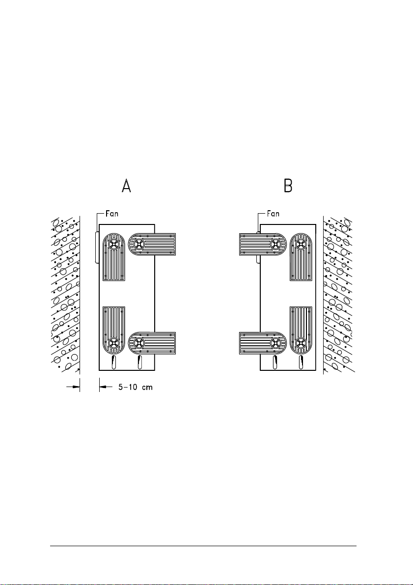
When standing the system with the fan facing the wall, leave 5 - 10 cm space
from the wall for normal air circulation, then position the feet as in Figure 12A.
When standing the system with the fan facing out, you can put the unit close
to the wall and position the feet as in Figure 1-2B.
Figure 1-2 Standing the System Against a Wall
1-4 Owner's Handbook
Page 22
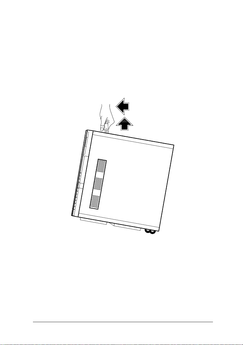
1.1.4 Moving the System
The system housing has a handle on top and two wheels at the base for easy
moving.
Figure 1-3 shows how to move the system.
Figure 1-3 Moving the System
NOTE: Be sure to close the feet of the system before
moving it.
System Housing 1-5
Page 23
1.2 Features
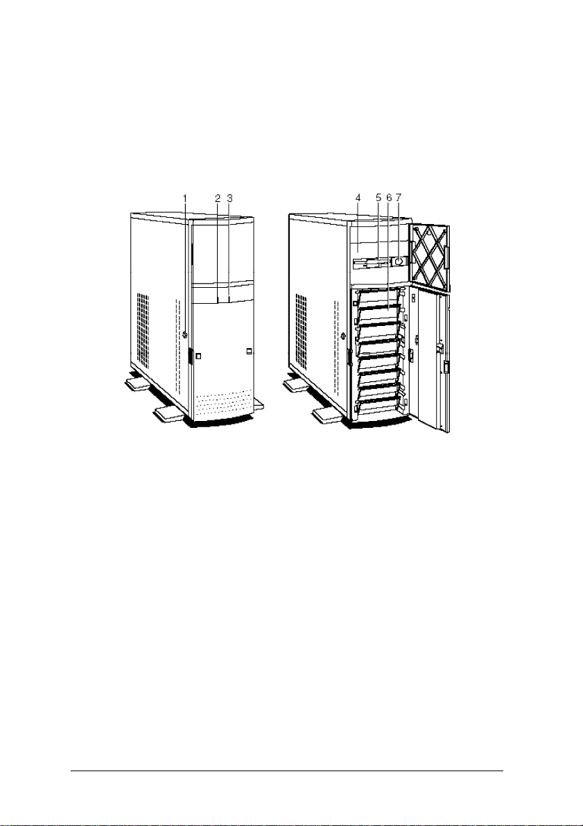
1.2.1 Front Panel
1. Keylock 5. 3.5-inch Diskette Drive
2. Fixed Disk Drive LED 6. 3.5-inch Fixed Disk Drive Bays
3. Power LED 7. Power Button
4. 5.25-inch Drive Bays
Figure 1-4 Front Panel
1-6 Owner's Handbook
Page 24

Table 1-1 Features and Functions of the Front Panel
Feature Function
Keylock Locks the system housing
Fixed Disk Drive LED Indicates fixed disk drive activity
Power LED Indicates that power is applied to
the system
3.5-inch Diskette Drive Accommodates a 3.5-inch diskette
Drive Bays Holds the diskette drives and fixed
disk drives
Power Button Turns the system on or off
System Housing 1-7
Page 25
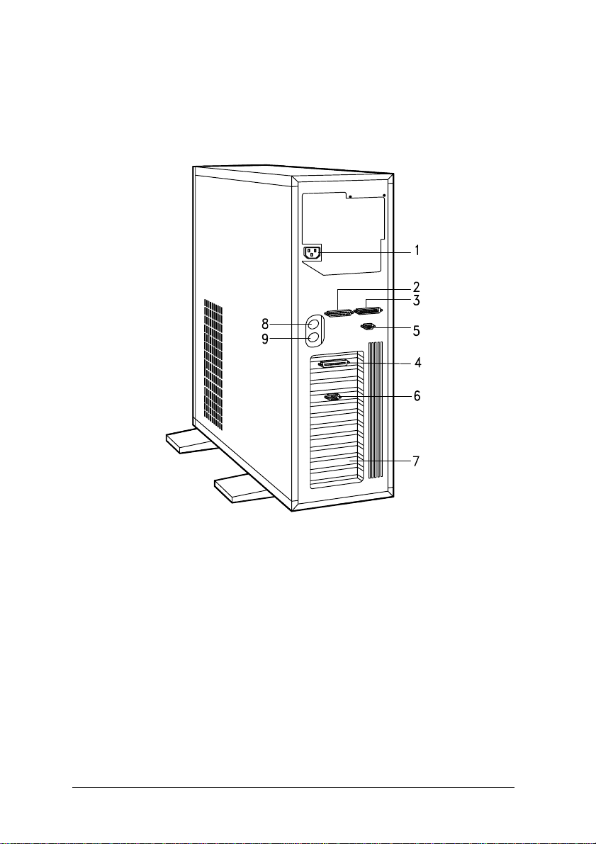
1.2.2 Rear Panel
1. Power Socket 5. Serial Port 1
2. Parallel Port 6. Video Port
3. Serial Port 2 7. Expansion Slots
4. SCSI Port (optional) 8. Keyboard Connector
9. Mouse Connector
Figure 1-5 Rear Panel
1-8 Owner's Handbook
Page 26

Table 1-2 Features and Functions of the Rear Panel
Feature Function
Power Socket Connects the power cable
Parallel Port Connects a parallel printer
Serial Ports Connects serial peripherals
SCSI Port (optional) Connects peripheral devices for
high-speed, parallel data transfer
Expansion Slots For additional expansion boards
Keyboard Connector Connects a PS/2-compatible
keyboard
Mouse Connector Connects a PS/2-compatible mouse
Video Port Connects the video cable
System Housing 1-9
Page 27
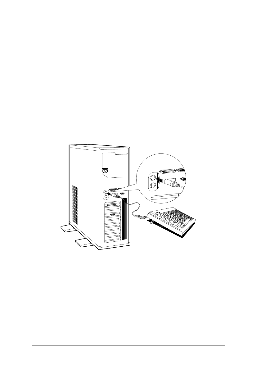
1.3 Connecting the Components
CAUTION: Make sure that the system is turned off before
connecting the system components.
Follow these steps to connect the components:
1. Plug the keyboard into the keyboard socket.
Figure 1-6 Connecting the Keyboard
1-10 Owner's Handbook
Page 28
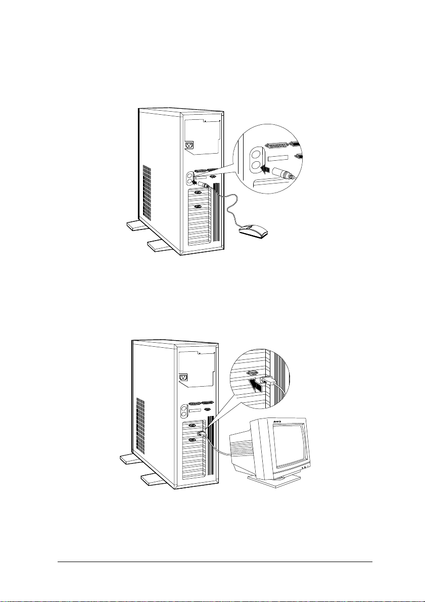
2. Connect the mouse into the mouse connector.
Figure 1-7 Connecting a Mouse
3. Connect the monitor cable into the video socket.
Figure 1-8 Connecting a Monitor
System Housing 1-11
Page 29
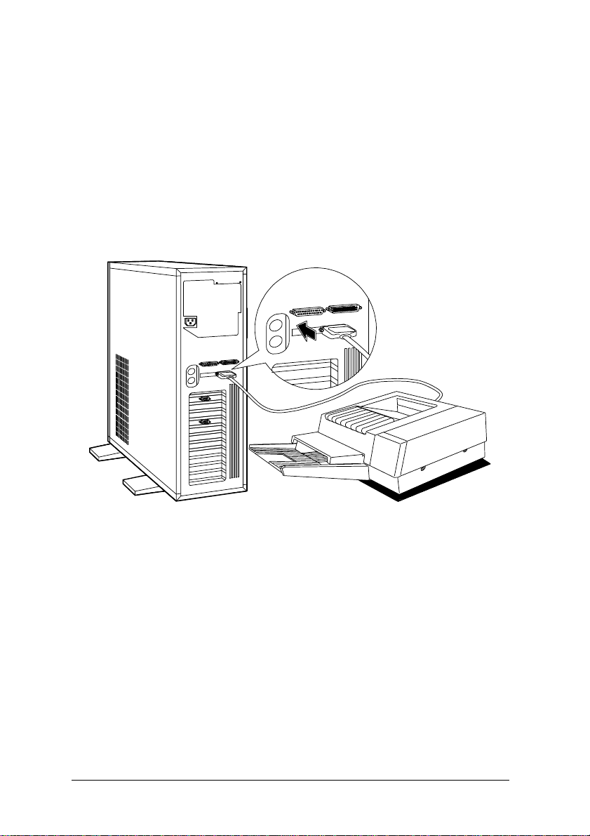
4. If you have a parallel printer, connect it to the parallel port.
If you have a serial printer or other serial peripherals, connect it to a
serial port (Serial 1 or Serial 2).
Figure 1-9 Connecting a Printer
1-12 Owner's Handbook
Page 30
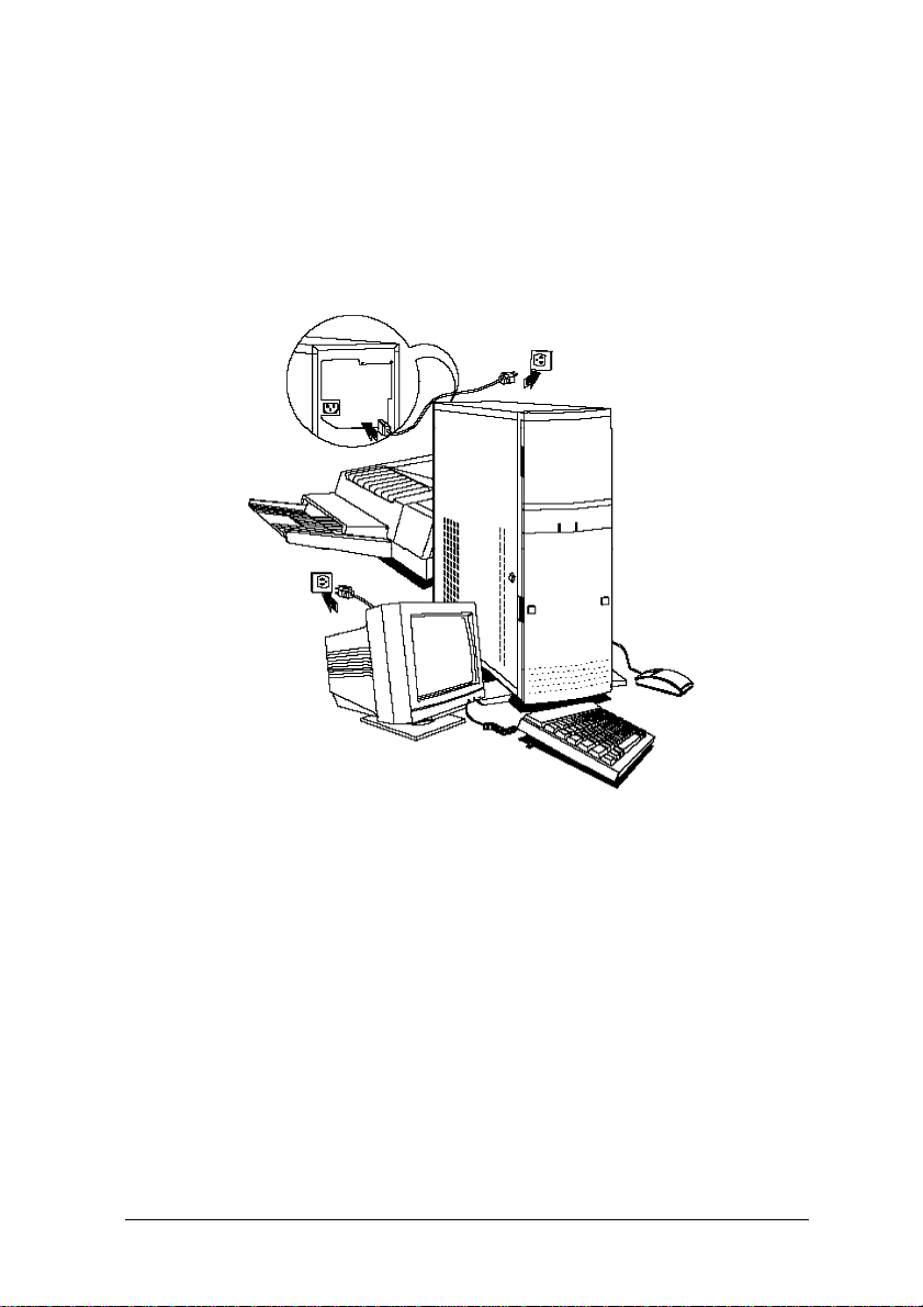
5. Plug the female end of the power connector into the system power socket
and the other end into a grounded electrical outlet.
6. Plug the monitor power cable into a grounded electrical outlet.
Figure 1-10 Connecting the Power Cables
System Housing 1-13
Page 31

1.4 Installing Options
This section tells you how to open the system housing and install additional
components in the system.
1.4.1 ESD Precautions
Integrated circuits (ICs) on expansion boards are sensitive to static electricity.
To avoid damaging the chips with electrostatic discharge (ESD), observe the
following precautions:
1. Do not remove a board from its packaging until you are ready to install
it.
2. Wear a wrist grounding strap before handling electronic components.
Wrist grounding straps are available at most electronic component stores.
1.4.2 Opening the System
When you want to install disk drives and other internal components, you have
to remove the front panel covers and open the system housing.
1-14 Owner's Handbook
Page 32

Follow these steps to open the system:
1. Turn off the system and unplug the power cable from the wall socket.
2. Open the upper front panel cover.
Figure 1-11 Opening the Upper Front Panel Cover
NOTE: The front panel covers are reversible. You can also open
them from the right side following the same procedure.
System Housing 1-15
Page 33

3. Unlock the system housing using the key and open the lower front panel
cover by pressing the button and pulling the cover.
NOTE: You cannot open the lower front panel if the system is
locked.
Figure 1-12 Opening the Lower Front Panel Cover
NOTE: You cannot remove the key after you have unlocked the
housing. You can remove it only when you lock the
housing again.
1-16 Owner's Handbook
Page 34

When installing drives in the 5.25-inch drive bays, you have to remove both
the upper front panel cover and its frame.
4. To remove the front panel cover, hold it on both sides and pull.
5. To remove the upper front panel frame, press the latch under it and pull.
Figure 1-13 Removing the Front Panel Cover and Frame
System Housing 1-17
Page 35

6. Pull on the key to swing the left side of the housing open.
NOTE: If necessary, you may use a screwdriver to gently pry
the side of the housing open.
Figure 1-14 Opening the System Housing
1-18 Owner's Handbook
Page 36

Figure 1-15 shows the inside components.
1. Switching Power Supply
2. Metal Plate (for cable clamp)
3. System Board
4. 5.25-inch Drive Frame
5. 3.5-inch Fixed Disk Drive Frame
Figure 1-15 Inside Components
System Housing 1-19
Page 37

1.4.3 Installing and Removing Expansion Boards
Installing a Board
1. Study the expansion board's installation guide and configure any jumpers
as directed.
2. Remove a bracket from any empty expansion slot. Save the screw to
secure the new board. Keep the bracket for future use.
Figure 1-16 Removing a Bracket
1-20 Owner's Handbook
Page 38

3. Gently insert the board into the expansion slot.
Make sure that the board is properly inserted.
Figure 1-17 Installing a Board
4. Secure the board with the screw.
NOTE: Do not neglect this step. The board uses the screw for
grounding.
Removing a Board
1. Unplug all cables connected to the board.
2. Remove the bracket screw and pull the board out of the slot.
3. Secure a bracket cover to the empty slot.
System Housing 1-21
Page 39

1.4.4 Installing Drives
You can install up to three 5.25-inch drives and one 3.5-inch drive on the
upper frame, and eight externally accessible fixed disk drives on the lower
frame of the system.
Installing a 5.25-inch Diskette Drive
1. Screw the drive guides on the sides of the diskette drive.
Figure 1-18 Attaching the Drive Guides
1-22 Owner's Handbook
Page 40

2. Insert the drive into a 5.25-inch drive bay.
Figure 1-19 Installing a 5.25-inch Diskette Drive
3. Connect the diskette drive cables.
System Housing 1-23
Page 41

Removing a 5.25-inch Diskette Drive
Follow these steps to remove a 5.25-inch diskette drive:
1. Disconnect all the drive cables.
2. Press the metal tabs on the sides of the drive and pull the drive out.
Figure 1-20 Removing a 5.25-inch Diskette Drive
1-24 Owner's Handbook
Page 42

Installing a Fixed Disk
NOTE: When you purchase a fixed disk, make sure that you
have all the cables necessary to install the drive. Don’t
forget to get the bad sector information from your dealer.
Follow these steps to install a fixed disk:
1. Pull out a drive drawer.
NOTE: It is better to install fixed disk drives starting from the
lowest bay.
Figure 1-21 Pulling Out a Fixed Disk Drive Drawer
System Housing 1-25
Page 43

2. Put the fixed disk drive in the drawer and secure it with four screws
under.
Figure 1-22 Installing a Fixed Disk Drive
1-26 Owner's Handbook
Page 44

3. Insert the drive drawer back to the housing.
Figure 1-23 Inserting the Drive Drawer
4. Connect the fixed disk drive cables.
System Housing 1-27
Page 45

1.4.5 Arranging the Cables
After installing drives and connecting all the cables, clip the cables using the
cable clamp attached to the metal plate between the power supply and the
drive bays.
Figure 1-24 Clipping the Cables with the Cable Clamp
1-28 Owner's Handbook
Page 46

C h a p t e r 2
System Board
The system is a high-performance EISA machine designed with a 32/64-bit
auto-detect and auto-switch architecture. It supports both the 486-series
microprocessors and the new Pentium microprocessor, making it a long-range
performance machine.
The system features the single-chip upgrade technology that makes CPU
upgrades easy and economical, and the multiple CPU upgrade technology
that can turn it into a multiprocessor system. It is fully compatible with the
IBM PC/AT and is suitable for use as a multiuser file server, LAN file server
or a CAD/CAE/CAM workstation.
The system board holds the 128-KB system ROM, eight 32-bit EISA expansion
slots, two VESA local bus slots, a CPU board slot, four 72-pin DRAM banks,
and two SCSI connectors (for SCSI models).
Standard features such as two serial ports, one parallel port, diskette drive
interface, and embedded fixed disk drive interface also reside on the system
board.
The system has 8-MB base memory and supports a maximum memory of
256 MB using 64-MB single-density SIMMs. When using the Pentium CPU
board, the system supports up to 256-MB using 32-MB double-density SIMMs.
A graphics accelerator card can be used on the system high-speed 32-bit local
bus to enhance video display capabilities.
System Board 2-1
Page 47

2.1 Major Components
The system board has the following major components:
. Four 72-pin SIMM sockets labeled Bank 0 ~ Bank 3
. DRAM controller with page/faster page mode and burst read capability
. One CPU board slot
. Eight 32-bit EISA expansion slots supporting master/slave add-on cards
. Two VESA local bus slots supporting master/slave add-on cards
. Real-time clock and battery that lasts for approximately 5-7 years
. 128-KB Flash memory
. On-board Fast SCSI-2 host adapter
. 350-watt switching power supply
Figure 2-1 shows the system board layout and the location of the major
components on the system board.
2-2 Owner's Handbook
Page 48

1 Serial 2 9 CPU Board Slot
2 Serial 1 10 VESA Local Bus Slots
3 Diskette Drive Connector 11 BIOS
4 Fixed Disk Drive Connector 12 EISA Slots
5 Power Connector 1 13 Keyboard Controller
6 SIMM Sockets 14 PS/2 Mouse Connector
7 Power Connector 2 15 PS/2 Keyboard Connector
8 SCSI Connectors 16 Parallel Port
Figure 2-1 System Board Layout
System Board 2-3
Page 49

2.2 Upgrading the Memory
The system comes with a standard 8-MB memory. You can upgrade the system
memory by adding memory modules (SIMMs) into the SIMM sockets or by
changing the SIMMs for higher memory configuration. The system supports
three types of single-density SIMMs: 4-MB, 16-MB, and 64-MB.
NOTE: On models using the Pentium CPU board, you can use
only another four 72-pin SIMM sockets. See Chapter 4.
Table 2-1 Memory Configurations
Bank0 Bank1 Bank2 Bank3 Total
4 MB 4 MB
4 MB 4 MB 8 MB
4 MB 4 MB 4 MB 12 MB
4 MB 4 MB 4 MB 4 MB 16 MB
16 MB 16 MB
4 MB 16 MB 20 MB
4 MB 4 MB 16 MB 24 MB
4 MB 16 MB 4 MB 24 MB
4 MB 4 MB 16 MB 4 MB 28 MB
4 MB 16 MB 4 MB 4 MB 28 MB
16 MB 16 MB 32 MB
4 MB 16 MB 16 MB 36 MB
16 MB 16 MB 4 MB 36 MB
4 MB 16 MB 16 MB 16 MB 52 MB
16 MB 16 MB 16 MB 4 MB 52 MB
16 MB 16 MB 16 MB 16 MB 64 MB
64 MB 64 MB
4 MB 4 MB 64 MB 72 MB
16 MB 64 MB 80 MB
4 MB 16 MB 64 MB 84 MB
*
2-4 Owner's Handbook
Page 50

Table 2-1 Memory Configurations* (continued)
Bank0 Bank1 Bank2 Bank3 Total
16 MB 64 MB 4 MB 84 MB
4 MB 4 MB 16 MB 64 MB 88 MB
16 MB 64 MB 4 MB 4 MB 88 MB
16 MB 16 MB 64 MB 96 MB
16 MB 64 MB 16 MB 96 MB
4 MB 16 MB 16 MB 64 MB 100 MB
16 MB 64 MB 16 MB 4 MB 100 MB
16 MB 16 MB 16 MB 64 MB 112 MB
16 MB 64 MB 16 MB 16 MB 112 MB
64 MB 64 MB 128 MB
64 MB 64 MB 4 MB 132 MB
4 MB 4 MB 64 MB 64 MB 136 MB
64 MB 64 MB 4 MB 4 MB 136 MB
16 MB 64 MB 64 MB 144 MB
64 MB 64 MB 16 MB 144 MB
4 MB 16 MB 64 MB 64 MB 148 MB
64 MB 64 MB 16 MB 4 MB 148 MB
16 MB 16 MB 64 MB 64 MB 160 MB
16 MB 64 MB 16 MB 64 MB 160 MB
64 MB 64 MB 16 MB 16 MB 160 MB
64 MB 64 MB 64 MB 192 MB
16 MB 64 MB 64 MB 64 MB 208 MB
64 MB 64 MB 16 MB 64 MB 208 MB
64 MB 64 MB 64 MB 64 MB 256 MB
WARNING! Do not attempt the procedures described in this section
unless you are a qualified service technician.
CAUTION: 1. Read and follow the electrostatic discharge (ESD)
precautions in Chapter 1 before installing SIMMs.
System Board 2-5
Page 51

2. Be careful when inserting or removing SIMMs.
Forcing a SIMM in or out of a socket can damage
the socket.
2.2.1 Installing SIMMs
1. Slip a SIMM at a 45o angle into a socket with the component side facing
down.
NOTE: Always install SIMMs from Bank 0.
2. Gently press the SIMM up until the pegs of the socket slip into the holes
on the SIMM and the holding clips lock the SIMM into position.
o
NOTE: The SIMM should be at 90
angle when installed.
Figure 2-2 Installing a SIMM
2-6 Owner's Handbook
Page 52

2.2.2 Removing SIMMs
Follow these steps when removing SIMMs:
1. Press the holding clips on both sides of the SIMM outward to release it.
o
2. Press the SIMM downwards at about 45
angle.
3. Pull the SIMM out of the socket.
NOTE: Always remove the SIMM from the highest bank first.
2.2.3 Reconfiguring the System
Reconfigure the system after installing or removing SIMMs.
Follow these steps to reconfigure the system:
1. Reboot the system. A memory error message appears, indicating that
the total memory does not match the value stored in CMOS.
2. Press Ctrl-Alt-Esc to run Setup.
A warning message indicating a wrong memory configuration appears.
3. Press Esc twice to exit Setup and reboot the system.
The system boots with the new memory configuration.
System Board 2-7
Page 53

2.3 Upgrading the CPU
The system has a separate board that contains the CPU and the second-level
cache. The single-chip upgrade technology gives you the flexibility to upgrade
the CPU by just plugging in a higher 486 CPU chip, and changing a few
jumper settings on the system board and on the CPU board.
The system also supports the Pentium CPU. And since this machine is designed
as a multiprocessor system, you can install a second Pentium processor into
the upgrade socket of the Pentium CPU board.
NOTE: When upgrading to the Pentium CPU, you have to
replace the 486 CPU board with the Pentium CPU board.
The upgrade CPU or CPU board comes with its corresponding manual. Refer
to Chapters 3 and 4 for detailed instructions on upgrading the CPU.
2-8 Owner's Handbook
Page 54

2.4 SCSI Feature
The system board features a single-chip Fast SCSI-2 host adapter that adds
SCSI I/O capability to the system. The device consists of all the components
found on the state-of-the-art SCSI host adapters such as an onboard
microcontroller, bus master interface controller, and SCSI controllers. In EISA
mode, this device can transfer at a full 33 MB/second burst transfer rate.
2.4.1 Using SCSI
There are four points to remember when using the SCSI feature of your system.
1. Open jumpers JP1 and JP2.
2. Set jumper JP8 to pins 2-3 to select IRQ11. Refer to the list of jumpers
at the end of this chapter.
NOTE: In this system, you can select only IRQ10 or IRQ11.
For best system performance, use IRQ11.
3. Use the SCSI connector CN1 before CN3.
CN3 does not work if CN1 is not used.
4. When installing the SCSI drivers in the EISA Configuration Utility (ECU),
the option “Extended translation for device > 1 GByte” under BIOS
Configuration, should be set to Enable for fixed disks with greater than
1 Gbyte capacity in DOS environment. Set it to Disable for other software
environments.
NOTE: Refer to the SCSI manual for more information.
System Board 2-9
Page 55

2.5 Jumper Settings
You have to change jumper settings on the system board when you upgrade
the CPU or when you want to reconfigure the system.
Follow these steps to change a jumper setting:
1. Pull out the jumper cap from the jumper.
2. Position the jumper cap over the two pins for the desired setting.
3. Gently press the cap onto the pins.
Figure 2-3 shows the locations of the jumpers on the system board.
Figure 2-3 System Board Jumper Settings
2-10 Owner's Handbook
Page 56

Table 2-2 lists the system board jumpers and their corresponding settings.
Table 2-2 System Board Jumper Settings
Jumper Settings Function
High Speed Write for Local Bus
JP3 1-2
*
0 min. wait
2-3 1 min. wait
CPU Speed Select for VESA Local Bus
JP4 1-2
*
<=33 MHz
2-3 > 33 MHz
Security Enable/Disable
JP6 1-2 Security enable
Reset Button Enable
JP7 Closed
2-3
*
*
Security disable
Reset Enable
Open Reset Disable
IRQ Select
JP8 1-2 IRQ 10
Buzzer/Speaker Select
JP9 1-2
2-3
*
*
IRQ 11
Onboard Buzzer
2-3 External Speaker
System Board 2-11
Page 57

2.6 Error Messages
Whenever you receive an error message of any type, do not continue using the
computer. Note the message and take corrective action. This section describes
the different types of error messages and corresponding corrective measures.
There are two general types of error messages:
. Software
. System
2.6.1 Software Error Messages
Software messages are returned by your operating system or application. These
messages typically occur after you boot the operating system or when you run
your application programs. If you receive this type of message, consult your
application or operating system manual for help.
2.6.2 System Error Messages
A system error message indicates a problem with the computer itself. It
normally appears during the power-on self-test, before the operating system
prompt appears. Table 2-3 lists the system error messages.
Table 2-3 System Error Messages
Error Message Corrective Action
Bad CMOS Battery Replace the battery.
Contact your dealer.
CMOS Checksum Error Rerun the Setup program.
Equipment Configuration Error Rerun the Setup program.
2-12 Owner's Handbook
Page 58

Table 2-3 System Error Messages (continued)
Error Message Corrective Action
Diskette Drive Error Diskette may be bad. If not,
replace the diskette drive.
Diskette Drive Controller Error Check and connect the
DRAM Configuration Error Modify DRAM configuration
Fixed Disk Controller Error Check and connect the
Fixed Disk 0 Error Check all cable connections.
Fixed Disk 1 Error Check all cable connections.
Fixed Disk 0 Extended Type Error Rerun the Setup program.
Fixed Disk 1 Extended Type Error Rerun the Setup program.
Keyboard Error Check and connect the keyboard
Keyboard Interface Error Contact your dealer.
Keyboard Locked Unlock the keyboard.
control cable to the diskette
drive or controller.
to agree with one of the
options in Table 2-1.
control cable to the fixed
disk drive or controller.
Replace fixed disk.
Replace fixed disk.
to the system unit.
I/O Parity Error Contact your dealer.
System Board 2-13
Page 59

Table 2-3 System Error Messages (continued)
Error Message Corrective Action
Memory Error Check SIMMs on the system
board. Contact your dealer.
Memory Size Mismatch Rerun Setup.
Pointing Device Error Check and connect
pointing device.
Pointing Device Interface Error Contact your dealer.
Press F1 key to continue or Press F1 or Ctrl-Alt-Esc.
Ctrl-Alt-Esc for Setup
Press F1 to Setup or other key to Press F1 and reconfigure
continue ...... the system.
Press Esc to turn off NMI, Press Esc to disregard NMI
any other key to reboot error. Press any other key
Protected Mode Test Fail Contact your dealer.
RAM BIOS Error Contact your dealer.
to reboot the system.
RAM Parity Error Check SIMMs on system
board or contact your dealer.
Real Time Clock Error Rerun Setup.
Shadow RAM Fail Contact your dealer.
System Memory Address Error Check SIMMs on system
2-14 Owner's Handbook
board or contact your dealer.
Page 60

2.6.3 Correcting Error Conditions
As a general rule, if an error message says “Press F1 to continue,” it is caused
by a configuration problem, which can be easily corrected. An equipment
malfunction is more likely to cause a so-called fatal error, i.e., an error that
causes complete system failure.
Here are some corrective actions for error messages:
1. Run Setup. You must know the correct configuration values for your
system before you enter Setup, which is why you should write them
down when the system is correctly configured. An incorrect Setup
configuration is a major cause of power-on error messages, especially
for a new system.
2. Remove the system unit cover, following the directions in Chapter 1.
Check that the jumpers on the system board and any expansion boards
are set correctly.
3. If you cannot access a new disk, it may be because your disk is not
physically formatted. Physically format the disk first using the FDISK
and FORMAT commands.
4. Check that all connectors and boards are securely plugged in. Review
the sections in Chapter 1 for assistance.
If you go through the corrective steps above and still receive an error message,
the cause may be an equipment malfunction.
If you are sure that your configuration values are correct and your battery is in
good condition, the problem may lie in a damaged or defective chip.
In both cases, contact an authorized service centre for assistance.
System Board 2-15
Page 61

2.7 Address Maps and Interrupt Table
2.7.1 System Memory Map
Table 2-4 System Memory Map
Address Name Function
00000000 ~ 640 KB Onboard DRAM
0009FFFF System Memory
000A0000 ~ 128 KB Reserved for Graphics
000BFFFF Video RAM Display Buffer
000C0000 ~ 64-KB Reserved for ROM on
000CFFFF I/O Expansion ROM I/O Adapters
00D0000 ~ 16-KB Reserved for SCSI BIOS
00D3FFF for SCSI BIOS
00D4000 ~ 16-KB Reserved for ROM on
00D7FFF I/O Expansion ROM I/O Adapters
00D8000 ~ 16-KB Reserved for SCSI BIOS
00DBFFF for SCSI BIOS
(non-cacheable)
00DC000 ~ 16-KB Reserved for ROM on
00DFFFF I/O Expansion ROM I/O Adapters
00E0000 ~ 32 KB Reserved for
00E7FFF Extended System BIOS
00E8000 ~ 32 KB Reserved for
00EFFFF Extended System BIOS
2-16 Owner's Handbook
Page 62

Table 2-4 System Memory Map (continued)
Address Name Function
00F0000 ~ 64 KB BIOS System ROM BIOS (ROM)
00FFFFF System RAM BIOS
0100000 ~ System Memory Onboard DRAM
0F9FFFFF
0FA0000 ~ 384 KB Reserved for Memory Map
0FFFFFF I/O Card Memory I/O Card (Non-cacheable)
1000000 ~ System Memory Onboard RAM
FFFFFFF
System Board 2-17
Page 63

2.7.2 I/O Address Map
Table 2-5 System I/O Address Map
Address
Range (hex) Device
000 ~ 01F DMA Controller-1, 8273
020 ~ 027 Interrupt Controller-1, 8259
030 ~ 037 Interrupt Controller-1, 8259
040 ~ 047 System Timer (8254-1)
050 ~ 057 System Timer (8254-1)
060 ~ 06F Keyboard Controller 8742
070 ~ 07F Real-Time Clock, NMI Mask
080 ~ 09F DMA Page Register 74LS612
0A0 ~ 0BF Interrupt Controller-2, 8259
0C0 ~ 0DF DMA Controller-2, 8237
0F0 Clear Math Coprocessor BUSY
0F1 Reset Coprocessor
0F8 ~ 0FF Math Coprocessor
*
800 ~ 8FF NV RAM Address
2-18 Owner's Handbook
Speed Status Register
Page 64

Table 2-5 System I/O Address Map (continued)
Address
Range (hex) Device
*
C80 ~ C83 EISA Product System ID
*
CFB NV RAM Page Address (New Mode)
*
4F0 SCSI Address, CPU and Memory Type
1F0 ~ 1F7 Fixed Disk
278 ~ 27F Parallel Port 2
2F8 ~ 2FF Serial Port 2
378 ~ 37F Parallel Port 1
3B0 ~ 3BF Monochrome Display
3C0 ~ 3CF EGA, VGA, SVGA
Select 8K or 9K SRAM (in separate mode)
Flash ROM Programming
IRQ12 Enable,
3.5" Diskette 3 Mode Select
3D0 ~ 3DF CGA, VGA, SVGA
3F0 ~ 3F7 Floppy Disk Controller
3F7 ~ 3FF Serial Port 1
System Board 2-19
Page 65

2.7.3 Interrupt Levels
Table 2-6 Interrupt Requests Used
Interrupt Interrupt Source
IRQ0 Timer Output 1
IRQ1 Keyboard
IRQ3 Serial Port 2
IRQ4 Serial Port 1
IRQ6 Floppy Disk
IRQ7 Printer Port
IRQ8 Real-Time Clock
IRQ12 PS/2 Mouse
IRQ13 Numeric Processor
IRQ14 Embedded Hard Disk
2-20 Owner's Handbook
Page 66

C h a p t e r 3
486 CPU Board
The 486 CPU board supports several 486 CPU types such as:
. 486SX/33
. 486DX/33
. 486DX/50
. 486DX2/50
. 486DX2/66
. P24T (Pentium Upgrade)
You can easily upgrade the CPU using single-chip upgrade technology. This
means you only have to remove the old CPU, plug in the new one, and change
a few jumper settings.
The 486 CPU board also carries a standard 256-KB second-level cache memory
expandable to a maximum of 1 MB.
WARNING! Do not attempt to make any hardware changes in your
system if you are not a qualified technician. Ask your
dealer for assistance.
Figure 3-1 shows the CPU board layout.
486 CPU Board 3-1
Page 67

1 486 CPU Socket
2 Second-level Cache
Figure 3-1 486 CPU Board Layout
3-2 Owner's Handbook
Page 68

3.1 Upgrading the CPU
This section gives instructions for upgrading the CPU.
NOTE: Read the electrostatic discharge (ESD) precautions in
Chapter 1 before unpacking and installing the upgrade
CPU.
3.1.1 Installing the Upgrade CPU
Follow these steps to install the upgrade CPU:
1. Turn off the system and unplug the power cable from the wall socket.
2. Detach the CPU board from the system board.
3. Detach the heat sink by removing the clip and the four screws securing it
to the CPU board.
The heat sink is a platform that protects the upgrade CPU from excessive
heat.
4. Locate the CPU socket and remove the CPU installed in it.
5. Plug-in the upgrade CPU into the socket.
NOTE: Make sure that pin 1 of the CPU corresponds to pin 1
of the socket. Insert the CPU pins into the socket
pinholes gently but firmly. Be careful not to bend any
pins.
486 CPU Board 3-3
Page 69

6. Change the appropriate jumper settings on the 486 CPU board. Refer to
section 3.3 for the jumper settings.
7. Re-attach the heat sink to the board with the four screws and the clip.
8. Change the appropriate jumper settings on the system board. Refer to
section 2.5 for the jumper settings.
9. Re-install the CPU board to the system board.
10. Reconnect the cables.
NOTE: If you are upgrading to Pentium CPU, you have to
change the 486 CPU board with a Pentium CPU board.
Read the manual that comes with the Pentium CPU
board for more information.
3.2 Upgrading the Second-Level Cache
The 486 CPU board has a standard 256 KB of cache memory expandable to
1 MB. The cache memory is a high-speed buffer between the main memory
and the CPU. It stores frequently-used instructions and data, greatly reducing
the CPU memory access time and ultimately improves system performance.
NOTE: Read the electrostatic discharge (ESD) precautions in
Chapter 1 before handling chips.
3-4 Owner's Handbook
Page 70

Follow these steps to upgrade the second-level cache:
1. Turn off the system and unplug the power cable from the wall socket.
2. Detach the CPU board from the system board.
3. Detach the heat sink by removing the clip and the four screws securing it
to the CPU board.
4. Remove the original SRAM chips.
5. Carefully insert the new SRAM chips on the sockets. Be careful not to
bend any pins.
6. Change the appropriate jumper settings. Refer to Table 3-2 for the settings.
7. Re-attach the heat sink to the board with the four screws and the clip.
8. Re-install the CPU board to the system board and connect the appropriate
cables.
Table 3-1 lists the second-level cache upgrade options.
Table 3-1 Second-level Cache Upgrade (486 CPU Board)
Cache Size SRAM Tag RAM Dirty RAM
64 KB 8K*8 x 8 8K*8 x 1 16K*1 x 1
128 KB 32K*8 x 4 8K*8 x 1 16K*1 x 1
256 KB 32K*8 x 8 32K*8 x 1 64K*1 x 1
1 MB 128K*8 x 8 128K*8 x 1 64K*1 x 1
486 CPU Board 3-5
Page 71

3.3 Jumper Settings
You have to change some jumper settings on the CPU board when you upgrade
the CPU.
Figure 3-2 shows the jumper locations on the 486 CPU board.
Figure 3-2 486 CPU Board Jumper Locations
3-6 Owner's Handbook
Page 72

Table 3-2 lists the jumpers on the 486 CPU board and their corresponding
settings.
Table 3-2 486 CPU Board Jumper Settings
Jumper Settings Function
CPU Clock Frequency Setting
JP1 Open 25 MHz (DX2-50)
Closed 40 MHz
33 MHz (DX2-66)
50 MHz
JP2 Open 25 MHz (DX2-50)
Closed 33 MHz (DX2-66)
PGA CPU Type Setting
JP4 Open 486DX, 486DX2
LADS Setting for VESA Local Bus (Master Support)
JP3 1-2
Local Bus Enabling
JP10 1-2 Disable
System Speed
JP8 1-2 25 MHz, 33 MHz
JP9 1-2 25 MHz, 40 MHz
1-2 486SX
2-3 487SX, ODP 486SX, P24T
*
2-3 50 MHz
*
2-3
2-3 40 MHz, 50 MHz
2-3 33 MHz, 50 MHz
40 MHz
50 MHz
33 MHz
Enable
486 CPU Board 3-7
Page 73

Table 3-2 486 CPU Board Jumper Settings (continued)
Jumper Settings Function
SRAM (Cache) Size
JP11, JP19 Open 64 KB
Closed 128 KB, 256 KB, 1 MB
JP12, JP20 Open 64 KB, 128 KB
JP13, JP14, JP18 Open 64 KB, 128 KB, 256 KB
SRAM (Cache) Size
JP15, JP16 1-2 When using a single bank
Closed 256 KB, 1 MB
Closed 1 MB
(128 KB)
2-3 When using double banks
(64 KB, 256 KB, 1 MB)
3-8 Owner's Handbook
Page 74

C h a p t e r 4
Pentium CPU Board
The Pentium CPU board contains the Pentium CPU, 512-KB second-level
cache expandable to 1 MB, four 72-pin SIMM sockets, and another socket for
a second Pentium CPU.
A system with a Pentium CPU Board can easily be upgraded to a multiprocessor
system. To upgrade to two Pentium CPUs, simply install the second CPU into
the upgrade socket.
When you upgrade to a higher speed Pentium CPU, you have to change the
oscillator with a higher speed also.
WARNING! Do not attempt to make any hardware changes in your
system if you are not a qualified technician. Ask your
dealer for assistance.
Figure 4-1 shows the Pentium CPU board layout.
Pentium CPU Board 4-1
Page 75

1 SIMM Sockets
2 Second Pentium CPU Socket
3 Pentium CPU
4 Upgrade SRAM Sockets
5 SRAM
Figure 4-1 Pentium CPU Board Layout
4-2 Owner's Handbook
Page 76

4.1 Upgrading to Dual CPUs
You can increase the system computing power by installing a second Pentium
CPU into the upgrade socket on the Pentium CPU board.
NOTE: Read the electrostatic discharge (ESD) precautions in
Chapter 1 before unpacking and installing the upgrade
CPU.
4.1.1 Installing the Second CPU
Follow these steps to install the second Pentium CPU:
1. Turn off the system and unplug the power cable from the wall socket.
2. Detach the Pentium CPU board from the system board.
3. Detach the heat sink by removing the clip and the four screws securing it
to the CPU board. (You do not need to remove the fan from the heat
sink.)
4. Locate the second CPU socket and plug-in the new CPU.
NOTE: Make sure that pin 1 of the CPU corresponds to pin 1
of the socket. Insert the CPU pins into the socket
pinholes gently but firmly. Be careful not to bend any
pins.
5. Re-attach the heat sink to the board with the four screws and the clip.
6. Re-install the CPU board to the system board.
7. Reconnect the cables.
8. Reconfigure the system using the EISA Configuration Utility (ECU).
Refer to Chapter 6 for details.
Pentium CPU Board 4-3
Page 77

4.2 Upgrading the Second-Level Cache
The Pentium CPU board has a standard 512 KB of cache memory expandable
to 1 MB.
NOTE: Read the electrostatic discharge (ESD) precautions in
Chapter 1 before handling chips.
Follow these steps to upgrade the second-level cache:
1. Turn off the system and unplug the power cable from the wall socket.
2. Detach the CPU board from the system board.
3. Detach the heat sink by removing the clip and the four screws securing it
to the CPU board. (You do not need to remove the fan from the heat
sink.)
4. Remove the original SRAM chips.
5. Carefully insert the new SRAM chips on the sockets. Be careful not to
bend any pins.
6. Change the appropriate jumper settings. Refer to Table 4-3 for the settings.
7. Re-attach the heat sink to the board with the four screws and the clip.
8. Re-install the CPU board to the system board and connect the appropriate
cables.
Table 4-1 Second-level Cache Upgrade (Pentium CPU Board)
SRAM Tag RAM Dirty RAM
Cache Size
512 KB 32K*8 x 16 32K*8 x 1 16K*1 x 1
1 MB 128K*8 x 8 32K*8 x 1 64K*1 x 1
4-4 Owner's Handbook
(15 ns) (12 ns) (12 ns)
Page 78

4.3 Upgrading the Memory
The Pentium CPU board has four 72-pin SIMM sockets that support up to
256-MB RAM using 4-MB, 8-MB, 16-MB, and 32-MB SIMMs.
With the additional four SIMM sockets, the system has a total of eight sockets
for a maximum memory upgrade of 256 MB in 256 combinations.
NOTE: You have to use the same type of SIMMs in each bank.
You have to run Setup after installing additional memory.
The memory bank configuration of the system board changes when you are
using the Pentium CPU board. Instead of one SIMM socket being one bank,
two sockets are counted as one bank, as follows:
Memory Banks
System Board
Sockets 0 and 1 Bank 0
Sockets 2 and 3 Bank 1
Pentium CPU Board
Sockets 0 and 1 Bank 2
Sockets 2 and 3 Bank 3
Pentium CPU Board 4-5
Page 79

You can upgrade the system memory using any combination of the SIMMs
supported by the system.
Table 4-2 lists some examples of available memory configurations.
Table 4-2 Memory Configurations
System Board Pentium CPU Board
Bank0 Bank1 Bank2 Bank3 Total
4MB 4MB 8MB
4MB 4MB 8MB 8MB 24MB
4MB 4MB 8MB 8MB 16MB 16MB 56MB
4MB 4MB 8MB 8MB 16MB 16MB 32MB 32MB 120MB
4MB 4MB 4MB 4MB 4MB 4MB 4MB 4MB 32MB
8MB 8MB 8MB 8MB 8MB 8MB 8MB 8MB 64MB
16MB 16MB 16MB 16MB 16MB 16MB 16MB 16MB 128MB
32MB 32MB 32MB 32MB 32MB 32MB 32MB 32MB 256MB
4.4 Jumper Settings
You have to change some jumper settings on the CPU board when you install
a second CPU.
Figure 4-2 shows the jumpers on the Pentium CPU board and their locations.
Figure 4-2 Pentium CPU Board Jumper Locations
4-6 Owner's Handbook
Page 80

Table 4-3 lists the jumpers on the Pentium CPU board and their corresponding
settings.
Table 4-3 Pentium CPU Board Jumper Settings
Jumper Settings Function
Local Bus
JP4 1-2
*
Enable
2-3 Disable
SRAM (Cache) Type
JP8 1-2 When using a single bank
2-3 When using double banks
JP9 1-2 When using a single bank
2-3 When using double banks
SRAM (Cache) Size
JP10, JP13 Open 128 KB
Closed 256 KB, 512 KB, 1 MB
JP11, JP14 Open 128 KB, 256 KB
Closed 512 KB, 1 MB
JP12, JP15 Open 128 KB, 256 KB, 512 KB
Closed 1 MB
*
Default Setting
Pentium CPU Board 4-7
Page 81

C h a p t e r 5
Configuring the System
Most systems are already configured by the manufacturer or dealer. There is
no need to run Setup when starting the computer unless you get a "Run Setup"
message.
The Setup program loads configuration values into the battery-backed,
nonvolatile memory called CMOS RAM. This memory area is not part of the
system RAM.
NOTE: If you repeatedly receive "Run Setup" error messages,
check the computer’s internal battery. If the battery is
dead or not properly connected, the system cannot
retain configuration values in CMOS RAM.
You can access the Setup configuration values by pressing Ctrl-Alt-Esc.
Before running Setup, have the following information ready:
. Diskette drive type. The standard system diskette drive type is 1.44 MB.
. Fixed disk drive type. To determine your drive type, compare the
information on the label pasted to your fixed disk (or supplied in vendor
documentation) with the disk types listed in at the end of this chapter.
Configuring the System 5-1
Page 82

The values in the System Configuration are the basic hardware settings of your
system. You have to change some of them if you add or remove any system
component.
CAUTION: Close all open files and leave your application program
before entering Setup. You cannot exit back into an
application. The system automatically reboots when
you leave Setup.
Press the key combination Ctrl-Alt-Esc to enter the BIOS Utility. The Setup
main menu appears:
BIOS Utility
System Configuration
System Security
= Move Highlight Bar, = Select, Esc = Exit
NOTE: The BIOS version of the system depends on the CPU
installed. The following sections discuss the 486 and
Pentium versions separately.
5-1 Owner's Handbook
Page 83

5.1 Basic System Configuration (486 CPU)
The following screen appears when you select System Configuration from the
main menu:
System Configuration Page 1
Basic System Configuration
Advanced System Configuration
WARNING
The following parameters in the Advanced System Configuration depend
on CPU in use. Press F9 to set the default value for the best system
performance. The system may hang if any of these parameters are set
incorrectly.
= Move Highlight Bar, = Select, Esc = Exit
Select the first option to show the Basic System Configuration screens as in the
following page.
Configuring the System 5-1
Page 84

Basic System Configuration Page 1
Date-------------------------------------- [MM/DD/YY]
Time ------------------------------------- [HH:MM:SS]
Diskette Drive A ---------------------- [xx-MB xx-inch]
Diskette Drive B ---------------------- [xx-MB xx-inch]
-------------------------------------------- Cylinder Head Sector Landing Pre_Comp
Fixed Disk 0 ---------------------- [ xx] xx xx xx xx None
Fixed Disk 1 ---------------------- [ xx] xx xx xx xx None
Base Memory ------------------------- [ xxx] KB
Extended Memory-------------------- [ xxxx] KB
Total Memory-------------------------- [ xxxx] KB
Math Coprocessor ------------------- [ Installed ]
Primary Display ----------------------- [VGA/EGA]
= Move Highlight Bar, = Change Setting, PgDn/PgUp = Move Screen
F9 = Default Setting, F10 = Bootable Setting, F1 = Help, Esc = Exit
BIOS Setup Utility----------------------------------- Page 2
Communication Status
Baud Rate ---------------------------------------------------- [ 110 ] BPS
Parity ---------------------------------------------------------- [None]
Stop Bits ------------------------------------------------------ [ 1 ] Bits
Data Length -------------------------------------------------- [ 7 ] Bits
Memory Test ------------------------------------------------------ [Auto]
= Move Highlight Bar, = Change Setting, PgDn/PgUp = Move Screen
F9 = Default Setting, F10 = Bootable Setting, F1 = Help, Esc = Exit
5-1 Owner's Handbook
Page 85

5.1.1 The Real-Time Clock
The real-time clock keeps the system date and time. After setting the date and
time, you need not enter them every time you turn on the system unit. As long
as the internal battery remains good (approximately seven
the clock continues to keep the date and time accurately even when the power
is off.
Date
Highlight this parameter to set the date. Enter the current date, following the
month-day-year format. Whenever you want to change the date, simply
highlight the Date parameter and enter the new date.
Time
Highlight this parameter and enter the current time in the hour-minute-second
format to set the time. Whenever you want to change the time, simply highlight
the Time parameter and enter the new time.
years) and connected,
5.1.2 Diskette Drives
Highlight the Diskette Drive A parameter to enter the configuration value for
the first diskette drive (drive A).
Press the left- and right-arrow keys to view the options.
Follow the same steps to enter the value for the Diskette Drive B parameter.
Choose None if you don’t have a second diskette drive.
5.1.3 Fixed Disk Drives
Know the type of your fixed disk before you set the fixed disk drive parameters.
NOTE: See the label on the fixed disk or refer to the vendor's
documentation for the fixed disk drive type. See also the
list of fixed disk drive types at the end of this chapter.
Configuring the System 5-1
Page 86

Move the highlight bar to the Fixed Disk 0 parameter to configure the fixed disk
drive (drive C).
Use the arrow keys to select the value that corresponds to your fixed disk type.
Follow the same steps to set the value for Fixed Disk 1 parameter. Select None
if you don’t have a second fixed disk.
5.1.4 System Memory
The system detects the total amount of system memory during POST and sets
the values of the memory parameters accordingly. If you install additional
memory, the system automatically adjusts the values to show the new memory
size.
5.1.5 Math Coprocessor
The system CPU already includes a math coprocessor so this parameter shows
Installed.
5.1.6 Video Display
The video display is the monitor on which the operating system prompt appears
when you boot the system. The system detects the video mode of your primary
display and sets the corresponding configuration value. The value may be:
. Monochrome
. CGA 40 columns x 25 rows
. CGA 80 columns x 25 rows
. Special card (VGA/EGA)
5-1 Owner's Handbook
Page 87

5.1.7 Communication Settings
The Communication Settings parameters let you set the baud rate, parity, stop
bit and data length for the first 9-pin serial port (COM 1).
. Baud rate : 110 to 9600 bits per second (BPS)
. Parity : Odd, Even, or None
. Stop bits : 1 or 2 stop bits
. Data length : 7- or 8-bit data word
There is one restriction on the options available for the communication status
parameters. If your data length parameter is an 8-bit data word, you must select
one of the following combinations:
. 1 stop bit and odd or even parity
. 2 stop bits and no parity
The default values are 9600 BPS, odd parity, 1 stop bit, and 7-bit data word.
5.1.8 Memory Test
When you set this parameter to Enable, the system tests the memory at poweron. When you set it to Disable, the system skips the memory test.
Configuring the System 5-1
Page 88

5.2 Basic System Configuration
(Pentium CPU)
In the Pentium version, the following screen appears when you select System
Configuration from the main menu:
System Configuration Page 1
Basic System Configuration
Advanced System Configuration
WARNING
The following parameters in the Advanced System Configuration depend
on CPU in use. Press F9 to set the default value for the best system
performance. The system may hang if any of these parameters are set
incorrectly.
Cache Read Cycle Create Write Cycle
Memory Block Configuration
= Move Highlight Bar, = Select, Esc = Exit
The Basic System Configuration screens are the same as the 486 version. Refer
to section 5.1 for the descriptions of the parameters.
5-1 Owner's Handbook
Page 89

5.3 Advanced System Configuration
(486 CPU)
The Advanced Configuration parameters let you adjust the other system
features for better performance.
When you select Advanced System Configuration from the main menu, the
following screens appear:
Advanced System Configuration Page 1
Shadow RAM
F0000H-FFFFFH (System BIOS)----------------------- [Enabled ]
C0000H-C7FFFH (Video BIOS)------------------------- [Enabled ]
C8000H-CFFFFH ------------------------------------------- [Enabled]
D0000H-D7FFFH ------------------------------------------- [Enabled ]
D8000H-DFFFFH ------------------------------------------- [Enabled ]
E0000H-E7FFFH ------------------------------------------- [Disabled]
Internal Cache (CPU Cache) ----------------------------------- [Enabled ]
System Cache (External Cache) ------------------------------ [Enabled ]
Cache Scheme ---------------------------------------------- [Write Back]
Cache Burst Read Wait-State --------------------------- [2-2-2-2]
Cache Write Cycle Insert Wait--------------------------- [Disabled]
F0000h-FFFFFh (System BIOS)------------------------ [ Cacheable ]
C8000h-C7FFFh (Video BIOS)-------------------------- [ Cacheable ]
= Move Highlight Bar, = Change Setting, PgDn/PgUp = Move Screen
F9 = Default Setting, F10 = Bootable Setting, F1 = Help, Esc = Exit
Configuring the System 5-1
Page 90

Advanced System Configuration Page 2
Hidden Refresh ------------------------------------------------------ [Enabled ]
CPU-DRAM Read Cycle Insert Wait --------------------------- [Disabled]
CPU-DRAM Write Cycle Insert Wait --------------------------- [Disabled]
SCSI I/O ROM Mapping ------------------------------------------- [0D0000H]
= Move Highlight Bar, = Change Setting, PgDn/PgUp = Move Screen
F9 = Default Setting, F10 = Bootable Setting, F1 = Help, Esc = Exit
*
The parameter values on the screens may not be the same as the
ones on your machine.
The default settings are the values initially stored in ROM. If in the future you
change these settings, you can load the default settings again by pressing F9.
When you add a component to the system, you may have to change some
settings. If the system does not boot, use the bootable settings to boot the
system. To do this, press F10 before you turn on the power and hold it until you
hear two beeps. The system then automatically sets the CMOS values to
bootable settings.
5-1 Owner's Handbook
Page 91

5.2.1 Shadow RAM
The system reserves 384 KB of random access memory (RAM) for shadow
RAM. This parameter has seven range addresses. When you set these addresses
to Enable, the video BIOS, I/O ROM, and system BIOS functions run directly
from the shadow RAM. When you set them to Disable, the functions run
normally from ROM.
The address F0000h-FFFFFh is for system BIOS and C0000h-C7FFFh is for
shadowing video BIOS. The next five address ranges, C8000h to EFFFFh, are
for I/O ROM functions.
The System BIOS default setting is Enable while its bootable setting is Disable.
5.2.2 Internal Cache
The Internal Cache is the buffer in the CPU itself. The default setting is
Enabled.
5.2.3 System Cache
Set the cache controller on and off with this parameter. The default setting is
On. The bootable setting is Off.
Cache Scheme
The Cache Scheme parameter sets the cache to Write Back or Write Buffer
modes. Write Back updates the cache but not the memory when there is a write
instruction. It updates the memory only when the cache is already full. Write
Buffer updates both the memory and the cache whenever there is a write
instruction.
For better system performance, both the system default and bootable setting is
Write Back.
Configuring the System 5-1
Page 92

Cache Burst Read Wait-State
This parameter sets cache read cycle for proper system operation. When it is
set Enabled, the cache read delay is longer and the system is more stable.
Cache Write Cycle Insert Wait
This parameter sets cache write cycle for proper system operation. When it is
set Enabled, the cache write delay is longer and the system is more stable.
F0000h-FFFFFh (System BIOS)
If the system BIOS is shadowed and set to Enabled, you may select Cacheable
or Noncacheable for this parameter.
Cacheable allows the system BIOS to run directly from cache memory. The
system functions faster. If it is set to Noncacheable, the system BIOS runs from
RAM.
C0000h-C7FFFh (Video BIOS)
If the system BIOS is shadowed and set to Enabled, you may select Cacheable
or Noncacheable for this parameter.
The Cacheable setting allows the video BIOS to run directly from cache
memory. The system functions faster. If it is set to Noncacheable, the video
BIOS runs from RAM.
5.3.4 SCSI I/O ROM Mapping
This parameter enables you to adjust the address type of the I/O ROM for the
on-board SCSI BIOS when the address conflicts with another add-on card.
5-1 Owner's Handbook
Page 93

5.3 Advanced System Configuration
(Pentium CPU)
In the Pentium BIOS version, when you select Advanced System Configuration
from the main menu, the following screens appear:
Advanced System Configuration Page 1
Shadow RAM
F0000H-FFFFFH (System BIOS)----------------------- [Enabled ]
C0000H-C7FFFH (Video BIOS)------------------------- [Enabled ]
C8000H-CFFFFH ------------------------------------------- [Enabled]
D0000H-D7FFFH ------------------------------------------- [Enabled ]
D8000H-DFFFFH ------------------------------------------- [Enabled ]
E0000H-E7FFFH ------------------------------------------- [Disabled]
E8000H-EFFFFH ------------------------------------------- [Disabled]
Internal Cache (CPU Cache) ----------------------------------- [Enabled ]
System Cache (External Cache) ------------------------------ [Enabled ]
Cache Scheme (For CPU Cache) ---------------------- [Write Back]
Cache Read Cycle ----------------------------------------- [4-3-3-3]
Cache Write Cycle------------------------------------------ [4-3-3-3]
F0000h-FFFFFh (System BIOS)------------------------ [ Cacheable ]
C8000h-C7FFFh (Video BIOS)-------------------------- [ Cacheable ]
= Move Highlight Bar, = Change Setting, PgDn/PgUp = Move Screen
F9 = Default Setting, F10 = Bootable Setting, F1 = Help, Esc = Exit
Configuring the System 5-1
Page 94

Advanced System Configuration Page 2
SCSI I/O ROM Mapping--------------------------------------- [0D0000H]
Memory Block Configuration
Block Size --------------------------------------------------- [64 KB]
Starting Address (A31-A16)----------------------------- [0000000000000000]
Reserved For ----------------------------------------------- [Noncacheable]
= Move Highlight Bar, = Change Setting, PgDn/PgUp = Move Screen
F9 = Default Setting, F10 = Bootable Setting, F1 = Help, Esc = Exit
Most of the parameters on the preceding screens are the same as those in the
486 version, but some of them have different settings. Refer to section 5.3 for
the descriptions of the similar parameters.
The following sub-sections describe the parameters exclusive to the Pentium
version.
Cache Read Cycle
This parameter sets the length of the cache read cycle. The lower the setting,
the shorter is the read cycle. When the setting is higher, the cache read delay
is longer but the system is more stable.
Cache Write Cycle
This parameter sets the length of the cache write cycle. The lower the setting,
the shorter is the write cycle. When the setting is higher, the cache write delay
is longer but the system is more stable.
Memory Block Configuration
The sub-items under this parameter specify the size and location in the system
memory that is reserved for caching.
5-1 Owner's Handbook
Page 95

5.5 System Security
The System Security option allows you to write protect the disk drives, set the
boot drive, and set a system password.
System Security Page 1
Disk Drive Control
Diskette Drive ------------------------------------------------ [ Normal ]
Fixed Disk Drive --------------------------------------------- [ Normal ]
System Boot Drive ------------------------------------------ [Auto]
On Board Communication Ports
Serial Port 1--------------------------------------------------- [ Disabled ]
Serial Port 2--------------------------------------------------- [ Disabled ]
Parallel Port --------------------------------------------------- [Parallel 1(3BCh)]
Setup Password--------------------------------------------------- [ None ]
Power On Password --------------------------------------------- [ None ]
Operation Mode ---------------------------------------------- [Before Booting}
= Move Highlight Bar, = Change Setting, F1 = Help, Esc = Exit
5.5.1 Disk Drive Control
The Disk Drive Control parameters give you the option to write-protect and
disable the diskette and fixed disk drives, and set the drive where the system
boots from when you turn on the system.
5.5.2 On Board Communication Ports
Serial Ports
The serial port can accommodate a modem, serial mouse, serial printer, and
other serial devices. The default value is Disabled.
Configuring the System 5-1
Page 96

Parallel Port
The default setting of the parallel port refers to LPT1. The value in parenthesis
is the base address expressed in hexadecimal. The other options are:
. [Parallel 2 (378h)] for LPT 2
. [Parallel 3 (278h)] for LPT 3
5.5.3 Setup Password
The Setup Password prevents unauthorized access to the BIOS Utility.
Setting a Password
1. Highlight the Setup Password parameter and press the left- or right-arrow
key.
The password prompt appears.
A message below the menu prompts you to enter a password.
2. Type a password.
The password may consist of up to seven characters.
NOTE: Be careful when typing your password because the
characters do not appear on the screen when you type
them.
3. Press Enter.
Another prompt appears asking you to retype the password to verify your
first entry.
4. Retype the password then press Enter.
After setting the password, the system automatically sets the Setup Password
parameter to Present. The next time you want to enter the BIOS Utility, you
have to key in your setup password.
5-1 Owner's Handbook
Page 97

NOTE: After setting a password, you have to set jumper JP6 to
pins 1-2 to enable the security feature.
If You Forget Your Password
If you forget your password, you have to reset the configuration values stored
in CMOS to their default values. When this happens, call your dealer for
assistance.
5.5.4 Power On Password
The Power On Password secures your system against unauthorized users. To set
this password, follow the same procedure as in setting a Setup Password in
section 5.5.3.
Operation Mode
This item gives you an option to choose when the password prompt appears.
You can select either Before Booting or After Booting.
When you choose Before Booting, the password prompt appears after the power
on self-tests (POST). The system boots when you type in the correct password.
If you key in a wrong password, an "X" appears. If you type a wrong password
three times, the system hangs. When this happens, you have to reset the system
or power it off and then on again.
When you choose After Booting, the system executes POST, boots and displays
the DOS prompt. Type in your password. The password prompt does not appear
here but the keyboard is locked until you type in the correct password.
Configuring the System 5-1
Page 98

5.6 Fixed Disk Types
Type Cylinders Heads Precomp Zone Per Track
0 (indicates SCSI or no fixed disk)
1 306 4 128 305 17
2 615 4 300 615 17
3 615 6 300 615 17
4 940 8 512 940 17
5 940 6 512 940 17
6 615 4 0FFFFH 615 17
7 462 8 256 511 17
8 733 5 0FFFFH 733 17
9 900 15 0FFFFH 901 17
10 820 3 0FFFFH 820 17
11 855 5 0FFFFH 855 17
12 855 7 0FFFFH 855 17
13 306 8 128 319 17
14 733 7 0FFFFH 733 17
15 (reserved)
16 612 4 0 663 17
17 977 5 300 977 17
18 977 7 0FFFFH 977 17
19 1024 7 512 1023 17
20 733 5 300 732 17
21 733 7 300 732 17
22 733 5 300 733 17
23 306 4 0 336 17
24 612 4 305 663 17
25 306 4 0FFFFH 340 17
26 612 4 0FFFFH 670 17
27 698 7 300 732 17
28 976 5 488 977 17
29 306 4 0 340 17
30 611 4 306 663 17
31 732 7 300 732 17
32 1023 5 0FFFFH 1023 17
33 751 8 0 0 17
34 755 16 0 0 17
35~36 (reserved)
37 936 16 0FFFFH 936 17
38 981 5 0FFFFH 981 17
39 981 10 0FFFFH 981 17
40 762 8 0FFFFH 762 39
Write Landing Sectors
5-1 Owner's Handbook
Page 99

Type Cylinders Heads Precomp Zone Per Track
Write Landing Sectors
41 980 5 0FFFFH 980 17
42 832 8 0FFFFH 832 33
43 683 12 0FFFFH 683 38
44 513 16 0FFFFH 513 38
45 776 8 0FFFFH 776 33
46 683 16 0FFFFH 683 38
47 832 6 0FFFFH 832 33
48 615 2 300 615 34
49 989 16 0 989 63
50 823 4 0FFFFH 823 38
51 1001 15 0FFFFH 1001 17
52 1024 7 0FFFFH 0FFFFH 17
53 723 13 0FFFFH 0FFFFH 51
54 548 8 0FFFFH 548 38
55 1013 4 0FFFFH 0FFFFH 41
56 931 15 0FFFFH 0FFFFH 17
57 817 14 0FFFFH 0FFFFH 36
58 723 13 0FFFFH 0FFFFH 36
59 802 4 0FFFFH 802 39
60 1024 9 0FFFFH 1023 17
61 1224 7 0FFFFH 1223 17
62 1224 11 0FFFFH 1223 17
63 1224 15 0FFFFH 1223 17
64 1024 8 0FFFFH 1023 17
65 1024 11 0FFFFH 1023 17
66 918 11 0FFFFH 1023 17
67 925 9 0FFFFH 926 17
68 1024 10 0FFFFH 1023 17
69 1024 12 0FFFFH 1023 17
70 1024 13 0FFFFH 1023 17
71 1024 14 0FFFFH 1023 17
72 1024 2 0FFFFH 1023 17
73 1024 16 0FFFFH 1023 17
74 918 15 0FFFFH 1023 17
75 820 6 0FFFFH 820 17
76 1024 5 512 1023 17
77 1024 8 512 1023 17
78 1224 7 0FFFFH 1223 35
79 1224 11 0FFFFH 1223 35
80 1224 15 0FFFFH 1223 35
81 1024 7 0FFFFH 1223 17
82 1024 11 0FFFFH 1223 17
83 1024 15 0FFFFH 1223 17
Configuring the System 5-1
Page 100

Write Landing Sectors
Type Cylinders Heads Precomp Zone Per Track
84 776 8 0FFFFH 775 33
85 926 13 0FFFFH 926 17
86 805 4 0FFFFH 805 26
87 976 5 0FFFFH 976 17
88 745 4 0FFFFH 760 28
89 747 2 0FFFFH 760 28
90 782 2 0FFFFH 862 27
91 1366 8 0FFFFH 1366 38
92 816 15 0FFFFH 816 32
93~100 (reserved)
255 user defined
5-1 Owner's Handbook
 Loading...