

Page 1
Apricot
FT SERIES
Owner’s Handbook
COMPACT
Page 2

APRICOT FT S
with Pentium® processor
ERIES
OWNER’S HANDBOOK
Page 3

Intel and Pentium® are registered trademarks of Intel Corporation.
Microsoft, MS-DOS, Windows®95 and Windows®NT are registered trademarks
of Microsoft Corporation in the US and other countries.
Other trademarks mentioned within this document and not listed above are the
properties of their respective owners.
Information contained in this document is subject to change without notice and
does not represent a commitment on the part of Apricot Computers Limited.
Any software described in this manual is furnished under a license agreement.
The software may be used or copied only in accordance with the terms of this
agreement. It is against the law to copy any disk supplied for any purpose
other than the purchaser’s personal use.
No part of this manual may be reproduced or transmitted in any form or by any
means electronic or mechanical including photocopying and recording, for any
purpose, without the express written permission of the publishers.
Copyright © Apricot Computers Limited 1997. All rights reserved.
Published by:
Apricot Computers Limited
3500 Parkside
Birmingham Business Park
Birmingham, England
B37 7YS
http://www.misubishi-computers.com
Printed in the United Kingdom
Page 4

CONTENTS
Safety and Regulatory notices
General i
Maintenance and Transporting iii
Standards and Legalities iv
Power connection
1 Welcome
Unpacking 1/1
Pictorial guide to the system unit 1/2
Removing panels 1/4
General advice 1/7
Connecting the components 1/7
2 Getting Started
Turning on the PC 2/1
Power saving 2/2
Shutting down the PC 2/4
Using the computer for the first time 2/5
Electronic Fingerprinting
Backing-up the pre-installed software 2/7
Improving your display settings 2/7
If your hard disk is larger than 2 gigabytes 2/8
v
2/6
3 Removable media drives
Diskette drive 3/1
CD-ROM drive 3/3
DAT tape drive (option) 3/5
OWNER’S HANDBOOK i
Page 5

Contents
4 Expansion Cards
Configuring the card 4/2
Installing the card 4/5
Reserving ISA legacy resources 4/7
Telling Windows about the new hardware 4/7
5 Motherboard Features & Upgrades
Motherboard layout and features 5/2
Motherboard jumper settings 5/3
Motherboard IRQs and DMA channels 5/6
Adding more memory 5/7
Adding more video memory 5/9
Upgrading the processor 5/10
Replacing the configuration battery 5/14
6 Drive upgrades
Configuring a Hard Disk Drive (HDD) 6/2
Partitioning and formatting the drive 6/4
Configuring the removable media drive 6/6
7 BIOS Setup & POST
BIOS Setup 7/2
Power-on self-test 7/4
8 Troubleshooting
Problems when starting 8/1
Common problems 8/3
Equipment Log
ii OWNER’S HANDBOOK
Page 6

SAFETY AND REGULATORY NOTICES
General
Electrical
The computer uses a safety ground and must be earthed.
The system unit AC power cord is its ‘disconnect device’. Ensure that the
system unit is positioned close to the AC power outlet and that the plug is
easily accessible.
The power cord packed with the computer complies with the safety
standards applicable in the country in which it is first sold. Use only this
power cord. Do not substitute a power cord from any other equipment.
To prevent fire and electric shock, do not expose any part of the computer
to rain or moisture. Turn off the computer and unplug all power cords
before moving or cleaning the system unit, or removing the system unit top cover.
Battery
This product contains a lithium battery.
Do not use a metal or other conductive implement to remove the battery. If
a short-circuit is made between its positive and negative terminals the
battery may explode.
Replace a discharged battery with one of the same type; another type may
explode or ignite. Follow the instructions contained in the Owner’s
Handbook to replace the battery. Dispose of a discharged battery promptly
and in accordance with the battery manufacturer’s recommended
instructions. Do not recharge, disassemble or incinerate the discharged
battery. Keep away from children.
Laser products
Any CD-ROM drive fitted in this system is classified as a CLASS 1 LASER
PRODUCT according to IEC825 Radiation Safety of Laser Products
(Equipment Classification: Requirements and User's Guide). The CLASS 1
LASER PRODUCT label is located on the underside of the system unit.
The CD-ROM drive contains a laser system which is harmful to the eyes if
exposed. Do not attempt to disassemble the CD-ROM drive; if a fault
occurs, call an authorised maintainer.
Use the CD-ROM drive only as described in this manual. Failure to do so
may result in exposure to hazardous radiation.
i
Page 7

SAFETY & REGULATORY NOTICES
Ergonomic
When positioning the system unit, monitor and keyboard, take into
account any local or national regulations relating to ergonomic
requirements.
Anti-static precautions
WARNING
Static electricity can cause permanent damage to electronic components.
You should be aware of this risk, and take precautions against the
discharge of static electricity into the computer.
The computer is at risk from static discharge while the top cover is off. This
is because the electronic components of the motherboard are exposed.
Memory modules, expansion cards and replacement processors are
examples of electrostatic sensitive devices (ESSDs).
All work that involves removing the cover must be done in an area
completely free of static electricity. We recommend using a Special
Handling Area (SHA) as defined by EN 100015-1: 1992. This means that
working surfaces, floor coverings and chairs must be connected to a
common earth reference point, and you should wear an earthed wrist strap
and anti-static clothing. It is also a good idea to use an ionizer or humidifier
to remove static from the air.
When installing any upgrade, be sure you understand what the installation
procedure involves before you start. This will enable you to plan your work,
and so minimise the amount of time that sensitive components are exposed.
Do not remove the system unit cover, nor the anti-static bag or wrapping of
any upgrade, until you need to.
Handle static-sensitive items with extreme care. Hold expansion cards and
add-on components only by their edges, avoiding their electrical contacts.
Never touch the components or electrical contacts on the motherboard or
on expansion cards. In general, do not handle static-sensitive items
unnecessarily.
Keep all conductive material, and food and drink, away from your work
area and the open computer.
Thermalcote bonding compound
The thermal bonding compound used between the system processor and its
heat sink can cause skin irritation and stain clothing. Avoid prolonged or
repeated contact with skin. Wash thoroughly with soap and water after
handling. Avoid contact with eyes and inhalation of fumes. Do not ingest.
ii
Page 8

Maintenance
Transporting
SAFETY & REGULATORY NOTICES
Switch off and disconnect all cables before attempting to clean the
computer.
Do not use sprays, solvents or abrasives that might damage the system unit
surface. Do not use cleaning fluids or sprays near air vents, ports, or the
diskette and CD-ROM drives.
Occasionally wipe the system unit with a soft, slightly damp, lint-free cloth.
Occasionally wipe over the air vents on the rear and sides of the system
unit. Dust and fluff can block the vents and limit the airflow.
Occasionally clean the diskette and CD-ROM drives using a proprietary
head cleaner.
Occasionally wipe the monitor with a soft, slightly damp, lint-free cloth. It
is best to use anti-static glass cleaner on the monitor screen, but do not
spray glass cleaner directly onto the screen; it could run down inside the
case and damage the circuitry.
Use common sense when handling the computer; hard disks in particular
can be damaged if the computer is dropped or handled roughly. As a
precaution, back up the contents of the hard disks to tape or diskettes
before moving the computer.
Switch off and disconnect all cables before attempting to move the
computer, particularly do not try to move the computer while it is plugged
into the AC power supply.
When lifting and carrying the computer, use the metal sides of the system
unit and never attempt to lift the system unit with a monitor still on top.
If you need to transport the computer any great distance, use the original
packing materials.
If you are planning to use the computer in another country, it may not be
suitable, check with your supplier, particularly on the availability of the
correct AC power cords.
NOTE
Any existing maintenance or warranty agreement may not be supportable in
another country. The system may have to be returned to the supplier.
iii
Page 9

SAFETY & REGULATORY NOTICES
Standards
Safety
This product complies with the International safety standard IEC950 and
the European safety standard EN60950 which will, when applicable,
include the national deviations for the country in which it is sold.
Electro-magnetic Compatibility (EMC)
This product complies with the following European EMC standards:
Emissions EN50022 Class B
Immunity EN50082-1
This product also complies with the following International EMC
standards:
VCCI Level 1 (Japan)
Notes
All interconnecting cables (for example, signal and communication cables)
should be less than 2 metres in length. If cable extensions are used, ensure
adequate earth connections are provided and screened cables are used.
If any metal casework components are removed, during upgrade work for
example, ensure that all metal parts are correctly re-assembled and all
internal and external screws are re-fitted and correctly tightened.
Legalities
This equipment complies with the relevant clauses of the following
European Directives (and all subsequent amendments):
Low Voltage Directive 73/23/EEC
EMC Directive 89/336/EEC
Telecommunications Directive 91/263/EEC
CE Marking Directive 93/68/EEC
IMPORTANT
This system complies with the CE Marking Directive and its strict legal
requirements. Use only parts tested and approved by Mitsubishi Electric PC
Division. Failure to do so may result in invalidating both the compliance
and your warranty. All expansion cards, drives and peripherals must carry
the CE mark to ensure continued compliance.
iv
Page 10

SAFETY & REGULATORY NOTICES
E
N
L
125V
250V
Power Connection
Typical AC plugs
250V
E
LN
250V
E
NL
BS1363A SHUCO NEMA 5-15P SRAF 1962/DB16/87 ASE 1011
U. K. Austria Belgium Taiwan Denmark Switzerland
Finland France Thailand
Italy Germany Japan
Sweden Norway USA
Holland Canada
Checking the AC power supply
When this product is delivered, it is ready for the commercial AC power
supply generally available in the country in which it is first sold. It has been
set for the correct voltage range, and is supplied with an AC power cord and
plug which comply with the relevant safety standards.
Before using the product in a country other than that in which it was
originally sold, you must check the voltage and frequency of that country’s
AC power supply, and the type of power cord required there. Check the
power rating labels on the rear of the computer’s system unit and its
monitor to ensure that they are compatible with the AC power supply.
The computer can function within two alternative AC power supply ranges,
according to the position of the voltage selection switch on the rear of the
system unit:
Switch setting AC power supply (voltage and frequency)
115 100 - 120 volt AC, 50 - 60 Hz
230 200 - 240 volt AC, 50 - 60 Hz
The voltage setting of the monitor must always be the same as the voltage
setting of the system unit. See the User’s Guide that accompanies the monitor
or consult your supplier to find out how to change the voltage setting.
250V
L
N
E
CAUTION
It is imperative that the computer is set to the correct voltage range before use.
If not, the machine may be irreparably damaged.
v
Page 11

SAFETY & REGULATORY NOTICES
Connecting to the AC power supply
IMPORTANT
Any peripheral equipment that requires an AC power cord must be earthed.
Use the following guidance to connect the components together. It is
important that you take each step in the order indicated.
1. Before connecting any components, ensure that the AC power supply
is switched off or disconnected, and that the system unit, the
monitor, and any peripherals are turned off.
2. Connect the component signal cables to their respective ports on the
system unit: keyboard, mouse, monitor, audio (where appropriate)
and any other peripherals.
◊ Where appropriate, connect the computer to the network.
3. Connect the component power cords: system unit, monitor to
system, plus any other peripherals to nearby, grounded AC power
outlets. (Never substitute a power cord from any other appliance).
Then switch on or connect the AC power supply.
4. Turn on the system unit first, then the monitor, then other
peripherals.
Power Cable Connections - UK ONLY
This equipment is supplied with an AC power cord that has a nonremovable moulded plug.
Always replace the fuse with one of the same type and rating which is BSI
or ASTA approved to BS1362. Always refit the fuse cover, never use the
plug with the fuse cover omitted.
External Speakers (where supplied)
Always switch off or disconnect the AC supply before disconnecting any of
the speaker leads, whether audio or power. Disconnect the AC supply from
the speaker power unit when not in use for any period of time.
To prevent the risk of electric shock, do not remove speaker covers.
Connecting the speaker power cord to any other cords or joining cords
together can cause fire and risk of electric shock.
vi
Page 12

1 WELCOME
This chapter gives you a quick tour of your new Apricot Server. As
soon as you’ve unpacked the components and assembled them, you
should progress to the next chapter, Getting Started.
Throughout this manual ‘Windows’ means Microsoft Windows 95
or Windows NT 4.x, unless otherwise stated.
WARNING
Read the Safety & Regulatory Notices section at the start of this manual
before using the computer for the first time.
Unpacking
After unpacking your computer, keep all the cartons, boxes and
packaging materials; you will need them again if you have to
transport the computer elsewhere.
Use the page at the end of this manual to make a note of the
manufacturer’s data recorded on the various components (product
codes, serial numbers, etc.). A service engineer may need this
information if the computer develops a fault.
OWNER’S HANDBOOK 1/1
Page 13
1-1
Welcome
Pictorial guide to the system unit
1
2
3
4
5
6
12
11
COMPACT
10
9
7
8
l
Infra-red sensor (optional)
7 CD activity indicator
2 Hard disk activity indicator 8 Lockable front door
3 Power Mode indicator 9 CD emergency eject hole
OWER
4P
5
button 10 CD E
CD-ROM disc drawer (platter)
6 CD headphone jack
11 Diskette drive
12 Front lifting point
JECT
button
& volume control
1/2 OWNER’S HANDBOOK
Page 14
10
15
Welcome
A
1
A
A
2
3
4
10101
5
6
7
8
9
10
11
A
A
12
13
14
1 Monitor port 9
2 Parallel (printer) port 10 Handles to assist side panel removal
3 Dual USB port 11
4 Serial (modem) port 1 12
5 Mouse port 13 Voltage selection switch
6 Keyboard port 14
7 Audio output socket 15 Caselock
8 Audio input socket
Serial port 2 (optional)
Security loop for cable or padlock
AC power outlet for monitor
AC power inlet from AC supply
Side panel fixing screws
A
OWNER’S HANDBOOK 1/3
Page 15

Welcome
Use the P
modes. The Power Mode indicator changes colour to show the
current mode. See the Getting Started chapter for more information.
The infra-red sensor is present only on models fitted with a LOC
Technology system in the form of an Apricot LS Security Card. See
the LOC Technology Master User’s Guide for more information.
The audio input socket is mainly intended for a microphone.
Alternatively, you could attach a personal stereo (tape or CD). The
socket provides “phantom power” for electret condenser type
microphones.
The audio output socket is intended for headphones or a pair of
external self-powered loudspeakers.
Removing panels
For normal access to the interior of the system unit, only the right
side panel, and possibly the top panel, need to be removed. The left
side panel must be removed in order to install additional removablemedia or hard disk drives in the forward drive bay.
WARNING
Never carry out any work inside the computer with AC power applied.
Always shut down the computer and unplug all power cords before
removing the top cover. Take effective anti-static precautions while the
covers are off, as explained in the Safety & Regulatory Notices at the
start of this manual.
button to turn on the computer and change power
OWER
Right side panel
1. Shut down the computer and turn off the monitor.
2. If your AC power outlets have switches, set them to their off
positions.
3. Unplug all power cords from the rear of the system unit.
4. Remove the panel’s two fixing screws.
5. Turn the caselock key to the unlocked position.
1/4 OWNER’S HANDBOOK
Page 16
Welcome
6. Slide the panel carefully towards the rear of the system using
the handle provided. After about 2 to 3 cm of movement it is
possible to lift the panel vertically, clear of the system.
Some models incorporate a security feature, controlled in BIOS
Setup, that can detect if the caselock has been unlocked while the
computer was turned off. See the on-line help in BIOS Setup for
more information.
See the chapter on Motherboard Features & Upgrades for more
information about the motherboard.
Top panel
1. Remove the right side panel as described above.
2. Remove the top panel’s fixing screw.
3. Slide the panel rearwards, then lift it off.
Left side panel
1. Remove the right side and top panels as described above.
2. Slide the panel carefully towards the rear of the system using
the handle provided. After about 2 to 3 cm of movement it is
possible to lift the panel vertically, clear of the system.
In each case, refitting is the reverse of removal.
CAUTION
Exercise care with the removed panels as there are metal fixings and
hooks on the inside that may scratch delicate surfaces.
OWNER’S HANDBOOK 1/5
Page 17
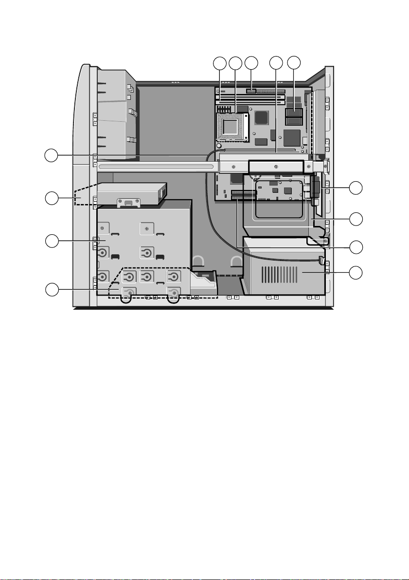
Welcome
5
4
10
9
8
7
6
11
12
3
2
1 Power supply unit (PSU)
2 First or “master” hard disk drive (HDD)
3
Forward drive bay for removable media drives and/or a second HDD
4 Diskette drive
5 Cable for side panel lock sensor
6
DIMM sockets for system memory upgrades
7
Processor socket Zero Insertion Force (ZIF) “Socket 7”
8 Main jumper block
9 Expansion card riser
10
Video memory upgrade sockets (optional)
11
Second serial port (optional)
12
Rear drive bay for SCSI hard disk drives
13 Primary and secondary E-IDE connectors
13
1
1/6 OWNER’S HANDBOOK
Page 18

General advice
This computer is designed to be used in a normal home or office
environment. Here are a few hints for choosing a suitable site:
♦ Place the system unit flat on a sturdy, level surface, free from
♦ Site the computer away from moisture, direct sunlight, and
♦ When positioning the system unit, monitor and keyboard, take
♦ Give the computer plenty of room so that air can circulate on
Welcome
vibration.
extremes of heat and cold. Avoid situations in which the
surrounding temperature or humidity may change rapidly.
When the computer is in use, the temperature should be
between 10 and 35
o
C and humidity between 20% and 80%
(with no condensation).
into account any local or national regulations relating to
ergonomic requirements. For example, you should ensure that
little or no light is reflected off the monitor screen as glare, and
that the keyboard is placed in a comfortable position for
typing.
all sides. Air is drawn into the system unit through vents at the
front, and expelled through the circular vent on the back.
Ensure that these vents are never obstructed.
Do not allow any cables, particularly power cords, to trail across the
floor where people walking past can snag them.
WARNING
The computer uses the system unit AC power cord as its ‘disconnect
device’. Ensure that the system unit is positioned close to the AC power
outlet, and that the plug is easily accessible.
To prevent fire and electric shock, do not expose any part of the system
unit to rain or moisture.
OWNER’S HANDBOOK 1/7
Page 19

Welcome
Connecting the components
Use the following guidance to connect the components together. It
is important that you take each step in the order indicated.
1. Before connecting any components, ensure that the AC power
supply is switched off or disconnected, and that the system
unit, the monitor, and any peripherals are turned off.
2. Connect the components’ signal cables to their respective ports
on the system unit: keyboard, mouse, monitor, audio (where
appropriate) and any other peripherals. Where appropriate,
connect the computer to the network.
3. Connect the various power cords: monitor, system unit and
any other peripherals to nearby, grounded AC power outlets.
Then switch on or connect the AC power supply.
With AC power applied, the system unit is usually in Off [red]
mode. See the Getting Started chapter for more information about
power modes.
Some models incorporate a feature, controlled in BIOS Setup, that
automatically boots the PC to On [green] mode if AC power is
restored, for example, after a power failure. See the on-line help in
BIOS Setup for more information.
1/8 OWNER’S HANDBOOK
Page 20

2 GETTING STARTED
You should read this chapter even if you do not read any other. It
provides important information to help you to use your
Apricot server safely and efficiently.
Turning on the PC
To turn on the computer, simply press the P
colour of the Power Mode indicator turns from [red] to [green].
Remember that the monitor has its own power button or switch; see
the monitor’s User Guide for details.
Power-on self-test (POST)
Whenever the computer is turned on, a power-on self-test (POST)
routine tests various hardware components, and compares the actual
configuration of the computer with that recorded in its permanent
memory. During this time, BIOS sign-on and POST messages may
be displayed. These messages are not significant unless they report
errors – see the BIOS Setup & POST chapter.
Booting the operating system
Provided that POST succeeds without discovering any serious errors
or configuration discrepancies, the computer attempts to find an
operating system; that is, it attempts to ‘boot’.
Apricot PCs are typically supplied with either Windows 95,
Windows NT or MS-DOS/Windows for Workgroups already in
place or ‘pre-installed’ on the hard disk, so that the operating system
is ready for you when you turn on the computer.
NOTE
If a diskette is in the diskette drive when the computer is turned on, the
computer will attempt to boot using that diskette. This will succeed only
if the diskette is a ‘system diskette’; that is, one bearing at least the
rudiments of an operating system.
OWER
button. The
OWNER’S HANDBOOK 2/1
Page 21

Getting Started
Power saving
Use the P
button to turn the computer on and change power
OWER
modes. The colour of the Power Mode indicator shows the current
power mode:
[red] Off. Your computer is turned off, but is still connected
to the AC power supply, ready to be turned on (or turn
itself on) when needed.
[yellow] Suspend. Your computer is “sleeping” to conserve
electricity. The processor stops, the hard disk stops
spinning and the monitor goes blank. Briefly pressing
the P
button wakes it up again. (This mode is
OWER
not available with Windows NT 4.x.)
[green] On or Standby. Your computer is awake and working.
During periods of inactivity the PC automatically
reduces the power consumption of idle components
(Standby mode). For example, the monitor screen may
go blank. Move the mouse or press any keyboard key
to wake up the PC again.
In Suspend mode your computer complies with the requirements of
the “Energy Star” programme for energy-saving systems. In Standby
mode your computer does its best to minimise power usage but may
not always reach Energy Star levels.
If a suitable modem is installed, you can tell the computer to wake
itself up from Suspend or Off mode when an incoming call is
received. A networked computer can also be woken up by remote
control, if it is fitted with a network card that supports IBM’s
“Wake On LAN” technology.
2/2 OWNER’S HANDBOOK
Page 22

Manual power saving
Getting Started
If you press the P
button while the PC is On [green] and
OWER
running either Windows 95 or Windows for Workgroups, the PC
goes into Suspend [yellow] mode.
Alternatively, in Windows 95 (or later) you can click the Start
button in the taskbar, then click Suspend.
You have to press the P
button to return to On [green] mode
OWER
– just moving the mouse or using the keyboard won’t work.
NOTE
Future versions of Windows will allow you to redefine the P
OWER
button so that when you press it the operating system shuts down and the
PC goes directly into Off mode.
Automatic power saving
If you leave your PC running Windows 95 or Windows for
Workgroups without doing anything, it moves automatically
through Standby [green] to Suspend [yellow] mode. Press the
P
button to wake it up again.
OWER
You can turn off Automatic Power Saving in the BIOS Setup
utility; see the BIOS Setup & POST chapter for more information.
CAUTION
The monitor supplied with your computer is designed to recognise these
energy-saving modes. If you want to use another monitor, make sure
that it supports the VESA standard for “Display Power Management
Signalling”; if it doesn’t, it may be permanently damaged.
OWNER’S HANDBOOK 2/3
Page 23

Getting Started
Shutting down the PC
To shut down the computer safely, do the following:
1. Wait until all the activity indicators on the front bezel show
‘not busy’.
2. Turn off any attached peripherals, except for the monitor and
other peripherals that are designed to be kept on permanently.
3. According to your operating system:
◊ In Windows 95 or Windows NT 5.x, click the Start
button in the taskbar, then click Shut Down. Select
Shutdown the computer and click Yes. You do not have to
press the P
◊ In Windows NT 4.x, click the Start button in the taskbar,
then click Shut Down. Select Shutdown the computer and
click Yes. When told that it is safe to do so, press the
OWER
P
◊ In Windows for Workgroups, click the File menu in
Program Manager, then click Exit Windows. Once back in
MS-DOS, press the P
◊ In MS-DOS, or during POST, press the P
button.
OWER
button to turn off the computer.
button.
OWER
OWER
button.
After you shut down the PC, wait at least 5 seconds before turning
it on again. The computer may not initialise itself properly if you
turn it off then on again in quick succession.
Emergency shut down
In exceptional circumstances, you can put your PC into Off [red]
mode without shutting down Windows first. To do this, press and
hold down the P
If you press the P
or performing the power-on self-test (POST), the PC always goes
directly into Off [red] mode.
CAUTION
In an emergency shut down, you may lose any recent changes made to
the files you are currently working on.
2/4 OWNER’S HANDBOOK
button for at least four seconds.
OWER
button while the PC is running MS-DOS
OWER
Page 24

Using the computer for the first time
First time with Windows 95 or Windows NT
The first time you turn on your computer you must tell
Windows your name (and the name of the company for which you
work, if applicable) and agree to the legal terms and conditions of
the Windows Licence Agreement. Windows then spends a few
minutes analysing your computer and configuring itself to take full
advantage of your computer’s components. Windows 95 also offers
you the opportunity to install a printer.
First time with Windows for Workgroups
The first time you turn on your computer a message appears
explaining the legal terms and conditions that govern the use of the
software pre-installed on the computer’s hard disk. Once you have
read this message, you can press the
you are acknowledging that you have read, understood and accepted
the terms and conditions.
F
Getting Started
3 key to continue. By doing so
OWNER’S HANDBOOK 2/5
Page 25

Getting Started
Electronic Fingerprinting
Electronic Fingerprinting allows you to ‘brand’ your computer by
storing personal information in its permanent memory. If you
include your name, address and phone number this will aid the
police if your computer is stolen.
The Apricot Electronic Fingerprinting program appears every time
you start Windows until you have branded the computer. If you
don’t brand your computer promptly, someone else might do it
first.
After you have entered your details you are required to set a
‘branding password’. This password will be requested if you ever
need to run the Electronic Fingerprinting program again to change
the branding information (for example, if you change address).
Optionally, for extra security, you can decide that this same
password is requested every time the computer is turned on, or
every time the AC power supply is interrupted.
If you forget your branding password, you can use a special ‘fallback password’ instead. The fall-back password is a 12-digit number
that is unique to your computer. It is displayed once, the first time
you set a branding password.
If you decide to use the branding password to control access to your
computer, don’t set up “password on boot” in the BIOS Setup
utility as well, or both passwords will be requested every time the
computer is turned on (branding password first, then the supervisor
password).
CAUTION
Do not turn off the computer while using the Electronic Fingerprinting
program. It might corrupt your computer’s BIOS.
IMPORTANT
The fall-back password is displayed only once. You must make a
note of the password immediately, because you will never see it
again. There is a page at the end of this manual where you can
write it down.
2/6 OWNER’S HANDBOOK
Page 26

Backing-up the pre-installed software
Apricot PCs arrive with a pre-installed copy of Windows 95,
Windows NT or Windows for Workgroups. Additional software
may be pre-installed at the factory or by your Mitsubishi Electric
PC supplier.
We strongly recommend that you copy or ‘back-up’ any pre-installed
software soon after setting up the system. This is particularly
important for systems that are supplied without installation
diskettes for the software on the hard disk. A back up copy will
safeguard the pre-installed software against loss if the hard disk fails
or if you accidentally overwrite or delete files.
♦ The Microsoft Create System Disks utility (Windows 95) or
the Apricot Disk Maker utility (Windows NT or Windows for
Workgroups) allows you to create installation diskettes from
disk images pre-installed on the hard disk.
♦ To back up other pre-installed software (and your own files)
use the Backup tool (Windows 95 and Windows NT) or
Backup for Windows (Windows for Workgroups).
In general, any copy you make of pre-installed software must be
used only as a back-up copy, in case the pre-installed version is lost.
You are not allowed to use installation diskettes created from disk
images to install the software onto another computer.
Getting Started
Improving your display settings
Your pre-installed copy of Windows is configured for a standard
monitor setting (640 x 480 pixels in a maximum of 16 different
colours), so that Windows is sure to display correctly whatever
monitor you have.
Most modern monitors, including Mitsubishi Electric monitors, can
display higher resolutions than standard VGA. You can change the
setting to one that more closely matches your own monitor, to get
the best performance from it.
OWNER’S HANDBOOK 2/7
Page 27

Getting Started
Display settings in Windows 95 or Windows NT
The monitor setting is changed by using the Settings tab of the
Display Properties dialog. See Windows
Help for instructions on
’
changing display settings.
TIP
To view the Display Properties dialog, right-click with the mouse while
pointing at the background area of the Windows desktop, then select
Properties from the pop-up menu.
Display settings in Windows for Workgroups
The monitor setting is changed by using the ATI Desktop utility in
the Apricot group. Open ATI Desktop, choose Screen Adjustment,
then choose Select Monitor. This offers a list of all current Apricot
monitors. Once you have selected the correct monitor, you can
select the required resolution. See ATI Desktop’s on-line help for
more information.
If your hard disk is larger than 2 gigabytes
If your Apricot PC is pre-installed with Windows 95, the entire
hard disk is initially formatted as one partition.
If you have Windows NT, the first 2 Gbytes are formatted (using
FAT) as a primary partition. The rest of the disk is untouched. You
can repartition and reformat the disk using the Disk Administrator
tool in the Administrative Tools (Common) folder.
If you have Windows for Workgroups, the first 2 Gbytes are
formatted as the primary partition. The remainder of the disk is
divided into formatted partitions of no more than 2 Gbytes and no
less than 512 Mbytes.
2/8 OWNER’S HANDBOOK
Page 28

3 REMOVABLE MEDIA DRIVES
COMPACT
Diskette drive
Your Apricot Server is fitted with a 1.44 Mbyte diskette drive. This
accepts either 1.44 Mbyte (HD) or 720 Kbyte (DD) diskettes.
Each diskette has a rigid plastic cover, with a metal shutter that
guards the disk surface. Never touch the exposed surface under the
shutter – you could deform the disk or leave a fingerprint that
might make the diskette difficult to read.
Inserting a diskette
1. Insert the diskette with the metal shutter foremost, and with
the label side facing upwards.
drive’s
EJECT
button pops out slightly. The drive flap stays
2. Push the diskette all the way in until it ‘clicks’ into place. The
open, leaving the diskette just visible.
OWNER’S HANDBOOK 3/1
Page 29

Removable media drives
Ejecting a diskette
♦ Wait until the drive’s activity indicator is unlit, then press the
button.
EJECT
If a diskette becomes stuck in the drive, perhaps because its label has
peeled back, do not attempt to remove it with tweezers or any
similar implement; you risk damaging the drive. Call an authorised
maintainer.
Write-protecting a diskette
♦ A diskette can be write-protected by sliding a tab towards the
edge of the diskette to expose the small hole beneath it (see
illustration).
You can read, copy or print the files on a write-protected diskette,
but you cannot create, rename or delete any files.
Diskette care
Keep diskettes away from dust, moisture, magnetic objects, and
equipment that generates magnetic fields. Also, avoid extremes of
temperature and exposure to direct sunlight. Otherwise, data
recorded on the diskette may become corrupted.
Always check that labels are firmly fixed before you use the diskette
and do not leave them in the drive for prolonged periods.
3/2 OWNER’S HANDBOOK
Page 30

CD-ROM drive
The CD-ROM drive can retrieve multimedia data from CD-ROM
discs and multi-session Photo-CD discs. It can also play normal
music CDs (the drive has its own headphone jack and associated
volume control).
Do not attempt to move the computer while a CD is in the drive,
especially if the CD is being played at the time.
Removable media drives
1
COMPACT
5
4
3
2
1
CD-ROM disc drawer (platter)
2 Headphone jack & volume control
3
Activity indicator (amber = busy)
4 CD emergency eject hole
5
JECT
button (doesn’t work while PC is turned off)
E
WARNING
The laser beam inside the CD-ROM drive is harmful to the eyes if
looked at directly. Do not attempt to disassemble the CD-ROM drive. If
a fault occurs, call an authorised maintainer.
OWNER’S HANDBOOK 3/3
Page 31

Removable media drives
Inserting a compact disc
1. Press the
button on the front of drive.
EJECT
2. Place the CD centrally, printed side up, on the platter.
3. Push the
button again, or gently push the front of the
EJECT
platter to draw it back into the drive.
PACT
COM
Ejecting a compact disc
♦ Ensure that the drive’s activity indicator is not showing ‘busy’,
then press the
To eject the platter manually (for example, during a power failure)
you must first ensure that the computer is completely off (the Power
Mode indicator will be unlit). Insert a thin metal rod (such as an
unwound paper clip) into the emergency eject hole. Push carefully
and firmly.
Care of CDs
Keep CDs well away from dust and moisture, and avoid touching
the surface of the CD. Avoid extremes of temperature and exposure
to direct sunlight as these may cause the disk to warp. Always store
them in their original container.
3/4 OWNER’S HANDBOOK
EJECT
button.
Page 32

DAT tape drive (option)
COMPACT
1
2
4
3
It is recommended to regularly make a backup of the software on
the system hard drives. A DAT tape drive is one of the simplest and
most convenient methods. The drive can be obtained from your
supplier as an upgrade kit. A brief installation guide is give in the
chapter, ‘Drive upgrades’.
Operating system software can be easily reinstalled from the master
software disks or CD-ROMs, but created data from a multitude of
server users can not be easily replaced. The common backup
method is to use two or three tapes in rotation, either weekly, daily
or even twice daily for large organisations with complex networking.
Removable media drives
1 Tape cassette entry slot
2
Cassette engaged (green)
3
Drive active (amber)
4 Cassette eject button
The LEDs may show different colours dependant on the drive
activity. For full information see the separate ‘User’s Guide’ for the
drive.
OWNER’S HANDBOOK 3/5
Page 33

Removable media drives
Inserting a DAT tape
Hold the cassette with its metal plate downward and the open tape
edge towards the computer. Without using undue force, press the
cassette against the drive tape slot. The dust cover will swing open
allowing the tape cassette to enter. Push firmly home. With some
models of drive, the cassette does not enter the drive completely.
The ‘Cassette engaged’ green light should come on.
COMPACT
Removing a DAT tape
Wait until the drive active light goes out and all activity has ceased,
then press the Eject button. The cassette will move outwards and is
easily lifted clear.
Care of DAT cassettes
Always store cassettes in their original dust tight cases. Keep them
away from dust, moisture, magnetic objects, and equipment that
generates magnetic fields (such as telephones or monitors). Avoid
extremes of temperature and exposure to direct sunlight. Regularly
check your backup tapes for wear or damage.
3/6 OWNER’S HANDBOOK
Page 34

4 EXPANSION CARDS
Expansion cards (also known as expansion boards, controllers or
adapters) are small self-contained circuit boards which extend the
capabilities of the computer. For example, a graphics card could
provide more specialised video functions than those offered by the
on-board video system, or a modem card could provide a
connection to the Internet via a telephone line.
Your computer can accept two basic types of expansion card:
♦ ISA or Industry Standard Architecture cards
♦ PCI or Peripheral Component Interconnect cards
You don’t need to understand what these terms mean, but before
adding a card to your computer you will need to know whether it is
ISA or PCI and possibly its physical dimensions.
The following diagram shows the layout of the six expansion slots in
your server.
1
2
3
1 Two PCI slots, full-length
2 PCI/ISA slot, full-length
3 Three ISA slots, full-length
10101
OWNER’S HANDBOOK 4/1
Page 35

Expansion Cards
Configuring the card
Part of the installation procedure for an expansion card involves
setting up or “configuring” the card so it will work correctly in the
computer.
Most modern PCI cards employ a feature called “Plug and Play”
(PnP). This allows Windows 95 – and other PnP-aware operating
systems – to configure the card automatically the first time you turn
on the computer after installing the card.
However, many ISA cards (and some PCI cards) require manual
configuration. If manual configuration is required, you will
probably need to specify at least two of the following:
♦ Interrupt request level (IRQ)
♦ Direct memory access (DMA) channel
♦ Base input/output (I/O) port address
♦ Base memory address
The important thing to understand is that the settings of the card
you are installing must be different from the settings used by other
cards already in the computer or by components on the computer’s
motherboard. In other words, the settings must not “conflict”.
The documentation accompanying the card should tell you whether
the card supports Plug and Play, or if not, how to configure it.
Remember to check any diskettes supplied with the card for
README or other help files.
Some cards require you to move jumpers or set switches on the card
to configure them. This is best done before installing the card in the
computer. Other cards can be configured by running a
configuration program after installing the card. Some cards use a
mixture of both methods.
Cards often come with pre-configured or default settings. It is best
to rely on these settings as much as possible, and change them only
if they conflict with other devices.
4/2 OWNER’S HANDBOOK
Page 36

Expansion Cards
ISA Interrupt request level (IRQ)
The “interrupt request level” or “IRQ” is the means by which the
expansion card sends a signal to get the attention of, or interrupt,
the processor. Your PC has interrupt levels numbered IRQ0 to
IRQ15, many of which are needed for components on the
computer’s motherboard. There are two ways round this.
♦ You can disable certain motherboard components either by
means of the BIOS Setup utility or else by changing jumper
settings on the motherboard. This frees the resources used by
those components.
♦ The audio system, USB controller and standard input/output
controller (e.g., for serial and parallel ports) are Plug and Play
(PnP) devices. If you use BIOS Setup or Windows 95 Control
Panel to exclude or reserve an interrupt that is usually assigned
to one of these devices an alternative interrupt will be assigned
though Plug and Play and the original interrupt can instead be
used by the expansion card.
See the BIOS Setup & POST chapter for more information about
BIOS Setup. See the Motherboard Features & Upgrades chapter for
more information about jumper settings and the usual assignment
of interrupts to motherboard components.
Direct memory access (DMA) channel
Some hardware devices can use a “DMA channel” to access system
memory without directly burdening the processor. Your PC has
DMA channels numbered DMA0 to DMA7. As with interrupts,
you can use vacant channels or re-assign existing ones.
See the Motherboard Features & Upgrades chapter for more
information about the usual assignment of DMA channels.
Base input/output (I/O) port address
I/O ports are used by the processor to communicate with hardware
devices. Each port appears to the processor as an address low down
in its address space. Some expansion cards are also controlled by I/O
ports. The “base I/O port address” specifies where the card’s ports
begin.
OWNER’S HANDBOOK 4/3
Page 37

Expansion Cards
Base memory address
Some expansion cards are fitted with memory of their own, usually
read-only memory (ROM) containing functional extensions to the
computer’s BIOS (basic input/output system) ROM. Some cards
also have random-access memory (RAM).
In order that this memory can be recognised by the system
processor, it must be mapped somewhere within the computer’s
own address space. By setting the “base memory address” you
specify where the card’s memory begins within the address space.
Typically, an expansion card’s memory must be mapped onto the
addresses between C8000h and DFFFFh – an area known as the
upper memory block or UMB. You can exclude or reserve UMB
regions with the BIOS Setup utility.
The card’s documentation should list its possible base memory
addresses. You may also need to know how much memory the card
has, so that you can leave the right gap between this card’s base
address and the next.
More about memory addresses
Memory addresses are always written in base 16 or “hexadecimal”
notation. Unlike the ten digits of the decimal system (0-9),
hexadecimal uses sixteen digits (0-9 and A-F, where A=10, B=11,
C=12 and so on up to F=15).
Hexadecimal numbers are denoted either by the suffix “h” or by the
prefix “0x”. The final digit of a five-digit memory address is often
omitted, so C8000h may be written as C800h.
Because amounts of memory are usually stated as kilobytes (Kbytes)
rather than in hexadecimal notation, the following conversion table
may be helpful:
4 Kbytes = 1000h 32 Kbytes = 8000h
8 Kbytes = 2000h 64 Kbytes = 10000h
16 Kbytes = 4000h 128 Kbytes = 20000h
4/4 OWNER’S HANDBOOK
Page 38

Installing the card
Read all these instructions through before attempting to install any
expansion card.
WARNING
Never carry out any work inside the computer with AC power applied.
Always shut down the computer and unplug all power cords before
removing the top cover.
IMPORTANT
This system complies with the CE Marking Directive and its strict legal
requirements. Use only parts tested and approved by Mitsubishi Electric
PC Division. Failure to do so may result in invalidating both the
compliance and your warranty. All expansion cards, drives and
peripherals must carry the CE mark to ensure continued compliance.
The only tool required is a small cross-head screwdriver.
1. Turn off the computer and unplug all power cords.
2. Take suitable anti-static precautions and remove the righthand side and top panels. For more information see “Antistatic precautions” in the Safety & Regulatory Notices at the start
of this manual.
Expansion Cards
3. Decide in which of the available slots you wish to install the
card, according to its type and size. In general it is easiest,
where possible, to start with the farthest slot and work
forwards.
4. Remove the slot’s blanking plate by removing the securing
screw. Keep the screw; it will be needed later to secure the
card.
5. If the card you are installing is configured by the means of
jumpers or switches, check that it is correctly configured before
proceeding.
6. When installing a card that uses the VESA/AMC video feature
connector on the motherboard, it is best to plug the video
OWNER’S HANDBOOK 4/5
Page 39

Expansion Cards
feature cable into the motherboard before you install the card;
otherwise, the card may get in the way of the connector. See
the Motherboard Features & Upgrades chapter to locate the
VESA/AMC connector.
CAUTION
Be careful how you use this connector. Some pins carry +5 V power
which could damage the expansion card if it is incorrectly attached.
7. Position the expansion card alongside the slot in which you
wish to install it. Align the rear of the card with the slot in the
rear of the system unit, and, if the card is full length, align the
front of the card with the card guide.
8. Slide the card into the slot ensuring that the card edge
connector engages correctly with the socket on the riser board.
Do not use excessive force.
9. Secure the card by replacing the screw that you removed in
Step 4.
10. Connect any necessary signal cables to the card.
11. Ensure no other cables or connectors have become dislodged,
then replace the side and top panels.
4/6 OWNER’S HANDBOOK
Page 40

Reserving ISA legacy resources
If the computer does not automatically detect the new expansion
card the first time you turn it on, start the BIOS Setup utility, go to
the Advanced menu and change the Reset Configuration Data item
to “Yes”.
If you have just installed an ISA card, you may also need to reserve
or exclude the legacy resources (that is, the interrupts and UMB
regions) used by the card. This is necessary so that any Plug and
Play components can be configured automatically and won’t try to
use the same settings. See the BIOS Setup & POST chapter for more
information.
Alternatively, you can use the Windows 95 Control Panel to change
the resource settings used by devices:
1. Click the Start button in the taskbar, then Settings, then
Control Panel.
2. Double-click on System, then click the Device Manager tab of
the System Properties dialog.
3. Select the device whose resources you want to change, then
click Properties.
Expansion Cards
4. Click the Resources tab of the device’s Properties dialog.
If your device does not have a Resources tab, either you cannot
change its resources or it isn't using any resource settings.
5. Click the resource you want to change, un-check the Use
Automatic Settings box, then click Change Setting.
TIP
In some cases, you may see a Set Configuration Manually button on
the Resources tab. You may have to click this button before you can
change resource settings.
OWNER’S HANDBOOK 4/7
Page 41

Expansion Cards
Telling Windows about the new hardware
Windows 95 and Windows NT 4.x (or later) should automatically
detect and configure cards that support “Plug and Play”. In other
cases you may have to tell Windows that you have installed new
hardware, as follows:
1. Click the Start button in the taskbar, then Settings, then
Control Panel.
2. Double-click on Add New Hardware.
3. Follow the instructions in the Add New Hardware Wizard.
4/8 OWNER’S HANDBOOK
Page 42

5 MOTHERBOARD FEATURES
AND UPGRADES
This chapter describes the features of the computer motherboard
and gives step-by-step instructions for adding more system or video
memory, upgrading the processor, and replacing the configuration
battery. Details of all relevant motherboard connectors and jumper
settings are included.
The Welcome chapter tells you how to remove the system unit
panels. See the section on “Anti-static precautions” in the Safety &
Regulatory Notices at the beginning of this manual for advice on how
to avoid damaging your computer with static electricity.
WARNING
Never carry out any work inside the computer with AC power applied.
Always shut down the computer and unplug all power cords before
removing the top cover.
CAUTION
Do not alter any jumpers or switch settings other than those identified
here, unless told to by your Mitsubishi Electric PC supplier or an
authorised maintainer. Otherwise, you may damage the system
processor, the motherboard, or both.
NOTE
After you have upgraded the computer, it may not at first recognise the
new configuration. Start the BIOS Setup utility, go to the Advanced
menu and change the Reset Configuration Data item to “Yes”, then
restart the computer.
OWNER’S HANDBOOK 5/1
Page 43

Motherboard Features & Upgrades
Motherboard features
PL19
Video
1
2
3
4
5
6
PL 202
Parallel Com 1
PL 18
USB
(optional)
7
8
Mouse
Key/Bd
9
Out
In
10
1 Video memory sockets 11 Secondary E-IDE connector
2 Motherboard power connector 12 Primary E-IDE connector
3 VESA/AMC feature connector 13 CMOS battery
4 PSU logic connector 14 “Wake on LAN” connector
5 DIMM sockets 15 1.44 Mb diskette drive connector
6 Processor fan-sink connector 16 Second serial port connector
7 Processor ZIF socket 17 Modem audio connector
8 Riser board connector 18 CD audio connector
9 Internal speaker connector
10 Front panel connector
Pins 1-2 Power button
Pins 3-4 HD indicator light
Pins 5-6 Unused
Pins 7-8 Power Mode light
18
17
16
15
14
PL11
PL4
PL3
13
12
11
PL201
5/2 OWNER’S HANDBOOK
Page 44

Motherboard Features & Upgrades
PL19
PL 18
Motherboard jumper settings
There are only a few jumpers on the motherboard that you may
need to alter. All others are set at the factory and should not be
changed.
On the motherboard, pin 1 of each jumper block is indicated by a
small triangular marking.
Processor voltage and bus speed (PL19, PL18)
CAUTION
Do not change these jumpers unless you have upgraded the processor. If
they are set incorrectly the processor and other vital motherboard
components could be destroyed.
The BF0 and BF1 jumpers on jumper block PL19 may be fitted in
the High (“1”) or Low (“0”) position; the FS, PW2, PW1 and
PW0 jumpers may simply be either fitted across both pins (“In”) or
not (“Out”). See the table on the next page for the correct
configurations.
For Pentium processors only, two jumpers must also be fitted on
PL18. These jumpers must not be fitted for Pentium/MMX
processors.
OWNERS HANDBOOK 5/3
Page 45

Motherboard Features & Upgrades
Processor Speed Jumper block PL19
BF1 BF0 FS PW2 PW1 PW0
Pentium 90 MHz High High In In In In
Pentium 100 MHz High High Out In In In
Pentium 120 MHz High Low In In In In
Pentium 133 MHz High Low Out In In In
Pentium 150 MHz Low Low In In In In
Pentium 166 MHz Low Low Out In In In
Pentium 200 MHz Low High Out In In In
Pentium/MMX 166 MHz Low Low Out Out Out Out
Pentium/MMX 200 MHz Low High Out Out Out Out
Pentium/MMX 233 MHz High High Out Out Out Out
On-board video disabling (PL19)
If you install a video adapter expansion card, the computer should
automatically detect this and disable the on-board video adapter. If
for some reason this does not happen, and you experience problems
with a newly-fitted card, you can manually disable the on-board
video adapter by removing the VGA jumper from jumper block
PL19.
Audio disabling (PL19)
The on-board audio system can be disabled by removing the AUD
jumper from jumper block PL19. Disabling the audio system frees
the interrupt and DMA channel used by that system (normally
IRQ5 and DMA1).
5/4 OWNER’S HANDBOOK
Page 46

Motherboard Features & Upgrades
BIOS upgrade and recovery (PL11, PL3)
These jumpers should not normally be changed except by a service
engineer or at the direction of a service engineer.
CMOS is cleared by moving the PL11 jumper to the 2-3 position
for a few moments while the system is turned off, then returning it
to the normal 1-2 position.
You must ensure that BIOS reprogramming is enabled if you want
to use Electronic Fingerprinting or the optional Apricot LS Security
Card (LOC Technology).
Clearing CMOS PL11
CMOS battery connected (default) 1-2
CMOS battery disconnected 2-3
BIOS reprogramming PL3
Enabled (default) 1-2 (
Disabled 2-3 (
Power Mode light colour (PL201)
Normally, the Power Mode light is [red] when the system is in Off
mode. If you move the jumper on block PL201 to pins 2-3 (
the light is extinguished in Off mode.
PROG
)
DIS
)
)
OFF
OWNERS HANDBOOK 5/5
Page 47

Motherboard Features & Upgrades
Motherboard IRQs and DMA channels
Components Interrupts (IRQs)
0 1 2 3 4 5 6 7 8 9 101112131415
System timer
Keyboard controller
PIC daisy chain
Serial port 2
Serial port 1
Audio
Diskette controller
Parallel port
Real time clock
On-board video
USB
Mouse
Co-processor
Primary E-IDE
Secondary E-IDE
BS
BS
JS
BS
BS
JS
BS
BS
BS
BS
Components DMA channels
01234567
Audio
Diskette controller
Parallel port (ECP)
DMAC daisy chain
Fixed assignment Usual assignment BIOS alternative PnP alternative
BS = Can be disabled by BIOS Setup JS = Can be disabled by moving a jumper
5/6 OWNER’S HANDBOOK
JS
BS
BS
Page 48

Motherboard Features & Upgrades
Adding more memory
You can give your PC more memory by adding or replacing
memory modules called “DIMMs”.
The motherboard’s two DIMM sockets accept DIMMs of up to
128 Mbytes in any combination (giving a maximum memory
capacity of 256 Mbytes).
IMPORTANT
The DIMMs you use must have the following specification: gold
contacts, 3.3V, 64-bit, unbuffered, either SDRAM-type with Serial
Presence Detect (SPD) and a CAS latency of 2 at 66 MHz or else
EDO-type with 60 ns timing. If you use any other type of DIMM you
risk damaging the motherboard.
Fitting and removing DIMMs
Before you begin
1. Turn off the computer and unplug all power cords.
2. Take suitable anti-static precautions and remove the righthand side and top panels. For more information see the section
on “Anti-static precautions” in the Safety & Regulatory Notices
at the start of this manual.
3. Remove any expansion cards that impede access to the DIMM
sockets.
4. Lay the system unit on its side.
To install a DIMM
1. Take the DIMM out of its anti-static packaging. Hold it by its
ends and avoid touching the metal contacts.
2. Align the DIMM with the chosen socket, ensuring that the
socket end clips are not obstructing.
◊ The indents along the connector edge are asymmetrical to
prevent the DIMM being fitted into the socket the wrong
way round.
OWNERS HANDBOOK 5/7
Page 49

Motherboard Features & Upgrades
3. Pushing gently on its top corners, press the DIMM into the
socket and make sure the two end clips snap into place. Do not
use excessive force. If the module will not fit easily, remove it
and start again.
To remove a DIMM
1. Press the tabs on both of the socket’s end clips at the same
time. This will release the DIMM and lift it partly out of the
socket.
2. Pull the DIMM clear of the socket. Hold the DIMM by its
ends and avoid touching the metal contacts.
3. Place the DIMM in suitable anti-static packaging.
When you have finished, replace any expansion cards you needed to
remove, then refit the system unit panels.
If the computer does not automatically detect the new memory the
first time you turn it on, start the BIOS Setup utility, go to the
Advanced menu and change the Reset Configuration Data item to
“Yes”, then restart the computer. If an error message appears, check
that the DIMMs are of the correct type and are seated correctly in
their sockets.
5/8 OWNER’S HANDBOOK
Page 50

Motherboard Features & Upgrades
Adding more video memory
Video memory is memory reserved for use by the on-board video
controller. More video memory can provide more colours or higher
resolutions to an extent determined by the capabilities of your
monitor.
If your computer has 1 Mbyte of video memory, you can upgrade it
to the maximum of 2 Mbytes.
To add video memory
1. Turn off the computer and unplug all power cords.
2. Take suitable anti-static precautions and remove the righthand side and top panels. For more information see the “Antistatic precautions” section in the Safety & Regulatory Notices at
the start of this manual.
3. Remove any expansion cards that impede access to the video
memory upgrade sockets (see the diagram at the start of this
chapter).
4. Lay the system unit on its side.
5. Unpack the upgrade kit and lay the memory chips out on an
anti-static surface. Hold each chip by its edges and be careful
not to touch the metal pins.
6. One by one, insert the chips in the sockets.
◊ It is important that the chips are fitted the right way
round. Some chips have a single bevelled edge at one end.
Others have a small semicircular notch at one end and a
bevel at one corner. In either case, the bevelled or notched
end must be aligned with the bevelled corner on the socket
itself.
7. Replace any expansion cards you removed earlier and refit the
system unit panels.
If the computer does not automatically detect the new memory the
first time you turn it on, start the BIOS Setup utility, go to the
Advanced menu and change the Reset Configuration Data item to
“Yes”, then restart the computer.
OWNERS HANDBOOK 5/9
Page 51

Motherboard Features & Upgrades
Upgrading the processor
The ZIF (zero insertion force) “Socket 7” processor socket on the
motherboard is designed to accept a variety of processors (see the
table earlier in this chapter). You may wish to upgrade your
processor by replacing it with one of higher performance.
Read the following instructions carefully before starting work.
Changing the processor
1. Turn off the computer and unplug all power cords.
2. Take suitable anti-static precautions and remove the righthand side and top panels. For more information see the “Antistatic precautions” section in the Safety & Regulatory Notices at
the start of this manual.
3. Remove any expansion cards that impede access to the
processor.
4. Lay the system unit on its side.
5. If the system was in use immediately before starting this
procedure, the processor will be hot; wait at least 15 minutes
for it to cool down.
WARNING
The processor, its fan-sink (combined fan and heat sink), and some of its
neighbouring components can get very hot. You may burn your fingers if
you attempt to remove the processor before it has cooled down.
6. Unplug the power cable of the processor’s fan-sink from the
motherboard. Note where the cable plugs in because you will
need to re-attach it later.
7. Unclip the fan-sink’s retention clip from the ZIF socket at the
front and the back.
8. Release the lever from the side of the ZIF socket and raise it to
the upright position (at right-angles to the motherboard).
There may be a little stiffness at the beginning and end of the
lever’s movement; be careful not to use excessive force.
5/10 OWNER’S HANDBOOK
Page 52

Motherboard Features & Upgrades
9. Lift the processor (with fan-sink) clear of the system unit and
place it on an anti-static surface. Hold the processor by its
edges and avoid touching any of the metal pins.
10. Separate the fan-sink from the processor by twisting the fansink from side to side to loosen the grip of the thermal
bonding compound, then slide the fan-sink off to one side of
the processor.
WARNING
When you remove the fan-sink there will be a residual deposit of
thermal bonding compound on the bottom of the fan-sink and the top of
the processor. This compound can cause skin irritation and stain
clothing. Avoid prolonged or repeated contact with skin. Wash your
hands thoroughly with soap and water after handling. Avoid contact
with eyes and inhalation of fumes. Do not ingest.
11. If you are replacing a Pentium processor with a
Pentium/MMX processor, you must remove the two jumpers
from jumper block PL18 (next to the socket). Use the
illustration at the start of this chapter to locate this jumper
block.
12. Ensure that the securing lever on the ZIF socket is still in the
upright position.
13. Take the upgrade processor out of its anti-static packaging.
Hold the processor by its edges and avoid touching the metal
pins.
◊ The upgrade processor and the ZIF socket are keyed to
ensure that the processor is installed in the correct
orientation. (The pin pattern is totally different at one
corner.) It will only fit into the socket one way.
14. Place the processor in the socket, making sure that it is
correctly aligned and that you do not bend or otherwise
damage the pins.
◊ If the processor is not big enough to occupy the entire
socket it should be positioned centrally.
OWNERS HANDBOOK 5/11
Page 53

Motherboard Features & Upgrades
2
1
19a
2
1
CAUTION
If the processor is misaligned it will not go into the socket, and any
attempt to force it will damage the processor, the socket or both.
15. Move the securing lever to the locked position. Apply just
enough pressure to overcome the resistance offered by the
lever.
16. Reposition the fan-sink on top of the new processor.
◊ You may have either of two different types of fan-sink.
Note that the larger fan-sink overhangs the socket at one
side.
17. Re-fasten the fan-sink’s retention clip to the front and back of
the ZIF socket.
5/12 OWNER’S HANDBOOK
Page 54

Motherboard Features & Upgrades
18. Reconnect the fan-sink’s power cable to the motherboard. It
goes on the connector labelled FAN 2 or PL200.
FAN 1
FAN 2
OWNERS HANDBOOK 5/13
Page 55

Motherboard Features & Upgrades
CAUTION
If the fan-sink power cable is not reconnected properly the processor may
overheat and be permanently damaged.
19. Adjust the processor voltage and bus speed selection jumpers
in block PL19 as described at the start of this chapter.
When you have finished, replace any expansion cards you needed to
remove, then refit the system unit panels.
Replacing the configuration battery
The computer keeps a record of its current hardware configuration
in a CMOS memory chip which is sustained by a small battery.
This battery has a life of up to 5 years. If you find that you have to
reconfigure the computer every time you turn it on, the battery is
probably failing and needs to be replaced.
The battery is a 3 volt lithium type (CR2032 or equivalent)
typically used in calculators and other small, battery-powered
electronic items.
To replace the battery
1. Turn off the computer and unplug all power cords.
2. Take suitable anti-static precautions and remove the righthand side and top panels. For more information see the section
on “Anti-static precautions” in the Safety & Regulatory Notices
at the start of this manual.
3. Lay the system unit on its side.
4. Remove the two screws that secure the rear drive bay to the
chassis and take the bay out of the system unit.
5. Using a non-conductive implement, release the latch that
holds the battery in place. The battery will pop up allowing
you to lift it out of the holder.
5/14 OWNER’S HANDBOOK
Page 56

Motherboard Features & Upgrades
WARNING
You must not use a metal or other conductive implement to remove the
battery. If a short-circuit is accidentally made between the battery’s
positive and negative terminals, the battery may explode.
6. Check that the replacement battery looks the same as the
battery you have removed.
7. Taking care not to touch the top or bottom surface of the
battery, pick up the replacement with the positive (+) terminal
upwards. Press the battery into the holder using a nonconductive implement.
8. Refit the rear drive bay and the system unit panels.
9. Dispose of the discharged battery in accordance with the
battery manufacturer’s instructions.
The next time you turn on the computer you will have to run the
BIOS Setup utility to reset the hardware configuration.
OWNERS HANDBOOK 5/15
Page 57

6 DRIVE UPGRADES
This chapter describes how to add further drives to your computer.
♦ The forward drive bay can accommodate two hard disk drives.
Either drive may be of 3.5-inch or 5.25-inch form factor.
These may be E-IDE drives, or SCSI drives if you have a SCSI
host bus adaptor expansion card.
The bay below the CD-ROM drive can accommodate any
♦
5.25-inch peripheral drive, such as the optional DAT drive
shown in the chapter, ‘Removable media drives’.
♦ The rear drive bay is designed to accommodate one or two
more 3.5-inch SCSI drives.
Although it is theoretically possible to mix E-IDE and SCSI drives
within the same system, in practice this is deprecated. The
maximum configurations are therefore two E-IDE drives or four
SCSI drives.
4
3
2
1
1 First or “master” hard disk drive (HDD)
2 Slot for a second hard disk drive
3 Slot for a removable-media drive
4 Rear drive bay for two SCSI hard disk drives
OWNER’S HANDBOOK 6/1
Page 58

Drive Upgrades
MASTER
023
SLAVE
WARNING
Never carry out any work inside the computer with AC power applied.
Always shut down the computer and unplug all power cords before
removing the top cover.
Configuring a Hard Disk Drive (HDD)
HDDs typically require configuration, perhaps by altering jumpers
on the drive itself, prior to installation. Configuration details vary
from drive to drive: a second E-IDE hard disk drive needs to be
configured as the slave drive; a SCSI drive must be configured with
a device ID number, indicating its logical position on the SCSI bus
(the boot SCSI drive is usually drive ‘0’). Most drives are supplied
with documentation describing how to configure the drive. If you
are uncertain about configuring the drive consult your supplier.
IDE drive
A typical E-IDE drive, shown below, is configured as master or slave
by the position of a jumper on the drive.
SCSI drive
The first SCSI drive is usually set at ID ‘0’, additional SCSI hard
drives would then, conventionally, be numbered in sequence, i.e., a
second drive would have an ID of ‘1’ and so on.
A SCSI bus must also have a termination at the end for correct
operation. This is done with a link on the last drive. An existing
drive will probably have the bus termination link set to ‘on’ and this
will have to be changed. The very last drive in the system must be
the only one set for bus termination.
6/2 OWNER’S HANDBOOK
Page 59

Installing in the forward drive bay
To install a second (slave) hard disk drive in the forward drive bay:
1. Turn off the computer and unplug all power cords.
2. If there is a diskette in the diskette drive, remove it.
3. Take suitable anti-static precautions and remove all the system
panels. For more information see “Anti-static precautions” in
the Safety & Regulatory Notices at the start of this manual.
4. Carefully remove the plastic bezel blanking insert from the
lowest front drive slot by pushing it out from the rear with a
blunt instrument (for example, the end of a rubber-tipped
pencil). A hole for this is provided inside the system unit,
alongside the drive bay.
5. Pull out the metal blanking plate from the front of the internal
drive bay metalwork.
6. Remove the 3.5-inch drive mounting plate (it is secured by
two screws on each side).
7. If you are fitting a 3.25-inch hard disk drive, attach it to the
3.5-inch drive mounting plate using the special screws provided
with the drive. Carefully slide the mounting tray (with drive)
back into the drive bay from the front, then secure it on both
sides using the screws you removed at Step 6.
Drive Upgrades
8. Attach a spare power cable to the new drive (it does not matter
greatly which of the available power cables you choose).
9. If you are fitting an E-IDE drive, attach the spare connector on
the HDD ribbon (signal) cable to the slave drive. (The HDD
ribbon cable has two connectors on it; one for the master drive
and one for the slave drive.)
◊ If you are fitting a SCSI drive, attach a spare connector on
the SCSI ribbon (signal) cable to the slave drive.
10. Check to ensure that no other cables or connections have
become dislodged or trapped during the work, then refit the
internal metal blanking plate, the plastic front bezel and the
system unit panels.
OWNER’S HANDBOOK 6/3
Page 60

Drive Upgrades
Installing in the rear drive bay
The rear drive bay is intended for 3.5-inch SCSI hard disk drives.
1. Turn off the computer and unplug all power cords.
2. If there is a diskette in the diskette drive, remove it.
3. Take suitable anti-static precautions and remove the system
side panel. For more information see “Anti-static precautions”
in the Safety & Regulatory Notices at the start of this manual.
4. If the rear drive bay already contains a SCSI drive, unplug the
SCSI ribbon (signal) cable and power cable from that drive.
5. Remove the two screws that secure the rear drive bay to the
chassis and take the bay out of the system unit.
6. Mount the new drive within the bay using the special screws
provided with the drive. The first drive in the bay must be
secured by its base, the second drive must be secured by its
sides.
7. Return the rear drive bay to the system unit and secure it in
place using the screws you removed at Step 5.
8. Attach SCSI ribbon cables and spare power cables to the drives
(it does not matter greatly which of the available power cables
you choose).
9. Check to ensure that no other cables or connections have
become dislodged or trapped during the work, then refit the
system unit panel.
Partitioning and formatting the drive
If the computer does not automatically detect the new hard disk
drive the first time you turn it on, start the BIOS Setup utility, go
to the Advanced menu and change the Reset Configuration Data
item to “Yes”, then restart the computer.
The new drive will initially be blank. Before you can use the drive,
you must partition and format it.
6/4 OWNER’S HANDBOOK
Page 61

Drive Upgrades
Windows 95
Use the MS-DOS Fdisk program to create partitions on the disk.
The Fdisk program can be run in an MS-DOS window within
Windows. Type Help Fdisk at the MS-DOS command prompt to
find out more. After using Fdisk, you are prompted to restart the
computer. Once back in Windows, you can format the partitions by
opening the My Computer folder, selecting the new Drive icon and
choosing the Format command from the File menu.
CAUTION
When you run Fdisk, it assumes that you want to work with the first, or
master, drive (it says the
Current fixed disk drive
switch attention to the slave drive, choose
disk drive
Windows NT
(option 5) from the main menu.
Select next fixed
is 1). To
Use the Disk Administrator tool in the Administrative Tools
(Common) folder. This both creates partitions and formats them.
Windows for Workgroups
Use the MS-DOS Fdisk program to partition the disk followed by
the MS-DOS Format command to format the partitions. Use the
MS-DOS Help command to find out more about Fdisk and
Format. See your MS-DOS documentation for instructions on
using MS-DOS Help.
A limitation of Windows for Workgroups is that each partition can
be no more than 2 gigabytes in size.
OWNER’S HANDBOOK 6/5
Page 62

Drive Upgrades
Configuring the removable media drive
Removable-media drives sometimes require configuration, perhaps
by altering jumpers on the drive itself, prior to installation.
Configuration details vary from drive to drive: a second ATA drive
needs to be configured as a slave drive, and a SCSI drive requires
that its device ID number be set (the boot SCSI drive is usually
drive ‘0’). Most drives are supplied with documentation describing
how to configure the drive. If you are uncertain about configuring
the drive consult your supplier.
Installing the drive
To install a removable-media drive:
1. Turn off the computer and unplug all power cords.
2. If there is a diskette in the diskette drive, remove it.
3. Take suitable anti-static precautions and remove all the system
panels. For more information see “Anti-static precautions” in
the Safety & Regulatory Notices at the start of this manual.
4. Carefully remove the plastic bezel blanking insert from the
selected drive slot by pushing it out from the rear with a blunt
instrument (for example, the end of a rubber-tipped pencil). A
hole for this is provided inside the system unit, alongside the
drive bay.
5. Pull out the metal blanking plate from the front of the internal
drive bay metalwork.
6. Carefully slide the new drive into the bay from the front and
secure it on both sides using the special screws provided with the
drive.
7. Attach a spare power cable to the drive (it does not matter
greatly which of the available power cables you choose).
8a. If you are fitting a SCSI device, install the SCSI host bus
adapter card as described in the Expansion Cards chapter of this
manual, then connect the ribbon cable supplied with the
device (or the card) between the rear of the device and the
card.
6/6 OWNER’S HANDBOOK
Page 63

Drive Upgrades
8b. If you are fitting a second ATA device, attach the spare
connector on the CD-ROM ribbon (signal) cable to the new
drive.
HINT
If your computer does not already have a CD-ROM drive, a suitable
ribbon cable should have been supplied with the new drive. Connect
this cable between the rear of the drive and the secondary E-IDE
connector on the motherboard.
9. Attach any other signal cables as instructed in the
documentation supplied with the removable-media drive.
10. Check to ensure that no other cables or connections have
become dislodged or trapped during the work, then refit the
system unit panels.
Finally, follow any further instructions supplied with the drive (for
example, for installing software relating to the drive).
OWNER’S HANDBOOK 6/7
Page 64

7 BIOS SETUP & POST
BIOS (pronounced “bye-oss”) stands for ‘basic input/output
system’. The BIOS mediates between the computer’s hardware –
the processor, memory, and so on – and its software – the operating
system and your programs. The BIOS program is kept in
permanent, read-only memory or ROM (although if necessary it
can be upgraded by an authorised maintainer).
BIOS Setup is a helpful utility that forms part of the BIOS
program. It allows you to view and alter the computer’s hardware
configuration. It is also used to configure various security and
power-saving options. Configuring the computer is necessary to
ensure that the software you use can recognise and exploit the
hardware’s capabilities.
The current configuration is kept in a special area of memory, called
CMOS memory, and maintained by a battery so that the
configuration is preserved even while the computer is switched off.
Your computer arrives already configured, but may need to be
configured again after you add or remove add-on options such as
memory modules or expansion cards.
Whenever the computer is turned on, the BIOS power-on self-test
(POST) routine tests various hardware components, including
memory, and compares the actual configuration of the computer
with that recorded in permanent (CMOS) memory.
A configuration discrepancy could arise if you have just installed or
removed a hardware option (for example, if you have added or
replaced memory). In this case you may be diverted directly into the
BIOS Setup utility.
OWNER’S HANDBOOK 7/1
Page 65

BIOS Setup & POST
BIOS Setup
To start the BIOS Setup utility:
1. Turn on or restart your computer.
2. Wait until the Mitsubishi Electric logo appears on the screen.
3. Press the F2 key.
4. If you have previously defined a Supervisor password, you are
prompted for it before BIOS Setup starts.
If BIOS Setup starts on its own
BIOS Setup might start on its own for three reasons:
♦ The power-on self-test (POST) detects a configuration error or
fault. This may be signalled by one or more POST error
messages. If a persistent fault is indicated, make a note of any
error messages and the current configuration settings before
calling an authorised maintainer.
♦ The CMOS battery may be running down. This may cause
spurious POST error messages. If this happens every time you
turn on the computer, you may have to change the battery.
♦ The computer’s configuration may have changed, for example
by the addition of more system memory or an expansion card.
In this case you may have to define the new configuration.
Control keys
Use the keys listed in the legend bar at the bottom of the BIOS
Setup screen to make your selections or exit the current menu.
Sub-menus are marked by a
the arrow keys to move the cursor to the sub-menu you want, then
press
ENTER
7/2 OWNER’S HANDBOOK
pointer. To display a sub-menu, use
.
Page 66

BIOS Setup & POST
Changeable fields are enclosed in square brackets. To select an item,
use the arrow keys to move the cursor to the field you want. Then
use the
PLUS
(+) and
(–) keys to select a value for that field.
MINUS
Press To
1 or
F
ALT-H
View a general help topic. Press
to close the
ESC
help window.
ESC
or
LEFT
or
UP
DOWN
(+) or F6 or
PLUS
(-) or F5 Select the previous value for the current field.
MINUS
ENTER
or
HOME
arrow Select a different menu.
RIGHT
arrow Select fields in the current menu.
SPACEBAR
END
Exit the current menu.
Select the next value for the current field.
Execute a command or enter a sub-menu.
Move the cursor to the top or bottom of the
current menu.
PAGE UP
or
PAGE DOWN
Move the cursor to the next or previous page of
the current menu.
9 Restore the default settings for all menus.
F
10 Save the changes you’ve made and exit from
F
BIOS Setup.
CAUTION
The default BIOS settings may not be appropriate for your particular
system. Make a note of the current settings before pressing
the Load Setup Defaults command of the Exit menu.
Getting help in BIOS Setup
You can at any time get general help about the control keys by
pressing the
1 key.
F
The help window on the right-hand side of each menu displays help
text for the currently-selected field. It changes as you move the
cursor from one field to another.
9 or using
F
OWNER’S HANDBOOK 7/3
Page 67

BIOS Setup & POST
Reserving ISA legacy resources
To reserve interrupts and upper memory block (UMB) regions for
ISA expansion cards, go to the Advanced menu, select PCI
Configuration, then select PCI/PNP ISA IRQ Resource Exclusion
or PCI/PNP ISA UMB Region Exclusion as required.
Multi-boot facility
If you restart your computer and press the
Mitsubishi Electric logo is on the screen, a diagnostics screen
appears, followed by a menu similar to the following:
1. Diskette Drive
2. Removable Devices
3. Hard Disk Drive
4. ATAPI CD-ROM Drive
5. Network Boot
This menu can be used to temporarily use another drive or device to
boot your system, for example a bootable CD-ROM, without
having to enter BIOS Setup. Simply use the
to make a selection. The change is not permanent; the boot device
reverts to the normal setting the next time you turn on your
computer.
Power-on self-test
Recoverable POST errors
Whenever a recoverable (non-terminal) error occurs during POST,
the BIOS displays an error message describing the problem (the
most usual are described below). After some messages, you may be
prompted to Press <F1> to resume, <F2> to enter Setup or just
Press <F2> to enter Setup.
Boot Menu
< Enter Setup >
UP
ESC
and
key while the
DOWN
arrows
7/4 OWNER’S HANDBOOK
Page 68

BIOS Setup & POST
In general, you should respond to these errors as follows:
♦ Shut down the computer, wait 20 to 30 seconds, and then
turn it on again to see if the problem is still reported.
♦ Check that all external cables are securely connected.
♦ Try running the BIOS Setup utility to reconfigure the system.
If the computer won’t start after you make changes in BIOS
Setup, try restoring the original values.
♦ Open up the system unit and check that all internal signal and
power cables are securely connected.
♦ If the problem persists, contact your supplier or authorised
maintainer.
Diskette drive A error
Drive A: is present but fails the POST diskette tests. Check
that the drive is defined correctly in BIOS Setup. If necessary,
open the system unit and check that the drive’s signal (ribbon)
cable is connected.
System/Extended/Shadow RAM failed at offset: xxxx
Failing bits: yyyy
System, extended or shadow memory is not working, or not
configured properly, at offset xxxx. The hexadecimal number
yyyy is a map of the bits at the address which failed the memory
test. Each “1” in the map represents a failed bit.
Failure fixed disk X
A fixed (hard) disk drive is not working or not configured
properly. Check that the drive is defined correctly in BIOS
Setup. If necessary, open the system unit and check that the
drive’s signal (ribbon) cable is connected.
Incorrect drive A type - run SETUP
The diskette drive is not correctly specified in BIOS Setup.
Missing or invalid NVRAM token
Problem with NVRAM (non-volatile random-access memory).
OWNER’S HANDBOOK 7/5
Page 69

BIOS Setup & POST
Keyboard error [nn] or Keyboard controller error
There is a problem with the keyboard or (less likely) the
standard I/O controller on the motherboard. If POST
discovers a stuck key it displays its scan code.
Operating system not found
An operating system cannot be located either on a system
diskette or on a hard disk. Start BIOS Setup and check that
the diskette and/or hard disk drives are specified correctly.
Parity check 1 xxxx or Parity check 2 xxxx
Parity error found on the system (1) or I/O (2) bus. The BIOS
attempts to locate and display the address xxxx. If it cannot
locate the address, it displays “????”.
Previous boot incomplete - default configuration used
The previous POST did not complete successfully. POST
loads default values and offers to start BIOS Setup. If the
failure was caused by incorrect values and they are not
corrected, the next boot will likely fail too.
Real-time clock error
Start BIOS Setup and check the System Time and System
Date settings on the Main menu.
System battery is dead - replace and run Setup
Replace the configuration battery as instructed in the
Motherboard Features & Upgrades chapter, then use BIOS
Setup to reconfigure the system.
System cache error - cache disabled
The RAM cache failed POST and BIOS disabled it.
System CMOS checksum bad - default configuration used
System CMOS has been corrupted or modified incorrectly,
perhaps by an application program that changes data stored in
CMOS. Run BIOS Setup and reconfigure the system either by
confirming the default values or by making your own
selections.
System timer error
A service engineer may need to replace your motherboard.
7/6 OWNER’S HANDBOOK
Page 70

Terminal POST errors and beep codes
There are several POST routines that shut down the computer if
they fail. If possible, the BIOS displays a two-digit hexadecimal
code and/or sounds a sequence of beeps to identify the point at
which POST failed. The most usual errors are listed below.
The BIOS also issues one long tone followed by two short tones if
the video system is faulty or if an external ROM module (including
video ROM) fails.
Turn off the computer for 30 seconds and then try again. If the
fault persists, make a note of the error code (if any) and call your
supplier or authorised maintainer.
Code Beeps Test which failed
16 1-2-2-3 BIOS ROM checksum
20 1-3-1-1 DRAM refresh.
22 1-3-1-3 8742 keyboard controller
2C xxxx 1-3-4-1 RAM failure on address line xxxx.
2E xxxx 1-3-4-3 RAM failure on data bits xxxx of low
byte of memory bus.
BIOS Setup & POST
30 xxxx 1-4-1-1 RAM failure on data bits xxxx of high
byte of memory bus.
46 2-1-2-3 Check ROM copyright notice
58 2-2-3-1 Test for unexpected interrupts
98 1-2 Video configuration failure, or option
ROM checksum failure. (One long,
two short beeps.)
OWNER’S HANDBOOK 7/7
Page 71

8 TROUBLESHOOTING
This chapter offers advice if you suspect a fault with your computer.
It is concerned mainly with problems caused by the computer itself;
problems more often arise from other sources such as your operating
system or application software.
It must also be remembered that it can be very easy to leave off or
dislodge cables inside the computer when fitting expansion cards, or
upgrading the motherboard, or indeed anything that requires
temporary removal of the system cover.
IF YOU ARE APPREHENSIVE
Make a note of any of the symptoms, error codes, displayed messages and
so on, then turn off the computer and unplug all power cords before
consulting your supplier or maintenance provider.
Problems when starting
If you suspect a blown fuse
In the United Kingdom, and some other countries, AC plugs
contain fuses. If the fuse in the system’s unit AC plug blows when
you turn on the computer, this may be caused by an AC power
surge, but is more often a symptom of problems with the computer
or its peripherals. Follow these steps:
1. Turn off the computer and unplug all power cords.
2. Unplug all peripherals.
3. Try to discover the cause of the fault. If none is apparent,
replace the blown fuse with one of the same rating, reconnect
the system unit power cord and try to turn it on again.
4. If the replacement fuse blows, call your supplier or
maintenance provider.
If the replacement fuse does not blow, reconnect a peripheral
and turn it on. Repeat this step for each peripheral in turn.
OWNER’S HANDBOOK 8/1
Page 72

Troubleshooting
Power-on self-test (POST)
Whenever the computer is turned on, the BIOS POST routine tests
various hardware components, including memory, and compares
the actual configuration of the computer with that recorded in
CMOS memory.
If POST detects a hardware fault, one or more POST error codes or
messages may be displayed. See the BIOS Setup & POST chapter for
more information and advice.
Failure to boot
On completion of POST, the computer attempts to boot from a
system diskette or bootable hard disk partition. The table below lists
some of the messages that might appear during the boot sequence.
Non-system disk or disk error
The diskette drive contains a non-system diskette. Either
remove it, or replace it with a system diskette, and press
Diskette read failure
The diskette is either not formatted or defective. Either remove
it, or replace it with a system diskette, and press
1.
F
1.
F
No boot sector on fixed disk
The hard disk has no active, bootable partition or is not
formatted. If you are still using the original master hard disk
drive supplied with your computer, this is a serious problem
requiring the attention of a service engineer. If you have just
replaced the master drive with an unformatted one, you must
insert a system diskette, press
as described in your operating system manuals.
Fixed disk read failure
The hard disk may be defective. Press
the drive is correctly specified in the BIOS setup utility. If the
problem persists, insert a system diskette, press
data held on the defective hard disk and try reformatting it.
No boot device available
This may indicate a fault in the diskette or hard disk drive, or
perhaps a damaged system diskette. Press
8/2 OWNER’S HANDBOOK
1, and format the new hard disk
F
1 to retry. Make sure
F
1, backup the
F
1 to retry, using
F
Page 73

another system diskette, if possible. Make sure that a boot
device is correctly specified with the BIOS Setup utility. If the
problem persists contact your supplier or authorised
maintainer.
Common problems
If you encounter a problem with the computer the following
sections suggest checks to make before you alert your supplier,
authorised maintainer or support organisation. The checks listed
cover the causes of common problems.
Connections
Check that all power and signal cables are securely connected to the
correct port on the computer.
The keyboard and mouse are particularly easy to connect into the
wrong port. Although the connectors are identical, the keyboard
will not work if plugged into the mouse port, and vice versa.
Power
Check that the AC power supply is switched on, and that the fuse
in the AC plug (if any) has not blown. If the system still does not
seem to be getting power, obtain another power cord from your
supplier.
Troubleshooting
Monitor
If there is no display check that the monitor is turned on, and the
brightness and contrast controls are not too low.
If you have fitted a new video controller expansion card and
subsequently encounter problems try disabling the on-board video
controller by removing a jumper from the motherboard. See the
Motherboard Features & Upgrades chapter for more information.
Mouse
If the screen cursor moves jerkily, the ball inside the mouse may
require cleaning. Open the base of the mouse can clean the ball in
water mixed with a small amount of mild detergent. Clean any
OWNER’S HANDBOOK 8/3
Page 74

Troubleshooting
grease and dust from the rollers inside the mouse with a cotton swab
moistened with a solvent cleaner.
Keyboard
If the keyboard response is poor, something may be trapped under
the keys. Turn the keyboard upside down and shake it; do not
probe between the keys as this may cause further damage.
If you spill something on the keyboard and it stops working:
♦ If the liquid is viscous, unplug the keyboard and call your
supplier or an authorised maintainer.
♦ If the liquid is thin and clear, try unplugging the keyboard,
turning it upside down to let the liquid drain out, and drying
it for at least 24 hours at room temperature. If the keyboard
still won’t work, call your supplier or an authorised maintainer.
Expansion cards
If an expansion card does not work, check that all internal cables are
securely connected, that the card is configured correctly, that its use
of system resources does not conflict another card or motherboard
component, and that legacy resources (if it is an ISA card) are
properly declared in the BIOS Setup utility. Check also that the
software which drives or uses the card is correctly configured.
System BIOS
Use the BIOS Setup utility to ensure that the settings are correct. If
the settings appear to have altered, there may be a fault with the
CMOS battery which may need to be replaced (see the Motherboard
Features & Upgrades chapter for instructions).
Diskette drive
If you have problems accessing a diskette, check that it is inserted
correctly, that it has been correctly formatted, that it is not writeprotected, and that the diskette drive controller is enabled. Some
application software also may not allow you to read or write to
diskettes during certain other operations, or until you are about to
exit the program.
8/4 OWNER’S HANDBOOK
Page 75

Troubleshooting
CD-ROM drive
If you have problems accessing a CD, check that you have allowed a
few seconds for the disk to spin up to full speed, that the disk is the
correct way up in the drive (printed side upwards) and that it is a
data CD. Remember that with a conventional CD-ROM drive you
cannot write to a CD.
Hard disk drives; IDE
If you encounter problems accessing an IDE hard disk drive, use the
BIOS Setup utility to check that the drive is correctly specified, and
that the drive’s controller is enabled. Check also that the disk has
been correctly formatted, and that the permissions assigned by the
operating system allow the intended access.
Hard disk drives; SCSI
If you have just fitted a new SCSI drive, or device, check that you
have used a valid ‘ID’ that does not conflict with other SCSI drives
or devices is the system. Check also that the SCSI bus is correctly
terminated on only the last drive in the system. Look in any
documentation for information.
On boot up, just after POST, a list is displayed of the devices
attached to the SCSI interface, which shows the device, its
parameters and the set ‘ID’.
OWNER’S HANDBOOK 8/5
Page 76

EQUIPMENT LOG
Use this equipment log to record information about your PC.
In particular, you must keep a record of the 12-digit fall-back
password of the Electronic Fingerprinting security feature (see the
Getting Started chapter for more information).
Record the password in the space provided below, then store this
page (or the whole manual) in a safe place.
Fall-back password:
Manufacturer’s data
You should record the model codes and serial numbers of the
system components. You can update this with information about
any expansion cards fitted.
Model Serial number
System unit
Monitor
Keyboard
Mouse
Speakers
Sub-woofer
OWNER’S HANDBOOK LOG/1
Page 77

Equipment log
Expansion cards
Manufacturer Description Serial number
1
2
3
4
5
Other information
It may be useful to note any additional information here such as
date of purchase, supplier, etc., along with the phone number of
your maintenance provider.
LOG/2 OWNER’S HANDBOOK
Page 78

http://www.mitsubishi-computers.com
MITSUBISHI ELECTRIC PC DIVISION
Apricot Computers Limited
3500 Parkside
Birmingham Business Park
Birmingham B37 7YS
United Kingdom
Tel +44 (0) 121 717 7171
Fax +44 (0) 121 717 7799
MITSUBISHI ELECTRIC
PC DIVISION
Apricot Computers Limited
Niederlassung Deutschland
Gothaer Strasse 27
40880 Ratingen
Germany
Tel +49 (0) 2102 4556
Fax +49 (0) 2102 455700
 Loading...