

Page 1
Apricot
AL SERIES
Owner’s Handbook
including
Guide
Quick Start
Page 2
QUICK START GUIDE
APRICOT AL SERIES QUICK START GUIDE
For your own safety
Read through the Safety & Regulatory Notices section at the
start of the Owner’s Handbook before using the computer
for the first time.
1
Page 3
QUICK START GUIDE
AC
outlet
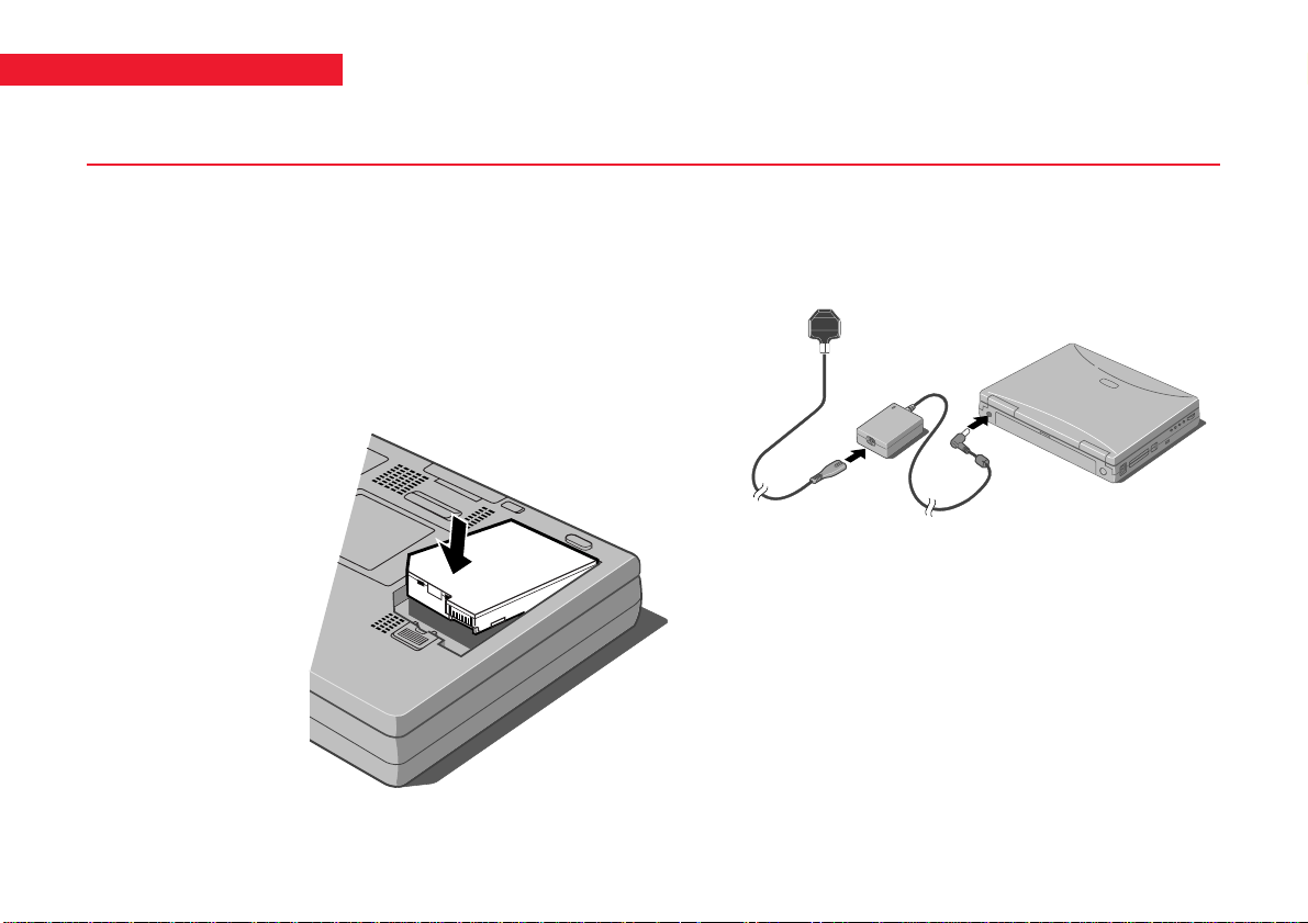
Fitting and charging the battery
Fitting the battery
The battery compartment is located on the underside of
the computer, as shown below. Make sure the system is
switched off and the AC adapter is disconnected before
fitting the battery. To insert the battery, place the end with
the two protruding tabs in the compartment first, then
gently lower the other end until it clicks into place.
Connecting to mains power
Plug one end of the adapter into the mains adapter socket
on the rear of the computer and plug into the mains socket.
Charging the battery
To charge the battery, just switch the computer on using
the AC power adapter. A full charge takes approximately 4
hours. The battery charge indicator LED (located on the
display hinge, just behind the power switch) is yellow when
the battery is charging, and becomes green when the battery
is fully charged. Once the battery is fully charged, it stops
charging automatically. You can use the computer from
mains power while the battery is charging.
2
Page 4
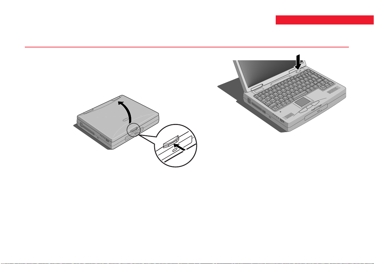
Starting up
Opening the display
Gently push the display release button on the front of the
computer, as shown in the following figure, and lift the
display. Position it at a suitable angle for viewing.
Switching the computer on
Press the Power button, located above the top right hand
side of the keyboard, as shown in the following figure.The
LEDs will light, and the computer will start up.
QUICK START GUIDE
Switching the computer off
To shut down the computer safely, click the Start button
in the Windows taskbar, then click Shut Down. Select
Shutdown the computer and click Yes.
1
1
This pocedure applies to Windows 95, and may be different for
Windows 98. If your computer has Windows 98 installed, refer to
your documentation or on-line Help.
3
Page 5
QUICK START GUIDE
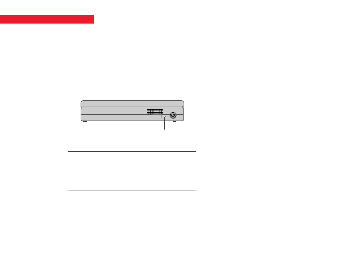
Using the Emergency shutdown button
If the system develops a fault and you cannot access the
Windows Shutdown command, you can quickly shut
down your computer by using the Emergency shutdown
button. This is located on the right side of the computer, as
shown below. This will shut the computer down completely.
Make sure it is an emergency!
In an emergency shut down, you may lose any recent changes
made to the files you are currently working on. The Microsoft
ScanDisk program will run automatically when the computer
next starts, to check for disk errors.
Emergency shutdown
button
4
Page 6

Power saving
Suspend and Standby modes
In order to keep running as long as possible when using
the battery, the computer can be set to enter low power
Suspend and Standby modes when not being used. Full
details of using these modes are explained in Chapter 4,
Battery and Power Management.
Your computer will always meet the Energy Star standard
when it is in Suspend mode.
QUICK START GUIDE
5
Page 7

QUICK START GUIDE
Registering Windows 9x
Your computer has the Microsoft Windows 9x operating
system already in place or pre-installed, so that it is ready for
you to set up when you turn the computer on.
The first time you turn on the computer you must tell
Windows 9x your name (and the name of the company
for which you work, if applicable) and agree to the legal
terms and conditions of the Windows 9x Licence
Agreement.
Windows 9x then spends a few minutes analysing your
computer and configuring itself to take full advantage of
your computer’s components. It also gives you the
opportunity to install a printer. However, you do not have
to install a printer at this time if you don’t want to.
Help files
There are various help files available on the computer. In
particular, you should use the Windows Help, which can
be found in the Start menu, to help with Windows-related
problems. We also recommend that you double-click the
'Important Apricot User Information' icon on your desktop
for late-breaking information relating to your computer.
6
Page 8
APRICOT AL SERIES OWNER’S HANDBOOK
Page 9

Intel, Pentiumand PentiumII are registered trademarks of Intel Corporation.
Microsoft, MS-DOS, Windows
and WindowsNT are registered trademarks of Microsoft Corporation in the US and
other countries.
Other trademarks mentioned within this document and not listed above are the properties of their respective owners.
Information contained in this document is subject to change without notice and does not represent a commitment on the
part of Apricot Computers Limited. Any software described in this manual is furnished under a license agreement. The
software may be used or copied only in accordance with the terms of this agreement. It is against the law to copy any disk
supplied for any purpose other than the purchaser’s personal use.
No part of this manual may be reproduced or transmitted in any form or by any means electronic or mechanical including
photocopying and recording, for any purpose, without the express written permission of the publishers.
Copyright © Apricot Computers Limited 1998. All rights reserved.
Published by:
Apricot Computers Limited
3500 Parkside
Birmingham Business Park
Birmingham, England
B37 7YS
http://www.mitsubishi-computers.com
Printed in the United Kingdom
Page 10

General
OWNER’S HANDBOOK
SAFETY AND REGULATORY NOTICES
Electrical
The system uses a safety ground and must be
earthed.
The AC adapter and the AC power cord is a
‘disconnect device’. Ensure that the AC adapter is
positioned close to the AC power outlet and that the
plug is easily accessible.
The power cord packed with the computer complies
with the safety standards applicable in the country in
which it is first sold. Use only this power cord. Do
not substitute a power cord from any other
equipment.
To prevent fire and electric shock, do not expose any
part of the computer to rain or moisture. Turn off the
computer and unplug all power cords before moving or
cleaning the system unit.
Laser products
Any CD-ROM drive fitted in this system is classified
as a CLASS 1 LASER PRODUCT according to
IEC825 Radiation Safety of Laser Products (Equipment
Classification: Requirements and User's Guide). The
CLASS 1 LASER PRODUCT label is located on the
underside of the system unit.
CLASS 1 LASER PRODUCT
LASER KLASSE 1 PRODUKT
The CD-ROM drive contains a laser system which is
harmful to the eyes if exposed. Do not attempt to
disassemble the CD-ROM drive; if a fault occurs, call
an authorised maintainer.
Safety & regulatory notices 1
Page 11

OWNER’S HANDBOOK
Use the CD-ROM drive only as described in this
manual. Failure to do so may result in exposure to
hazardous radiation.
Ergonomic
When positioning the system unit, take into account
any local or national regulations relating to ergonomic
requirements.
Anti-static precautions
WARNING
Static electricity can cause permanent damage to
electronic components. You should be aware of this risk,
and take precautions against the discharge of static
electricity into the computer.
The computer is at risk from static discharge while the
bottom panels are off. This is because the electronic
components are exposed. Memory modules,
expansion cards and replacement processors are
examples of electrostatic sensitive devices (ESSDs).
All work that involves removing the panels must be
done in an area completely free of static electricity.
We recommend using a Special Handling Area (SHA)
as defined by EN 100015-1: 1992. This means that
working surfaces, floor coverings and chairs must be
connected to a common earth reference point, and
you should wear an earthed wrist strap and anti-static
clothing. It is also a good idea to use an ionizer or
humidifier to remove static from the air.
When installing any upgrade, be sure you understand
what the installation procedure involves before you
start. This will enable you to plan your work, and so
minimise the amount of time that sensitive
components are exposed.
Do not remove the system panels, nor the anti-static
bag or wrapping of any upgrade, until you need to.
Handle static-sensitive items with extreme care.
Keep all conductive material, and food and drink,
away from your work area and the open computer.
2 Safety & regulatory notices
Page 12

OWNER’S HANDBOOK
Maintenance
Switch off and disconnect all cables before attempting
to clean the computer.
Do not use sprays, solvents or abrasives that might
damage the system unit surface. Do not use cleaning
fluids or sprays near air vents, ports, or the diskette
and CD-ROM drives.
Occasionally clean the diskette and CD-ROM drives
using a proprietary head cleaner.
Occasionally wipe the screen with a soft, slightly
damp, lint-free cloth. It is best to use anti-static glass
cleaner on the screen, but do not spray glass cleaner
directly onto the screen; it could run down inside the
case and damage the circuitry.
Transporting
Use common sense when handling the computer;
hard disks in particular can be damaged if the
computer is dropped or handled roughly. As a
precaution, back up the contents of the hard disk to
tape or diskettes before moving the computer.
Switch off and disconnect all cables before attempting
to move the computer. In particular, do not try to
move the computer while it is plugged into the AC
power supply.
If you are planning to use the computer in another
country, it may not be suitable, check with your
supplier, particularly on the availability of the correct
AC power cords and AC adapter.
Note
Any existing maintenance or warranty agreement may
not be supportable in another country. The system may
have to be returned to the supplier.
Safety & regulatory notices 3
Page 13

OWNER’S HANDBOOK
Standards
Safety
This product complies with the European safety
standard EN60950 which will, when applicable,
include the national deviations for the country in
which it is sold.
Electro-magnetic Compatibility (EMC)
This product complies with the following European
EMC standards:
Emissions EN50022 Class B
Immunity EN50082
Notes
All interconnecting cables (for example, signal and
communication cables) should be less than 2 metres
in length. If cable extensions are used, ensure
adequate earth connections are provided and screened
cables are used.
If any metal casework components are removed,
during upgrade work for example, ensure that all
metal parts are correctly re-assembled and all internal
and external screws are re-fitted and correctly
tightened.
Lithium ion battery pack
Using an incorrect battery can result in explosion; replace
only with Mitsubishi Electric Type XB62674 battery.
Return the used battery to your Mitsubishi dealer for
proper disposal. Do not dismantle, burn or expose battery
to temperatures above 100°C/212°F. Remove used
battery from system unit immediately. Keep spare and
used batteries out of the reach of children.
Memory expansion
Turn off power and remove all cables from system and
peripherals before removing memory expansion bay cover.
After installing memory, replace the bay cover before
switching machine on again.
4 Safety & regulatory notices
Page 14

OWNER’S HANDBOOK
E
N
L
125V
250V
N
L
E
250V
Legalities
This equipment complies with the relevant clauses of
the following European Directives (and all subsequent
amendments):
Low Voltage Directive 73/23/EEC
EMC Directive 89/336/EEC
CE Marking Directive 93/68/EEC
Power Connection
Typical AC plugs
250V
E
LN
BS1363A SHUCO NEMA 5-15P SRAF 1962/DB16/87 ASE 1011
U. K. Austria Belgium Taiwan Denmark Switzerland
Important
This system complies with the CE Marking Directive
and its strict legal requirements. Use only parts tested
and approved by Mitsubishi Electric PC Division.
Failure to do so may result in invalidating both the
compliance and your warranty. All expansion cards,
drives and peripherals must carry the CE mark to ensure
continued compliance.
250V
E
NL
Finland France Thailand
Italy Germany Japan
Sweden Norway USA
Holland Canada
Safety & regulatory notices 5
Page 15

OWNER’S HANDBOOK
Checking the AC power supply
When this product is delivered, it is ready for the
commercial AC power supply generally available in
the country in which it is first sold. It is supplied with
an AC power cord and plug which comply with the
relevant safety standards.
Before using the product in a country other than that in
which it was originally sold, you must check the voltage
and frequency of that country’s AC power supply, and
the type of power cord required there. Check the power
rating labels on the bottom of the computer to ensure
that they are compatible with the AC power supply.
Connecting to the AC power supply
Important
Any peripheral equipment that requires an AC power
cord must be earthed.
Use the following guidance to connect the
components together. It is important that you take
each step in the order indicated.
1. Before connecting any components, ensure that
the AC power supply is switched off or
disconnected, and that the system unit, and any
peripherals are turned off.
2. Where appropriate, connect the computer to the
network.
3. Connect the component power cords: system
unit plus any other peripherals to nearby,
grounded AC power outlets. (Never substitute a
power cord from any other appliance). Then
switch on or connect the AC power supply.
4. Turn on the system unit first then any other
peripherals.
Power Cable Connections - UK ONLY
This product is supplied with an AC power unit that
has a non-removable moulded plug.
Always replace the fuse with one of the same type and
rating which is BSI or ASTA approved to BS1362.
Always refit the fuse cover, never use the plug with the
fuse cover omitted.
6 Safety & regulatory notices
Page 16

CONTENTS
OWNER’S HANDBOOK
1 Welcome
Pictorial guide to the system unit.......................... 1/2
Backing up the pre-installed software.................... 1/7
General advice...................................................... 1/9
2 Using the computer’s controls
Using the trackpad ............................................... 2/1
Using the keyboard............................................... 2/2
Use of the infra-red facility................................... 2/6
3 Diskettes and CDs
Diskette drive....................................................... 3/1
CD-ROM drive ................................................... 3/3
Changing the drive configuration ......................... 3/5
Using the floppy diskette drive
as an external device ............................ 3/6
4 Battery and power management
Battery information ...............................................4/1
Power management...............................................4/5
5 Optional devices
Connecting external keyboard or mouse ................5/1
Connecting a serial device......................................5/2
Connecting an external monitor ............................5/2
Connecting a television .........................................5/3
Universal serial bus................................................5/4
6 Upgrading
Adding memory ....................................................6/1
Fitting a PC card...................................................6/3
Contents i
Page 17

OWNER’S HANDBOOK
7 BIOS setup
What is the BIOS setup utility............................. .7/1
Basic operation of the Setup utility ....................... 7/3
Summary of main options within Setup................ 7/5
8 Troubleshooting
System unit .......................................................... 8/2
Floppy diskette drive (FDD)................................. 8/2
Hard disk drive (HDD)........................................ 8/3
CD-ROM ............................................................ 8/4
Battery.................................................................. 8/4
LCD screen .......................................................... 8/4
Serial interface...................................................... 8/5
PC cards.............................................................. 8/5
Expansion memory............................................... 8/6
External keyboard, 10-key pad, mouse.................. 8/6
Printer.................................................................. 8/6
Trackpad...............................................................8/7
External display.................................................... 8/8
Infrared port..........................................................8/9
Microphones, headphones, audio ........................8/10
USB connection..................................................8/10
Appendix
ii Contents
Page 18

1WELCOME
OWNER’S HANDBOOK
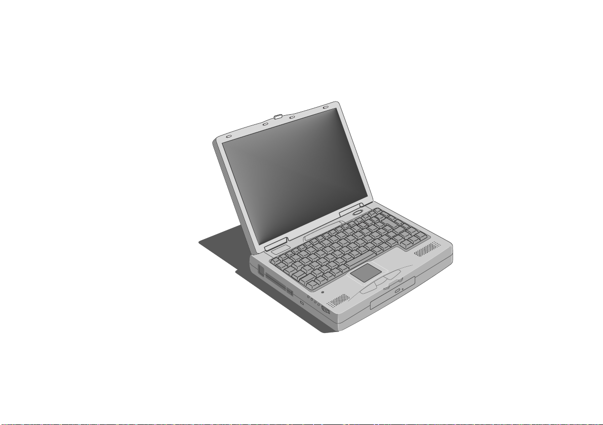
This first chapter gives you a quick tour of your new
Apricot AL Series Notebook PC. It lists the special
features of the computer and has pictorial guides to
help you identify the various parts.
If you want to get started working with your Apricot
notebook computer straight away, follow the
instructions given in the Quick Start Guide at the
front of this manual.
Use the page at the end of this manual to make a note
of the manufacturer’s data recorded on the various
components (product codes, serial numbers, etc.). A
service engineer may need this information if the
computer develops a fault.
For your own safety
Read the Safety & Regulatory Notices section at the start
of this manual before using the computer for the first
time.
Features
Pentium mobile processor
233MHz (AL700)
266/300MHz Pentium II (AL720)
48Mb SDRAM (expandable to 144Mb)
512Kb level 2 cache
2Mb/4Mb
3.5" 1.44Mb FDD (Floppy Disk Drive)
20x/24x
2.5" 3.2Gb/4.0Gb
PC card (PCMCIA) Type II/Type III expansion slot
13.3"/14.2"
1
video RAM
1
(max) CD-ROM drive
1
HDD
1
Thin Film Transistor (TFT)
colour LCD display
Infra-red port (IrDA 1.1 compliant)
Lithium ion battery
1
AL700/AL720
Welcome 1/1
Page 19
OWNER’S HANDBOOK
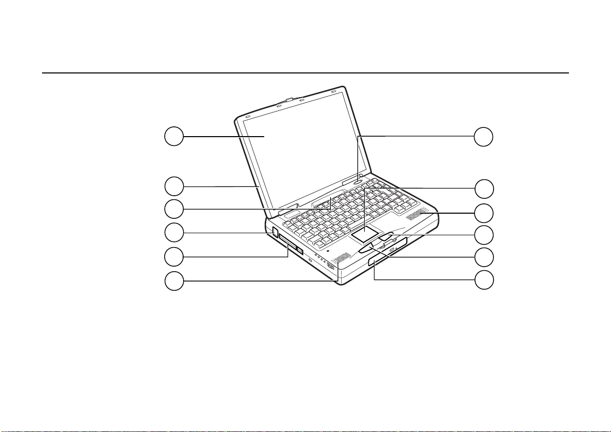
Pictorial guide to the system unit
1/2 Welcome
2
1
11
10
9
5
1. LCD unit
2. TFT display
3. Power switch
4. Trackpad
5. Internal speakers
6. Right button
3
4
5
6
7
8
7. Left button
8. CD-ROM/FDD drive
9. PC card sockets
10. USB port
11. LED indicators
Page 20

Underside of computer
OWNER’S HANDBOOK
6
5
4
1. Hard Disk Drive (HDD)
2. Ventilation grille
3. Lock for CD-ROM/FDD drive bay
1
2
3
4. Internal battery (not fitted initially)
5. Internal battery lock
6. System memory (RAM) compartment
Welcome 1/3
Page 21
OWNER’S HANDBOOK
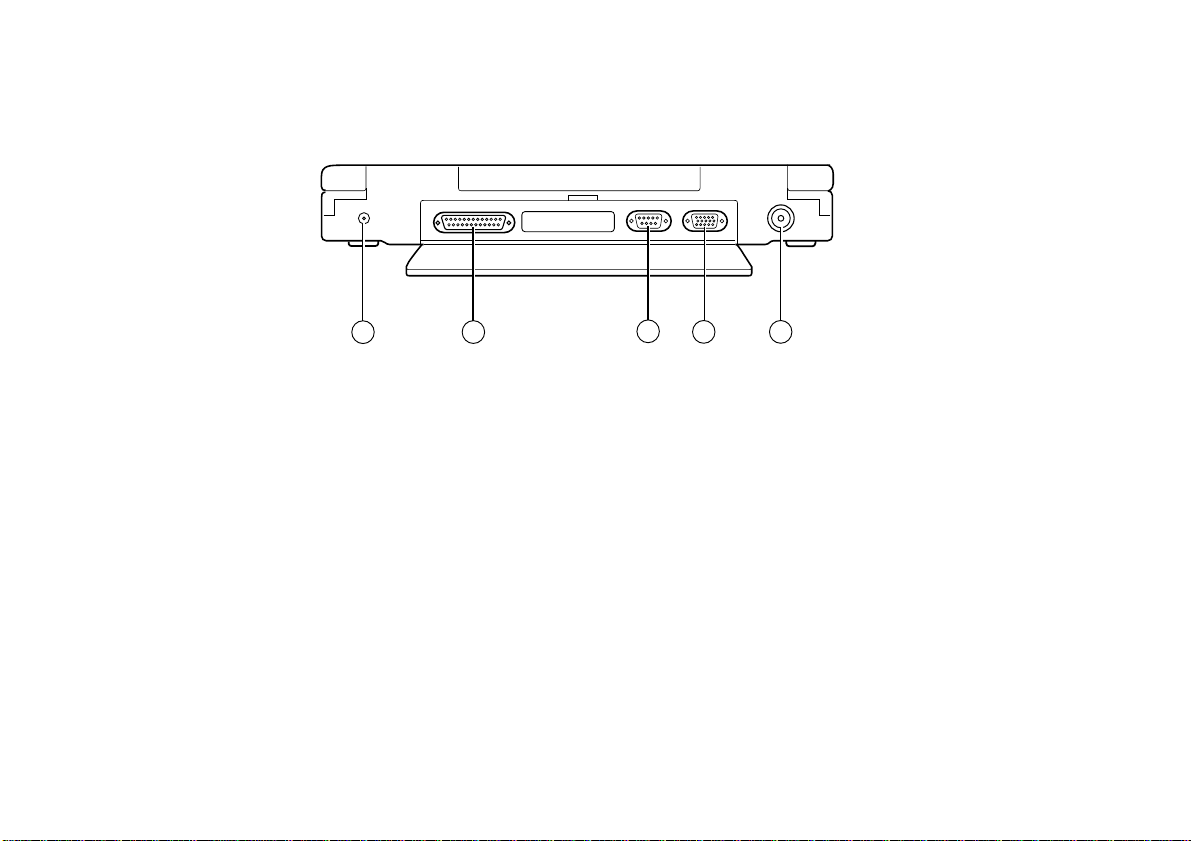
Rear of computer
3
1
2
4
5
1. DC power input
2. Parallel printer port
3. Serial port
1/4 Welcome
4. External monitor connector
5. Television output connector
Page 22
OWNER’S HANDBOOK
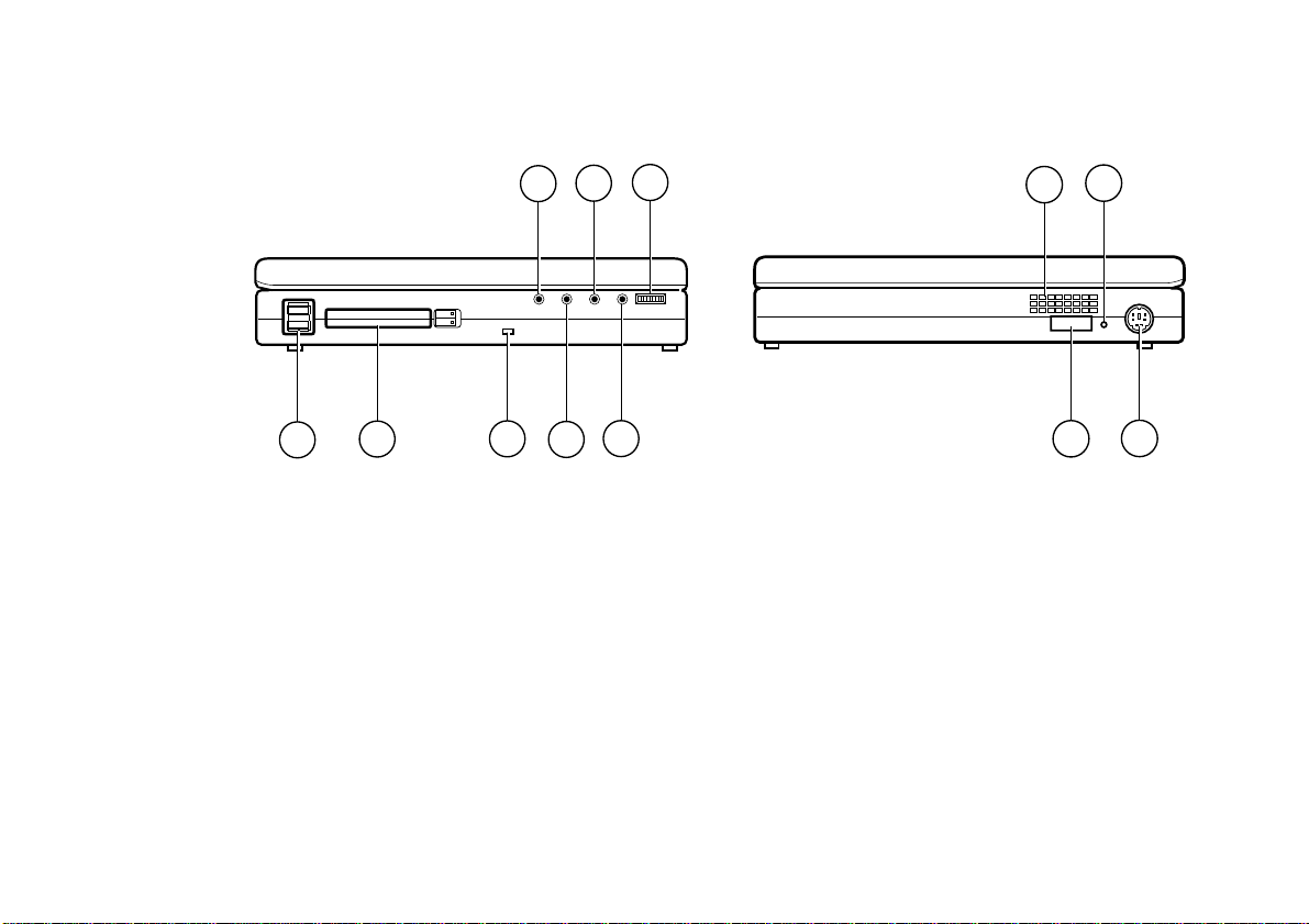
Left side of computer
8
6
4
1
1. USB port
2. PC card socket
3. Security slot - fitting a locking device here will
help to protect computer from theft
4. Microphone input - use this to connect an
external microphone
5. Audio input (line in)
6. Audio output (line out)
7. Headphone socket
8. Volume control
2
3
7
5
Right side of computer
2
1
3
1. Ventilation grille
2. Emergency power off switch - forces the computer
from normal, Standby or Suspend modes into a
full ‘off’ state
3. IrDA port for communication with infrared device
such as a printer
4. External device connection for keyboard or mouse
or keypad
4
Welcome 1/5
Page 23
OWNER’S HANDBOOK
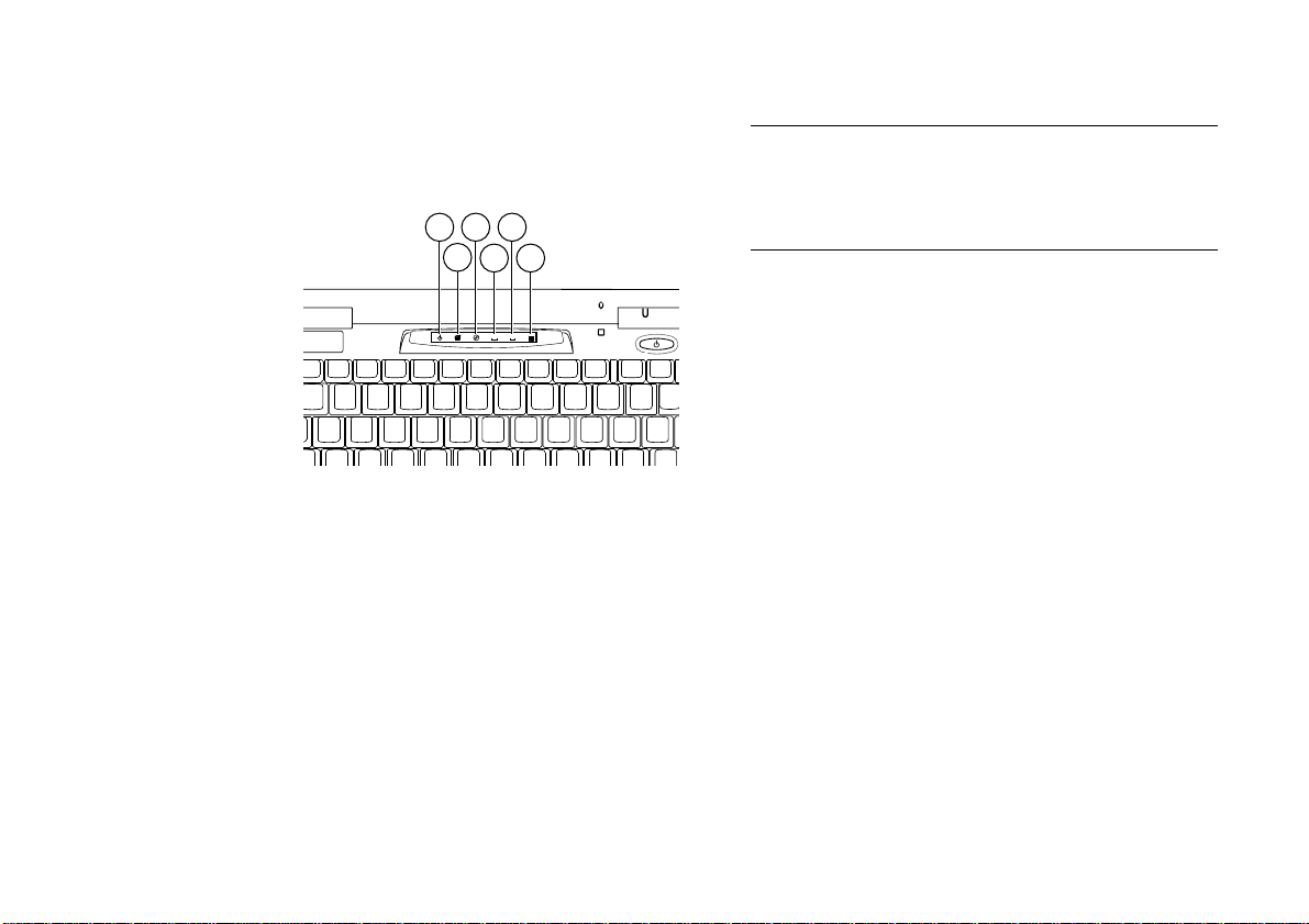
Indicator Panel
3 5
1
2
4 6
A
1
1. Power indicator – this is green when the CPU
speed is slow and orange when it is fast
2. HDD indicator - this is lit when the HDD is
active
3. CD-ROM/FDD indicator - this is lit when
either the CD-ROM drive or the FDD drive is
active
Note
On the AL700, the CD-ROM/FDD indicator is activated
by the drive in the internal bay - it does not work for the
FDD when the FDD is connected as an external device.
4. Caps lock indicator - this is lit when the Caps
Lock key has been pressed
5. Pad lock indicator - this is lit when the numeric
pad is active
6. Scroll lock indicator - this is lit when the scroll
lock is activated
1/6 Welcome
Page 24

Backing up the pre-installed software
OWNER’S HANDBOOK
Apricot PCs arrive with a pre-installed copy of
Windows 9x. Additional software may be preinstalled at the factory or by your Mitsubishi Electric
PC supplier.
We strongly recommend that you copy or ‘back-up’
any pre-installed software soon after setting up the
system. This is particularly important for systems
supplied without installation disks for the software on
the hard disk. A back-up copy will safeguard the preinstalled software against loss if the hard disk fails or if
you accidentally overwrite or delete files.
The Microsoft Create System Disks utility
allows you to create installation diskettes from
disk images pre-installed on the hard disk.
1
1
This procedure applies to Windows 95, and may be
different for Windows 98. If your computer has
Windows 98 installed, refer to your documentation or
on-line Help.
To back up other pre-installed software (and
your own files) use the Backup tool. Click the
Start button in the Windows taskbar, then
Programs, Accessories, System Tools and
Backup.
In general, any copy you make of pre-installed
software must be used only as a back-up copy, in case
the pre-installed version is lost. You are not allowed to
use installation diskettes created from disk images to
install the software onto another computer.
Creating an emergency startup disk
1
We also strongly recommend that you create an
emergency startup disk. This will enable you to start
Windows in the event of your existing Windows
software becoming corrupted.
1. Open the Windows Control Panel by clicking
the Settings option on the Start menu.
2. Double click the Add/Remove programs utility
in the Windows Control Panel.
Welcome 1/7
Page 25

OWNER’S HANDBOOK
3. Click on the Startup disk tab in the
4. Insert a formatted floppy disk into the floppy
5. Click the Create Disk button.
6. Label the floppy disk “Windows 9x
Add/Remove programs Properties dialog.
disk drive.
disk” and keep in a safe place.
2
startup
2
Windows 95 or Windows 98 accordingly
1/8 Welcome
Page 26

General advice
OWNER’S HANDBOOK
As a portable computer, this machine is designed to
be used in various environments. The following
paragraphs contain guidelines in caring for yourself
and your computer.
Place the computer on a firm, level surface if
possible, away from vibration.
Site the computer away from moisture, direct
sunlight, and extremes of heat and cold. Avoid
situations in which the surrounding temperature
or humidity may change rapidly. When the
computer is in use, the temperature should be
between 10 and 35
o
C and humidity between
20% and 80% (with no condensation). Remove
battery if the computer is not being used for
long periods.
Keep the computer unit clean, using a non-
abrasive cloth.
Make sure there is adequate space around the
computer for ventilation.
Ensure that you maintain a healthy posture
when using the computer. Ideally, your feet
should be on the floor and your legs at right
angles, with your upper legs approximately
horizontal. Your back should be kept straight,
and your elbows should be about the same
height as the keyboard. Also, your eyes should
generally be approximately 0.5m from the
display, with the top of the screen as close to
your direct line of vision as possible.
0.5m
Welcome 1/9
Page 27

OWNER’S HANDBOOK
When positioning the system unit, take into
account any local or national regulations relating
to ergonomic requirements. For example, you
should ensure that little or no light is reflected
off the monitor screen as glare, and that the
keyboard is placed in a comfortable position for
typing.
You should be aware that in some places, the use
of a portable computer is strictly forbidden. For
example, you should check before using your
portable computer inside a hospital, or before
boarding an aircraft.
Make sure that any sensitive information on
your computer is protected by using access
passwords.
Keep the computer away from strong magnetic
fields, such as stereo speakers.
Do not use the computer near liquids or
corrosive chemicals
Ensure all cables, particularly power cords, do
not trail across the floor where people walking
past can snag them.
1/10 Welcome
Page 28

2 USING THE COMPUTER’S CONTROLS
Using the trackpad
OWNER’S HANDBOOK
The trackpad is the small square area located in front
of the keyboard. The trackpad, together with the two
buttons in front of it, perform the same function as a
mouse, although if preferred, a conventional mouse
can be used with the computer. Refer to Chapter 5,
Optional devices for details on connecting a mouse.
Throughout this manual, the terminology assumes the
‘conventional’ use of the left and right mouse buttons
i.e. left button to select and drag objects, and right
button to display properties or context. If the function
of these buttons has been changed around by the user,
then this should be borne in mind when reading the
manual.
Navigation
As you move your finger across the trackpad, while
applying gentle downward pressure, the pointer on
the screen will move accordingly. Move the pointer
a large distance by quickly moving your finger across
the trackpad in the required direction several times.
For more accurate positioning of the pointer, much
less movement of your finger is required.
Selecting items on the screen
There are two ways of selecting items on the screen:
Using the buttons
With the pointer over an item, use the buttons
in front of the trackpad in the same way as you
would use the conventional right and left mouse
keys.
Using the trackpad
You can use the trackpad itself as you would use
the select key of a conventional mouse. With the
pointer over an item, tap it once for a ‘singleclick’ and twice for a ‘double-click’.
Using the computer’s controls 2/1
Page 29

OWNER’S HANDBOOK
Moving items around the screen
This is similar to using a conventional mouse. First
use the left button to select an item. If you now keep
the button held down while moving your finger across
the trackpad, the item will be dragged across the
screen.
Using the keyboard
Although the keyboard is similar to a standard
desktop model, some of the keys perform extra
functions in order to conserve space. These extra
functions are shown as blue text, and are shown
shaded in the keyboard illustration on the following
page. Their function is also described in the
accompanying table. To use any of these extra
functions, hold the <Fn> key down while pressing the
required function key.
The numeric keypad overlay
To activate the numeric keypad, press F11 while
holding down the Function key. The Pad lock
LED will light up to indicate that the numeric pad
is activated. Pressing F11 while holding down the
2/2 Using the computer’s controls
Function key again will de-activate the numeric
keypad, returning the keys to their normal functions.
Page 30

OWNER’S HANDBOOK
F7
F6
^
6
TY
HJ
G
BN
V
F9
F8
&
*
8
7
7
8
U
I
456
M
`
Tab
Caps
Lock
F1
!
----
1
Q
Esc Ins
----
Shift
Fn
Ctrl
F3
F2
£
3
2
W
A
S
Z
X
Alt
F5
F4
Standby Suspend
$
4
E
R
DF
C
5
F
11
F
10
)
9
9
O
K
21
<
,
0
Alt Gr
Num Lk
L
F
12
Scr Lk
)
0
P
3
>
.
.
Prt Sc
Pause
BreakSys Rq
-
---
+
{
[
~
#
Shift
Ctrl
BackSpace
Enter
---
=
---
{
[
Enter
.
.
@
.
,
+
`
?
Del
Home
PgUp
PgDn
End
Fn
Using the computer’s controls 2/3
Page 31

OWNER’S HANDBOOK
Key Function
Fn Used in conjunction with the blue function keys
Standby
Suspend
NumLk Activates the numeric keypad
ScrLk Activates the scroll lock feature
Enter Enter
Adjust brightness Adjusts the brightness of the LCD display. (On the AL720, a small
1
For more information on Power Management keys, refer to Chapter 4, Battery and Power Management.
1
1
1
Toggles between the LCD and external CRT displays
Puts the computer into Standby mode
Puts the computer into Suspend mode
icon appears in the top left corner of the screen indicating the
brightness level.)
2/4 Using the computer’s controls
Page 32

OWNER’S HANDBOOK
The Windows key
The Windows
keys have the Windows icon on
them, and they can be found on each side of the
spacebar (two keys along, next to the <Alt> keys).
Pressing either of the Windows keys will display the
Start menu. You can then use the arrow keys instead
of the trackpad or mouse to navigate the menus. To
cancel the menu, press the <Esc> key.
Right-click key
The right-click
key can be used in place of the
right button. In general, it is used (after selecting an
item) to display a menu containing various options
relating to that item. The options shown depend on
the context. To cancel the menu, press the <Esc> key.
Setting keyboard options using the
Windows control panel
1
From the Start menu, click Settings, then click
Control Panel from the submenu which appears. To
view the keyboard properties dialog, double-click the
keyboard icon which is located within the Control
Panel. The keyboard properties dialog contains three
tabs: the Speed tab allows you to control the character
repeat settings; the Language tab allows you to change
the default language which is utilised on the keyboard,
and the General tab allows you to change the default
keyboard type.
1
This procedure applies to Windows 95, and may be
different for Windows 98. If your computer has
Windows 98 installed, refer to your documentation or
on-line Help.
Using the computer’s controls 2/5
Page 33

OWNER’S HANDBOOK
Use of the infrared facility
Your computer is fitted with an IrDA 1.1 compliant
infrared port which enables you to make wireless
communications with infrared devices such as IR
printers. The infrared port is shown in the following
diagram.
IR Port
When using the infrared port, it is important to
ensure that the two devices are aligned in such a way
that the infrared signal is transmitted properly.
Generally, the two ports should be approximately
facing each other, and situated within two metres of
each other. There should also be a clear path between
the two ports. The principle of operation is the same
as that of remote controls for television sets and other
domestic devices.
An Infrared Monitor utility has been pre-installed on
your computer. It allows you to control many aspects of
infrared communication. To access the Infrared
Monitor, click Settings from the Start menu, then click
Control Panel from the sub-menu which then appears.
The utility can then be accessed by double-clicking on
the Infrared icon in the Control Panel. For
convenience, you can also display the infrared icon in
the taskbar by checking the ‘Display the infrared icon
in the taskbar’ option on the Preferences tab.
Changing IR port setting
Although the Infrared Monitor options have been
configured on your computer before leaving the factory, it
will be necessary to re-configure the IR port setting. To
do this, click on the Options tab and select ‘COM2’ in
the ‘Enable infrared communication on…’ menu
The process of setting up infrared communication
with Infrared Monitor is fairly simple, and full details
are provided in Windows 9x Help and in the
Important Apricot User Information on your desktop.
There are however one or two things to bear in mind.
2/6 Using the computer’s controls
Page 34

Generally, the infrared port continuously searches for
IR devices within range, and when one is found, it is
ready for use. Depending on the device however, you
may need to install appropriate driver software before
the device can be used. Refer to the documentation
supplied with your IR device.
The options available in the Infrared Monitor utility
have been correctly configured on your computer
before leaving the factory. Should you have any
problems however, check the settings in the Infrared
Monitor utility. Also, refer to Chapter 8,
Troubleshooting.
OWNER’S HANDBOOK
Using the computer’s controls 2/7
Page 35

Page 36

3 DISKETTES AND CDS
OWNER’S HANDBOOK
Your Apricot Notebook PC comes with a 1.44Mb
floppy diskette drive (FDD) and a 20x/24x
CD-ROM drive. Either one of these drives can be
fitted inside the system unit at any one time. It is also
possible to use the FDD externally using a parallel
cable, while the CD-ROM drive is fitted inside the
Floppy diskette drive (FDD)
Inserting a diskette
1. Insert the diskette with the metal shutter
foremost, and with the label side facing
upwards.
2. Push the diskette all the way in until it ‘clicks’
into place. The drive’s eject button pops out
slightly. The drive flap stays open, leaving the
diskette just visible.
1
AL700/AL720
1
(max.)
system unit. These topics are covered in more detail
later in the chapter.
The bay for the FDD/CD-ROM is in the front of the
computer, as shown in the Pictorial guide in Chapter 1.
Ejecting a diskette
Wait until the drive’s activity indicator is unlit,
then press the
EJECT
button.
If a diskette becomes stuck in the drive, perhaps
because its label has peeled back, do not attempt to
remove it with tweezers or any similar implement; you
risk damaging the drive. Call an authorised
maintainer.
Diskettes and CDs 3/1
Page 37

OWNER’S HANDBOOK
Care of diskettes
Each diskette has a rigid plastic cover, with a metal
shutter that guards the disk surface. Never touch the
exposed surface under the shutter – you could deform
the disk or leave a fingerprint that might make the
diskette difficult to read.
Keep diskettes away from dust, moisture, magnetic
objects, and equipment that generates magnetic fields.
Also, avoid extremes of temperature and exposure to
direct sunlight. Otherwise, data recorded on the
diskette may become corrupted.
Write-protecting a diskette
You can read, copy or print the files on a writeprotected diskette, but you cannot create, rename or
delete any files.
A diskette can be write-protected by sliding a tab
towards the edge of the diskette to expose the
small hole beneath it. Note that the location of
the tab depends on the type of diskette.
3/2 Diskettes and CDs
Page 38

CD-ROM drive
OWNER’S HANDBOOK
The CD-ROM drive can retrieve multimedia data
from CD-ROM discs and multi-session Photo-CD
discs. It can also play normal music CDs.
Keep CDs well away from dust and moisture, and
avoid touching the surface of the CD. Avoid extremes
of temperature and exposure to direct sunlight as
these may cause the disc to warp.
Do not attempt to move the computer while a CD is
in the drive, especially if the CD is being played at the
time.
Warning
The laser beam inside the CD-ROM is harmful to the
eyes if looked at directly. Do not attempt to disassemble
the CD-ROM drive. If a fault occurs, call an authorised
maintainer.
Inserting a CD
1. Press the eject button on the front of drive. The
tray should open partially.
2. Gently pull the drawer fully open in order to
insert the CD.
3. Place the CD centrally, printed side up, on the
platter.
4. While supporting the underside of the CD tray,
gently push the CD down until it snaps onto the
central mechanism.
Diskettes and CDs 3/3
Page 39

OWNER’S HANDBOOK
5. Gently push the platter all the way in until it
Ejecting a CD
1. Ensure that the drive’s activity indicator is unlit,
2. Gently pull the drawer fully open in order to
clicks into place.
then press the
drawer.
remove the CD.
button to partially open the
EJECT
Emergency removal of a CD
To eject the platter manually (for example, during a
power failure) use the emergency eject hole, located
just to the right of the
EJECT
button.
1. Shut down the computer, and turn it off.
2. Insert a thin non-metallic rod into the
emergency eject hole. Push carefully and firmly
to open the drawer.
3/4 Diskettes and CDs
Page 40

Changing the drive configuration
OWNER’S HANDBOOK
It is possible to interchange the FDD with the CDROM drive. Whether you are replacing the CDROM drive with the FDD, or the FDD with the CDROM drive the procedure is similar:
1. Remove any disks from the drive.
2. Shut down the computer, and turn it off.
3. Turn the computer upside down, with the front
facing toward you.
4. Slide the drive securing button to the left while
gently pulling the drive outwards. The drive
should disengage from its connections. Slide the
drive out of its compartment.
5. Put the removed drive in a safe place.
6. Insert the other drive into the vacant
compartment, ensuring it is the correct way up.
The drives only fit one way, so if the drive only
moves so far, you are inserting it the wrong way
round. Push the drive all the way back until it
clicks into place.
Diskettes and CDs 3/5
Page 41

OWNER’S HANDBOOK
Using the floppy diskette drive as an external device
If you need to use a CD-ROM drive and the FDD at
the same time, it is possible to use the FDD as an
external device.
Note
On the AL700, the floppy drive indicator LED only works
when the FDD is being used in the drive bay - it does not
work if the FDD is being used as an external device.
1. Shut down the computer, and turn it off.
2. Connect the parallel cable to the parallel port.
3. Connect the other end of the cable to the FDD.
4. Insert the CD-ROM drive into the internal
drive bay.
5. Switch the computer back on. The computer
will automatically recognise the newlyconnected drive.
6. When disconnecting the FDD, make sure you
remove the parallel cable from the back of the
computer, otherwise the computer will not work
properly.
Caution
When using the FDD externally, ensure that you set
it on a flat surface, and that nothing is placed on top
of the drive.
Keep a firm hold of the drive when inserting or
removing a diskette.
Keep the FDD and the CD-ROM drive in the bag
provided when they are not fitted or connected to the
computer.
When using the FDD as an external device, make
sure that the CD-ROM drive is properly fitted in the
internal drive bay - do not leave this bay empty.
Make sure you shut the computer down before
disconnecting the drive.
Your computer will not work properly if the CD-
ROM drive is connected externally.
3/6 Diskettes and CDs
Page 42

OWNER’S HANDBOOK
4 BATTERY AND POWER MANAGEMENT
Battery information
The computer comes with a rechargeable lithium-ion
battery pack, which provides up to 2.5 hours usage for
the AL700, or 1.7 hours usage for the AL720. The
battery pack can be recharged between 300 and 500
times. After this it will last for a noticeably shorter
time between charges. At this point the battery should
be discarded and replaced.
Caution
It is possible that the battery may not be fully charged
after transit, and we therefore recommend that you
charge the battery before using it. For details on charging
the battery, refer to the section later in this chapter.
Used batteries can be hazardous; see the Safety chapter
for information about battery safety and disposal.
Fitting the battery
The battery is housed in a compartment on the
underside of the computer. To fit the battery, refer to
the Quick Start Guide at the beginning of this
manual.
Removing the battery
Make sure the system is switched off and the AC
adapter is disconnected before removing the battery.
To remove the battery, slide the battery lock towards
the back of the computer, then raise one end of the
battery until the unit can be lifted from the
compartment, as shown in the diagram overleaf.
Battery and Power Management 4/1
Page 43

OWNER’S HANDBOOK
Charging the battery
The battery begins charging whenever you plug the
computer into the mains using the AC adapter. You
can use the computer while the battery is charging.
When the battery reaches full charge, it stops charging
automatically. A full charge takes 3 - 4 hours. You can
monitor the progress of the charge by accessing the
Windows battery meter utility. To view the battery
meter, double-click on the ‘plug’ icon on the taskbar
(beside the clock). Alternatively, you can just hold the
pointer over the icon, and the charge progress will be
displayed.
1
This is in addition to the battery charge
LED, located just above the power switch, which
changes from yellow to green when the battery is fully
charged.
Note
When using the battery, we recommend that you allow it
to charge and discharge completely each time. Partial
charges/discharges will result in a drastic reduction of the
battery’s lifetime.
1
This procedure applies to Windows 95, and may be
different for Windows 98. If your computer has
Windows 98 installed, refer to your documentation or
on-line Help.
4/2 Battery and Power Management
Page 44

OWNER’S HANDBOOK
How to use the battery efficiently
There are a number of factors which affect the
lifetime of the battery. These include:
Use of Power Management. Refer to the Power
Management section later in this chapter for
further details.
The type of work you do with your computer.
For example, excessive saving of large files to disk
tends to draw a relatively large amount of power.
System configuration.
There are many aspects of system configuration
which have direct affect on the lifetime of the
battery. For example, disabling the sound or the
serial and parallel ports can help to conserve
battery power.
If the battery is not going to be used for a long period
of time, it should be run down to a low charge,
removed from the computer, and stored in a place
which is not subject to high levels of humidity, within
the temperature range 0-40C.
Ensure a good connection to the battery is maintained
by keeping both terminals of the battery clean and dry.
If the parallel or serial port are not being used, disable
them in Setup, as this will conserve some power.
Refer to Chapter 7, BIOS setup for further details.
The system should be used within the temperature
range 10-35C at all times.
If the battery is running out
Whenever using the computer with the battery pack,
you should check the battery-level frequently. You can
do this by checking the Windows battery meter, as
described in the previous section.
You can also have visible and audible warnings which
come into operation when the battery is low on
charge. The visible warnings come into operation
automatically, but the audible warnings can be
enabled and disabled in Setup. For details on setting
this function, refer to the Power Management section
later in this chapter and the Setup utility.
These low-power warnings are comprised of two
distinct stages, as described in the following table.
Battery and Power Management 4/3
Page 45

OWNER’S HANDBOOK
Power level of battery Visible warning Audible warning
Stage 1 (small amount of power left) Power LED flashes every
second
Stage 2 (almost no power left) Power LED flashes every 0.5
second
Depending on how the computer is being used, Stage
2 continues for up to 5 minutes, at which point the
computer enters Suspend mode. Depending on how
Suspend mode has been configured in Setup, memory
contents are either saved to the HDD, or retained in
RAM. For further information on configuring
Suspend mode, refer to the Power Management
section overleaf.
A single beep
A single beep every minute
until power runs out.
4/4 Battery and Power Management
Page 46

Power Management
OWNER’S HANDBOOK
In order to maximise battery life, this computer makes
use of an advanced Power Management feature. It is
recommended that you make use of the Power
Management facilities when you are using battery
power.
In general, Power Management allows the computer
to revert to a low power mode when it is not being
used. There are two basic levels of low power mode:
Suspend and Standby.
Suspend mode is the highest level Power Management
mode, offering the lowest power consumption. It can
also be configured to operate in two different ways, as
described later in this section. Standby mode is an
intermediate level of Power Management which uses
slightly more power than Suspend mode. It turns off
various devices in the system, including the screen,
until you start using the computer again.
There are many ways of configuring the various
Power Management features, both for AC power and
DC (battery) power.
Turning Power Management on and off
All aspects of the Power Management features are
controlled from the Setup utility. For further
information on navigating the Setup utility, refer to
Chapter 7, BIOS setup, or the Help within the Setup
utility itself.
1. Enter the Setup utility by pressing the F2 button
when prompted during Startup.
2. Select either the AC Mode Power Savings or the
DC Mode Power Savings from the Power menu.
3. To switch Power Management off, set the Power
Savings menu option to ‘Disabled’; to switch it
on, set it to one of the other options, described
below.
You can set ‘Customized’ Savings if you want to
control the other Power Management fields on
this page, or you can set one of the other predefined set of Power Management parameters Maximum Power Savings or Maximum
Performance.
Battery and Power Management 4/5
Page 47

OWNER’S HANDBOOK
Standby mode
There are two ways of entering Standby mode:
Standby timeout
Using the Power Management keys
Standby timeout
Standby mode can be triggered by a period of
inactivity on the keyboard and the mouse. This period
of inactivity is called the Standby timeout, and it can
be as short as 1 minute. There are default Standby
timeouts for the pre-defined Power Saving
parameters, as mentioned in the previous section, or
you can set the Standby timeout manually as follows:
1. Switch Power Management to ‘Customized’, as
described in the previous section.
2. Change the Standby timeout setting to the
desired value.
Your computer will now enter Standby mode after the
specified period of inactivity. To exit from Standby
mode, press any key, or move your finger along the
trackpad.
Power Management keys
1. To enter Standby mode, press the <Fn>
<F4> keys.
2. To exit from Standby mode, press any key, or
move your finger along the trackpad.
Suspend mode
As previously mentioned, Suspend mode can be
configured to operate in two different ways:
Save to Disk mode
In Save to Disk mode, the contents of the RAM
are saved to the HDD before the computer
switches off. This mode uses less power than
Memory Suspend mode.
Memory Suspend mode
In Memory Suspend mode, the contents of
RAM are preserved when the computer enters
Suspend mode. This mode uses slightly more
power than Save to Disk mode.
You can configure the operation of Suspend mode by
changing the Suspend Mode option in the Power
menu in Setup.
4/6 Battery and Power Management
Page 48

OWNER’S HANDBOOK
There are four ways of entering Suspend mode:
Using the Power switch
Using the Power Management keys
Using Auto Suspend timeout
Closing the display lid
The Power switch
To enter Suspend mode using the Power switch, you
need to configure the Power switch to operate as a
Suspend/Resume switch in Setup.
1. Enter the Setup utility by pressing the F2 button
when prompted during Startup.
2. Select Power Switch from the Power menu, and
set it to ‘Suspend/Resume’.
3. Exit from the Setup utility using the ‘Exit Saving
Changes’ option.
4. Use the Power switch to enter and exit Suspend
mode.
Switching computer off
When using the Power switch in this way, hold the
Power switch down for four seconds to switch the
computer off.
Power Management keys
1. To enter Suspend mode, press the <Fn>
<F5> keys.
2. To exit from Suspend mode, press the Power
switch.
Auto Suspend timeout
You can set your computer to enter Suspend mode
automatically after a given amount of time in Standby
mode. This period spent in Standby mode is called
the Auto Suspend timeout. This can be set to a
desired value:
1. Enter the Setup utility by pressing the F2 button
when prompted during Startup.
2. Select either the AC Mode Power Savings or the
DC Mode Power Savings from the Power menu.
Battery and Power Management 4/7
Page 49

OWNER’S HANDBOOK
3. Set the Power Savings option to ‘Customized’
4. Set the Auto Suspend timeout to the desired
value.
5. Exit from the Setup utility using the ‘Exit Saving
Changes’ option.
Note
For the Auto Suspend timeout option to operate, you
need to enter a value in the Standby timeout option.
Using the display lid switch
You can set your computer to enter Suspend mode
when you close the display lid.
1. Enter the Setup utility by pressing the F2 button
when prompted during Startup.
2. Select Lid Switch from the Power menu, and set
it to ‘Suspend’.
3. Exit from the Setup utility using the ‘Exit Saving
Changes’ option.
The computer will now enter Suspend mode when
you close the display lid. Press the Power switch to
resume normal operation.
Suspend mode on a network
If using your computer on a network, do not use Suspend
mode, otherwise your computer may not remain visible to
other computers on the network.
Windows NT users
The Suspend function should not be used with any
version of Windows NT.
Enabling audible ‘low battery’ warning
As mentioned in the battery section, your computer
gives you an audible warning when the battery is low
on charge. This can be enabled in Setup as follows:
1. Enter the Setup utility by pressing the F2 button
when prompted during Startup.
2. Select Low Battery Beep from the Power menu,
and set it to ‘Enabled’.
3. Exit from the Setup utility using the ‘Exit Saving
Changes’ option.
4/8 Battery and Power Management
Page 50

5 OPTIONAL DEVICES
It is possible to connect various optional devices to the
computer. This chapter provides advice on the types
of devices that can be connected, and how to connect
them.
Switching computer off
For most of the procedures in this chapter, we
recommend turning the computer off first. Suspend and
Standby modes are not the same as ‘off’; make sure the
machine is properly switched off.
When using the Power switch in Suspend/Resume mode,
you can switch the computer off by holding the Power
switch down for four seconds.
Connecting external keyboard or mouse
1. Shut down the computer, and turn it off.
2. Connect the device to the socket on the right
side of the computer, as shown below.
OWNER’S HANDBOOK
3. Turn the computer back on.
4. To disconnect the device, turn the computer off
and unplug the cable.
Note
Since you can only use one mouse at a time, the trackpad
will automatically be disabled if you connect an external
mouse.
Optional devices 5/1
Page 51

OWNER’S HANDBOOK
Connecting a serial device
You can connect a serial device using the computer’s
RS-232-C port, located on the back of the computer,
as shown in the following diagram.
1. Shut down the computer, and turn it off.
2. Connect the device to the serial port on the back
of the computer.
3. Make sure the serial port is configured correctly
in Setup. Serial port configuration is part of the
I/O device configuration in the Advanced menu.
4. Switch the computer back on.
Connecting an external monitor
You can connect an external monitor to your
computer. It is possible to view both the computer
display and an external monitor together, although
you can only edit one of the screens at any one time.
1. Shut down the computer, and turn it off.
2. Make sure the monitor is switched off. Connect
the monitor to the monitor port on the back of
the computer.
3. Switch the computer and the device back on.
4. From the Start menu, select Settings, then
Control Panel. Double-click the Display icon to
show Display Properties, and click on the
5/2 Optional devices
Page 52

OWNER’S HANDBOOK
CHIPS tab. In the options, click the ‘Both’
button to enable operation of two monitors.
1
5. Click OK to exit Display Properties.
6. Close the Control Panel (File menu).
7. To toggle between the LCD display and the
external monitor, use the <Fn> <F3> keys.
To disconnect the external monitor, switch the monitor
off, then shut down the computer, and turn it off.
Note
Make sure that the resolution of the monitor is set to that
of the computer’s LCD display before connecting it,
otherwise the display may not appear correctly.
1
This procedure applies to Windows 95, and may be
different for Windows 98. If your computer has
Windows 98 installed, refer to your documentation or
on-line Help.
Connecting a television
You can connect a television to your computer. It is
possible to view the display and the television together.
1. Enter the Setup utility by pressing the F2 button
when prompted during Startup.
2. Set the TV Out option in the Main menu to the
correct international standard (NTSC or PAL).
3. Shut down the computer, and turn it off.
4. Make sure the television is switched off.
Connect the computer to the composite video
input on the television using on the back of the
computer, as shown in the following diagram.
Composite Video
5. Switch the computer and the television on.
6. To toggle between the LCD display and the
television, use the <Fn> <F3> keys.
Optional devices 5/3
Page 53

OWNER’S HANDBOOK
To disconnect the television, switch the television off,
then shut down the computer, and turn it off.
Universal Serial Bus
The USB is a new way of connecting peripherals, such
as monitors, scanners and other input devices to your
computer. It has several advantages over serial and
parallel ports. The main advantage is that a USB
peripheral is automatically configured once it is
physically connected, eliminating the need to reboot
or run a setup program. Several USB devices can be
“daisy-chained” together so that a single connector on
your computer can support a range of devices at once.
USB devices are also “hot-pluggable”; that is, they can
be connected and disconnected without turning off
the computer. The USB can supply DC power to
certain devices, so that they do not need an
independent power supply. It is also fast, operating at
12 megabits per second, which is appropriate for a
wide range of applications including video
conferencing cameras.
The computer has two USB connectors. The USB
port is located on the left side of the computer, as
shown in the following diagram.
Before connecting any USB device, we recommend
that you read all documentation provided with the
device.
USB Port
5/4 Optional devices
Page 54

6 UPGRADING
Adding memory
OWNER’S HANDBOOK
Your computer is shipped with 48Mb of memory
(SDRAM) as standard. This will ensure that most
applications currently available will run quickly and
efficiently. It is possible however, to add more
memory, up to a maximum of 144Mb.
The memory modules used in this computer are SODIMMs (Small Outline Dual Inline Memory
Modules). There is provision for two SO-DIMMs in
the memory compartment. There is already a 32Mb
SO-DIMM inserted, which, combined with the
16Mb of memory on the motherboard, gives the
standard 48Mb. You can fit any two SO-DIMMS
from the available values (8, 16, 32, 64Mb), giving a
maximum of 144 Mb of RAM. The two SO-DIMMS
do not have to be equal amounts of memory.
When purchasing memory, we recommend that you
contact your Mitsubishi dealer. This will ensure that
you obtain the correct module.
Caution - electrostatic discharge
Memory modules are extremely sensitive to electrostatic
discharge, and can easily be damaged by small amounts
of static electricity present on the body. To avoid causing
damage, it is recommended that you discharge any static
electricity by touching something metal before handling
memory modules.
Also, when handling memory modules, make sure you
hold them by the edges, avoiding contact with the chip or
the contacts.
Upgrading 6/1
Page 55

OWNER’S HANDBOOK
Inserting a SO-DIMM
Caution
Suspend and Standby modes are not the same as ‘off’;
make sure the machine is properly switched off.
When using the Power switch in Suspend/Resume mode
(as described in the ‘Suspend mode’ section of Chapter 4,
Battery and Power Management), you can switch the
computer off by holding the Power switch down for four
seconds.
1. Shut down the computer, and turn it off.
2. Close the lid of the computer.
3. Remove the battery and the AC adapter.
4. Remove the screw securing the memory
compartment lid, and lift the lid off. The
memory compartment is located on the
underside of the computer, as shown in the
following diagram.
6/2 Upgrading
5. Carefully slot the memory module into the vacant
slot in the memory compartment. Push the
module firmly into place to insert properly.
6. Replace the memory compartment cover.
7. Switch the machine back on. The computer
detects the new memory automatically.
8. Check that the memory has been detected by
double-clicking on the System icon in the
Control Panel. The amount of RAM available is
displayed at the bottom of the System Properties
dialogue.
Page 56

Fitting a PC card
PC cards (previously PCMCIA), are a useful way of
adding functionality to your computer.
In general, there are three types of PC card. These all
have the same length and width (85.6mm x 54.0mm),
but each has a different thickness, as described in the
following table:
Type Thickness
I3.3Memory
II 5.0 I/O (Modem, LAN etc.)
III 10.5 Mass storage
This computer supports Types I, II and III, as well as
the Cardbus and Zoomed Video (ZV) standards.
There are two slots in the card socket, allowing two
PC cards to be fitted at once. There are however,
restrictions on which type of card can be fitted in each
slot. The restrictions are detailed in the following
table:
(mm)
Typical usage
OWNER’S HANDBOOK
Slot Cards which can be used
Top Type I, Type II, ZV, Cardbus
Bottom Type I, Type II, Type III, Cardbus
In general, you can use a different card in each slot
simultaneously. This however does not apply if a
Type III card is being used in the bottom slot, in
which case there will be no room for a card in the top
slot.
When using Windows 95, PC cards are ‘hot-pluggable’.
That is, you can change a card while the computer is
switched on, just as you can with floppy diskettes.
1
This
is not the case however with Windows NT. If you are
using Windows NT, refer to the note overleaf.
1
This procedure applies to Windows 95, and may be
different for Windows 98. If your computer has
Windows 98 installed, refer to the documentation
which came with your PC card, and/or your
Windows documentation/on-line Help.
Upgrading 6/3
Page 57

OWNER’S HANDBOOK
PC cards may become fairly hot during normal use.
This is normal, and does not indicate a fault with
either the PC card or your computer.
Note for Windows NT users
Cardbus and ZV cards cannot be used with any version
of Windows NT.
You must shut the computer down completely to change a
PC card when using Windows NT.
Inserting a PC card
If connecting an external device to the PC card, you
should switch the device on and plug it into the PC
card before inserting the PC card into the slot.
1. Slide the PC card into the required slot, making
sure it is aligned correctly. There is usually an
arrow on the PC card to indicate which way to
insert it. Failing this, the edge with the row of
connection holes must go in first. When the
card is fully inserted, the eject button to the
right of the card should pop outwards. To
prevent damage to the button, push it round to
the right into the space provided for it.
2. The card should automatically be recognised by
the computer. Follow the instructions on screen,
or refer to the documentation which came with
your PC card to install the necessary driver
software.
Removing a PC card
1. Gently turn the eject button back round to the
protruding position. Press it in, and the PC card
should pop out slightly.
2. Remove the PC card from the slot.
6/4 Upgrading
Page 58

7 BIOS SETUP
What is the BIOS Setup utility?
OWNER’S HANDBOOK
The BIOS (Basic Input/Output System) mediates
between the computer’s hardware – the processor,
memory, and so on – and its software – the operating
system and your programs. The BIOS program is kept
in permanent, read-only memory or ROM (although
if necessary it can be upgraded by an authorised
maintainer).
BIOS Setup is a helpful utility that forms part of the
BIOS program. It allows you to view and alter the
computer’s hardware configuration. Configuring the
computer is necessary to ensure that the software you
use can recognise and exploit the hardware’s
capabilities.
The current configuration is kept in a special area of
memory, called CMOS (Complementary Metal
Oxide Semiconductor) memory, and maintained by a
battery so that the configuration is preserved even
while the computer is switched off.
Your computer arrives already configured, but may
need to be configured again after you add or remove
add-on options such as memory or expansion cards.
Whenever the computer is turned on, the BIOS
power-on self-test (POST) routine tests various
hardware components, including memory, and
compares the actual configuration of the computer
with that recorded in permanent (CMOS) memory.
The BIOS Setup utility is used for the following tasks:
Setting the Power Management options
Setting security options
Enabling the IrDA port
Enabling the audio functions
Setting options after connecting an external
device
Checking the memory configuration after fitting
additional memory
BIOS Setup 7/1
Page 59

OWNER’S HANDBOOK
Using the Setup utility is fairly straightforward; all of
the options available are constantly displayed at the
bottom of the screen, and there is item-specific help
displayed on the right of the screen for whichever
item is selected. The Setup utility contains the
following main headings:
There are many parameters which can be changed in
the Setup utility. These can easily be reviewed by
browsing through the Setup utility itself, and are
therefore not covered in detail here. There are,
however, several important functions which are
covered in the Summary of main options section later
in the chapter.
Main
Advanced
Security
Power
Boot
Exit
7/2 BIOS Setup
Page 60

Basic operation of the Setup utility
OWNER’S HANDBOOK
Starting BIOS Setup
To start the BIOS Setup utility:
1. Turn on or restart your computer.
2. Wait until the ‘Press F2 key for Setup’ message
appears on the screen.
3. Press the F2 key.
4. If you have previously defined a Supervisor
password, you are prompted for it before BIOS
Setup starts.
If BIOS Setup starts on its own
BIOS Setup might start on its own for three reasons:
The power-on self-test (POST) detects a
configuration error or fault. This may be
signalled by one or more POST error messages.
If a persistent fault is indicated, make a note of
any error messages and the current configuration
settings before calling an authorised maintainer.
The CMOS battery may be running down. This
may cause spurious POST error messages. If this
happens every time you turn on the computer,
you may have to change the battery. Contact
your Mitsubishi dealer to have the CMOS
battery renewed.
The computer’s configuration may have
changed, for example by the addition of more
system memory or an expansion card. In this
case you may have to define the new
configuration.
BIOS Setup 7/3
Page 61

OWNER’S HANDBOOK
Press To
1 or
F
ALT-H
View a general help topic. Press
ESC
to
close the help window.
ESC
or
LEFT
or
UP
DOWN
(+) or F6 or
PLUS
(-) or F5. Select the previous value for the current
MINUS
arrow Select a different menu.
RIGHT
arrow Select fields on the current menu.
SPACEBAR
Exit the current menu.
Select the next value for the current field.
field.
ENTER
Execute a command or enter a submenu.
HOME
or
END
Move the cursor to the top or bottom of
the current menu.
PGUP
or
PGDN
Move the cursor to the next or previous
page of the current menu.
9 Restore the default settings for all menus.
F
10 Save the changes you’ve made and exit
F
from BIOS Setup.
Control keys
Use the keys listed in the legend bar at the bottom of
the BIOS Setup screen to make your selections or exit
the current menu.
Sub-menus are marked by a
sub-menu, use the arrow
the sub-menu you want, then press
pointer. To display a
keys to move the cursor to
.
ENTER
Changeable fields are enclosed in square brackets. To
select an item, use the arrow
to the field you want. Then use the
(–) keys to select a value for that field.
MINUS
keys to move the cursor
(+) and
PLUS
Caution
The default BIOS settings are not necessarily the same as
the original settings when shipped, and therefore may not
be appropriate for your particular system. Make a note of
the current settings before pressing
9 or using the Load
F
Setup Defaults command of the Exit menu.
7/4 BIOS Setup
Page 62

Getting help in BIOS Setup
You can get general help about the control keys at any
time by pressing the F1 key.
The Help window on the right-hand side of each
menu displays help text for the currently-selected
field. It changes as you move the cursor from one field
to another.
Summary of main options within Setup
OWNER’S HANDBOOK
This section covers a selection of Setup options which
are particularly relevant to notebook computers.
Original settings when shipped are listed where
applicable.
Power Management setup
The Power Management can be configured by setting
the options in the Power menu. The main options are
listed below. For further information refer to Chapter
4, Battery and Power Management, and the Setup
utility itself.
Power switch
The power switch can be set to function as an on/off
switch, or as a switch to take the computer in and out
of Suspend mode.
The original setting for this option is: On/Off.
Lid switch
When the display lid is lowered, it activates a switch
which can either take the computer into Suspend mode,
or turn the display backlight off, depending on the setting
of this option.
The original setting for this option is: Backlight off.
BIOS Setup 7/5
Page 63

OWNER’S HANDBOOK
Low battery beep
If this option is enabled, the computer will emit beeps
when the battery is low, as described in ‘If the battery
is running out’ section of Chapter 4, Battery and
Power Management.
DC mode power savings
This option contains a submenu which gives you full
control over the DC Power Management settings.
The original setting for this option is: Disabled.
AC mode power savings
This option contains a submenu which gives you full
control over the AC Power Management settings.
The original setting for this option is: Disabled.
Security function setup
The main Security options are as follows:
Set supervisor password
This option allows you to set a password which can be
used by a supervisor to access the Setup utility. Setting
this password also allows a user password to be set.
Set user password
This option allows you to set a password for a user to
access the system. If this password is set and enabled,
users will be prompted for a password before
Windows starts.
Password on boot
This option allows you to enable or disable the user
password.
IrDA setup
The infra-red facility can be configured in the I/O
Device Configuration menu which is a submenu of
the Advanced menu. You can control how the IR port
is enabled, and the mode of operation of the port. For
further information refer to the documentation which
came with your IR device, and to the Setup utility
itself.
7/6 BIOS Setup
Page 64

8 TROUBLESHOOTING
This chapter offers advice if you suspect a fault with
your computer. It is concerned mainly with
problems caused by the computer itself; problems
more often arise from other sources such as your
operating system or application software.
If you are apprehensive
Make a note of any of the symptoms, error codes,
displayed messages and so on, then turn off the
computer and unplug all power cords before consulting
your supplier or maintenance provider.
If something goes wrong …
Read this chapter.
Review the rest of this manual to make sure
you are operating the computer correctly.
Read the on-line Help.
OWNER’S HANDBOOK
Consult your Mitsubishi Electric PC supplier
or authorised maintainer.
Troubleshooting 8/1
Page 65

OWNER’S HANDBOOK
System Unit
Problem
Cannot switch system on
Possible solutions
Floppy Diskette Drive (FDD)
Problem
Drive does not work
Possible solutions
Diskette cannot be read
If using internal battery, it may need to be charged.
If using AC adapter, check that it is connected properly and switched on.
Check that diskette is properly inserted.
Check that diskette is properly formatted.
Check that the drive is properly inserted, or if being used externally, that
the parallel cable is properly connected.
Check that the FDD controller is Enabled in Setup (Refer to Chapter 7,
BIOS Setup and the Setup utility itself).
If the system has recently been subject to an unusually high or low
temperature, allow at least one hour for the system to reach the new
ambient temperature.
If the system has recently been moved from a high temperature to a
lower temperature, there may be condensation present. Allow at least an
hour for it to evaporate.
8/2 Troubleshooting
Page 66

Hard Disk Drive (HDD)
OWNER’S HANDBOOK
Problem
System does not boot from
disk
Possible solutions
Check that the Setup settings are correct. (Refer to Chapter 7, BIOS
Setup and the Setup utility itself).
Certain Windows system files may have become corrupted. Use the
Emergency Windows start-up diskette which you created during the
‘Backing up the pre-installed software’ process in Chapter 1, Welcome.
Make sure that the floppy drive does not have a diskette in it.
Windows does not start
correctly
HDD contents cannot be
read
Start-up in Windows Safe Mode by pressing <F8> at the “Starting
Windows 9x” prompt.
If the system has recently been subject to an unusually high or low
1
temperature, allow at least one hour for the system to reach the new
ambient temperature.
If the system has recently been moved from a high temperature to a
lower temperature, there may be condensation present. Allow at least an
hour for it to evaporate.
1
This procedure applies to Windows 95, and may be different for Windows 98. If your computer has Windows
98 installed, refer to your documentation or on-line Help.
Troubleshooting 8/3
Page 67

OWNER’S HANDBOOK
CD-ROM
Problem
Drive does not work
Contents of CD cannot be
read
Battery
Problem
Battery will not fully charge,
or battery life is very short
LCD screen
Problem
Screen appears blank
Possible solutions
Check that the drive is properly fitted in the bay.
Check that the CD is inserted correctly.
Check that the CD is free from fingerprints and dust.
Possible solutions
Make sure you are charging the battery correctly. Refer to Chapter 4,
Battery and Power Management.
Replace the battery. The battery is a consumable item, and will become
less efficient after it has been charged between 300 and 500 times.
Possible solutions
Check whether the Power Management facility is operating, as
described in Chapter 4, Battery and Power Management.
8/4 Troubleshooting
Page 68

Serial interface
OWNER’S HANDBOOK
Problem
Serial device does not work
PC cards
Problem
PC card does not work
Possible solutions
Check the cable connection.
Check that the Setup settings are correct. Refer to Chapter 7, BIOS
Setup and the Setup utility itself.
Check that required device drivers are installed.
Possible solutions
Check that the card is fitted properly. Refer to Chapter 6, Upgrading.
If the PC card requires an external cable e.g. for connection to
telephone line, check that this is connected correctly. Refer to the
documentation which came with the PC card.
Check that the PC card device driver software is properly installed.
Again, refer to the relevant documentation.
In general, Suspend mode should not be used with Type II
(communications) PC cards, as it affects the remote connection. If
Suspend mode has been activated, this may cause a PC card to operate
incorrectly. Restart the computer.
Troubleshooting 8/5
Page 69

OWNER’S HANDBOOK
Expansion memory
Problem
System operates incorrectly
after fitting expansion
memory
Possible solutions
Check that you have installed a SO-DIMM which is recommended by
Mitsubishi. For details contact your Mitsubishi dealer.
Check that the SO-DIMM has been correctly inserted, as outlined in
Chapter 6, Upgrading.
External keyboard, 10-key pad, mouse
Problem
External device does not work
Possible solutions
Check that the device has been connected properly. Refer to Chapter 5,
Optional devices.
If using a mouse, remove the ball from inside the mouse, and clean it.
Printer
Problem
Printer does not print
Possible solutions
Check the printer cables and connections.
Make sure the printer port is configured correctly in Setup. Port
configuration is part of I/O Device Configuration in the Advanced menu.
Check that the printer driver software is properly installed. Check with the
documentation which came with your printer for further information.
8/6 Troubleshooting
Page 70

Trackpad
OWNER’S HANDBOOK
Problem
Trackpad does not work at all
Trackpad responds slowly
Possible solutions
Make sure the PS/2 mouse is “Enabled” in the Advanced menu in
Setup.
If a PS/2 mouse is connected as an external device, the trackpad is
automatically disabled. You cannot use two pointing devices
simultaneously.
Make sure there is nothing metallic on or near the trackpad.
Make sure both the trackpad and your finger are clean and dry.
Troubleshooting 8/7
Page 71

OWNER’S HANDBOOK
External display
Problem
Nothing appears on the
external display
Cannot switch from the LCD
screen to the external display
Cannot obtain high
resolution (> 800x600 pixels)
on either screen
The display is shifted or
distorted
Possible solutions
Check that the display is powered up.
Make sure the brightness and contrast controls are adjusted properly.
Press <Fn> <F3> to change between the LCD screen and the
external display.
Check that the display resolution and refresh rate settings are the same
for each screen. These can be set in the Display Properties dialog in the
Windows Control Panel.
Check that the external display supports the resolution which the LCD
is currently using.
Make sure that a high resolution (i.e. 1024x768 pixel) driver has been
installed.
Make sure the resolution capability of the external monitor is equal to
(or better than) that of the LCD display. Refer to Chapter 5, Optional
devices for further information.
8/8 Troubleshooting
Page 72

Infra-red port
OWNER’S HANDBOOK
Problem
The infra-red feature does not
work
Erroneous data is transmitted
and/or received
Possible solutions
Make sure the IR Monitor in the Windows Control Panel is configured
correctly.
Make sure the IR port is configured correctly in the Advanced menu in
Setup.
Make sure the correct IrDA driver software is installed.
Make sure that the IrDA transmitter is clean.
Make sure that there are no obstructions between the two devices, and
that the two devices are positioned so that they are ‘visible’ to each
other.
Make sure that light from a lightbulb, or sunlight is not interfering with
the signal path.
Make sure that other domestic remote controls are not interfering with
the IR signal.
Troubleshooting 8/9
Page 73

OWNER’S HANDBOOK
Microphones, headphones, audio
Problem
No sound comes from the
speakers
The record audio facility does
not work properly
The audio replay facility does
not work properly
USB connection
Problem
A device connected using the
USB port does not work
Possible solutions
Adjust the volume control. The location of the volume control is shown
in the Pictorial Guide in Chapter 1, Welcome.
Check Sound is enabled in Setup. The Audio options menu is part of
the Advanced menu.
Check that there are no headphones in the headphone socket. If there
are, then the speakers are automatically disconnected.
Make sure that the microphone is connected properly, and switched on.
Make sure that the audio source is connected properly.
Make sure that the audio source is connected properly.
Check that there are no headphones in the headphone socket. If this is
the case, then the speakers are automatically disconnected.
Possible solutions
Make sure the USB cable is connected properly.
Make sure the device is powered up.
8/10 Troubleshooting
Page 74

A APPENDIX
I/O Address map
Address Function
0000 – 000F
0020 - 0021
0040 - 0043
0060
0061
0062, 0064, 0066
0070 – 0071
0072 – 0073
0080
0081 – 008F
00A0 – 00A1
00B2 – 00B3
00C0 – 00DF
OWNER’S HANDBOOK
Controller
Interrupt controller
Timer 1
Keyboard controller
Speaker
Keyboard controller command and status
Real time clock & NMI mask
Extended CMOS access
Diagnostic port
DMA page register
Interrupt controller
Power Management control
DMA controller
Appendix A/1
Page 75

OWNER’S HANDBOOK
Address Function
00E4 – 00E7
00F0 – 00FF
0170 – 0177
01F0 – 01F7
0220 – 022F
0240 – 024F
0260 – 026F
0280 – 028F
0278 – 027B
02E8 – 02EF
02F8 – 02FF
0376
0378 – 037F
03B0 – 03BB
03BC – 03BF
Power control
Co-processor
CD-ROM select
HDD select
Audio (default)
Audio (default)
Audio (default)
Audio (default)
Parallel port (LPT2)
Serial port –4 (COM 4)
IrDA port (default)
Select
Parallel port –1
VDU controller
Parallel port –3 (default)
03C0 – 03DF
A/2 Appendix
Video controller
Page 76

Address Function
03E8 – 03EF
03F0 – 03F5, 03F7
03F6
03F8 – 03FF
040B
0480 – 048F
04D0 – 04D1
0778 – 077B
0800 – 0807
0CF8 – 0CFF
1000 – 101F
2180 – 218F
8000 – 803F
FCF0 – FCF7
FCF8 – FCFF
Serial port –3
FDD controller
HDD select
Serial port –1 (COM1) (default)
DMA controller
DMA controller
System control
Parallel port (Enhanced control port)
Audio controller
PCI configuration register
USB control port
System control
System control
PCI IDE controller
PCI IDE controller
OWNER’S HANDBOOK
1
1
Or IrDA port
Appendix A/3
Page 77

OWNER’S HANDBOOK
IRQ table
Priority IRQ Interrupt type
1 SMI Power management unit
2 NMI NMI parity error / I/O channel error
3 IRQ0 Timer / Counter 0 output
4 IRQ1 IRQ1 keyboard
4 IRQ2 IRQ2 reserved, cascade interrupt from slave PIC
5IRQ8Real time clock
6 IRQ9 PC card controller / USB
7 IRQ10 Reserved
8 IRQ11 Reserved
9IRQ12Mouse
10 IRQ13 Co-processor
11 IRQ14 HDD controller
12 IRQ15 Reserved
13 IRQ3 IrDA port
2
2
If a CD-ROM drive is fitted, it is allocated IRQ15
A/4 Appendix
Page 78

OWNER’S HANDBOOK
Priority IRQ Interrupt type
14 IRQ4 Serial port –1
15 IRQ5 Audio
16 IRQ6 FDD
17 IRQ7 Parallel port -3
DMA channel
Channel Address Data width System resource
0
1
2
3
0087
0083
0081
0082
8-bit Audio
8-bit
8-bit FDD
8-bit
3
4 Cascade - Cascade
5
6
7
008B
0089
008A
16-bit Audio
16-bit
16-bit
3
3
The DMA channel of audio can be changed in Setup.
Appendix A/5
Page 79

Page 80

16405231
http://www.mitsubishi-computers.com
MITSUBISHI ELECTRIC
PC DIVISION
Apricot Computers Limited
3500 Parkside
Birmingham Business Park
Birmingham B37 7YS
United Kingdom
Tel +44 (0) 121 717 7171
Fax +44 (0) 121 717 7799
MITSUBISHI ELECTRIC
PC DIVISION
Apricot Computers Limited
Niederlassung Deutschland
Gothaer Strasse 27
40880 Ratingen
Germany
Tel +49 (0) 2102 4556
Fax +49 (0) 2102 455700
 Loading...