

Mitsubishi Electric Apricot Owner's Manual
OWNER’S HANDBOOK
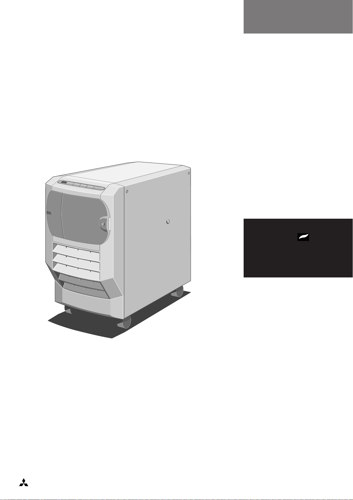
Shogun
apricot
MITSUBISHI ELECTRIC

OWNER’S HANDBOOK

Adaptec is a registered trademark and ATA is a trademark of Adaptec Inc.
Cirrus Logic is a trademark of Cirrus Logic Inc.
Hercules is a registered trademark of Hercules Computer Technology Inc.
Intel is a registered trademark, and Pentium is a trademark, of Intel Corporation.
Microsoft, MS-DOS are registered trademarks, and Windows and Windows NT are
trademarks, of Microsoft Corporation.
Novell and NetWare registered trademarks of Novell Inc.
OS/2 and VGA are trademarks of International Business Machines Corporation
SCO and MPX are trademarks of Santa Cruz Operation Inc.
SIMM is a registered trademark of Wang Laboratories.
UNIX is a registered trademark of UNIX System Laboratories Inc.
Other trademarks are the properties of their respective owners.
Information contained in this document is subject to change without notice and does not
represent a commitment on the part of Apricot Computers Limited. Any software
described in this manual is furnished under a license agreement. The software may be used
or copied only in accordance with the terms of this agreement. It is against the law to
copy any disk supplied for any other purpose than the purchaser’s personal use.
All rights reserved; no use or disclosure without written consent.
Copyright © Apricot Computers Limited 1995
Published by:
Apricot Computers Limited
3500 Parkside
Birmingham Business Park
B37 7YS
MITSUBISHI ELECTRIC
Printed in the United Kingdom

Safety and Regulatory Notices
Safety and Regulatory Notices
Read the separate Power Connection Guide before using the computer for
the first time. Information in the Owner’s Handbook relating to connection
to the AC power supply may not apply outside the United Kingdom.
The computer uses a safety ground and must be earthed. The system unit
AC power cord is its “disconnect device”. Ensure that the system unit is
positioned close to the AC power outlet, and that the plug is easily
accessible.
The power supply automatically sets itself to the appropriate voltage;
there is no voltage selector switch. However, it is advisable to avoid
subjecting the power supply to voltages outside the ranges 85-132V and
180-264V.
To prevent fire and electric shock, do not expose any part of the
computer to rain or moisture.
Turn off the computer and unplug all power cords before moving the
system unit, cleaning the computer or removing the side panels. An
exception to this is removing the side panels before hot-plugging a hard
disk drive.
When positioning the system unit, monitor and keyboard, take into
account any local or national regulations relating to ergonomic
requirements.
The CD-ROM drive contains a laser system which is harmful to the eyes,
and is classified as a CLASS 1 LASER PRODUCT according to IEC825
Radiation Safety of Laser Products (Equipment Classification:
Requirements & User's Guide). Do not attempt to disassemble the CDROM drive; if a fault occurs, call an authorized maintainer. Use the CDROM drive only as described in this manual; failure to do so may result in
exposure to hazardous radiation.
Warning:
This product contains a replaceable lithium battery. Do not use a metal or other
conductive implement to remove the battery. If a short-circuit is accidentally made
between its positive and negative terminals, the battery may explode. Replace a
discharged battery with one of the same type; another type may explode or ignite.
Dispose of a discharged battery promptly and in accordance with the manufacturer’s
instructions. Do not recharge, disassemble or incinerate. Keep away from children. If
in any doubt, contact your supplier or an authorized maintainer.
OWNER’S HANDBOOK I

Safety and Regulatory Notices
Power cord requirements
The power cord packed with the computer complies with the safety
standards applicable in the country in which it is first sold. Use only this
power cord; do not substitute a power cord from any other equipment.
If you wish to use the computer in another country, you must ensure that
you use a power cord and plug which complies with the safety standards
of that country.
BS1363A
250V
E
LN
United Kingdom
SHUCO
250V
Austria, Belgium, Finland,
E
NL
France, Germany, Holland,
Italy, Norway, Sweden
NEMA 5-15P
125V
E
N
L
Taiwan, Thailand
The power cord fittings must bear the certification mark of the agency
responsible for evaluation. Refer to your authorized supplier if you ever
need additional or alternative power cables.
II OWNER’S HANDBOOK
UK plug wiring instructions
IMPORTANT:
Power Cable
Connections
This equipment is supplied with a mains
lead that has a non-removable moulded
plug. If the socket outlets are not suitable
for the plug supplied with this appliance,
it should be cut off and an appropriate
three-pin plug fitted.
Note: The plug severed from the mains
lead must be destroyed, as a plug with
the bared flexible cord is hazardous if
engaged in a live socket outlet.
The following wiring information should
be employed when adding the replacement plug.
The wires in the mains lead are coloured
in accordance with the following code:
Green and Yellow Earth
Blue Neutral
Brown Live
As the colours of the wires in the mains
lead of this appliance may not correspond
with the coloured markings identifying
the terminals in your plug, proceed as
follows.
Safety and Regulatory Notices
The wire which is coloured green-andyellow must be connected to the
terminal in the plug which is marked with
the letter E, or by the earth symbol
or coloured green or green-and-yellow.
The wire which is coloured blue must be
connected to the terminal which is
marked with the letter N or coloured
black. The wire which is coloured brown
must be connected to the terminal which
is marked with the letter L or coloured
red.
Use a fuse approved to BS1362, i.e. one
which carries the
replace the fuse with one of the same
type and rating.
Always replace the fuse cover, never use
the plug with the fuse cover omitted.
Replace with same colour fuse cover only.
Replacement fuse covers may be
obtained from your dealer.
ASA
or mark. Only
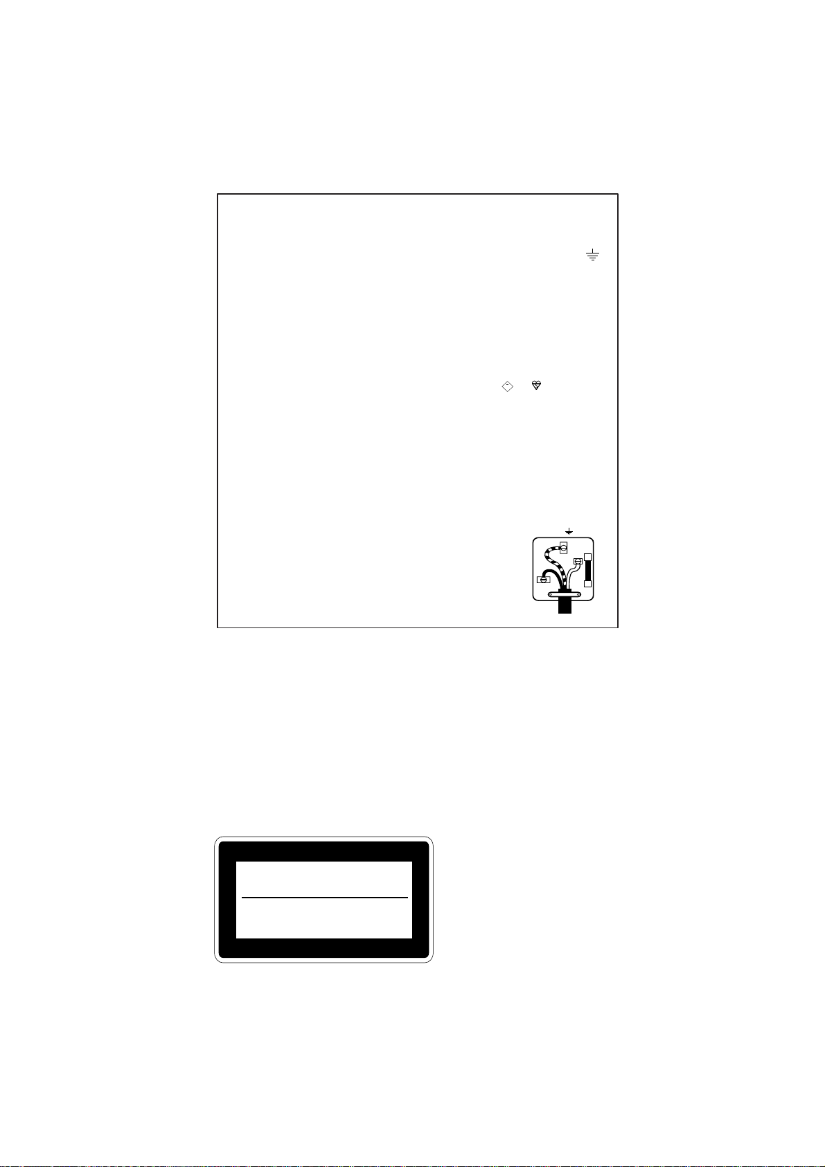
WARNING: THIS APPLIANCE
MUST BE EARTHED
This diagram shows
the wiring inside the
moulded plug. Use it
as a guideline if you
need to re-fit a plug
of a similar type to
the mains lead.
E
L
N
German Acoustic Noise Regulation
Sound power level is less than 70 dB(A) according to DIN 45635 Part 19
(ISO 7779).
Die Deutsche Akustische Lärm-Regulierung
Der Grad der Klangstärke ist weniger als 70 dB (A) je nach DIN 45635
Teil 19 (ISO 7779).
The CD-ROM drive is
classified as a CLASS 1
CLASS 1
LASER PRODUCT TO IEC 825
LASER KLASS 1
PRODUKT NACH IEC 825
LASER PRODUCT. The
CLASS 1 LASER
PRODUCT label is located
on the under side of the
system unit.
OWNER’S HANDBOOK III

Safety and Regulatory Notices
Refer to the labels on the rear of the computer to establish which of the following
warnings apply.
FCC Class A
Warning - this equipment has been tested and found to comply with the limits for a Class
A computing device, pursuant to Subpart J of Part 15 of FCC rules. Only peripherals
(computer input/output devices, terminals, printer, etc.) certified to comply with the Class
A limits may be attached to this computer. Operation of this equipment in a residential
area may cause unacceptable interference to radio and television reception requiring the
operator to take whatever steps are necessary to correct the interference.
FCC Class B
Warning - this equipment has been certified to comply with the limits for a Class B
computing device, pursuant to Subpart J of Part 15 of FCC rules. Only peripherals
(computer input/output devices, terminals, printer, etc.) certified to comply with the Class
B limits may be attached to this computer. Operation with non-certified peripherals is
likely to result in interference with radio and TV reception.
Radio and television interference
The computer described in this manual generates and uses radio frequency energy for its
operation. If it is not installed and used properly, in strict accordance with the manual, it
may cause interference with radio and television reception.
The computer has been tested and found to comply with the RF emission limits for an
FCC Class B computing device which is intended to provide reasonable protection against
such interference in a residential installation. However, there is no guarantee that
interference will not occur in a particular installation.
If this equipment does cause interference with radio or television reception, which can be
determined by turning the equipment off and on, the user is encouraged to try to correct
the interference by one or more of the following measures:
♦ Move the computer away from the receiver being interfered with.
♦ Turn the computer with respect to the receiver.
♦ Turn the receiver with respect to the computer.
♦ Plug the computer into an outlet that is on a different branch circuit from the
receiver.
♦ Disconnect and remove any I/O cables that are not being used.
♦ Unplug and remove any expansion cards that are not being used, and replace the
relevant blanking plates.
♦ Make sure that the computer is plugged into a grounded outlet.
If you need additional help, consult your supplier. You may find the following booklet
helpful: How to Identify and Resolve Radio-TV Interference Problems. This booklet is
available from the US Government Printing Office: Washington DC 20402 - Stock No.
004-000-000345-4.
DOC Class A
The computer described in this manual complies with: Canadian DOC radio interference
regulations CRCc 1374 governing Class A digital devices.
DOC Class B
The computer described in this manual complies with: Canadian DOC radio interference
regulations CRCc 1374 governing Class B digital devices.
IV OWNER’S HANDBOOK

CONTENTS
Introduction
System Overview and Features 1/1
Structure of the Owner’s Handbook 1/3
Operating Your System
Front View 2/1
Rear Panel 2/3
Machine Interior 2/4
Setting Up Your System for the First Time 2/7
Using the Front Panel 2/8
Security 2/11
Automatic Failure Recovery 2/12
Using the System Configuration Utility 2/12
The Flash Memory 2/17
Upgrading Your System
Gaining Access to the Machine Interior 3/1
Installing a CPU Card 3/4
Adding Memory 3/7
Installing Expansion Cards 3/10
Fitting Hard Disk Drives 3/12
Service Information
Preliminary Service Tasks 4/2
Antistatic Precautions 4/2
Equipment Required 4/2
Hard Disk Drive 4/3
Hard Disk Drive Module 4/7
Front Bezel 4/13
Front Panel 4/15
Removable Media Drives 4/20
OWNER’S HANDBOOK I

Contents
System Management Controller Board 4/25
Cooling Fan and Handguard 4/30
Hard Disk Drive Cooling Fan Assembly 4/32
Hard Disk Drive Module Backplane 4/36
Motherboard Power Distribution Panel 4/39
Motherboard 4/41
Motherboard Cooling Fan Assembly 4/47
Hard Disk Drive Power Distribution Panel 4/49
Removable Media Drive Bay Power Distribution Panel 4/53
Loudspeaker 4/55
Uninterruptible Power Supply Unit 4/59
UPS Battery Pack 4/68
Technical Information
Functional Architecture 5/2
Memory 5/4
Central Processing Unit 5/6
Motherboard 5/9
Switches and Jumpers 5/15
I/O Connectors and Headers 5/22
System Management Controller 5/50
Power Distribution Boards 5/51
Uninterruptible Power Supply 5/52
Appendix Antistatic Precautions
Glossary
II OWNER’S HANDBOOK
1 INTRODUCTION
Your Apricot is a high-performance, reliable and upgradeable network
server. It is designed for use in large and complex networks in which
speed, large storage capacity and robustness are essential.
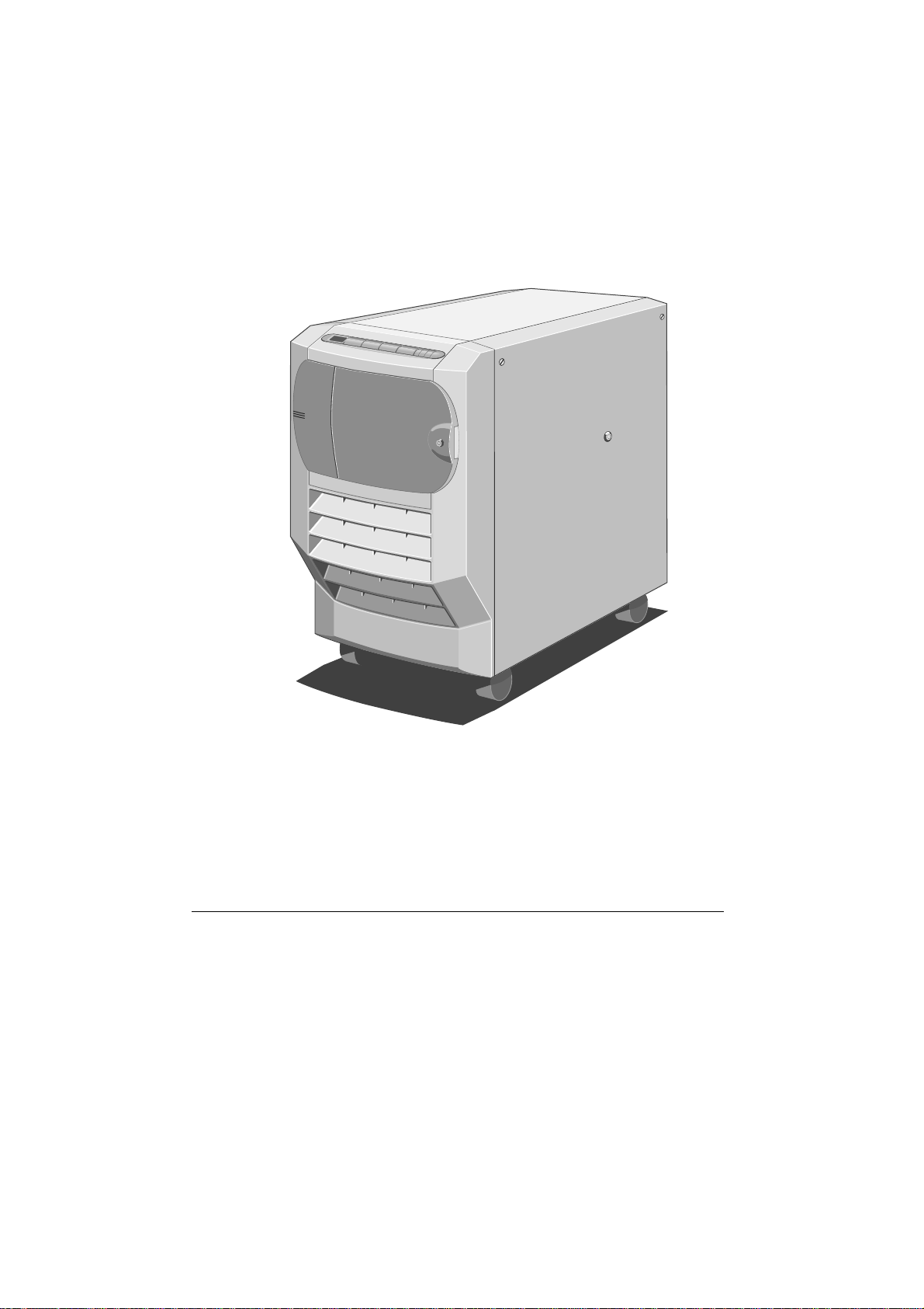
Figure 1-1 Shogun System Unit
This chapter gives you an overview of the system and its features. It also
explains briefly how the information in the Owner’s Handbook is
organized.
System Overview and Features
Your Apricot is a fully symmetrical multiprocessor system that can be
expanded and adapted according to your needs. The system will support:
♦ One to four 100-MHz Pentium processors, via single or dual
processor cards.
♦ 768 Mbytes of Error Checking and Correcting (EEC) memory via
two memory cards.
♦ 20 multi-Gbyte hard disk drives. These drives are connected to a
semi-rigid backplane, thus minimising the connector stress that
drive vibration can cause.
OWNER’S HANDBOOK 1-1

Introduction
Other features include:
♦ Multi-processor Bus. The system is equipped with a chipset that
controls a multiplexed 64-bit bus and achieves a peak transfer rate
of 267 Mbytes per second at 33 MHz. It also provides an integrated
1.2 Mbyte cache and an intelligent PCI bridge.
♦ Fault resilience, rather than just fault tolerance, provided by RAID
technology (RAID = Redundant Arrays of Independent Disks). This
supports automatic intelligent system reconfiguration after failure
and hot swapping of hard disk drives.
♦ Systems Management Controller (SMC), which monitors the system
and reports any problems. It allows remote diagnostics and
maintenance without requiring a working main CPU or rebooting
the system into diagnostics mode. There is also the System
Management Application (SMA) which is the software interface
between you and the controller. You can run the SMA via a direct
serial link to another PC, via a modem link to a computer at another
site or over the network itself.
♦ PCI Peer Bus Architecture, which achieves a 128 Mbytes/second
peak transfer rate through each of two 32-bit PCI buses. This is the
main I/O bus in the system. There are 4 slots, two of which are
shared with EISA slots.
♦ EISA Bus, which provides compatibility for lower performance add-
in cards. There are 6 slots, two of which are shared with PCI slots.
♦ 1000-watt Uninterruptible Power Supply. This is a robust unit with
a removable battery pack, external battery isolation switch and
standby power for the SMC.
♦ Network environments. The server will run all the major network
environments such as Novell NetWare, UnixWare, Windows NT
and SCO UNIX & MPX.
♦ One 3.5-inch 1.44-Mbyte floppy disk drive.
♦ One 5.25-inch CD-ROM drive.
♦ 102-key extended PS/2 keyboard.
♦ 2-Button PS/2 mouse.
1-2 OWNER’S HANDBOOK

Introduction
Structure of the Owner’s Handbook
The information in the Owner’s Handbook is divided into the following
parts:
Operating Your System - This section explains the use of the Front
Panel Controls. It also contains information about back panel functions
and ports, security aspects and the System Configuration Utility.
Upgrading Your System - This section shows you how to install
additional memory, processors, expansion cards and hard disk drives.
Service Information - This section contains detailed information for an
authorized engineer about what to do if something goes wrong with the
system. Instructions for removing the motherboard and the SMC board,
replacing faulty hard disk drives and drive modules, removal and refitting
of cooling fans, removal and refitting of the UPS and the associated
battery pack are included.
Technical Information - This section contains pin-out details as well as
information about memory, electronics and circuitry.
Appendix - The Appendix contains information about antistatic
precautions.
Glossary - The glossary defines important concepts and terms specific to
the server and its features.
OWNER’S HANDBOOK 1-3
2 OPERATING YOUR SYSTEM
SLOT-4
DC
Write Protect
Step
Cassette
Drive
Open/Close
C
O
M
P
A
C
T
10
9
11
12
13
14
16
8
7
6
5
4
3
2
1
15
This section identifies the different parts of your system, explains what
you should do when using the system for the first time and shows you
how to carry out tasks which are part of normal operation.
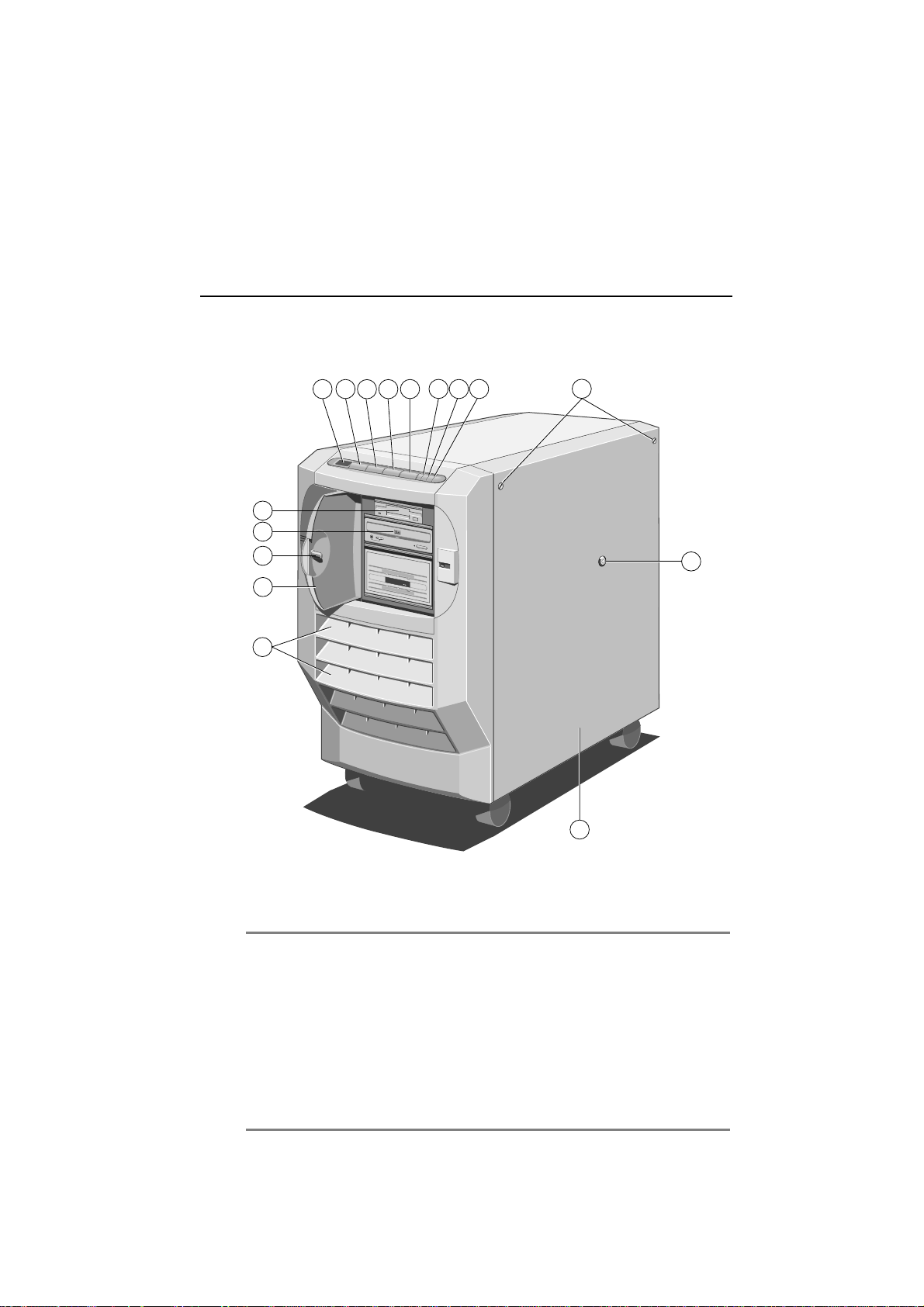
Front View
The following illustration shows a front view of the server with the drive
bay door open:
Figure 2-1 Front View
1. Diagnostic Codes LCD 9. 3.5” Floppy Drive
2. P
3. C
4. S
5. R
OWER ON
ONTROL
TANDBY
ESET
Button 10. 5.25” CD ROM Drive
Button 11. Drive Bay Door Keylock
Button 12. Drive Bay Door
Button 13. Air Intake Vents
6. Infrared Sensor 14. Removable Side Panel
7. UPS LED 15. Side Panel Keylock
8. Power LED 16. Side Panel Floating Fasteners
OWNER’S HANDBOOK 2-1

Operating Your System
The following paragraphs explain each item on the front of the machine:
♦ Diagnostic Codes LCD - Displays diagnostic codes that indicate
errors or normal stages in the boot process (see the separate
document Diagnostic Codes Reference Guide).
♦ P
OWER ON button - Pressing this button switches the machine
from Standby mode to On mode.
♦ S
TANDBY
button - Holding this button down powers down the
server from On mode to Standby mode. This button also has special
functions in conjunction with other buttons (see Special Button
Functions later in this chapter).
♦ C
ONTROL button - Pressing this button silences alarms which
sound because of internal errors. It also has special functions in
conjunction with other buttons (see “Special Button Functions” later
in this chapter).
♦ R
ESET button - Performs a hard reboot of the system. This button
also has special functions in conjunction with other buttons (see
“Special Button Functions” later in this chapter).
♦ P
OWER LED - Indicates whether the server is On or is in Standby
mode.
♦ UPS LED - Indicates whether the system is receiving power from
the battery pack or from the mains electricity supply. It also
indicates the status of the battery pack.
♦ Lockable drive bay door - Provides security against unauthorized
access to the removable media drives. The key to this door serves as
the token used to control the built-in security subsystem (see
“Security” later in this chapter).
♦ Air Intake Vents - Openings in the front bezel through which the
system draws air in order to prevent overheating. These must not be
blocked or restricted in any way.
♦ Removable Side Panel - Provides protection for the internal
components and security against unauthorized access to the interior
of the server.
2-2 OWNER’S HANDBOOK
Operating Your System
13
6
1
2
4
7
3
5
8
12
9
11
10
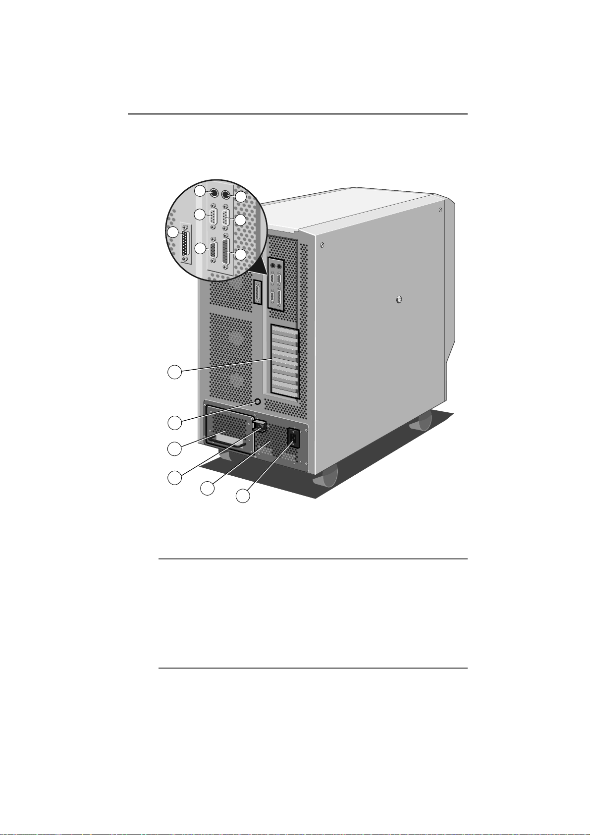
Rear Panel
The rear panel contains the various ports and connectors as shown in the
following illustration:
Figure 2-2 Rear Panel
1. Keyboard Connector (PS/2) 8. Expansion Slot Openings
2. Mouse Connector (PS/2) 9. Stud for Antistatic Strap
3. Serial Port COM2 10. Removable UPS Battery Pack
4. Serial Port COM1 11. UPS External Circuit Breaker
5. SMC Modem Port 12. Uninterruptible Power Supply
6. Video Connector 13. Mains Power Socket
7. Parallel Port
OWNER’S HANDBOOK 2-3
Operating Your System
1
2
Machine Interior
The interior of the server consists of the following main areas:
♦ Hard Disk Subsystem
♦ Removable Media Drive Bay
♦ Motherboard
♦ Systems Management Controller Board
♦ Uninterruptible Power Supply
♦ Cooling Fans
To gain access to the interior of the machine, you must remove the side
panels. Chapter 3, Upgrading Your System, contains side panel removal
instructions.
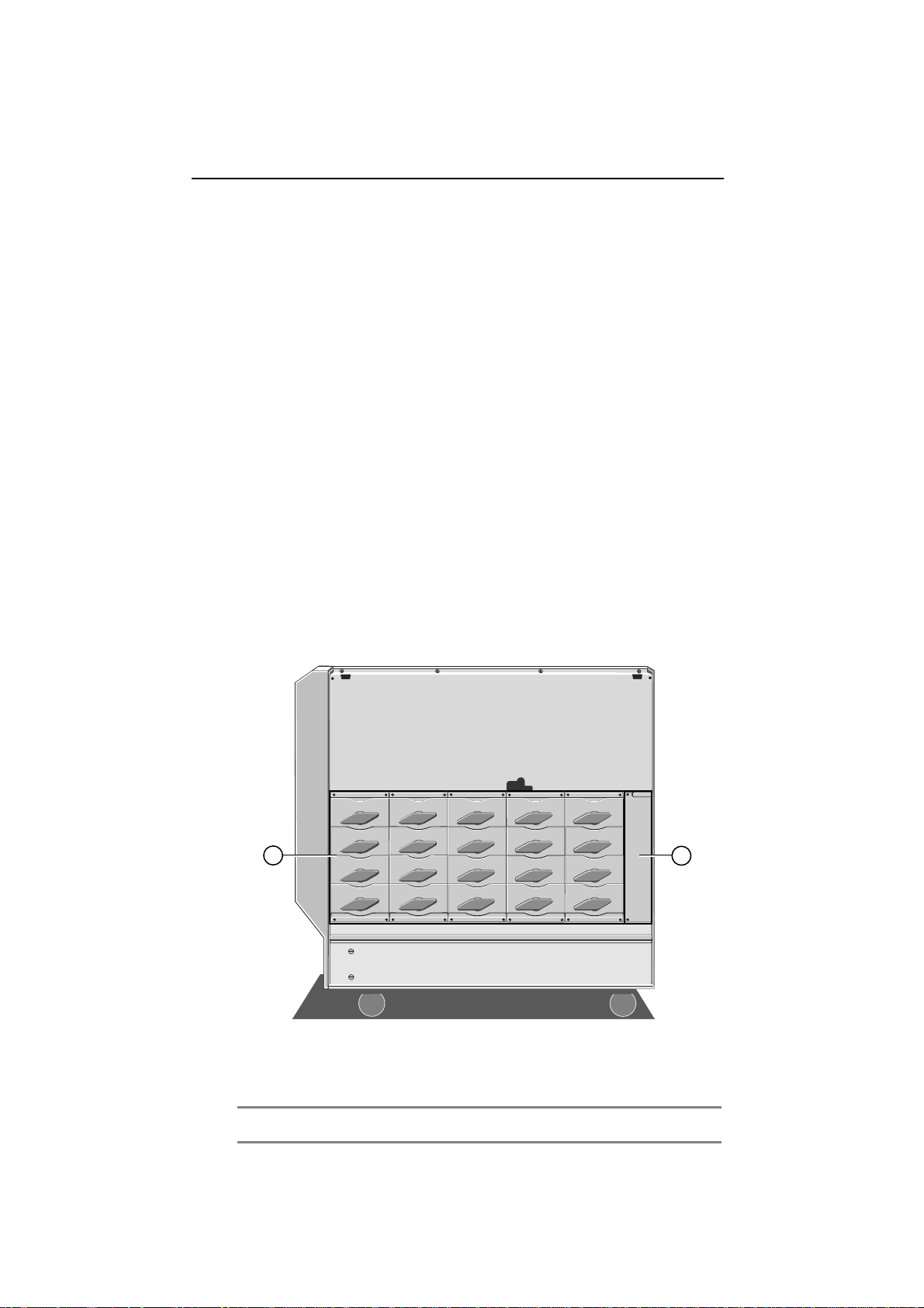
Hard Disk Subsystem
The hard disk subsystem is the area in which the hard disks are located. It
occupies the lower portion of the disk drive chamber. It will
accommodate up to 20 hard disk drives.
Figure 2-3 View of hard disk subsystem
2-4 OWNER’S HANDBOOK
1. Disk Subsystem 2. Cooling Fan Assembly
Operating Your System
Removable Media Drive Bay
The removable media drive bay is the area which contains drives such as
floppy, CD ROM and tape backup. The bay will accommodate up to four
half-height 5.25-inch drives. Your system will contain at least one 3.5inch 1.44-Mbyte floppy disk drive.
User access to the drive bay is through the lockable drive bay door on the
front bezel. The lock on the door is fitted with a sensor which, when
security is enabled, sounds an alarm if the door is opened without using
the key to unlock it.
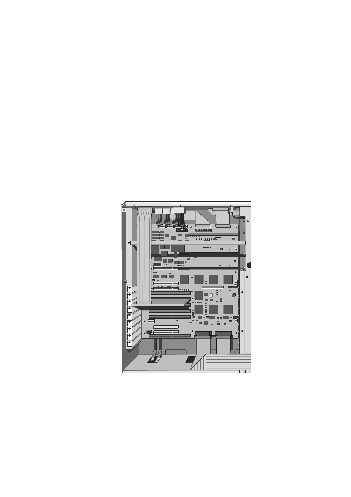
Motherboard
The motherboard contains the various disk controllers and other
electronics necessary to control the server’s functions. It contains the
memory and processing slots as well as PCI and EISA expansion slots.
Figure 2-4 Motherboard
OWNER’S HANDBOOK 2-5

Operating Your System
Uninterruptible Power Supply
This power supply is designed to keep your system powered up for a
limited period of time after a power failure. It is equipped with an on-line
removable battery pack and will give you enough time to shutdown the
network and the server without losing valuable data. The power supply,
including the battery pack, occupies the entire lower level of the server
chassis.
The UPS will maintain power to the system for a minimum of 4 minutes
in a fully-laden system, i.e. equipped with 20 hard disk drives. This time
will be longer in a system equipped with fewer drives.
Note
In the event that the mains power fails, the LCD will display a countdown of the
number of seconds remaining until the battery pack is fully discharged. The Event
Manager User’s Guide contains more details about this feature.
Cooling Fans
Your Apricot is equipped with six large cooling fans, three on each side
of the machine. These will prevent overheating by maintaining an
appropriate temperature inside the system.
In addition there are two cooling fans within the UPS unit.
Caution
You must maintain at least 15 cm space around the server for ventilation. Otherwise
damage could result from overheating.
2-6 OWNER’S HANDBOOK

Operating Your System
Setting Up Your System for the First Time
After you have unpacked the server, rolled it into position and used the
jacking mechanism on the front castors to immobilize it (see the separate
document Getting Started), use the following steps to set up the system:
1. Connect the monitor, keyboard, mouse and mains power cables to
the sockets on the server’s backplane.
2. Establish the appropriate link which will enable you to run the
System Management Application (SMA), such as:
− Direct link to another PC. In this case, use the supplied serial-
to-PC cable to connect the SMC modem port to the serial port
on the separate diagnostic computer.
− Modem link to a computer at another location. Use the
supplied serial-to-modem cable to connect the SMC port to the
modem.
− You can also run the SMA over the network itself.
3. Switch the mains socket on. The Uninterruptible Power Supply LED
should display steady green (battery fully charged) or flash green
(battery pack is charging). If the LED is flashing, it will take a
maximum of 36 hours to charge the batteries from full discharge.
The system is now in Standby mode.
4. Press the P
OWER ON button to switch the machine on.
OWNER’S HANDBOOK 2-7
Operating Your System
8
7
6
5
4
3
2
1
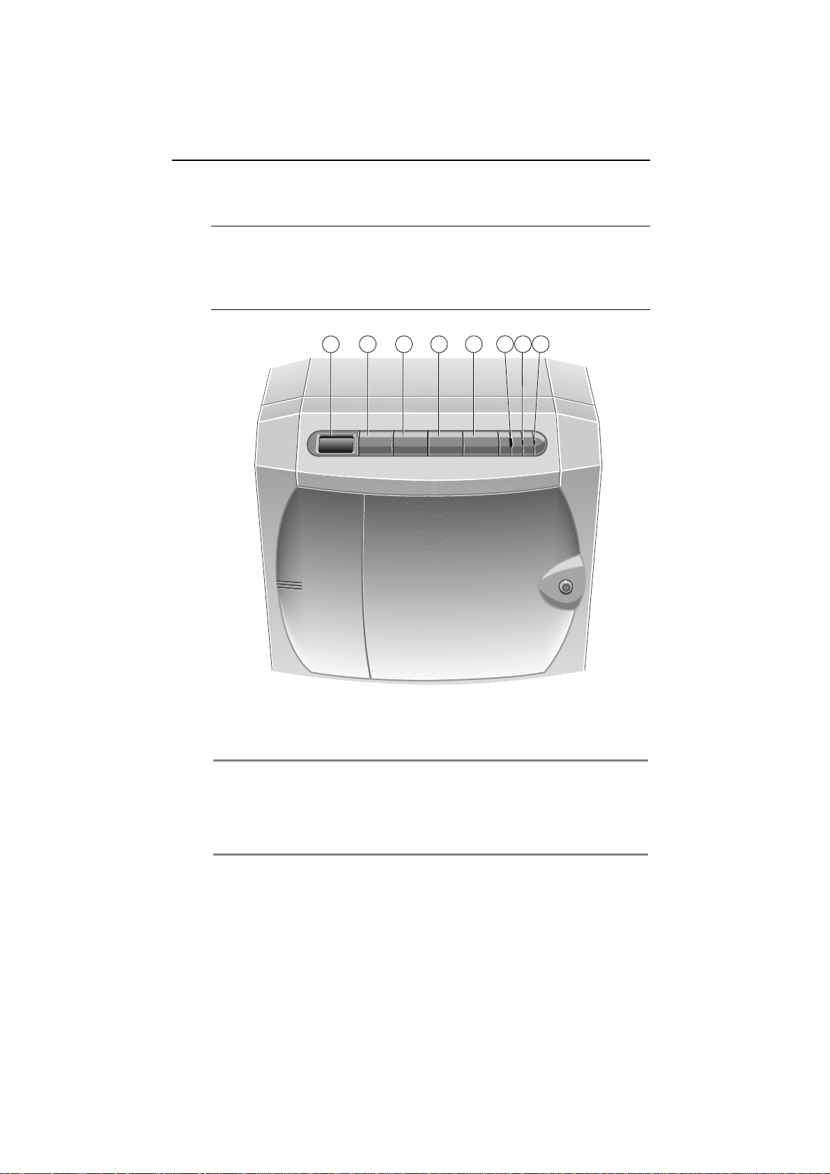
Using the Front Panel
This section describes the functions of the front panel during normal
operation.
Note
Do not place any weight, either by leaning or by placing objects, on the fascia
surrounding the front panel. Otherwise you may inadvertently press one or more of
the front panel buttons.
Figure 2-5 Front Panel Controls
1. Diagnostic LCD 5. Reset Button
2. Power On Button 6. Infrared Sensor
3. Control Button 7. UPS LED
4. Standby Button 8. Power LED
Buttons
OWER ON - Press this button to switch the system on from
♦ P
Standby mode. The Power LED will light up and the system will
initiate its boot sequence. Diagnostic codes, expressed as
hexadecimal numbers, will appear as a matter of course on the LCD
screen on the Front Panel (see the separate document Diagnostic
Codes Reference Guide for details). The screen will display the SCSI ID
2-8 OWNER’S HANDBOOK

Operating Your System
number for each of the SCSI devices installed in your system. What
happens after this depends on how your Apricot has been
configured, i.e. which operating system or other software may be
installed. Check with your supplier if you need more details.
♦ S
TANDBY - After you have instructed all network users to close their
applications down and log off the network, hold this button down
for a specific period of time before the system initiates a shutdown
sequence to Standby mode. The system will display the code 1200
on the LCD and sound a tone. Continue to hold down the S
button until the tone stops, at which time the shutdown sequence
begins. In Standby mode, the mains electricity supply keeps the
battery pack fully charged, but there is no DC power supplied to the
system. Use the System Management Application (SMA) to specify,
in seconds, how long you must hold down the button before the
shutdown sequence begins (see the SMA User’s Guide). The default is
3 seconds.
TANDBY
Press S
TANDBY
and C
ONTROL
simultaneously to cancel the current
shutdown sequence.
Note
It is good practice to warn anyone who may be accessing the system remotely,
i.e. using the SMA from a remote computer via the modem port, before you
press the S
♦ CONTROL
TANDBY button.
- Press this button to silence alarms and clear LCD
display codes that are produced because of internal errors and power
failures (but not security alarms).
Pressing C
ONTROL at the end of firmware initialization forces the
System Management Controller (SMC) to execute the code of the
EPROM instead of the Flash ROM, even if the version in the Flash
is newer than that of the EPROM. This allows you to boot from
EPROM if there is something wrong with the Flash code.
♦ R
- Press this button to initiate a hardware reset, but only if it is
ESET
absolutely necessary. The LCD will display 1400. You must hold
the button down until the accompanying tone stops sounding. Use
the System Management Application (SMA) to specify how long, in
seconds, the reset tone will sound (see the SMA User’s Guide). The
default is 3 seconds.
Press R
ESET
and C
reset sequence.
ONTROL
simultaneously to cancel the current
OWNER’S HANDBOOK 2-9

Operating Your System
Special Button Functions
Caution
Do not use these functions unless there is serious problem with the system and it is
absolutely necessary.
Pressing STANDBY, CONTROL and RESET simultaneously while the front
drive bay door is unlocked switches the system into a mode in which
these three buttons have special functions. The LCD displays 8888 to
indicate this mode. The following paragraphs describe the special
function of each button.
♦ S
TANDBY or RESET - Pressing either of these buttons initiates a
memory dump to the central processing unit by activating and then
deactivating the Non-Maskable Interrupt (NMI) signal via the
diagnostic processor. The effect of this action will depend on the
operating system. You can then use the appropriate function of the
network operating system to examine the contents of the dump.
♦ C
ONTROL
- Pressing this button initializes the modem, which is
connected to the SMC modem port on the back panel of the server.
If the modem initialization is successful, the LCD displays the code
0000. If the initialization is unsuccessful, the LCD displays 0F4D or
0F4E.
♦ S
TANDBY
+ R
- Pressing these buttons simultaneously clears the
ESET
LCD and then releasing them executes an independent SMC reset.
This would only be necessary if a major problem or error had
occurred in the system, which is unlikely.
If you do not press any buttons for ten seconds, the system returns to
normal mode.
UPS and Power LEDs
The UPS and Power LEDs indicate the state of the system as follows:
UPS LED
♦ When this LED shows steady green, it means that the system is
powered by mains electricity and the batteries are fully charged.
♦ Flashing green means that system is powered by mains electricity
and the batteries are in the process of charging. This will usually be
the case after the system has been without mains electricity, i.e.
disconnecting the plug or a power failure.
♦ Steady amber indicates that the system is drawing its power off the
batteries, i.e. there is no mains electricity. As soon as mains
electricity fails, an alarm sounds.
2-10 OWNER’S HANDBOOK

Operating Your System
♦ Flashing amber indicates that the battery pack is about to fail.
♦ Off shows that the batteries are disconnected because the circuit
breaker switch on the back of the machine is in the Off position or
the system is disconnected from the mains.
Power LED
♦ Steady green means that the system is on.
Security
Your Apricot is equipped with a security system to help prevent
unauthorized persons tampering with the front panel buttons and gaining
access to the interior of the system.
Security is enabled within the System Management Application (see the
SMA User’s Guide, the Event Manager User’s Guide or the on-line help within
the SMA software). Once security is enabled, the key to the removable
drive bay door at the front of the machine serves as the security token:
♦ If the door is closed and has been locked with the key, the screen is
blanked, the keyboard is disabled, the security alarm is activated and
will sound if there is a violation.
♦ Unlocking the door unblanks the screen, enables the keyboard and
deactivates the security alarm.
Note
When security is enabled and the door locked, you can use the KeyLOC infrared
card to unblank the screen and enable the keyboard temporarily. The card will also
silence a security alarm. Use the card again to blank the screen and disable the
keyboard.
The following actions are security violations and will set off the alarm
when the drive bay door is closed and locked and security is enabled:
♦ Forcible opening (i.e. without the key) of the removable drive bay
door.
♦ Removal, with or without the key, of one or both of the side panels.
♦ Pressing the S
TANDBY, CONTROL or RESET buttons individually or
in any combination.
To silence the alarm, use the key to unlock the drive bay door. If the
door is already unlocked when the alarm sounds, first lock and then
unlock the door.
Alternatively, use the KeyLOC card to silence the alarm.
OWNER’S HANDBOOK 2-11

Operating Your System
Automatic Failure Recovery
As with any computer system, your server may develop a hardware or
software fault, which, for example, may only manifest itself intermittently,
that causes the system to hang. If this happens, the server is capable of
resetting itself automatically. This is particularly useful if the server is
unattended some or all of the time.
Whether the server is able to rebuild the complete network environment,
together with application programs, after an automatic reset depends on
the operating system. The SMA contains several variables which govern
the behaviour of automatic failure recovery:
♦ Machine Status
♦ Watchdog Timeout
♦ Watchdog Timer Reboot Count
♦ Watchdog Timer Timeout Action
You can make settings for these variables to enable, disable or modify
their effects. The on-line Help system within the SMA contains details of
all of these variables and how to make the appropriate settings.
Using the System Configuration Utility
The System Configuration Utility (SCU) automates the configuration
process for your computer’s hardware and the boards (ISA, EISA, Plug-nPlay and PCI) or options that you add to the system. You must run the
SCU each time you change your computer’s configuration. Running the
SCU is optional for Plug-n-Play and PCI add-in boards. The SCU does
the following:
♦ Maintains system parameters and stores these in non-volatile RAM.
♦ Presents the option settings that specify those parameters.
♦ Assigns all necessary system resources, which guarantees that there
will be no conflicts or contention issues between adapter cards.
♦ Presents settings for many other functions, such as security
passwords, that are necessary or desirable.
Note
Although there is a separate BIOS Setup utility, only use the SCU to configure your
system, as BIOS Setup is not accessible to a remote computer.
2-12 OWNER’S HANDBOOK
Operating Your System
To run the SCU:
Locally, press F2 to run the Flash Disk Utility during the hardware boot
sequence but before the operating system loads; remotely, run the Flash
Disk Utility via the SMA. You also can use the SMA to instruct the system
to load the SCU automatically (see the SMA User’s Guide). The Flash Disk
Utility menu then appears on the screen.
1. Select “Run Configuration Utility” from the Flash Disk Utility menu.
2. At this point a further submenu appears. Choose one of the options
according to the following guidelines:
− Choose “Run SCU” as the preferred option.
− Since the SCU is limited to 640K base memory, there may not
be enough memory to load it plus all the configuration (.CFG)
files associated with the motherboard and the expansion cards
installed in your system. Your system will inform you if there is
insufficent memory. If this should happen, which is unlikely,
choose one of the other options in the submenu as an
alternative. “Run SCU (Motherboard)” excludes the expansion
card configuration files, thereby freeing memory. “Run SCU
(EISA/PCI)” does the same, but this time excludes the
motherboard configuration file to free memory.
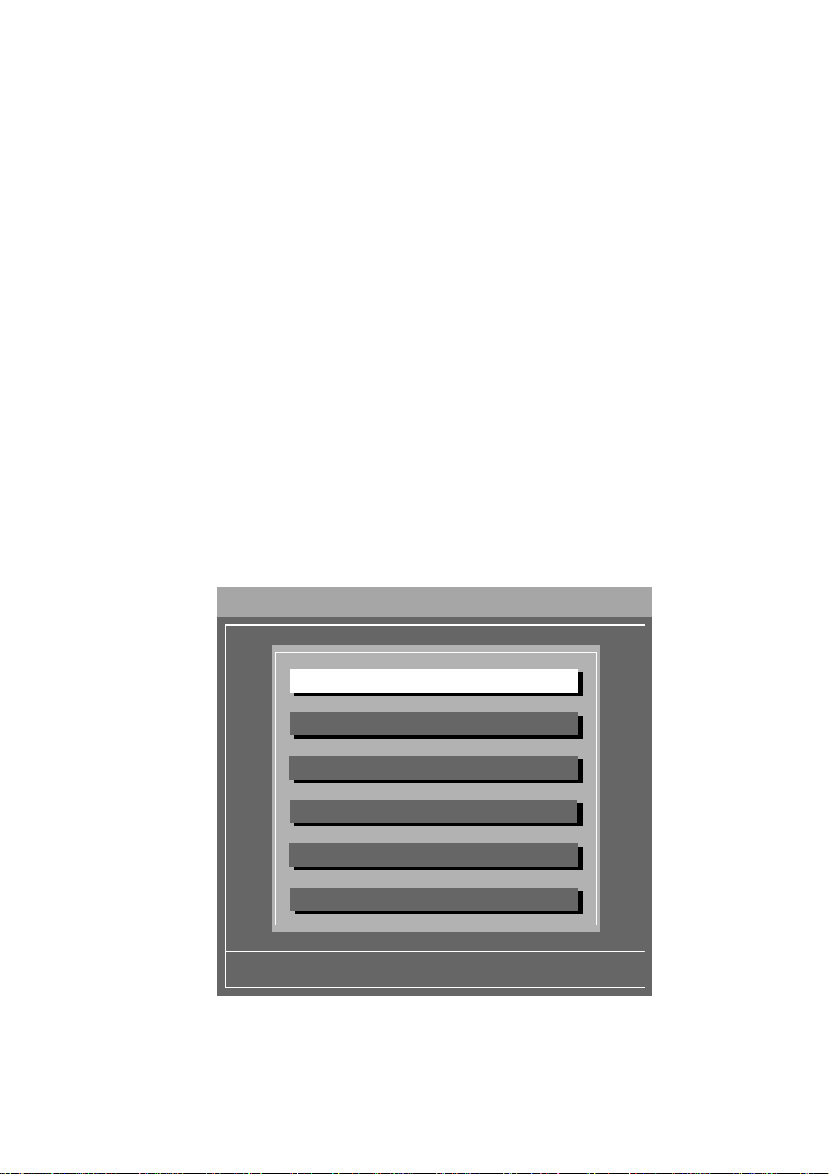
The following menu then appears:
System Configuration Utility (C) 1995 American Megatrends Inc.
Step 1: About System Configuration
Step 2: Add and Remove Boards
Step 3: Change Configuration Settings
Step 4: Save Configuration
Step 5: View Switch/Jumper Settings
Step 6: Exit
OWNER’S HANDBOOK 2-13

Operating Your System
How to use the SCU
The Help text will provide most of the instructions you will need to use
the SCU. The following paragraphs briefly explain the general techniques
for navigating your way through the utility.
Using menus and selection screens
♦ To select an option from a menu or selection screen, use the UP or
DOWN ARROW key to move the highlight to the option and press
the ENTER key. For example, use this procedure for Steps 1-6 on
the Main Menu.
Note
The fact that the Main Menu options are listed as numbered steps does not
necessarily imply that you must select them in numerical order every time you run the
SCU. However, if you have made changes to the existing configuration, you must
select Step 4: Save Configuration before you will be able to select Step 5: View
Switch/Jumper Settings.
♦ In addition to the menu options, most screens display defined keys
at the bottom of the screen, e.g. [Select=ENTER], or [Utilities=F9].
Press a defined key to initiate its corresponding action.
♦ Some screens contain vertical scroll bars on the right-hand edge,
which indicate that there is more information than one screen can
accommodate. You can use UP or DOWN ARROW to scroll
through the information. If you need to scroll quickly through a
series of screens, use PAGE UP or PAGE DOWN.
♦ When you select Step 5: View Switch/Jumper Settings, the
screen will display information for one board at a time. Press PAGE
DOWN to advance to the next board. If all the information for a
single board cannot be accommodated on one screen, pressing
PAGE DOWN will first scroll through to the end of the information
for that board and then pressing it again will advance to the next
board. PAGE UP does the same in reverse.
♦ Some screens contain toggle options, e.g. the screen for
[Utilities=F9] from the Main Menu. To turn a toggle option on or
off, move the highlight to the option and press the SPACEBAR. A
tick mark in the square brackets indicates that the option is in force.
♦ You can also use the mouse to select options, activate defined keys
and use scroll bars. Just point with the mouse cursor on the item and
click with the left mouse button. Clicking anywhere with the right
mouse button returns to the previous screen or, if you are at the
Main Menu, exits from the SCU. You must confirm your exit by
pressing ENTER or by clicking YES with the left mouse button.
When you have returned to the main menu, a tick mark to the left of the
option indicates that you have completed that step.
2-14 OWNER’S HANDBOOK

Operating Your System
How to use SCU Help
There are two ways to access SCU Help:
♦ Select Step 1: About System Configuration, from the Main
Menu. This option displays information about the SCU.
♦ Press F1 at any time, which will give you specific information about
the current screen or dialog box.
Use the following procedures to navigate your way around the Help
screens:
♦ Press F3 on any Help screen to display a list of Help topics. Then
select, with the cursor or the mouse, one of the topics which appears
in white text.
♦ If a word or phrase appears white in the midst of the normal blue
text on a Help screen, you can select it to display a further Help
screen about that topic.
♦ Press F2 to redisplay the previous Help topic shown. Press F2
repeatedly to reverse along your route through the Help screens.
♦ Press ESC to exit from Help.
Note
On a monochrome monitor, a help topic word or phrase looks the same as the
surrounding text and is not identifiable by its appearance, in contrast to a colour
monitor. To identify a help topic, use the arrow keys to move the cursor through the
help text. The cursor will highlight only help topics.
Passwords
The purpose of the passwords is to prevent unauthorized persons from
using the computer and from changing the system configuration settings.
There are two different passwords which govern the kind of access you
have to the SCU program. You can choose to set either one or both
passwords:
♦ Administrative - This password gives you full access to all the
configuration settings including the ability to change them.
♦ User - This password gives you viewing access to the settings, but
you are not allowed to change them.
You can set both of these passwords within the SCU along with the other
system parameters. A password can be up to 7 alphanumeric characters in
length.
OWNER’S HANDBOOK 2-15

Operating Your System
The first time you run the SCU there will be no passwords in force. When
you select Step 2 or Step 3 from the Main Menu, which are the only
options in the SCU which are password-protected, the system will display
the First-Time Admin Password prompt box. This is an alternative
method to setting the Administrative password within the SCU along
with other parameters. When you see this box, do one of the following:
♦ Press ESC to bypass the box if you don’t want to set any passwords.
You now have full access to the configuration settings, including the
ability to change them. As long as you do not set a password, the
First-Time Admin Password prompt box will appear every time
you run the SCU.
♦ Type in an administrative password. Then press TAB (not ENTER)
to move the cursor to the confirm field and then type the password
again. Now press ENTER to confirm. Your administrative password
is now set.
Note
There is no such prompt box for the User Password. The only way to set this
password is within the SCU along with other system parameters.
The existence of a password imposes the following requirements or
restrictions:
♦ You must enter the password, when the system prompts you, to
complete the boot process and load the operating system. If both
passwords are set, entering either one achieves this same objective.
♦ When you run the SCU, you must enter a password at the prompt
after selecting Step 2 or Step 3 from the Main Menu. If only one
password is set, either Administrative or User, entering it gives you
full access to the configuration settings. If both passwords are set,
only the Administrative allows you to change settings. The User
password restricts you just to viewing access.
♦ You will not be able to boot the system from a remote workstation.
Password Clear Switch
There is a Password Clear Switch on the motherboard of your Apricot. If
you set this switch to On, the passwords will be cleared (i.e. removed)
every time you boot or reset the system. Unless there is a specific reason
for clearing the passwords in this way, ensure that the switch is set to Off
at all times. See Chapter 5, Technical Information, to find out where this
switch is located and how to set it.
2-16 OWNER’S HANDBOOK

Operating Your System
The Flash Memory
The Flash is a special portion of read-only memory (ROM). It differs from
conventional ROM in that its contents can be updated, but it still
preserves its information when system power is off. The following
components of your server contain their own portions of Flash memory:
♦ The motherboard - This Flash stores the BIOS information for the
motherboard.
♦ The System Management Controller - This Flash stores the BIOS
and firmware which control the SMC and the Front Panel.
♦ The System Management Interface Card (SMIC) - This is the main
Flash, also referred to as a Flash Disk. It contains bootable DOS, its
own BIOS and a Flash Disk Utility program which affects the other
portions of Flash memory. The Flash Disk Utility also runs the
System Configuration Utility (SCU).
Your access to the Flash is via a RAMdrive. This enables you to treat the
Flash almost as if it were a disk drive. The RAMdrive and the Flash Disk
each have a capacity of 2 Mbytes. Because the Flash Disk contains the
operating system files, the server can boot from it if the normal system
hard disk boot process fails. You can also copy files to the Flash Disk, e.g.
hardware component configuration (.CFG) files which the SCU uses.
The Flash Disk Utility
The reason that the RAMdrive is necessary is because the Flash Disk is
write-protected and, therefore, you cannot copy anything directly to it.
The purpose of the Flash Disk Utility is to enable updates to the
information held in any portion of Flash memory, such as new BIOS
versions or hardware information stored in the SCU.
To run the Flash Disk Utility locally, press F2 during the hardware boot
sequence but before the operating system loads. This instructs the server
to boot from the Flash Disk and load the utility. The screen then displays
a menu with the following options:
♦ Option 1, Receive File - This option copies a file from the server
to the workstation which is running the SMA. If you are not using
the SMA and are running the utility locally, the file is copied from
the Flash to a floppy disk. After you select 1 from the menu, select
the file you want to copy and press the ENTER key.
♦ Option 2, Transfer File - This option is the opposite of Receive
File, i.e. it copies a file from the SMA workstation to the server or, if
you are running the utility locally, from a floppy disk to the Flash.
♦ Option 3, Run Configuration Utility - Select this option to run
the SCU (see “Using the System Configuration Utility”, earlier in
this chapter).
OWNER’S HANDBOOK 2-17

Operating Your System
♦ Option 4, Upgrade Motherboard BIOS - This option enables
you to upgrade the motherboard’s BIOS with a new version of
BIOS information. This information is in the form of a binary file.
When you select this option, you have the choice of either copying
the binary file to the RAMdrive and updating the BIOS in one
operation or, if the correct binary file is already copied, just
performing the update.
♦ Options 5-7, i.e. Upgrade Secondary BIOS, Upgrade SMIC
BIOS and Upgrade SMC Firmware, are similar to option 4.
♦ Option 8, Upgrade Flash Disk - This option copies the contents
of the RAMdrive to the Flash Disk, thereby making the Flash
identical to the RAMdrive.
♦ Option 9, Reset Flash Disk for Upgrade - This option does the
opposite to option 8, i.e. copies the contents of the Flash to the
RAMdrive, thereby making the RAMdrive identical to the Flash.
♦ Option 10, Edit a File - Use this option to load a file into the
Microsoft Edit program for editing.
♦ Option 11, Exit - This option exits from the Flash Disk Utility and
passes control back to the SMA.
Caution
Only use Option 8 if you need to update the Flash Disk to reflect the contents of the
RAMdrive.. Only use Option 9 if the contents of the RAMdrive have become
corrupted. You must be sure of what you are doing before using these options.
2-18 OWNER’S HANDBOOK
 Loading...