

Page 1
APPLICATION NOTE
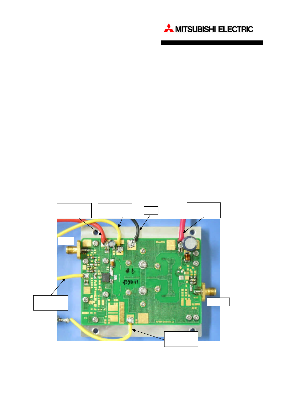
SUBJECT: RD04HMS2 & RD70HUF2 two-stage amplifier at f=380-470MHz.(Vdd=12.5V)
Features:
- The evaluation board for RD04HMS2 & RD70HUF2 two-stage amplifier
- Frequency: 380-470MHz
- Vdd: 12.5V
- Input power: 0.2W
- Output power: 79-88W
Silicon RF Power Semiconductors
Document NO. AN-UHF-122
Date : 28thFeb. 2011
Prepared : Y.Takase
S.Kametani
Confirmed :T.Okawa
(Taking charge of Silicon RF by
MIYOSHI Electronics)
- Quiescent Current: RD04HMS2 ; 0.1A, RD70HUF2 ; 1A
- Operating Current: 12-13A
- Surface-mounted RF power amplifier structure
DrainBias
(RD04HMS2)
RF IN
Gate Bias
(RD04HMS2)
Gate Bias
(RD70HUF2)
GND
Drain Bias
(RD70HUF2)
RF OUT
Gate Bias
(RD70HUF2)
PCB L=82.5mm W=60.0mm
Application Note for Silicon RF Power Semiconductors
1/17
Page 2

Contents
RD04HMS2 & RD70HUF2 two-stage amplifier at 380-470MHz. (Vdd=12.5V)
- AN-UHF-122 -
Page
1. Equivalent Circuitry ------------------------------------------------------------
2. Component List and Standard Deliverable -------------------------------------
3. PCB Layout -----------------------------------------------------------------------
4. Standard Land Pattern Dimensions -----------------------------------------
5. Typical RF Characteristics ---------------------------------------------------5-1. Frequency characteristics ------------------------------------------
5-2. Pout vs. Pin characteristics --------------------------------------------
5-3. Pout vs. Vdd characteristics ----------------------------------------5-4. Pout vs. Vgg characteristics --------------------------------------------------
3
4
6
9
10
10
12
14
16
Application Note for Silicon RF Power Semiconductors
2/17
Page 3
RD04HMS2 & RD70HUF2 two-stage amplifier at 380-470MHz. (Vdd=12.5V)
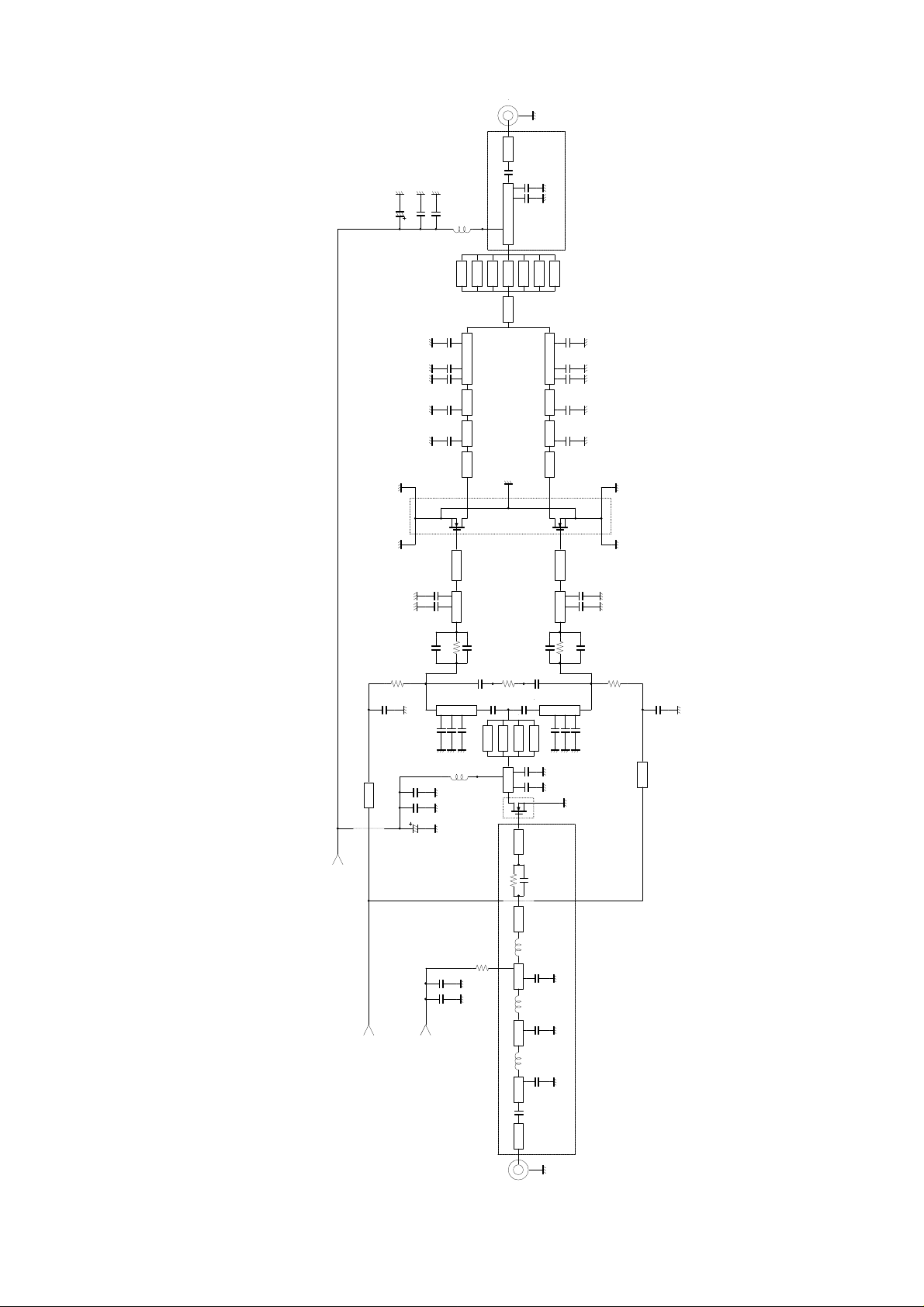
1. Equivalent Circuitry
RF OUT
ML2ML2
W=2.0W=2.0
C46
C47
C48
L5
Via
7Via holes
C34
C32
ML2
C30
ML1
C28
ML1
C26
ML1
Electrode1
Source
RD70HUF2
Electrode3
Source
C24
C22
ML1
W=4.4W=5.0
ML1
C38
C37C36
50ohm
Characteristic impidance
Via
Via
ML2
W=1.9
W=1.3
W=1.8
W=3.6
CenterSource
W=4.6
Via
Via
Via
Via
W=1.3
W=1.8
W=3.6
Electrode
W=4.6
C35
C33
ML2
C31
ML1
C29
ML1
C27
ML1
ML1
W=4.4W=5.0
C25
ML1
C23
er=4.7,TanD=0.018@1GHz
Via HoleDimensions, Diameter=0.8mmLength=1.6mm
Micro StripLine SubstrateThickness:ML1,T=0.2mm,ML2,T=1.1mm
Board material:GlassEpoxy Substrate--
Electrode2
Source
Electrode4
Source
- AN-UHF-122 -
UNIT:W [mm]
R3
C18
R6
C41
Via
1Via hole
Drain Bias
GateBias1
GateBias2
C19
C16
R2
C8
W=1.0
ML1
Via
Via
Via
4Via holes
C14
C12
C10
L4
C43 C44 C45
ML1
W=4.7
W=2.0W=2.0
R1
ML2 ML2
L3
R5
ML2
L2
C39 C40
ML2
W=2.0
L1
W=2.0W=2.0
C1
R4
C20
C17
C9
Via
C5
W=2.0
C21
R7
W=1.0
ML1
C15
C13
C11
C6 C7
C4
C3
C2
C42
Via
1Via hole
ML2 ML2
RF IN
50ohm
Characteristic impidance
Application Note for Silicon RF Power Semiconductors
3/17
Page 4
RD04HMS2 & RD70HUF2 two-stage amplifier at 380-470MHz. (Vdd=12.5V)
No.
Description
P/N
Qty
Manufacturer
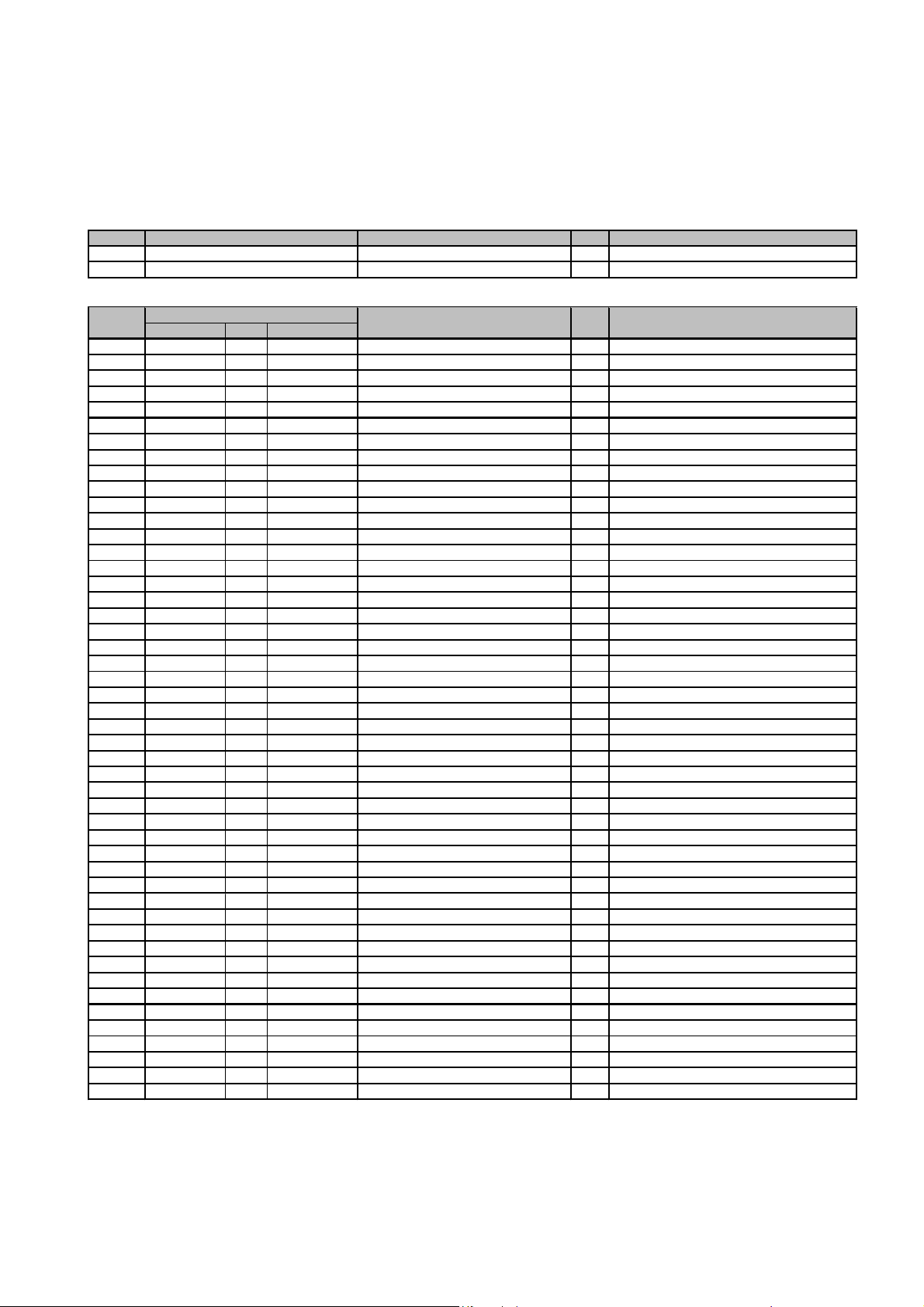
Tr1MOSFET
RD04HMS2
1
Mitsubishi Electric Corporation
Tr2MOSFET
RD70HUF2
1
Mitsubishi Electric Corporation
No.
Description
P/N
Qty
Manufacturer
Capacitance
Size
Remarks
C1100
pF
160850V
GRM1882C1H101JA01D
1
MURATA MANUFACTURING CO.
C26.2
pF
1608
Hi-Q
100
V
GQM1882C2A6R2CB01D
1
MURATA MANUFACTURING CO.
C322
pF
1608
Hi-Q50V
GQM1882C1H220JB01D
1
MURATA MANUFACTURING CO.
C436
pF
1608
Hi-Q50V
GQM1882C1H360JB01D
1
MURATA MANUFACTURING CO.
C524
pF
1608
Hi-Q50V
GQM1882C1H240JB01D
1
MURATA MANUFACTURING CO.
C627
pF
1608
Hi-Q50V
GQM1882C1H270JB01D
1
MURATA MANUFACTURING CO.
C727
pF
1608
Hi-Q50V
GQM1882C1H270JB01D
1
MURATA MANUFACTURING CO.
C8100
pF
160850V
GRM1882C1H101JA01D
1
MURATA MANUFACTURING CO.
C9100
pF
160850V
GRM1882C1H101JA01D
1
MURATA MANUFACTURING CO.
C1022
pF
1608
Hi-Q50V
GQM1882C1H220JB01D
1
MURATA MANUFACTURING CO.
C1122
pF
1608
Hi-Q50V
GQM1882C1H220JB01D
1
MURATA MANUFACTURING CO.
C1222
pF
1608
Hi-Q50V
GQM1882C1H220JB01D
1
MURATA MANUFACTURING CO.
C1322
pF
1608
Hi-Q50V
GQM1882C1H220JB01D
1
MURATA MANUFACTURING CO.
C1422
pF
1608
Hi-Q50V
GQM1882C1H220JB01D
1
MURATA MANUFACTURING CO.
C1522
pF
1608
Hi-Q50V
GQM1882C1H220JB01D
1
MURATA MANUFACTURING CO.
C16910
pF
201250V
GRM2162C1H911JA01D
1
MURATA MANUFACTURING CO.
C17910
pF
201250V
GRM2162C1H911JA01D
1
MURATA MANUFACTURING CO.
C1862
pF
2012
Hi-Q
250
V
GQM2195C2E620JB12D
1
MURATA MANUFACTURING CO.
C1962
pF
2012
Hi-Q
250
V
GQM2195C2E620JB12D
1
MURATA MANUFACTURING CO.
C2062
pF
2012
Hi-Q
250
V
GQM2195C2E620JB12D
1
MURATA MANUFACTURING CO.
C2162
pF
2012
Hi-Q
250
V
GQM2195C2E620JB12D
1
MURATA MANUFACTURING CO.
C228.2
pF
1608
Hi-Q50V
GQM1882C1H8R2CB01D
1
MURATA MANUFACTURING CO.
C238.2
pF
1608
Hi-Q50V
GQM1882C1H8R2CB01D
1
MURATA MANUFACTURING CO.
C249.1
pF
1608
Hi-Q50V
GQM1882C1H9R1CB01D
1
MURATA MANUFACTURING CO.
C259.1
pF
1608
Hi-Q50V
GQM1882C1H9R1CB01D
1
MURATA MANUFACTURING CO.
C2643
pF
2012
Hi-Q
250
V
GQM2195C2E430JB12D
1
MURATA MANUFACTURING CO.
C2743
pF
2012
Hi-Q
250
V
GQM2195C2E430JB12D
1
MURATA MANUFACTURING CO.
C2843
pF
2012
Hi-Q
250
V
GQM2195C2E430JB12D
1
MURATA MANUFACTURING CO.
C2943
pF
2012
Hi-Q
250
V
GQM2195C2E430JB12D
1
MURATA MANUFACTURING CO.
C3012
pF
2012
Hi-Q
250
V
GQM2195C2E120JB12D
1
MURATA MANUFACTURING CO.
C3112
pF
2012
Hi-Q
250
V
GQM2195C2E120JB12D
1
MURATA MANUFACTURING CO.
C3224
pF
2012
Hi-Q
250
V
GQM2195C2E240JB12D
1
MURATA MANUFACTURING CO.
C3324
pF
2012
Hi-Q
250
V
GQM2195C2E240JB12D
1
MURATA MANUFACTURING CO.
C347.5
pF
2012
Hi-Q
250
V
GQM2195C2E7R5CB12D
1
MURATA MANUFACTURING CO.
C357.5
pF
2012
Hi-Q
250
V
GQM2195C2E7R5CB12D
1
MURATA MANUFACTURING CO.
C362.7
pF
2012
Hi-Q
250
V
GQM2195C2E2R7CB12D
1
MURATA MANUFACTURING CO.
C372.7
pF
2012
Hi-Q
250
V
GQM2195C2E2R7CB12D
1
MURATA MANUFACTURING CO.
C38330
pF
3216
200
V
GRM31M2C2D331JY21B
1
MURATA MANUFACTURING CO.
C3910000
pF
160850V
GRM188B11H103KA01
1
MURATA MANUFACTURING CO.
C401000
pF
160850V
GRM1882C1H102JA01
1
MURATA MANUFACTURING CO.
C411000
pF
160850V
GRM1882C1H102JA01
1
MURATA MANUFACTURING CO.
C421000
pF
160850V
GRM1882C1H102JA01
1
MURATA MANUFACTURING CO.
C4322
μF
-50V
H1002
1
NICHICON Corporation
C4410000
pF
160850V
GRM188B11H103KA01
1
MURATA MANUFACTURING CO.
C451000
pF
160850V
GRM1882C1H102JA01
1
MURATA MANUFACTURING CO.
C46220
μF
-35V
EEUFC1V221
1
Panasonic Corporation
C47910
pF
201250V
GRM2162C1H911JA01D
1
MURATA MANUFACTURING CO.
C48910
pF
201250V
GRM2162C1H911JA01D
1
MURATA MANUFACTURING CO.
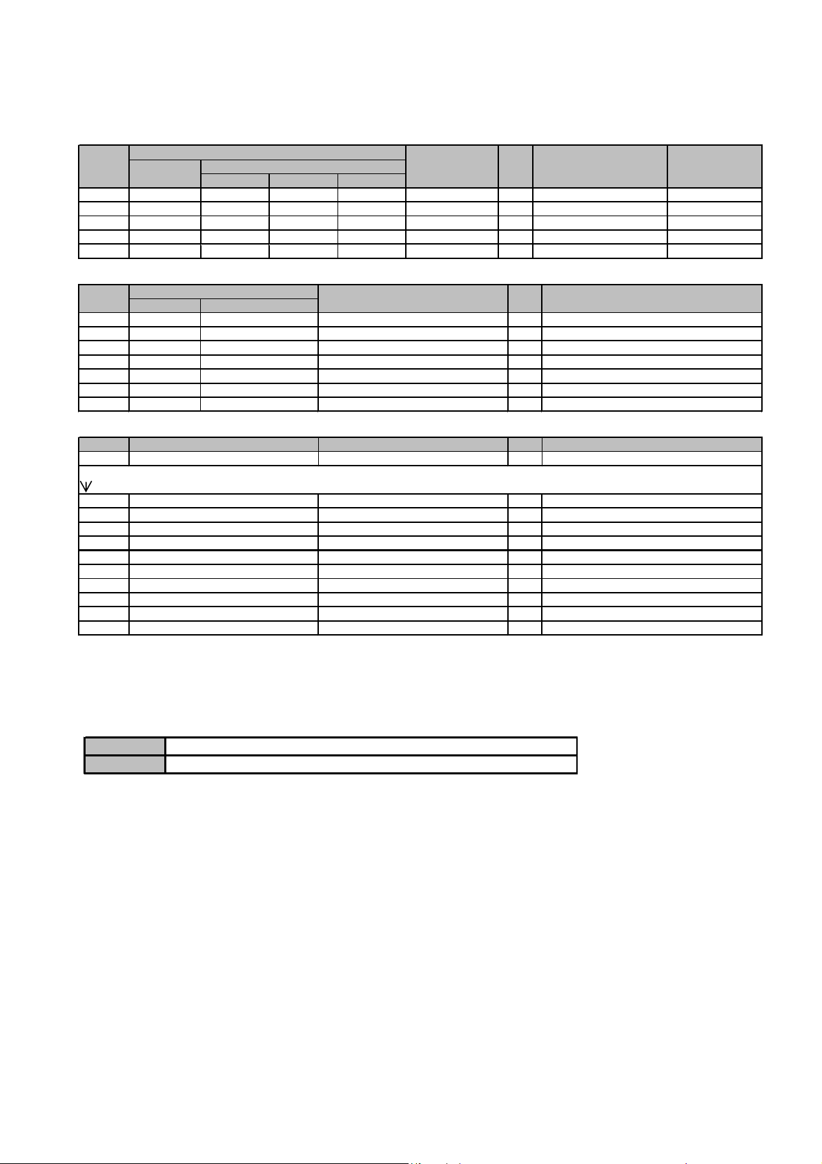
2. Component List and Standard Deliverable
- Component List
- AN-UHF-122 -
Application Note for Silicon RF Power Semiconductors
4/17
Page 5
RD04HMS2 & RD70HUF2 two-stage amplifier at 380-470MHz. (Vdd=12.5V)
* Inductor of Rolling Coil measurement condition : f=100MHz
No.
Description
P/N
Qty
Manufacturer
Remarks
Inductance
Diameter
WireΦInside
Φ
T/N of coils
L112
nH *
0.23mm1.1mm3
2303A
1
YC Corporation Co.,Ltd.
Enameled wire
L28
nH *
0.23mm1.1mm2
2302S
1
YC Corporation Co.,Ltd.
Enameled wire
L38
nH *
0.23mm1.1mm2
2302S
1
YC Corporation Co.,Ltd.
Enameled wire
L437
nH *
0.40mm1.6mm7
4007C
1
YC Corporation Co.,Ltd.
Enameled wire
L525
nH *
0.80mm2.2mm5
8005C
1
YC Corporation Co.,Ltd.
Enameled wire
No.
Description
P/N
Qty
Manufacturer
Resistance
Size
R
147ohm
1608
RPC05N470J
1
TAIYOSHA ELECTRIC CO.
R22.2
ohm
2012
RPC10T2R2J
1
TAIYOSHA ELECTRIC CO.
R3100
ohm
2012
RPC10T101J
1
TAIYOSHA ELECTRIC CO.
R4100
ohm
2012
RPC10T101J
1
TAIYOSHA ELECTRIC CO.
R
5
3900
ohm
1608
RPC05T392J
1
TAIYOSHA ELECTRIC CO.
R
6
2700
ohm
1608
RPC05T272J
1
TAIYOSHA ELECTRIC CO.
R
7
2700
ohm
1608
RPC05T272J
1
TAIYOSHA ELECTRIC CO.
No.
Description
P/N
Qty
Manufacturer
Pb
PCB
MS3A0208
1
Homebuilt
OPTION
Rc
SMA
female connector
PAF-S00-002
2
GIGALANE Corporation
Bc1Bias connector
red color
TM-605R
2
MSK Corporation
Bc2Bias connector
black color
TM-605B
2
MSK Corporation
Pe
Aluminum pedestal
-1Homebuilt
Pd
Thermal Silicon Compound
G746
-
Shin-Etsu Chemical Co.,Ltd
Cu1Copper plate 2.8 x 1.8 x 0.4t (mm)
-1Homebuilt
Conducting wire
-6Homebuilt
Screw
M3-2-Screw
M2.6-10-Screw
M2-10
-
Evaluation Board assembled with all the component
PCB (raw board)
- AN-UHF-122 -
- Standard Deliverable
TYPE1
TYPE2
Application Note for Silicon RF Power Semiconductors
5/17
Page 6
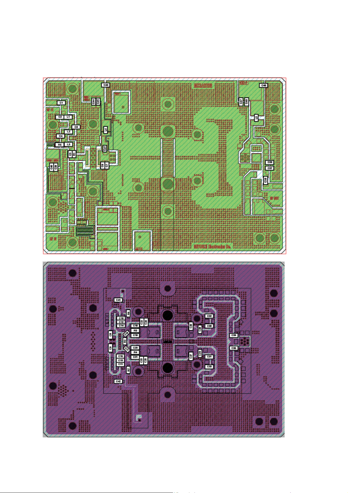
3. PCB Layout
TOP VIEW (Layer 1)
RD04HMS2 & RD70HUF2 two-stage amplifier at 380-470MHz. (Vdd=12.5V)
- AN-UHF-122 -
BOARD OUTLINE: 82.5*60.0(mm)
BOTTOM VIEW (Layer 6), Perspective through Top View
Application Note for Silicon RF Power Semiconductors
6/17
Page 7

RD04HMS2 & RD70HUF2 two-stage amplifier at 380-470MHz. (Vdd=12.5V)
Internal Layer (Layer 2) , Perspective Through Top View
Internal Layer (Layer 3) , Perspective Through Top View
- AN-UHF-122 -
BOARD OUTLINE: 82.5*60.0(mm)
Internal Layer (Layer 4) , Perspective Through Top View
Application Note for Silicon RF Power Semiconductors
7/17
Page 8

RD04HMS2 & RD70HUF2 two-stage amplifier at 380-470MHz. (Vdd=12.5V)
Nomial Total Completed Thickness ( included resist coating ) : 1.6mm
Internal Layer (Layer 5) , Perspective Through Top View
- AN-UHF-122 -
BOARD OUTLINE: 82.5*60.0(mm)
Substrate Condition
200μm
300μm
300μm
300μm
200μm
er: 4.7, TanD:0.018 @1GHz
Prepreg
Core
Prepreg
Core
Prepreg
Layer1( Copper T: 43μm with gold plating )
Layer2( Copper T: 35μm )
Layer3( Copper T: 35μm )
Layer4( Copper T: 35μm )
Layer5( Copper T: 35μm )
Layer6( Copper T: 43μm with gold plating )
Material: MCL-E-679G(R), Hitachi Chemical Co.
Application Note for Silicon RF Power Semiconductors
8/17
Page 9

RD04HMS2 & RD70HUF2 two-stage amplifier at 380-470MHz. (Vdd=12.5V)
4.7
3.4
0.8
8.0
4. Standard Land Pattern Dimensions
4-1. RD70HUF2
=
.
a
i
D
8.3
3.3
- AN-UHF-122 -
6.52.8 13.54.9 3.5
9
.
4
1.2
18.0
19.7
23.4 25.4
4-2. RD04HMS2
3.8
3.2
4.1
UNIT: mm
0.5
0.4
60°
0.4
REGULAR TRIANGLE ARRANGEMENT
2.0
UNIT: mm
Application Note for Silicon RF Power Semiconductors
THROUGH HOLE
9/17
Page 10

RD04HMS2 & RD70HUF2 two-stage amplifier at 380-470MHz. (Vdd=12.5V)
5. Typical RF Characteristics
5-1. Frequency characteristics
@ Pin Control (@Pi=0.2W, 0.1W), Vdd=12.5V, Idq=1.1A (Vgg=2.67V)
- AN-UHF-122 -
95
85
75
Po (W)
65
@Pi=0.2W
@Pi=0.1W
55
45
370 390 410 430 450 470
f (MHz)
65
@Pi=0.2W
60
55
ηT(%)
50
35
@Pi=0.1W
30
Gp (dB)
25
@Pi=0.2W
20
370 390 410 430 450 470
f (MHz)
0
-10
-20
-30
2fo (dBc)
-40
@Pi=0.2W @Pi=0.1W
45
@Pi=0.1W
40
370 390 410 430 450 470
f (MHz)
16.0
@Pi=0.2W
14.0
12.0
Idd (A)
10.0
8.0
6.0
370 390 410 430 450 470
@Pi=0.1W
f (MHz)
-50
-60
370 390 410 430 450 470
f (MHz)
0
@Pi=0.2W
-10
R.L. (dB)
-20
@Pi=0.1W
-30
370 390 410 430 450 470
f (MHz)
Application Note for Silicon RF Power Semiconductors
10/17
Page 11

RD04HMS2 & RD70HUF2 two-stage amplifier at 380-470MHz. (Vdd=12.5V)
fPoPoGpIddηT2fo
3fo
R.L.
(MHz)
(W)
(dBm)
(dB)
(A)
(%)
(dBc)
(dBc)
(dB)
380
82.2
49.2
26.1
12.3
53.5
-33
-69.1
-4.7
390
85.7
49.3
26.3
12.2
56.3
-38
-69.2
-6.1
400
86.3
49.4
26.3
12.3
56.4
-43
-69.3
-7.9
410
85.7
49.3
26.3
12.1
57.1
-46
-69.3
-10.4
420
86.5
49.4
26.3
12.5
55.6
-47
-69.1
-13.0
430
87.5
49.4
26.4
12.7
55.1
-47
-69.2
-14.7
440
88.3
49.5
26.4
13.1
54.3
-45
-69.3
-14.9
450
86.7
49.4
26.4
12.9
53.8
-41
-69.2
-13.8
460
83.0
49.2
26.2
12.4
53.8
-45
-68.4
-13.0
470
79.4
49.0
26.0
11.8
54.0
-61
-68.6
-12.9
fPoPoGpIddηT2fo
3fo
R.L.
(MHz)
(W)
(dBm)
(dB)
(A)
(%)
(dBc)
(dBc)
(dB)
380
77.4
48.9
28.9
11.8
52.5
-32
-68.8
-4.6
390
80.5
49.1
29.0
11.6
55.5
-38
-68.9
-6.4
400
81.8
49.1
29.1
11.8
55.3
-42
-69.0
-8.7
410
83.0
49.2
29.2
11.8
56.7
-45
-69.1
-12.0
420
83.0
49.2
29.2
12.1
55.0
-46
-69.1
-15.6
430
79.8
49.0
29.0
11.9
53.6
-45
-68.8
-15.8
440
74.5
48.7
28.7
11.6
51.6
-42
-68.6
-14.2
450
67.8
48.3
28.3
10.9
49.7
-38
-68.1
-13.3
460
60.4
47.8
27.8
10.1
47.8
-42
-67.2
-12.7
470
55.1
47.4
27.4
9.4
46.8
-57
-66.8
-12.8
5-1-1. Frequency characteristics data
- AN-UHF-122 -
@ Pi=0.2W, Vdd=12.5V, Idq=1.1A
@ Pi=0.1W, Vdd=12.5V, Idq=1.1A
(Vgg=2.67V, RD04HMS2 ; 0.1A, RD70HUF2 ; 1A)
(Vgg=2.67V, RD04HMS2 ; 0.1A, RD70HUF2 ; 1A)
Application Note for Silicon RF Power Semiconductors
11/17
Page 12

RD04HMS2 & RD70HUF2 two-stage amplifier at 380-470MHz. (Vdd=12.5V)
5-2. Pout vs. Pin characteristics
@ Vdd=12.5V, Idq=1.1A (Vgg=2.67V), f=380MHz, 425MHz, 470MHz
- AN-UHF-122 -
100
80
60
Po (W)
40
20
0
0.00 0.10 0.20 0.30
35
30
Gp (dB)
25
380MHz
380MHz
425MHz
470MHz
Pi (W)
425MHz
470MHz
50
425MHz
45
40
35
Po (dBm)
30
25
20
5 10 15 20 25
16
12
8
Idd (A)
4
380MHz
380MHz
470MHz
Pin (dBm)
425MHz
470MHz
20
5 10 15 20 25
Pin (dBm)
70
60
50
40
ηT (%)
30
20
10
0
5 10 15 20 25
425MHz
470MHz
380MHz
Pin (dBm)
0
5 10 15 20 25
Pin (dBm)
Application Note for Silicon RF Power Semiconductors
12/17
Page 13

RD04HMS2 & RD70HUF2 two-stage amplifier at 380-470MHz. (Vdd=12.5V)
PiPiPoPoGp
IddηT2fo
3fo
R.L.
(W)
(dBm)
(W)
(dBm)
(dB)
(A)
(%)
(dBc)
(dBc)
(dB)
0.003
5.1
3.44
35.4
30.3
2.50
10.9
-28
< -50
-5.0
0.005
7.3
5.69
37.6
30.3
3.11
14.5
-28
< -50
-4.5
0.009
9.5
9.7
39.9
30.4
3.98
19.2
-27
< -60
-4.2
0.014
11.5
16.3
42.1
30.6
5.11
25.3
-27
< -60
-4.1
0.023
13.5
27.4
44.4
30.8
6.59
33.0
-27
< -60
-4.1
0.036
15.6
45.3
46.6
31.0
8.58
42.0
-28
< -60
-4.1
0.057
17.5
65.3
48.2
30.6
10.6
49.3
-31
< -60
-4.2
0.090
19.5
76.7
48.9
29.3
11.7
52.4
-32
< -60
-4.6
0.114
20.6
78.9
49.0
28.4
11.9
53.2
-33
< -60
-4.7
0.144
21.6
80.4
49.1
27.5
12.0
53.5
-33
< -60
-4.7
0.181
22.6
81.7
49.1
26.5
12.2
53.7
-33
< -60
-4.7
0.231
23.6
83.0
49.2
25.6
12.3
53.9
-33
< -60
-4.7
0.292
24.7
84.3
49.3
24.6
12.4
54.2
-33
< -60
-4.7
PiPiPoPoGp
IddηT2fo
3fo
R.L.
(W)
(dBm)
(W)
(dBm)
(dB)
(A)
(%)
(dBc)
(dBc)
(dB)
0.003
5.0
5.81
37.6
32.7
3.01
15.3
-38
< -50
-10.2
0.005
7.2
9.3
39.7
32.5
3.73
19.7
-38
< -50
-14.0
0.009
9.3
15.1
41.8
32.4
4.70
25.4
-38
< -60
-20.2
0.014
11.4
24.2
43.8
32.5
5.92
32.3
-38
< -60
-20.4
0.022
13.4
38.0
45.8
32.4
7.49
40.3
-38
< -60
-17.0
0.035
15.4
54.3
47.4
31.9
9.19
47.0
-40
< -60
-15.8
0.056
17.4
69.8
48.4
31.0
10.8
51.7
-43
< -60
-15.8
0.090
19.6
81.1
49.1
29.5
11.9
54.3
-45
< -60
-16.8
0.114
20.6
84.1
49.3
28.7
12.3
54.9
-46
< -60
-17.1
0.142
21.5
85.9
49.3
27.8
12.4
55.2
-47
< -60
-15.7
0.177
22.5
86.9
49.4
26.9
12.5
55.4
-47
< -60
-14.6
0.224
23.5
87.5
49.4
25.9
12.6
55.5
-47
< -60
-13.6
0.280
24.5
87.9
49.4
25.0
12.6
55.6
-47
< -60
-12.9
PiPiPoPoGp
IddηT2fo
3fo
R.L.
(W)
(dBm)
(W)
(dBm)
(dB)
(A)
(%)
(dBc)
(dBc)
(dB)
0.003
4.9
1.52
31.8
26.9
1.85
6.5
-51
< -50
-10.3
0.005
7.1
2.48
33.9
26.8
2.19
8.9
-52
< -51
-15.1
0.008
9.3
4.12
36.2
26.9
2.70
12.1
-53
< -53
-25.8
0.014
11.3
6.90
38.4
27.1
3.40
16.1
-53
< -55
-16.6
0.022
13.3
11.6
40.7
27.3
4.33
21.3
-54
< -60
-14.9
0.035
15.4
19.9
43.0
27.6
5.61
28.1
-54
< -60
-14.1
0.055
17.4
32.8
45.2
27.7
7.19
36.3
-54
< -60
-13.7
0.089
19.5
51.1
47.1
27.6
9.11
44.7
-56
< -60
-13.6
0.112
20.5
60.1
47.8
27.3
10.00
48.0
-58
< -60
-12.9
0.140
21.5
68.4
48.4
26.9
10.82
50.5
-59
< -60
-12.9
0.177
22.5
75.5
48.8
26.3
11.5
52.4
-61
< -60
-12.9
0.223
23.5
81.5
49.1
25.6
12.1
53.8
-62
< -60
-12.9
0.286
24.6
86.1
49.4
24.8
12.6
54.6
-63
< -60
-13.0
5-2-2. Pout vs. Pin characteristics data
- AN-UHF-122 -
[Conditions ; Vdd=12.5V, Idq=1.1A
@ f=380MHz
@ f=425MHz
(Vgg=2.67V, RD04HMS2 ; 0.1A, RD70HUF2 ; 1A)
]
@ f=470MHz
Application Note for Silicon RF Power Semiconductors
13/17
Page 14

RD04HMS2 & RD70HUF2 two-stage amplifier at 380-470MHz. (Vdd=12.5V)
5-3. Pout vs. Vdd characteristics
@ Pi=0.2W (=23dBm), Idq=1.1A(Vgg=2.67V), f=380MHz, 425MHz, 470MHz
- AN-UHF-122 -
100
80
60
Po (W)
40
20
0
2 4 6 8 10 12 14
30
25
20
Gp (dB)
15
10
470MHz
380MHz
425MHz
Vdd (V)
380MHz
425MHz
470MHz
50
470MHz
45
40
Po (dBm)
35
30
2 4 6 8 10 12 14
16
12
470MHz
8
Idd (A)
4
425MHz
380MHz
Vdd (V)
380MHz
425MHz
5
2 4 6 8 10 12 14
Vdd (V)
70
60
ηT (%)
50
40
380MHz
425MHz
2 4 6 8 10 12 14
Vdd (V)
0
2 4 6 8 10 12 14
Vdd (V)
470MHz
Application Note for Silicon RF Power Semiconductors
14/17
Page 15

RD04HMS2 & RD70HUF2 two-stage amplifier at 380-470MHz. (Vdd=12.5V)
VddPoPoGpIddηT(V)
(W)
(dBm)
(dB)
(A)
(%)
2.0
1.4
31.5
8.5
1.73
41.3
3.0
3.9
36.0
12.9
2.72
48.3
3.6
6.1
37.8
14.8
3.33
50.6
5.0
13.0
41.1
18.1
4.85
53.5
6.0
19.7
43.0
19.9
5.98
54.9
7.2
29.2
44.7
21.6
7.32
55.6
8.0
36.6
45.6
22.6
8.22
55.6
9.5
51.2
47.1
24.1
9.7
55.4
11.0
66.8
48.3
25.2
11.0
55.0
12.5
84.1
49.3
26.2
12.3
54.5
13.6
97.3
49.9
26.9
13.3
54.0
VddPoPoGpIddηT(V)
(W)
(dBm)
(dB)
(A)
(%)
2.0
1.5
31.8
8.8
1.91
39.6
3.0
3.9
35.9
12.9
2.86
45.5
3.6
6.0
37.8
14.7
3.47
48.0
5.0
12.6
41.0
18.0
4.90
51.5
6.0
18.9
42.8
19.7
5.94
52.9
7.2
28.1
44.5
21.5
7.18
54.3
8.0
35.2
45.5
22.4
8.01
54.9
9.5
50.6
47.0
24.0
9.56
55.6
11.0
68.2
48.3
25.3
11.1
55.9
12.5
87.9
49.4
26.4
12.5
56.1
13.6
103.3
50.1
27.1
13.6
55.8
VddPoPoGpIddηT(V)
(W)
(dBm)
(dB)
(A)
(%)
2.0
2.3
33.6
10.6
2.41
47.9
3.0
5.5
37.4
14.4
3.52
52.4
3.6
8.1
39.1
16.0
4.17
53.6
5.0
15.7
42.0
18.9
5.66
55.2
6.0
22.3
43.5
20.5
6.69
55.7
7.2
31.8
45.0
22.0
7.87
56.0
8.0
38.6
45.9
22.8
8.59
56.2
9.5
52.1
47.2
24.1
9.82
55.8
11.0
65.8
48.2
25.2
10.92
54.9
12.5
79.3
49.0
26.0
11.9
53.4
13.6
87.9
49.4
26.4
12.4
52.1
5-3-1. Pout vs. Vdd characteristics data
- AN-UHF-122 -
[Conditions ; Pi=0.2W (=23dBm), Idq=1.1A
@ f=380MHz
@ f=425MHz
(Vgg=2.67V, RD04HMS2 ; 0.1A, RD70HUF2 ; 1A)
]
@ f=470MHz
Application Note for Silicon RF Power Semiconductors
15/17
Page 16

RD04HMS2 & RD70HUF2 two-stage amplifier at 380-470MHz. (Vdd=12.5V)
5-4. Pout vs. Vgg characteristics
@ Vdd=12.5V, Pi=0.2W (=23dBm), f=380MHz, 425MHz, 470MHz
- AN-UHF-122 -
110
90
425MHz
70
Po (W)
50
30
10
1.5 2.0 2.5 3.0
28
425MHz
26
24
22
Gp (dB)
20
18
380MHz
470MHz
Vgg (V)
380MHz
470MHz
50
45
Po (dBm)
40
16
12
Idd (A)
425MHz
380MHz
470MHz
1.5 2.0 2.5 3.0
Vgg (V)
380MHz
425MHz
8
4
470MHz
16
1.5 2.0 2.5 3.0
Vgg (V)
70
60
50
40
30
ηT (%)
20
10
425MHz
380MHz
470MHz
0
1.5 2.0 2.5 3.0
Vgg (V)
0
1.5 2.0 2.5 3.0
Vgg (V)
4
3
2
Idq(A)
1
0
1.5 2.0 2.5 3.0
Vgg (V)
Application Note for Silicon RF Power Semiconductors
16/17
Page 17

RD04HMS2 & RD70HUF2 two-stage amplifier at 380-470MHz. (Vdd=12.5V)
Vgg
IdqPiPiPoPoGpIddηT(V)
(A)
(W)
(dBm)
(W)
(dBm)
(dB)
(A)
(%)
1.5000.200
23.0
20.3
43.1
20.1
5.00
32.2
2.00
0.001
0.200
23.0
47.8
46.8
23.8
8.38
45.4
2.10
0.004
0.200
23.0
53.1
47.3
24.2
9.0
47.2
2.20
0.012
0.200
23.0
58.5
47.7
24.7
9.5
48.9
2.30
0.04
0.201
23.0
63.8
48.1
25.0
10.1
50.3
2.40
0.11
0.200
23.0
69.2
48.4
25.4
10.7
51.6
2.50
0.28
0.200
23.0
74.5
48.7
25.7
11.3
52.9
2.60
0.62
0.200
23.0
79.6
49.0
26.0
11.8
54.0
2.65
0.90
0.200
23.0
82.2
49.2
26.1
12.1
54.5
2.70
1.20
0.200
23.0
84.7
49.3
26.3
12.3
55.0
2.75
1.63
0.200
23.0
87.1
49.4
26.4
12.6
55.4
2.80
2.07
0.200
23.0
89.3
49.5
26.5
12.8
55.8
2.85
2.64
0.200
23.0
91.6
49.6
26.6
13.1
56.1
2.90
3.22
0.201
23.0
93.8
49.7
26.7
13.32
56.4
Vgg
IdqPiPiPoPoGpIddηT(V)
(A)
(W)
(dBm)
(W)
(dBm)
(dB)
(A)
(%)
1.5000.201
23.0
40.7
46.1
23.1
7.16
45.2
2.00
0.001
0.201
23.0
68.7
48.4
25.3
10.25
53.5
2.10
0.004
0.201
23.0
72.3
48.6
25.6
10.6
54.2
2.20
0.012
0.200
23.0
75.5
48.8
25.8
11.0
54.8
2.30
0.04
0.200
23.0
78.5
49.0
25.9
11.4
55.3
2.40
0.11
0.200
23.0
81.5
49.1
26.1
11.7
55.7
2.50
0.28
0.201
23.0
84.1
49.3
26.2
12.0
56.1
2.60
0.62
0.201
23.0
86.7
49.4
26.4
12.3
56.3
2.65
0.90
0.200
23.0
88.1
49.5
26.4
12.5
56.4
2.70
1.20
0.201
23.0
89.3
49.5
26.5
12.7
56.5
2.75
1.63
0.201
23.0
90.8
49.6
26.6
12.8
56.6
2.80
2.07
0.201
23.0
91.8
49.6
26.6
13.0
56.6
2.85
2.64
0.201
23.0
93.3
49.7
26.7
13.2
56.8
2.90
3.22
0.200
23.0
94.4
49.8
26.7
13.32
56.8
Vgg
IdqPiPiPoPoGpIddηT(V)
(A)
(W)
(dBm)
(W)
(dBm)
(dB)
(A)
(%)
1.5000.201
23.0
6.3
38.0
15.0
2.97
16.8
2.00
0.001
0.201
23.0
37.2
45.7
22.7
7.15
41.3
2.10
0.004
0.201
23.0
44.9
46.5
23.5
8.0
44.8
2.20
0.012
0.200
23.0
52.5
47.2
24.2
8.8
47.7
2.30
0.04
0.201
23.0
59.6
47.8
24.7
9.5
50.0
2.40
0.11
0.201
23.0
66.2
48.2
25.2
10.2
51.8
2.50
0.28
0.201
23.0
72.1
48.6
25.5
10.8
53.1
2.60
0.62
0.201
23.0
77.4
48.9
25.9
11.4
54.2
2.65
0.90
0.201
23.0
79.6
49.0
26.0
11.7
54.5
2.70
1.20
0.201
23.0
81.8
49.1
26.1
11.9
54.9
2.75
1.63
0.201
23.0
84.1
49.3
26.2
12.2
55.2
2.80
2.07
0.201
23.0
86.1
49.4
26.3
12.4
55.5
2.85
2.64
0.201
23.0
88.1
49.5
26.4
12.6
55.8
2.90
3.22
0.201
23.0
89.7
49.5
26.5
12.85
56.0
5-4-1. Pout vs. Vgg characteristics data
[Conditions ; Pi=0.2W (=23dBm), Vdd=12.5V
@ f=380MHz
- AN-UHF-122 -
@ f=425MHz
@ f=470MHz
Application Note for Silicon RF Power Semiconductors
17/17
 Loading...