

Page 1
MlTSUBlSHl
Mitsubishi
General Use
PC
User’s
Manual
Model
A1
S64TCTT, TCTI, TCRT, and TCRl
Temperature Control Module
Model
AI
S64BW Heater Disconnection
Detection Module
(Hardware)
Thank you for buying the Mltsubishl General Use PC MELSEC-A Series
Before use, piease read thls manual carefully and correctly operate the module wlth a
sufllcient understanding of the
A
series PC functions and pedormance.
Please dace this manual In a locatlon where
It
IS
available
to
end users.
MITSUBlSHl
ELECTRC
I6
(NA)-66662-A(9604)
MEE
Page 2
0
SAFETY
PRECAUTIONS
0
(Please read
these
precautions before using.)
When using this Model, thoroughly read this manual and
the associated manuals introduced in this manual.
Also
pay
careful attention to safety and handle the module properly.
These precautions apply only to this Model. Refer to the
CPU module user’s manual for a description of the PC system safety precautions.
These
SAFETY PRECAUTIONS classify the safety pre-
cautions into two categories:“DANGER” and “CAUTION”.
/-----------------
IT-.
\
,
Procedures which may lead to a dangerous condition and cause death or serious
injury if not carried out properly.
,
CAVT,ON
Procedures which may lead to a danger-
I
=
ous condition and cause superficial to me-
I
I
I
I
I I
I
dium injury, or physical damage only, if not
I
I
carried out properly.
I
Depending on circumstances, procedures indicated by
CAUTION may also be linked to serious results.
Store this manual in a safe place
so
that you can take
it
out
and read
it
whenever necessary. Always forward it to the
end user.
Page 3
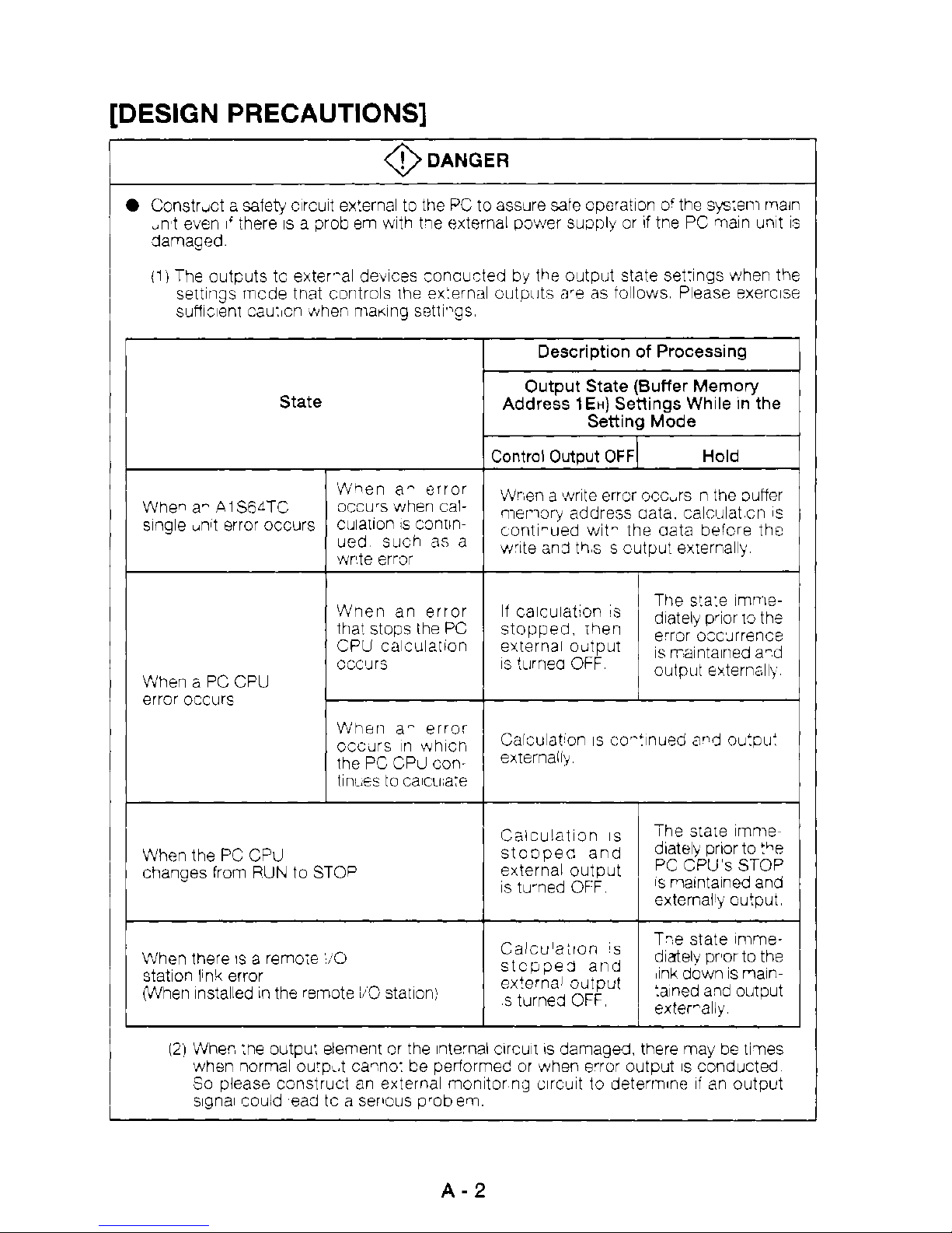
[DESIGN
PRECAUTIONS]
r
0
DANGER
0
Constrd a saieb, clrcult ex!ernal
to
the
PC to assure
Sale
opmtlon o'the srj:8111 main
,n't even there
IS
a prob em with tle external pwer suqjly or
If
tne PC maln unlt
IS
clamaged
ill
The oLltputs
tc
exteval
devices
concu-ted by the olJtput state set'lngs when the
sufhent cauxn $#tier, mamg settl-gs
settlngs rncde
trlat
coritrols Ihe ex:ernal
cutwts
ape as
iollows
Please exerclse
State
i"hen
a-
error
ued swh as a
'h'nen an error
ttla! stops the
PC
CPU
calxlation
ccc?Irs
When 6 PC CPU
error occm
Wherl a- error
cccdrs
111
whlcn
the PC CPcl contlnL.es
tc
ca1cua:e
When the
PC
CPU
changes from
PUN
to
STOP
When there
IS
a
remoie
,O
pflhen Installed
In
the remote
ib0
statlon:
statlon IPnk error
Descriptlon
of
Processlng
1
Address
1En)
Senings While In the
Output State (Suffer
Memory
Setting Mode
'rWeri a wrlte errcr occurs n
the
3uffer
qier.iory address uata. calcl.llat
cn
1s
contl-ued
wlt-
the aata befcre the
wie
an3
ths
s
cutput exwnally
Caicuiatlon
IS
StoDpec and
external output
IS
tu-ned
OFF
Ca1cuIa:lon
's
stcppe3 and
external outpu!
s
turnecl
OFF
The srare
llnnle
dlately
prlor
to
the
1s
maintalned and
PC
CPU's
STOP
T-e state lmmedlaielv pr'or
to
the
:alned ald output
,Ink down
1s
nalm
externally
121
Whec :he outpu: element or the lnte'nal clrcull
IS
damaged there ma) be
tines
when normal ou'p'..t camo:
be
periormed or when e'ror output
IS
conducted
So
please construct
an
external monltor ng clrc8A
to
deterrnm
li
an
output
Slqnal could
ead
tc a semus o'ob
em
A-2
Page 4
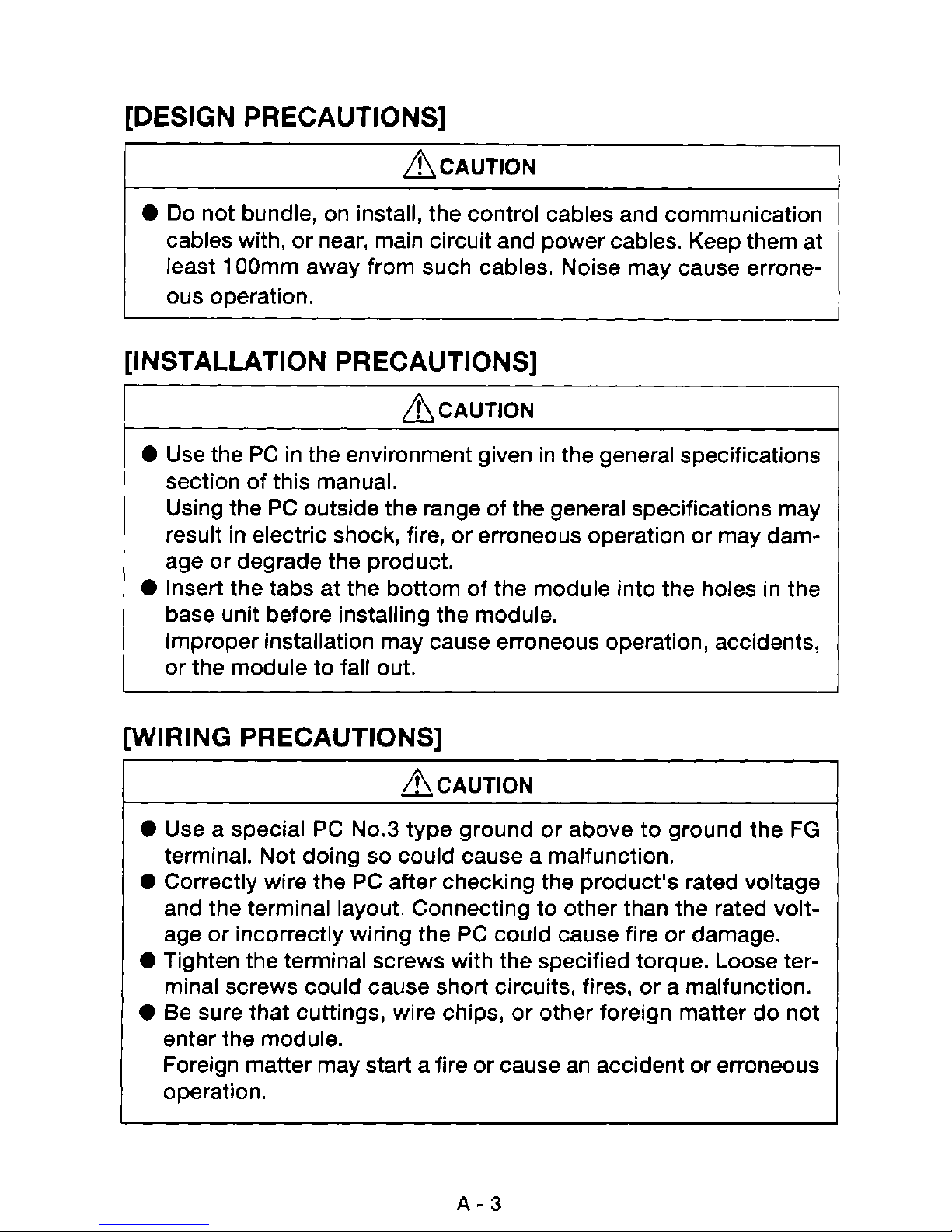
[DESIGN PRECAUTIONS]
ACAUTION
0
Do
not bundle, on install, the control cables and communication
cables with, or near, main circuit and power cables. Keep them at
1
least
ous
OOmm away from such cables. Noise may cause errone-
operation.
[INSTALLATION PRECAUTIONS]
ACAUTION
0
Use the PC in the environment given in the general specifications
section of this manual.
Using the PC outside the range of the general specifications may
result in electric shock, fire, or erroneous operation or may damage or degrade the product.
0
Insert the tabs at the bottom of the module into the holes in the
base unit before installing the module.
Improper installation may cause erroneous operation, accidents,
or the module to fall out.
[WIRING PRECAUTIONS]
ACAUTION
0
Use a special PC N0.3 type ground or above to ground the FG
so
terminal. Not doing
0
Correctly wire the PC after checking the product's rated voltage
and the terminal layout. Connecting to other than the rated voltage or incorrectly wiring the PC could cause fire or damage.
0
Tighten the terminal screws with the specified torque. Loose terminal screws could cause short circuits, fires, or a malfunction.
0
Be sure that cuttings, wire chips, or other foreign matter do not
enter the module.
Foreign matter may start a fire or cause an accident or erroneous
could cause a malfunction.
i
operation.
A-3
Page 5
[STARTING AND MAINTENANCE PRECAUTIONS]
ACAUTION
0
Do not touch live terminals.
It may cause erroneous operation.
0
Turn
OFF
the power before cleaning the module or retightening
the screws. Doing this work while the power is on may damage
the module or cause erroneous operation.
ACAUTION
I
0
Do
not disassemble or rebuild the module.
It may cause accidents, erroneous operation, injury, or fire.
0
Turn
OFF
the power before mounting and dismounting the mod-
ule.
Mounting or dismounting the module while the power is
on
may
damage the module or cause erroneous operation.
[DISPOSAL PRECAUTIONS]
ACAUTION
0
When disposing of this product, handle it as industrial waste.
A-4
Page 6
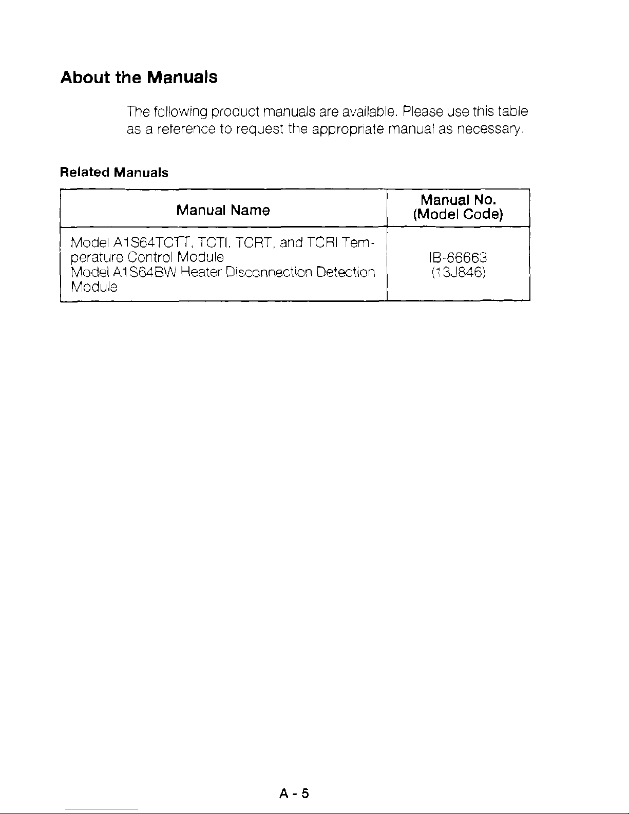
About the Manuals
The following product manuals are
to
as a reference
Related Manuals
I
Model AlS64TCn, TCTI. TCRT, and TCRI Temperature Control Module
Model
Module
AlS64BW
Manual Name
Heater Dlsconnectlon Detection
request the approprlate manual as necessary
available.
Please use
Manual
I
(Model Code)
.-
18-66663
(1
this
No.
~-,
3J846)
table
1
Page 7
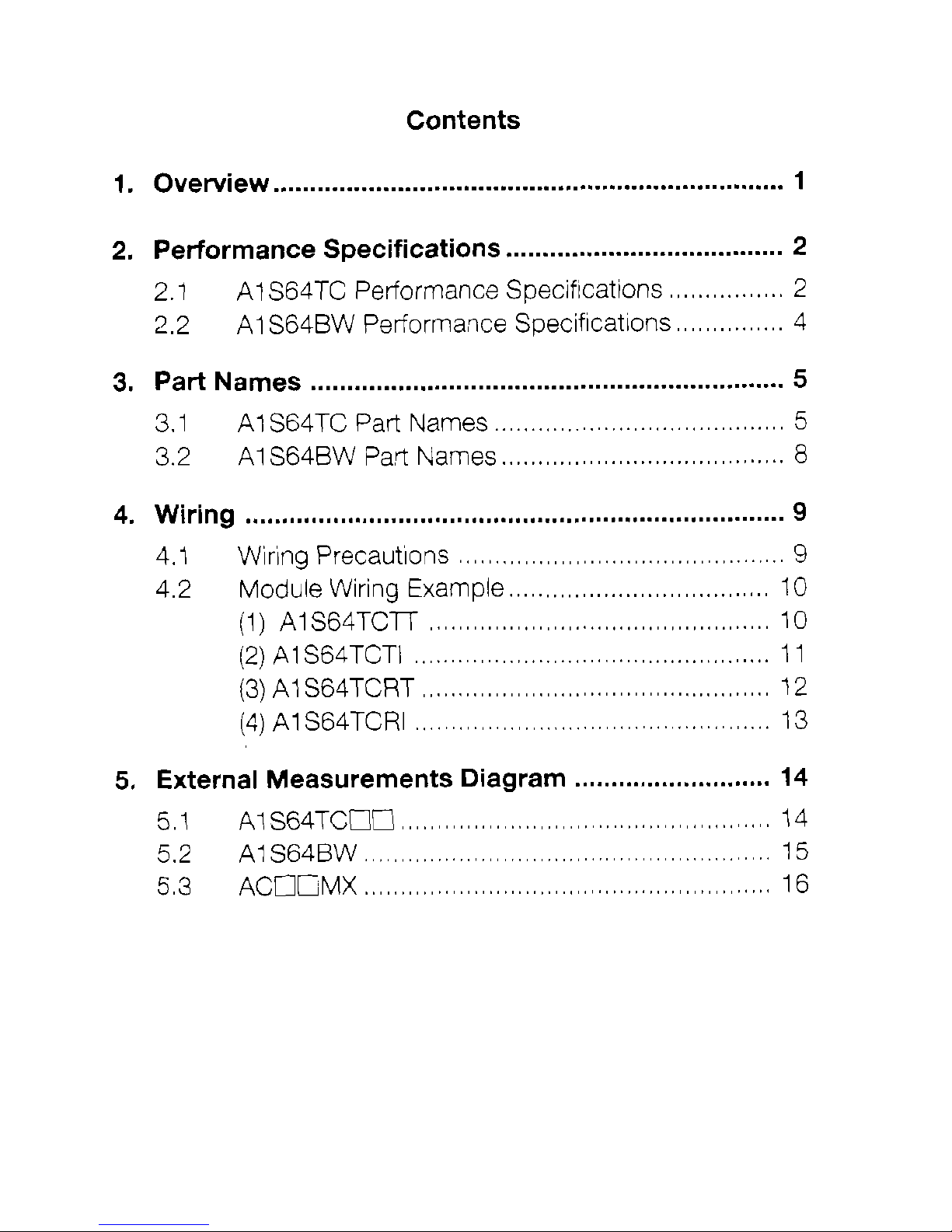
Contents
1 . Overview
2
.
Performance Specifications
2.1 AI S64TC Performance Speciflcattons
2.2
3
.
Part Names
3.1 AlS64TC Part Names
3.2
4 . Wiring
4.1 Wiring Precautlons
4.2
......................................................................
......................................
A1 S64BW Performance Speciflcatlons
.................................................................
........................................
AI S64BW Part Names
.......................................
..........................................................................
.............................................
Module Wiring Example
(1)
AlS64TClT
...............................................
....................................
1
2
................
...............
2
4
5
5
8
9
9
10
10
(2)
AlS64TCTI
(3)
AlS64TCRT
(4) AlS64TCRI
5
.
External Measurements Diagram
5.1
5.2
5.3
At S64TCUG
A1 S64BW
ACOCMX
........................................................
........................................................
.................................................
................................................
.................................................
...................................................
...........................
11
12
13
14
14
15
16
Page 8

1
Overview
This manual explains the speciflcatlons. names
ing. for the following modules that are combined wlth the MELSEC-
A
serles AnSCPU module (hereafter abbrevlated PC CPti).
Model
abbreviated AIS64TCm
Model AlS64TCTI Temperature Con!rol Module [hereater
abbrevlated AlS64TCTII
Model AIS64TCRTTenlperar~e Con!rol Module (hereafter
abbrevla!ed
Model AlS64TCRl Terrpers!ure Control Moaule (hereaiter
aboreblated 41 S64TCRIj
Model AIS64BW Heater Dlscorinectlon
inereafler abbrevlated
The
by convertlng the external temperature sensor (thermocoupleheslstance thermometer bulb) Input values
data dlgltal value and then externally outputs thls data
AI
S64TC
AI
S64TCTT Tempe,ature Control Module (hereafter
AlSB4TCRTI
Detection
A’S64BW
is
a speclal module that controls the temperature
to a 16
of
Mod,le
parts, and w~r-
Hereater all
A1 S64TC
1
bit coded BIN
to
the transistor outputlcurrent output that automatlcally conducts PID calculation.
In addltion,
another ND
memory by the sequence program as a temperature measurement value, external output
current output that automatlcally conducts
can be used for a wide varlety of process controls.
The
A:
S64BW
power
translstor
Following
input types, and control output types.
to
Model
A1 S64TCTr Trnnslstor Cutpur
If
BIN data handled by the PC CPti. such as from
conversion
is
a
specla1
a
unlt
being controlled
output
IS
type temperature control module (AlS64TCllflCRV.
shown the temperature control module, temperature
1
Temperature
module,
IS
posslble from the transistor outputi
unlt
that can detect dlsconnectlon
oy
Input
Thernocouole
IS
written
belng used
Types
[
to
thls
module’s buffer
PID
calculation,
In
combmation
Control Output
of
the input
so
wlth
Types
it
a
Page 9

Page 10

Page 11

Page 12

Page 13

Page 14

Page 15

3.2
AlS64BW
Part
0
\
Names
1No.l
0
3
Name
Term'nal Glock
Connector
0
\
I
Re'er
to
lteni 3 2
Connector fcr connecilng the
-0
make the
heater
ACOlMX
d
sconnectlon oelectlon
IS
Descriotion
connection,
packaged wltti theA'S6IBLV
#use
AlSWTCTbTCRT
lnodel
ACT
mt
connection
MX or
catie
ACI
I
2MX
Ithe
Page 16

4
Wiring
This sectlon explalns the wirlng precautlons usmg an example
module connection.
4.1
Wiring Precautions
Sufficiently
shows that one
tem
IS
Followlng are glven precautlons for external wlrlng.
(1)
Use separate cables for the alternatlng current control clrcult
and the
that there
Inductance.
(2)
Do
age wes.
Be
eter bulbs 1 OOrnm or farther from maln clrcult wlres and alternatlng current control clrcults.
understandlng the
external wlrlng that
A1
IS
not
place near
or
sure
to
place the thermal couple and reslstance thermom-
AI
S64TC and
of
the condltlons
IS
S64TC and
no
effect from the alternatlng current surge
or
load wlres from other than the PC.
AI
bundle wlth maln clrcult wires, hlgh volt-
for
bulldmg a highly fellable
not easlly affected by nolse.
S64BW external inpot signals
A1
S64BW
functlons
sys-
so
or
Place sufflclently far from clrcults that Include high frequencles
scicn
Not
nom surges, and Inductance.
13)
Use one polnt groundlng on the PC slde for the
shlelded wlres
condrtions rmay make
done on the external slde.
as
high
dolng
voltage wires and Inverted load maln
so
makes
and
IS
easy for the wlres
shlelded cables.
It
more favorable for the ground
However,
to
circuits.
be affected by
shielding
external nose
to
of
be
Page 17

4.2
Module
(1)
AlS64TCTT
Wiring
Example
A1
S64TCTT
’:
For
the cable
use
a compensating conductor
10
Connection Cable
(ACOlMXIAC12MX)
wlth
shleldlng.
Page 18

[2)
AI
S64TCTI
AI
S64TCTl
*:
For
the cable use a
compensating
conductor
wlth
shleldlng
Page 19

(3)
A1
S64TCRT
AlS64TCRT
+:
For
the
cabie
use a cornpensatlng
12
(ACOlMX/ACl2MX)
conductor
wlth
shielding
Page 20

(4)
AI
S64TCRI
..
For
the cable
use a compensatlng conductor with shieldmg.
Page 21

5
External Measurements Diagram
5.1
A1
S64TCCC
I
I
1345
(1.38)
I
I
I
14
Page 22

5.2
AlS64BW
a
(0.26)
ll
1
34.5
(1.38)
1
Page 23

5.3
ACCI”
Model Name
Change Dimensions
A
I
ACOIMX
I
143
t 5 15.60
i
0
21
I
16
 Loading...