

Page 1

Positioning Control
Training Manual
Page 2

Positioning Control
Cautions on Safety
Make sure to read the manuals and pay careful attention to safety when designi ng a system.
In practice, pay attention to the following contents and handle any products or dem onstration
units correctly.
Cautions on practice
DANGER
• Never touch any terminal while the power is supplied. If you touch a terminal,
you may get an electrical shock.
• Turn off the power before connecting / disconnecting units, or opening any
safety covers.
• Never insert your hand or any other object into a moving part.
CAUTION
• Never change the wiring or configuration of demonstration euipment without
permission or if you are unsure of how to configure a system correctly. Such
actions may cause failure, malfuncti on, injury or fire.
• If a simulation unit (such as an X-Y table) generates an abnormal smell or
sound, immediately turn off the power switch.
• If you detect any abnormality, immediately turn off the power and contact a
qualified engineer.
Page 3

Positioning Control
Positioning Control
Manual number: JY992D89901
Manual revision: A
Date : July 2000
i
Page 4

Positioning Control
ii
Page 5

Positioning Control
FAX BACK
Mitsubishi has a world wid e reputat ion for i ts ef forts i n continual ly developi ng and pushing ba ck
the frontiers of industrial automation. What is sometimes overlooked by the user is the care
and attention to detail that is taken with the documentation. However,to continue this process
of improvement, the comments of the Mitsubishi users are always welcomed. This page has
been designed for you,the reader,to fi ll in your comment s and fax them back t o us. W e look for ward to hearing from you.
Fax numbers: Your name....................................................
Mitsubishi Electric.... .....................................................................
America (01) 847-478-2253 Your company..............................................
Australia (02) 638-7072 .....................................................................
Germany (0 21 02) 4 86-1 12 Your location: ...............................................
South Africa (0 27) 11 444-0223 .....................................................................
United Kingdom (01707) 278-695
Please tick the box of your choice
What condition did the manual arrive in?
Will you be using a folder to store the manual?
What do you think to the manual presentation?
Are the explanations understandable?
Which explanation was most difficult to understand:................. ........................ .........................
....................................................................................................................................................
Are there any diagrams which are not clear?
If so,which:..................................................................................................................................
What do you think to the manual layout?
If there one thing you would like to see improved,what is it?.................................... ..................
....................................................................................................................................................
....................................................................................................................................................
Could you find the information you required easily using the index and/or the contents,if possi-
ble please identify your experience: ...........................................................................................
....................................................................................................................................................
....................................................................................................................................................
....................................................................................................................................................
....................................................................................................................................................
Good Minor damage Unusable
Yes No
Tidy Un-friendly
Yes Not too bad Unusable
Yes No
Good Not too bad Un-helpful
Do you have any comments in general about the Mitsubishi manuals?.....................................
....................................................................................................................................................
....................................................................................................................................................
....................................................................................................................................................
....................................................................................................................................................
Thank you for taking t he time to fill out this questionnaire. We hope you found both t he
and this manual easy to use.
product
iii
Page 6

Positioning Control
iv
Page 7

Positioning Control
Introduction
This manual describes basic oper ation for those who learn positioni ng control for the first ti me,
the aim being so that they can get training using demonstration units of Mitsubishi FA
equipment.
The following relevant manuals are available and should be referred to
FX-10GM/FX(E)-20GM Hardware and Programming manual JY992D60401
FX-10GM Users Guide JY992D68401
2N
-10GM/FX2N-20GM Hardware and Programming manual JY992D77801
FX
FX2N-10GM Users Guide JY992D77701
FX2N-20GM Users Guide JY992D77601
FX-PCS-VPS Win-E Software Manu al JY992D86801
2N
-10GM/FX2N-20GM Connection Manual JY992D81601
FX
Manual Name Number
v
Page 8

Positioning Control
vi
Page 9

Positioning Control Contents
1. The World of Positioning Control...........................................................1-1
1.1 Welcome to the new world! .................................................................................1-1
1.2 Divers ifi e d a c tu a tors..................... .. .. ........................... .. .. ........................... .. .. .....1-2
1.3 Positioning method type......................................................................................1-4
2. Positioning by AC Servo System...........................................................2-1
2.1 When an AC servo system is introduced........................ ........................ .............2-1
2.2 Examples of AC servo systems....................... .. ........................ .. ........................2-3
3. Components of Positioning Control and Their Roles ............................3-1
3.1 Positioning controller ...........................................................................................3-4
3.1.1 Command pulse and feed quantity............................................................................3-4
3.1.2 Command pulse and feed speed ..............................................................................3-4
3.1.3 Setting the acceleration/deceleration time ................................................................3-5
3.1.4 Backlash correction function ........... ...... ....... ...... ...... .................................................3-5
3.1.5 Zero point return function ..........................................................................................3-6
3.2 Servo amplifier and servo motor.......................... ................................................3-7
3.2.1 Positioning control in accordance with command pulse............................................3-7
3.2.2 Deviation counter function.........................................................................................3-7
3.2.3 Servo lock function....................................................................................................3-7
3.2.4 Regenerative brake function .....................................................................................3-8
3.2.5 Dynamic brake function...................................... ...... ....... ...... ....... .............................3-8
3.3 Drive mechanism......................................................................... ....................... .3-9
3.3.1 Concept of drive system movement quantity ............................................................3-9
3.3.2 Setting the target position........................................................................................3-11
4. Advanced Positioning............................................................................4-1
4.1 Interpolation control.............................................................................................4-1
4.2 Other con t ro ls ................................. .. ... .......................... .. .. ........................... .. .. ... 4 -3
5. Actual Positioning..................................................................................5-1
5.1 Demons tr a ti o n E q u ip me n t ..................... .. .. ........................... .. .. ...........................5-1
5.1.1 Basic Set ...................................................................................................................5-1
5.1.2 Comprehensive Set...................................................................................................5-1
5.2 Operation of the demonstration equipment .........................................................5-2
5.2.1 Program example......................................................................................................5-3
5.2.2 Writing the program...................................................................................................5-4
5.2.3 Parameters................................................................................................................5-5
5.2.4 Operation...................................................................................................................5-7
6. Product Line up .....................................................................................6-1
6.1 Position controller ................................................................................................6-1
6.2 Servo am p lif ie r... ........................... .. .. ........................... .. .. ........................... .. .. .....6-5
6.3 Servo moto r ..................... .. .. ........................... .. .. ........................... .. .. ..................6-7
Appendix A:.............................................................................................. A-1
A-1: Tentative Selection of Motor Capacity................................. ........................ .. ......A-1
A-1-1: Motor effective torque...................... ...... ....... ...... ...... ....... ...... ....... .............................A-2
A-1-2: Load inertia moment..................................................................................................A-4
vii
Page 10

Positioning Control Contents
viii
Page 11

Positioning Control The World of Positioning Control 1
1 The World of Positioning Control
2 Positioning by AC Servo Sys tem
3 Components of Positioning Control and Their Roles
4 Advanced Positioning
5 Actual Positioning
6 Product Line up
A Appendix A: Tentative Selection of Motor Capacity
Page 12

Page 13

Positioning Control
1. The World of Positioning Control
1.1 Welcome to the new world!
The positioning controller, together with the programmable controller, personal computer and
operator interface, is one of the four main units of FA (facto ry automation).
Among them, the positioning controller is important as the basis of FA, and regarded as the
center of the mechatronics field in which many senior engineers have been playing active
parts.
Positioning is all about motion, and motion often involves speed and precision. As speed can
be related to productivity, it is an area of much development. But, when the machine speed
increases, a problem with the stop precision is often generated. In order to solve this problem,
diversified grades of position controllers have been required and developed.
Improvement of the machine efficiency generates immeasurable added value, including
reduction of labour and the machine floor area for the same quantity of production.
The World of Positioning Control 1
If there are no problems related to the pos itioning aspe ct of a ma chine, it may mean that the
machine is not running most efficiently. Here is where the science of developing an optimum
positioning control system comes in.
1-1
Page 14
Positioning Control The World of Positioning Control 1
1.2 Diversified actuators
• A power source which moves an element in a system is called actuator. A unit which detects
a position of a work piece or moving part is called sensor.
• Diversified actuators and sensors, from simple ones to enhanced ones, are used in
positioning.
• This paragraph describes representat ive types, their features and weak points.
Pneumatic
• Air source and high grade piping are
required.
• High torque is not available.
• Multi-point positioning is complex and
very difficult to achieve.
• Change in pos it ion ing is difficul t.
Brake motor
• Positioning mechanism is simple.
• Repeatability is poor.
• Change in pos it ion ing is difficul t.
(When optical sensors or limit switches are
used for stop)
Clutch brake
• Frequent positioning is available.
• Life of friction plate is limited.
• Change in pos it ion ing is difficult.
(When optical sensors or limit switches are
used for stop)
1-2
Page 15
Positioning Control The World of Positioning Control 1
Stepping motor
• Positioning mechanism is simple.
• If load is heavy, motor may step out and
displacement can occur.
• Motor capacity is small.
• Precision is poor at high speed.
DC servo system
• Positioning precision is good.
• Maintenance is required for motor
brushes.
• It is not suitable for rotation at high
speed.
General purpose inverter and general
purpose motor
• Multi-speed positioning is available
using high-speed counter.
• High precision positioning is not
available.
• Large torque is not available at start.
(Specialized inverter is required)
AC servo system
• Precision is good.
• Maintenance is not required.
• Positioning address can be easily
changed.
• It is compact, and offers high power.
1-3
Page 16
Positioning Control The World of Positioning Control 1
1.3 Positioning method type
1) There are three types of positioning method
Control method Description Schematic drawing
Two limit switches are
Moving part
Ball screw
Limit switch for
changeover to
low speed
Limit switch
for stop
High speed
Low speed
Movement
distance
Speed
control
Limit
switch
method
provided in places where a
systems moving part
passes. At the first limit
switch, the motor speed is
reduced. At the second limit
switch, the motor turns off
and the brake turns on, to
stop the moving part.
In this method, because
position controllers are not
required, the system
configuration can be realized
at reasonable cost.
(Guideline of stopping
precision: Approximately
±1.0 to 5.0 mm)*
B IM
INV
DC0 to 10V
IM: Inductive motor
B: Brake
INV: Inverter
Position
control
Pulse
count
method
Pulse
command
method
A position detector (such as
pulse encoder) is set up in a
motor or rotation axis. The
pulse number generated
from the position detector is
counted by a high-speed
counter. When the pulse
number reaches the preset
value, the moving part stops.
In this method, because limit
switches are not used, the
stop position can be easily
changed.
An AC servo motor which
rotates in proportion to the
input pulse number is used
as the drive motor.
When the pulse number
corresponding to the
movement distance is input
to the servo amplifier of the
AC servo motor, positioning
can be performed at high
speed in proportion to the
pulse frequency.
Pulses are
fed back.
PLG
IM
INV
DC0 to
PC
High-speed
counter unit
Pulses are
fed back.
PLG SM
Servo
amplifier
Command
pulse
PC
Position controller
Moving part
IM: Inductive motor
PLG: Pulse generator
INV: Inverter
PLC: Programmable cont rol l er
10V
High speed
Movement distanc e
Moving part
SM: Servo motor
PLG: P ul s e generator
PLC: Programmable
Movement distance
Ball screw
Low speed
Ball screw
controller
*1 The stop precision shows a value in a case where low speed is 10 to 100 mm/s.
1-4
Page 17
Positioning Control The World of Positioning Control 1
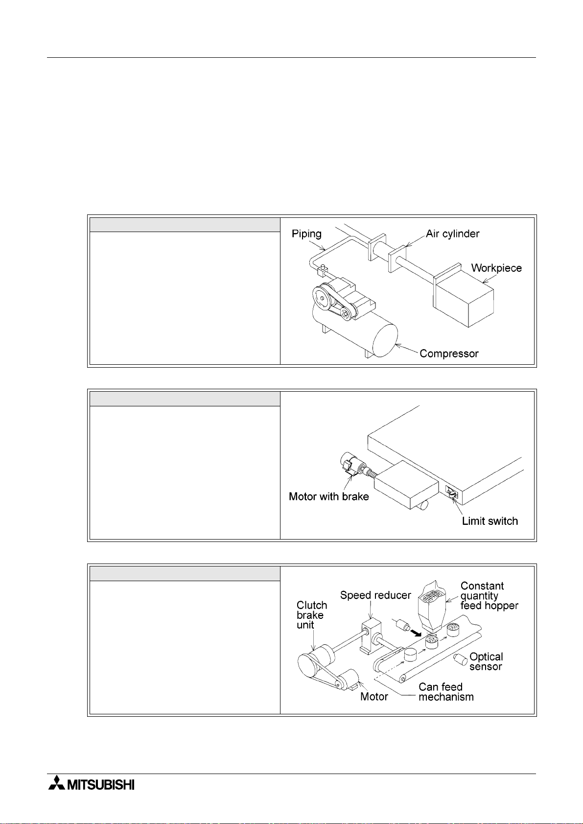
2) Positioning method and stop precision
Velocity
Stop command
Velocity
Heavy
load
Small
inertia
Stop command
Coasting
distance
Speed reduction start
Time delay
Light load
Large inertia
Dispersion
in s to p
Stop
Time
Stop
Stop
< Limit switch method >
- When automatically stopping a moving
part driven by a motor, stop the motor by a
position signal, detected by a limit switch
(in general conditions, turn on the brake at
the same time).
- The moving part continues by a coasting
distance until it completely stops, after the
stop command is given. The coasting
distance is shaded in the figure.
- The stop precision is equivalent to the
dispersion in the shaded area as shown in
the figure on the left.
The dispersion is affected by the speed
when the stop command is given, the load
size and the time delay since the stop
command is given, until speed reduction
actually starts.
Time
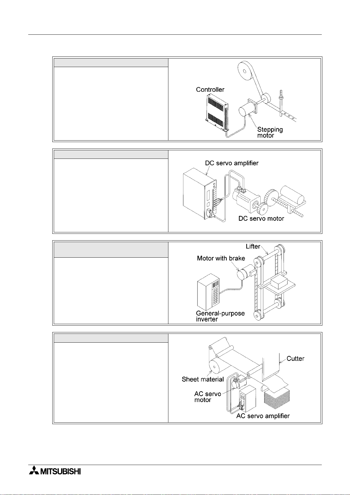
Velocity
High speed
Speed reduction command
Dispersion in
speed reduction
distance
Dispersion
in stop
Time
Stop command
- If the required stop precision is not
satisfactory when stopping from the
normal operation speed, t he most effective
method to improve the stop precision is to
reduce the operation speed.
- However, if the operation speed is simply
reduced, the machine efficiency may also
be reduced. In actual operation, the motor
speed can be reduced fro m high sp eed to
low speed once, then the motor stopped.
1-5
Page 18

Positioning Control The World of Positioning Control 1
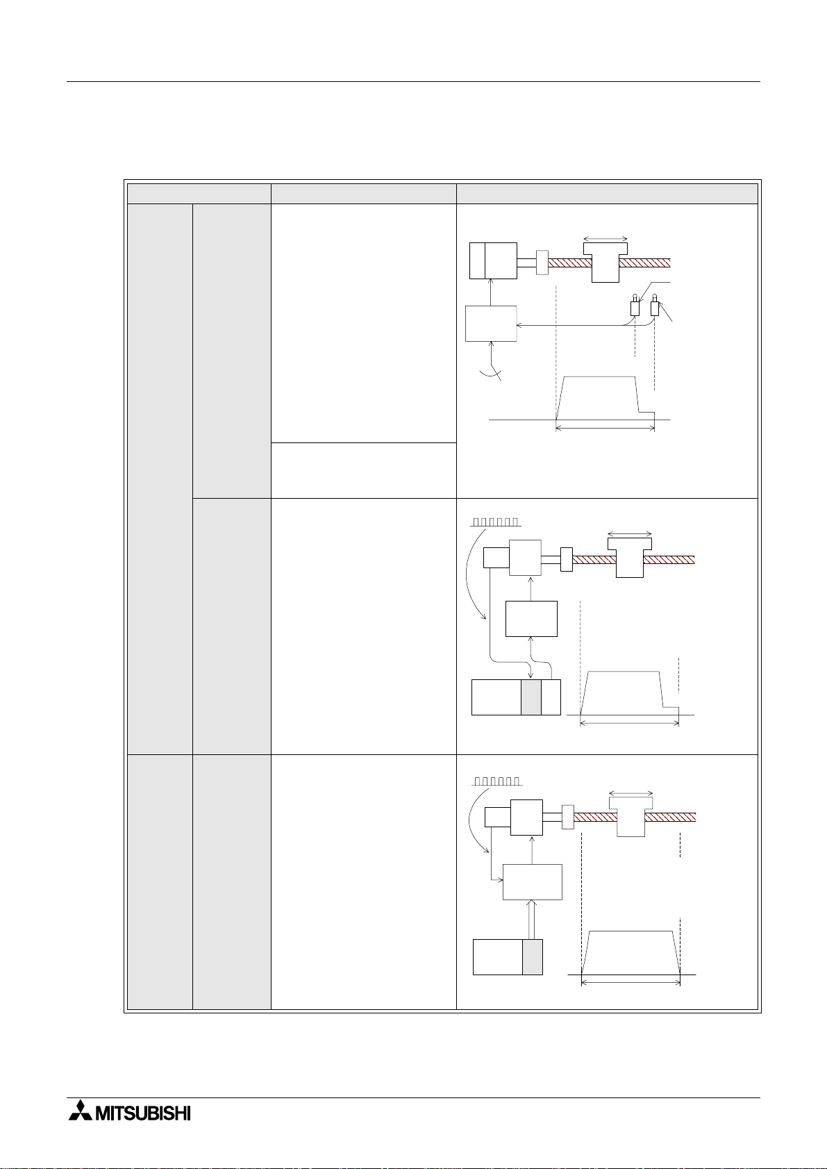
< Pulse count method >
- When a pulse encoder is attached to a moving par t, and the mot or speed is c ontrol led by
a number steps while the pulse number is counted, the movement qu antity per pulse is
determined in accordance with the relationship between the pulse number generated by
one rotation of the encoder, and the movement quantity of the mov ing part (workpiece)
realized by one rotation of the motor. The movement quantity per pulse is regarded as
the minimum unit for the stop command.
- However, the coasting distance at stop is not eliminated.
< Pulse command method >
- In this method using a servo system, the weak points described above are improved. A
pulse encoder is attached to the servo motor, detecting the motor rotation quantity
(workpiece movement distance), to continuously and directly control the speed from the
high-speed operation to the t arget p osit ion, which all ows the wor kpiece t o stop wi th good
precision.
- As the coasting distance at stop is eliminated, the positioning precision is improved.
1-6
Page 19

Positioning Control Positioning by AC Servo System 2
1 The Wor l d of Positioning Control
2 Positioning by AC Servo System
3 Components of Positioning Control and Their Roles
4 Advanced Positioning
5 Actual Positioning
6 Product Line up
A Appendix A: Tentative Selection of Motor Capacity
Page 20

Page 21
Positioning Control
2. Positioning by AC Servo System
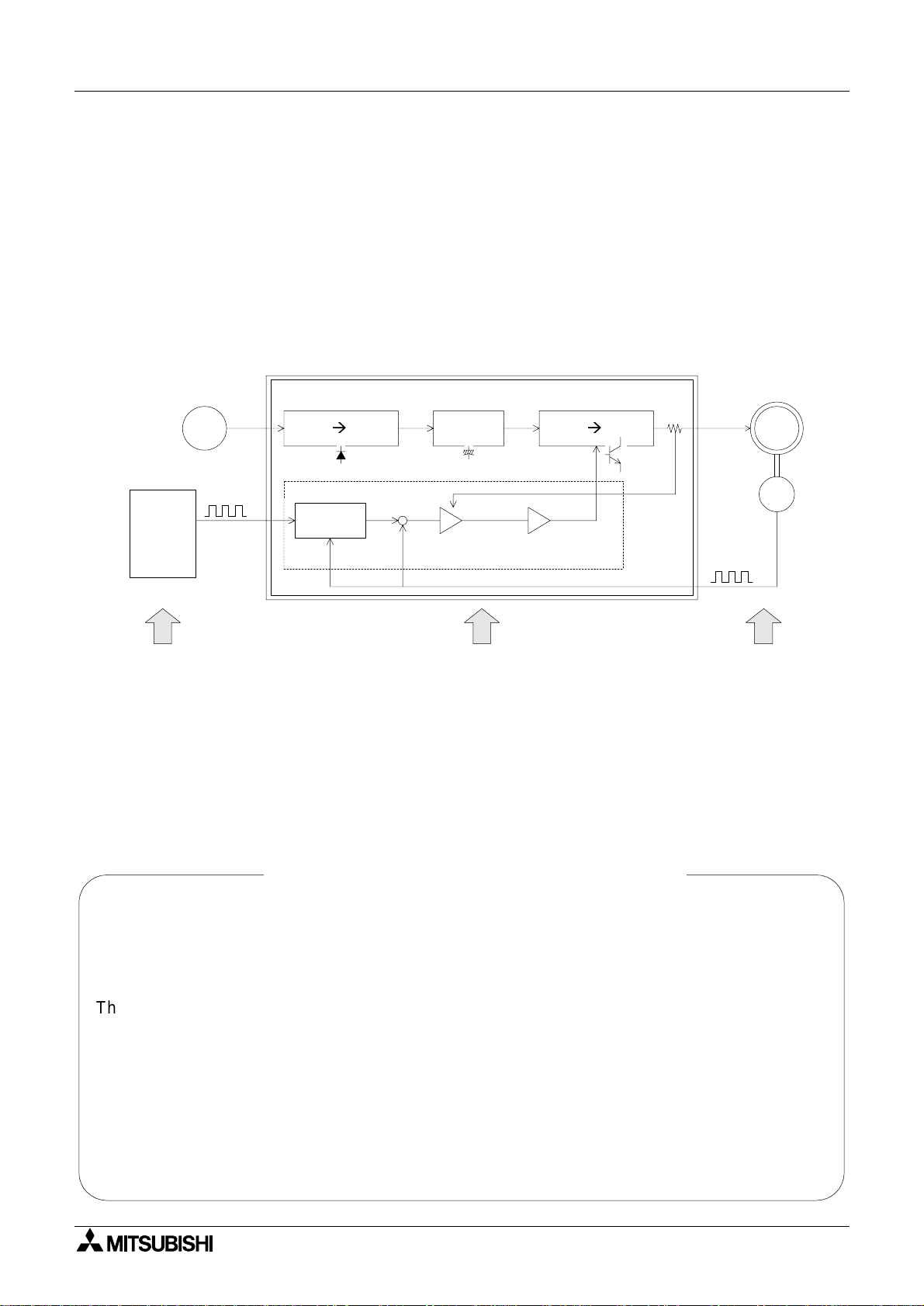
2.1 When an AC servo system is introduced
• Positioning can be performed by many diversified methods. Recently, AC servo methods
which offer many advantages are often introduced.
• In the positioning system of an AC servo method, a position controller, servo amplifier and
servo motor are generally required. The representative system configu ration is shown
below.
Servo amplifier
Commercial
power supply
Converter
Smoothing
circuit
Inverter
DC ACDCAC DC
Positioning by AC Servo System 2
Servo
motor
SM
Command
pulse
Position
controller
The position controller
generates a specified
quantity of forward rotation
(or reverse rotation) pulses at
a specified frequency.
Deviation
counter
Why is the AC servo system attracting attention?
Speed
command
Current
control
The command pulse number
is subtracted by the feedback
pulse number, and the speed
command to drive the servo
motor is made from the
deviation (accumulated pulse
number).
When the accumulated pulse
number becomes 0, the servo
motor stops.
PWM (pulse width
modulation) control
AC servo systems are easier to h andle than
hydraulic equipment.
Feedback
current
Feedback
The servo motor is equipped
with a built-in encoder (pulse
generator), dedicated to high
speed response, and suitable
to positioning control.
PLG
Encoder
pulse
The AC servo system satisfies the needs for
multi-model small-lot production through only
simple changes in the program.
As an AC servo system can generate large
torque, it can satisfy the needs for down sizing
and high power.
- Release from oil management
Robots in conjunction with an AC ser vo system
can satisfy the needs for labor saving and
automation.
- Release from dangerous, hard and dirty
working environments
2-1
Page 22
Positioning Control Positioning by AC Servo System 2
In the latest AC servo systems, conventional wea k points have been improved as follows.
- Though the latest systems are completely digital, they are equipped with parameters in
conformance to diversified mechanical specifications and electrical specifications so that
simple setting is possible.
- As frequent operation is enabled by a low inertia motor, the maximum torque is
increased and the system can be applied to diversified machines.
- The latest systems are equipped with an auto tuning function, with which the servo
amplifier automatically detects the load inertia moment and adjusts the gain. This is
possible even if the load inertia moment is unknown.
Aspects described below are now incorperated to AC serv o systems which offer marked
improvements from previous products.
In FA work place, a downsized AC servo
system occupying less space is required!
In accordance with sever operation
conditions, a tougher AC servo system is
required!
An AC servo system anyone can handle
easily is required! Even if the
performance is good, the AC servo
system cannot be accepted if it is difficult
to handle.
Compact and light servo
system
Robust servo system
Easy servo system
An AC servo system givi ng suf f icie nt cost
performance is required!
Good cost performance servo
system
2-2
Page 23
Positioning Control Positioning by AC Servo System 2
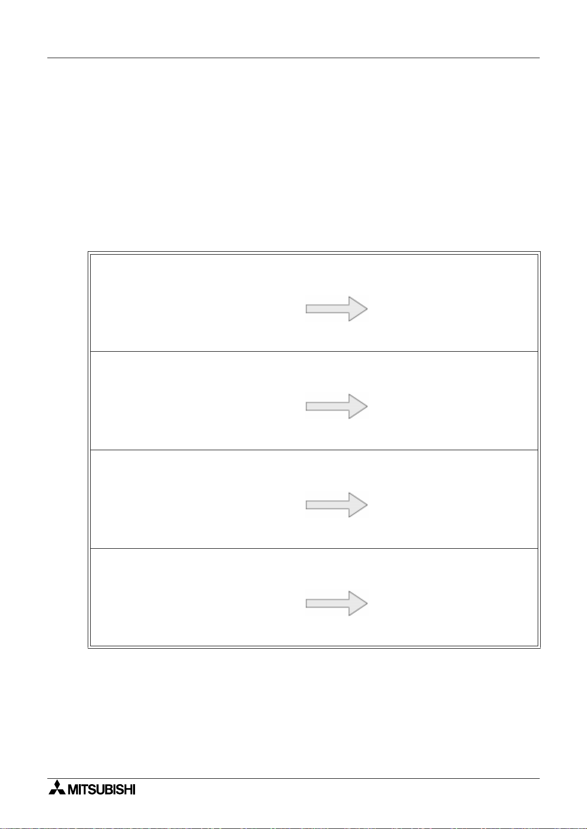
2.2 Examples of AC servo systems
• Positioning indicates the operation to move an element, such as a workpiece or tool (dril l or
cutter) from a certain position (point) to another target position (point) and stop it with high
efficiency and high precisi on.
• In other words, the principle of positioning is the control of speed in accordance with the
position, performed to promptly eliminate the remaining distance to the target position. The
flexibility to change the target position electrically and easil y is an important requirement.
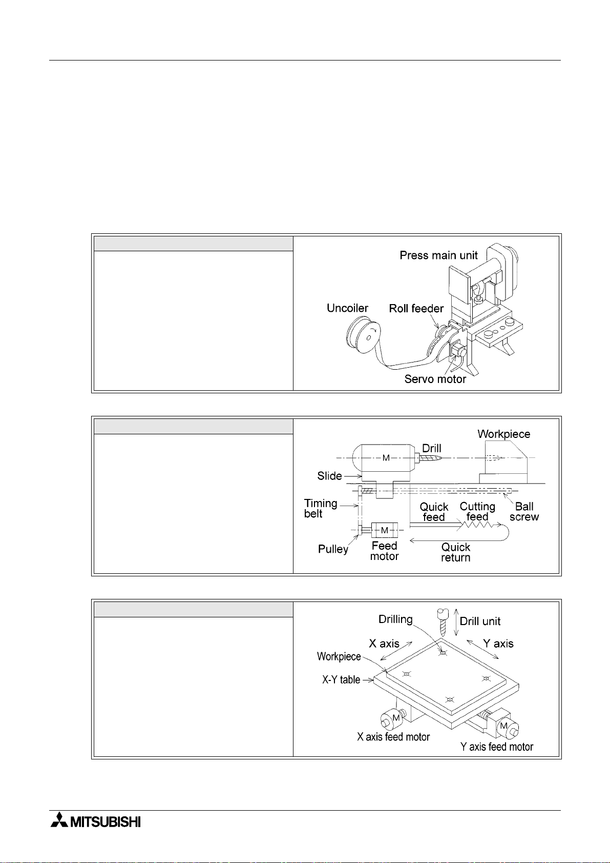
• Several cases of positioning using an AC servo motor are systemati cally shown below.
Constant feed
In the press/shear process for cutting,
punching, etc., the processed material is
positioned with high precision to produce a
constant sized product.
Tapping
In order to tap a workpiece, "1. Quick
feed", "2. Cutting feed" and "3. Quick
return" are repeatedly performed.
Drilling in steel sheet
In order to perform processing on a flat
face, positioning with high precision is
performed by two motors (X axis feed
motor and Y axis feed motor).
2-3
Page 24

Positioning Control Positioning by AC Servo System 2
Index table
The position of the circular table is
indexed.
The index position is set on the outside
(digital switch) or the inside (program).
Shortcut drive is performed depending on
the index position.
Lifter moving-up/down
As negative load is applied on the servo
motor in positioning of the lifter in the
vertical direction, a regenerative option is
used also.
In order to hold the lifter stationery and
prevent drop of the lifter by power
interruption, a servo motor with
electromagnetic brake is used.
Cart travel control
A servo motor is mounted in the travel cart
as the drive source.
A mechanism such as rack and pinion is
adopted to prevent slippage between the
wheels and rails.
Carrier robot
After the conveyor stops, the 2-axis servo
system and the arm lifting mechanism
transfer workpieces to a palette.
The workpiece input positions on the
palette can be set to many points so that
setup change can be easily performed,
even if the palette position and the palette
shape change.
2-4
Page 25

Positioning Control Components of Positioning Control and Their Roles 3
1 The Wor l d of Positioning Control
2 Positioning by AC Servo Sys tem
3 Components of Positioning Control and Their Roles
4 Advanced Positioning
5 Actual Positioning
6 Product Line up
A Appendix A: Tentative Selection of Motor Capacity
Page 26

Page 27

Positioning Control
Components of Positioning Control and Their Roles 3
3. Components of Positioning Control and Their Roles
Positioning control requires a number of components such as a positioning controller, servo
amplifier, servo motor and drive mechanism. This section describes the role of each
component.
3-1
Page 28

Positioning Control Components of Positioning Control and Their Roles 3
Position controller
• Outputs the positioning speed
and the movement quantity in
command pulses to the servo
amplifier.
• Transfers signals between the
programmable controller.
• Controls return to the zero point.
Near point dog signal
In some types, the li mit switc h signal
is wired to the posit i on controller.
Main circuit
Position controller
Converter
Positioning
command
control
Command
pulse
AC DC DC DC AC
AC power
supply
Smoothing
circuit
Power board
• Improves the power factor
and cuts noise.
• Protects the power circuit.
Servo amplifier
Regenerative
brake
Inverter
Dynamic
brake
R
Parameter
Pulse
magnification
Zero point
return
control
Servo
ready
(Electronic gear)
Counter clear
Zero point signal (PG0)
Operation equipment
• Give inputs for manual/automatic
mode, start/stop, zero po int return
command, manual forward rotation/
reverse rotation and manual pulse
generator to the positioning
controller.
Deviation
counter
Speed
command
Current
control
PWM (pulse width
modulation) control
Feedback pulse
Feedback
current
Servo amplifier
• Rectifies the AC power of the main circuit into
the DC power in the converter, and smooths it in
the smoothing circuit.
When the DC power is converted into AC power
in the inverter, the current supplied to the servo
motor is changed by the P WM (pulse width
modulation) control in the contr o l circuit.
• The deviation counter receives and counts the
command pulses from the positioning controller,
subtracts the feedback pulses from them, then
drives the servo motor until the accumulated
pulse number becomes 0.
3-2
Page 29

Positioning Control Components of Positioning Control and Their Roles 3
g
g
g
g
g
g
g
g
g
Servo motor
• Dedicated to hi
positionin
maximum torque and wide variable speed ran
1/1 or more (1/1,000 to 1/5,000).
Servo motor
In the case of large motor
Cooling fan
Servo
motor
SM
Encoder
PLG
(pulse
generator)
h speed response optimal to
control, has large start torque, large
When a moving element goes beyond a limit
switch (LS), the motor stops.
Drive mechanism
Limit switch
(LS)
Speed
reducer
Near point
dog switch
e
Moving element
Ball screw
Limit switch
(LS)
When
required
Electromag
netic brake
Hand held
Programmer
Setting / display unit
• Used to write pro
position controller, allows
settin
and display of the data.
Personal
Computer
rams to the
Auxiliary device such as c huck, drill and cylinder
Sensor, actuator,
auxiliary device
• The actuator (moving part drive
mechanism) is equipped with
speed reducer, timin
screw and limit switch.
Graphic
Operator
Terminal
• Diversified auxiliary devices are
also controlled in accordance with
positionin
.
• The PLC or the positionin
controller also controls a uxiliary
devices.
• The auxiliary device operation
completed si
PLC or the position controller.
belt, ball
nal is output to the
3-3
Page 30

Positioning Control Components of Positioning Control and Their Roles 3
3.1 Positioning controller
As the positioning con troller gives position comma nds to the servo amplif ier, positioning
programs should be created, and parameters defined. The contents related to programs a nd
parameters are described below.
3.1.1 Command pulse and feed quantity
There are the following three types of command pulse output modes.
- PLS/SIGN mode
- CW/CCW mode
- A phase/B phase mode
From the three, the CW/CCW mode is picked up for explanation.
• When the servo motor encoder generates 8,192 pulses for one rotation, the command
pulse number "8,192" should be output to rotate the servo motor by 1 rotation. The
workpiece feed quantity is in proportion to the puls e number.
< Forward rotation command >
Forward rotation pulse output
Reverse rotation pulse output
< Reverse rotation command >
Forward rotation pulse output
Reverse rotation pulse output
3.1.2 Command pulse and feed speed
• When the servo motor encoder generates 8,192 pulses for one rotation, the command
pulse frequency (speed) "8,192 pulses/s" should be output to rotate the servo motor by 1
rotation per second.
Forward rotation
pulse output
R e v ers e ro ta tio n
pulse output
0
1
0
12
0
-1 -2
2
Pulse number output per
second (frequency)
(8192) pulses
(-8192) pulses
(
8192)
pulses
• Decrease the pulse frequency to rotate the servo moto r at lower speed.
• Increase the pulse frequency to rotate the servo motor at higher speed.
3-4
Page 31

Positioning Control Components of Positioning Control and Their Roles 3
3.1.3 Setting the acceleration/decelerat ion time
• When the start command is given, acceleration, operation at constant speed and
deceleration are performed for positioning. Set the accelera tion time and the deceleration
time in the parameters.
Parameter:
Speed
Max. speed
Positioning speed
Actual
acceleration
time
Parameter:
Acceleration
time
• This operation pattern is effective during return to the zero point, positioning and jog
operation.
3.1.4 Backlash correction functio n
• The positioning controller can output excessive pulses, only when the movement direction
is inverted so that the backlash of the mechanical system is cor rect ed.
< Backlash correction >
Backlash
Parameter:
Deceleration
time
Table
Feed screw
Actual
Time
deceleration
time
3-5
Page 32

Positioning Control Components of Positioning Control and Their Roles 3
3.1.5 Zero point return function
• There are two types of servo motor encoders, incremental type (pulse count method) and
absolute type (absolute position detection method).
• Incremental type is constructed so that the current value stored in the position controller
does not increase or decrease, even if the workpiece stop position changes by some
reason while the power is turned off, theref ore the positioning address is not assured.
• Accordingly, when the power is turned on, the machine should be moved to the reference
point to update the zero point address. This operation is called return to zero point.
• Absolute type is constructed so that the current value stored in the position controller
increases or decreases if the workpiece stop positi on changes whil e t he power i s turned of f,
thus the positioning address is assured. Accordingly, when the power is turned on, return to
the zero point is not required.
However , when the machine is used for the first time, it should be returned to the zero point
so that it recognizes the zero point address.
Zero point
Deceleration time
Creep
speed
Zero point
Dog
switch
Dog
Clear signal
*
The return point of the dog switch should be adjusted
*
to a midpoint of the zero point signal (1 pulse per
rotation of the motor).
In this example, the dog length should not be less than
the deceleration distance of the machine.
return speed
Initial position
Zero point
return direction
Dog
Backward endForward end
< Operation to return to the zero point >
• The zero point return direction, return
speed, deceleration time and creep speed
are set by parameters in th e positioning
controller.
• There are several zero point return
methods.
For example, when the forward end of the
dog reaches the dog switch, the motor
resumes its creep speed. At the first zero
point signal after the dog re aches the
backward end, the deviation counte r clear
signal is output and the motor stops.
• The zero point address set by a parameter
is written to the current value register of
the position controller.
Limit
switch
Initial
position
Escape operation
Dog
switch
Zero point
• In some models, if the zero point return
operation is performed while the work
piece is stopped beyond the dog switch,
the machine moves once until the limit
switch is actuated, inverts the direction,
then returns to the zero point again (dog
search function, zero point return retry
function).
3-6
Page 33

Positioning Control Components of Positioning Control and Their Roles 3
3.2 Servo amplifier and servo motor
The servo amplifier controls the movement quantity and the speed in accordance with
commands given by the positioning controller. The servo motor transmits rotation to the drive
mechanism after receiving a signal from the servo amplifier.
3.2.1 Positioning control in accordance with command pulse
• By PWM (pulse width modulatio n) control, performed to the servo amplifier main circuit with
regard to the position co mmand and the speed command, in accordanc e wi th the command
pulses of the position controller, the servo motor is driven. The rotation speed and the
rotation quantity are fed back from the encoder attached to t he servo motor.
3.2.2 Deviation counter function
• The difference between the command pulses and the feedback pulses counted by the
deviation counter in the servo amplifier is cal led accumulated pulses.
• While the machine is operating at a constant speed, the accumulated pulse quantity is
almost constant. During acceleration and deceleration, the accumulated pulse quantity
changes more dramatically.
• When the accumulated pulse quantity becomes equivalent to or less than the specified
quantity (in-position set value) after command pulses have stopped, the servo amplifier
outputs the positioning completed signal.
The servo motor continues operation even after that. Then, when the accumulated pulse
quantity becomes 0, the servo motor stops.
The time after the servo motor outputs th e positioning completed signal, until it stops is
called stop settling time.
Speed
Accumulated
pulses
Stop settling time
3.2.3 Servo lock function
• The servo motor is controlled so that the accumulated pulse quantity counted in the
deviation counter becomes 0.
• For example, if an external force for forward rotation is applied on the servo motor, the
servo motor performs the reverse rotati on operation to eliminate the accumulated pulses.
Command speed
Motor speed
The accumulated pulse quantity is 0, and
positioning is completed.
Time
Accumulated pulses in deviation counter Servo motor
Minus pulses Reverse rotation operation
Plus pulses Forward rotation operation
0 (zero) Stop
3-7
Page 34

Positioning Control Components of Positioning Control and Their Roles 3
3.2.4 Regenerative brake function
• During deceleration, because the servo motor rotates by the load inertia of the drive
mechanism, it functions as a generator and electric power returns to the servo amplifier.
The regenerative resistor absorbs this electric power, and functions as a brake (called a
regenerative brake.)
• The regenerative brake is required to prevent regenerative over voltage in the servo
amplifier when the load inertia is large and th e operat ion is frequently performed.
• The regenerative resistor is required when the regenerative power generation quantity
during deceleration exceeds the allowable regenerative electric power of the servo
amplifier.
3.2.5 Dynamic brake function
• When a circuit inside the servo ampl ifi er is di sabled b y a power int er rupti on in the AC po wer
of the main circuit or actuation of the protective circuit, the terminals of the servo motor are
short-circuited via resistors, the rotation energy is consumed as heat, then the motor
immediately stops without free run.
• When the motor stops by elimination of the rotation energy, the brake is not effective and
the motor runs freely.
Main
circuit
AC power
supply
NFB
Position
controller
rotations of motor
R
Converter
S
AC DC
T
Deviation
counter
Number of
Inverter
DC AC
D/A
conversion
Motor stop characteristics when the
dynamic brake is actuated
When the dynamic brake
is not actuated
U
V
W
These contacts of the
dynamic brake turn ON
when the power is
interrupted.
SM PLG
Power: OFF
Contacts of dynamic brake: ON
Time
3-8
Page 35

Positioning Control Components of Positioning Control and Their Roles 3
3.3 Drive mechanism
The drive mechanism converts the rotation motion of the servo motor into the reciprocating or
vertical motion through a speed reducer, timing belt, ball screw, etc. to move the machine.
3.3.1 Concept of drive system movement quantity
1) Representative positioning system using AC servo motor
*2 In the structure design, parameters (such as ∆ and V
advance.
V
0
Moving part
P
f
Encoder
Servo
motor
N
0
Servo
amplifier
f
0
Position
controller
Speed
reducer
1
n
P
B
: Movement quantity per pulse (mm/pulse)
D
: Moving part speed during quick feed (mm/min)
V
0
: Number of rotations of motor during quick feed (r/min)
N
0
: Lead of ball screw (mm/rev)
P
B
1
: Speed reduction ratio
n
: Feedback pulse number (pulse/rev)
P
f
: Command pulse frequency during quick feed (pulse/s)
f
0
D
S
: Movement quantity per rotation of motor (mm/rev)
) should be determined in
0
a) The servo motor stops with the precision (±∆ ) which is within ±1 pulse against the
command pulse.
b) The movement quantity of the work piece is
"Output pulses from position controller × ∆ ".
The moving part speed is
"Command pulse frequency from position controller × ∆ ".
c) Either "mm", "inch", "degree" or "pulse" can be selected as the positioning command
unit. Accordingly, when data suc h as the movement qu antity per pu lse, posit ioning speed
or the positioning address in accordance with the positioning command unit are set, the
pulse trains calculated inside the positioning controller are output for the target address,
and positioning is performed.
3-9
Page 36

Positioning Control Components of Positioning Control and Their Roles 3
2) Examples of calculation equations
a) Movement quantity per rotation of motor (mm/rev)
Movement
quantity per
Lead of ball screw (mm/rev) Speed reduction ratio=
×
rotation of motor
b) Number of rotations of motor (rev/min.)
(The maximum number of rotations is realized during quick feed.)
Number of
rotations of
motor
Note:The number of rotations of a motor during quick feed should not exceed the rated
number of rotations.
The moving part speed during quick feed should not ex ceed the parameter "speed limiting
value" of the positioning controll e r.
a) Movement quantity per pulse (mm/pulse)
Movement
quantity
per pulse
b) Command pulse frequency during quick feed (pulse/s)
Command
pulse
frequency
during
quick feed
Moving part speed during quick feed (mm/min)
=
Movement quantity per rotation of motor
Movement quantity per rotation of mot or (mm/rev)
=
Feedback pulse number (pulse/rev)
Number of rotations of motor
during quick feed (r/min)
=
60
Movement quantity per
×
rotation of motor (mm/rev)
Movement quantity per pulse
×
(mm/pulse)
Rated number of
<
rotations of
=
servo motor
Electronic
×
gear ratio
Note:The command pulse frequency during quick feed should not exceed the maximum input
pulse frequency of the servo amplifier.
a) Maximum movement distance
In each of the absolute and incremental methods, the entire movement distance should
not exceed the maximum pulse number of the positioning contro ller.
3-10
Page 37

Positioning Control Components of Positioning Control and Their Roles 3
3.3.2 Setting the target position
In positioning control, the target position can be set by the following two methods.
(Available command units are "mm", "inch", "degree" or "pulse".)
1) Absolute method
In this method, a point (absolute address) is specified for positioning while the zero point is
regarded as the reference. The start point is arbitrary.
Address
100
Address 100
Start point
End point
Address 150
Address 300
Address 150
Address 100
Address 150
0
Zero point
100
Point A
150
Point B
300
Point C
2) Incremental method
In this method, positioning is performed through specification of the m ovement direction
and the movement quantity while the current stop position is regarded as the start point.
Movement quantity
0
Zero point
+100
Movement quantity +100
Movement quantity -150
Movement quantity -100
100
Point A
Movement quantity
Movement quantity +100
Movement quantity +50
150
Point B
-100
300
Point C
Start point
End point
3-11
Page 38

Positioning Control Components of Positioning Control and Their Roles 3
3-12
Page 39

Positioning Control Advanced Positioning 4
1 The Wor l d of Positioning Control
2 Positioning by AC Servo Sys tem
3 Components of Positioning Control and Their Roles
4 Advanced Positioning
5 Actual Positioning
6 Product Line up
A Appendix A: Tentative Selection of Motor Capacity
Page 40

Page 41

Positioning Control
4. Advanced Positioning
4.1 Interpolation control
The interpolation function controls two or more axes alternately or simultaneously. Linear
interpolation and circular interpolation are usually offered.
Advanced Positioning 4
< 2-axis linear interpolation >
Y
axis
Start point
< 3-axis linear interpolation >
Z axis
Start point
X axis
Speed change in X axis
Speed
End point
End point
X axis
Y axis
< Linear interpolation >
- Linear interpolation controls two or
more axes so that the start point and
the end point (target position) are
connected in the shortest way.
- In this case, the locus is linear.
- Models applicable to 2-axis linear
interpolation control
[FX-20GM,E-20GM,FX
2N
-20GM
AD75P2/P3,AD75M2/M3,
QD75P2/P4,QD75D2/D4,
A171SH,A172SH,A173UH,A273UH]
- Models applicable to 3 or 4-axis linear
interpolation control
[A171SH,A172SH,A173UH,A273UH]
- Application examples
[Drilling on steel sheet, insertion of
parts into PCB, automatic warehouse,
automatic crane, etc.]
Time
4-1
Page 42

Positioning Control Advanced Positioning 4
< Circular interpolation
when an auxiliary point is specified >
Auxiliary
Y
line
axis
Start point
< Circular interpolation when the radius is specified >
Y
axis
Start point
< Circular interpolation when the center is specified >
Y axis
End point
X axis
End point
Radius
X axis
< Circular interpolation >
- Circular interpolation controls two or
more axes so that the start point and
the end point (target position) are
connected with circular arc.
- As there are innumerable number of
arc locus connecting two points, an
auxiliary point, the arc radius, the
center or the direction should be
specified in addition to the start point
and the end point to determine the
circular arc.
- Models applicable to 2-axis circular
interpolation control
[FX-20GM,E-20GM,FX
2N
-20GM
AD75P2/P3,AD75M2/M3,
QD75P2/P4,QD75D2/D4,
A171SH,A172SH,A173UH,A273UH]
- Models applicable to 3-axis circular
interpolation control
[A171SH,A172SH,A273UH]
Speed
Center
Start point
Speed change in X axis
End point
X axis
- Application examples
[Steel sheet fusing, welder, applicator,
crane, etc.]
Time
4-2
Page 43

Positioning Control Advanced Positioning 4
4.2 Other controls
In some models, controls in accordance with diversified special needs such as speed control,
position follow-up co ntrol and three-dime nsional interpolation c ontrol shown below are
available.
< Speed control >
- After movement starts from the start
point, it then continues at the
Start point
X axis
Speed change in X axis
Speed
specified speed until the stop
command is input.
- Applicable models
[FX-1PG,FX
2N
-1PG
AD75P1/P2/P3,AD75M1/M2/M3,
QD75P1/P2/P3,QD75D1/D2/D3,
A171SH,A172SH,A173UH,A273UH]
- Application examples
[Conveyor, carrier unit, roller feed,
crane, etc.]
Speed
Constant
quantity
Start point
Speed change in X axis
End point
Time
X axis
< Constant feed >
- After start, a workpiece moves by the
specified constant quan tity, but the
current value do es not increase even
if the operation is repeated.
- Applicable models
[FX-10GM,FX-20GM,E-20GM,
2N
FX
-10GM,FX2N-20GM
AD75P1/P2/P3,AD75M1/M2/M3,
A171SH,A172SH,A273UH]
- Application examples
[Press, shear, conveyor, transfer unit,
assembly line, etc.]
Time
4-3
Page 44

Positioning Control Advanced Positioning 4
Y axis
Speed
1000
mm/min
Start point
300
mm/min
5000
mm/min
Speed
changeover point
Speed change in X axis
End
point
X axis
< Speed changeover control >
- From the start point which is the
current stop address, positioning
control is performed to the e nd point
address while the speed changes at
speed changeover points.
- The address for speed change can be
determined in advance.
- Applicable models
2N
[FX
-1PG,FX-10GM,FX-20GM,
E-20GM,FX
2N
-10GM,FX2N-10GM,
AD75P1/P2/P3,AD75M1/M2/M3,
QD75P1/P2/P4,QD75D1/D2/D4,
A171SH,A172SH,A173UH,A273UH]
- Application examples
[Conveyor, carrier unit, roller feed,
crane, etc.]
Y axis
Speed
Passing point
Start point
Radius
Passing point
Speed change in X axis
Time
End
point
X axis
< Constant speed control >
- From the start point which is the
current stop address, positioning
control is performed to the end point
address at an equal speed by way of
passing points.
- Passing points make small circular
arc.
- Applicable models
[AD75P1/P2/P3,AD75M1/M2/M3,
QD75P1/P2/P3,QD75D1/D2/D4,
A171SH,A172SH,A273UH]
- Application examples
[Steel sheet fusing, welder, applicator,
crane, transfer robot, etc.]
Time
4-4
Page 45

Positioning Control Advanced Positioning 4
Y axis
Speed
Change
point
Start
point
Speed change in X axis
Changed
end point
Original
end point
X axis
Time
< Position follow-up control >
- If the end point address is changed
while a positioning control movement
is being executed, positioning is
controlled to the new end point
address.
- Applicable models
[A171SH,A172SH,A273UH]
- Application examples
[Product follow-up type, application
line and welding line]
X axis
Speed
Z axis
Start point
Speed change in the Y axis
Time
End
point
Y axis
< Three-dimensional interpolation control >
- From the start point which is the
current stop address, 3-axis linear
interpolation control and 3-axis
circular interpolation control are
performed to the end point address by
way of passing points.
- Applicable models
[A171SH,A172SH,A273UH]
- Application examples
[Assembly robot, welding robot,
application robot and transfer robot]
4-5
Page 46

Positioning Control Advanced Positioning 4
4-6
Page 47

Positioning Control Actual Positioning 5
1 The Wor l d of Positioning Control
2 Positioning by AC Servo Sys tem
3 Components of Positioning Control and Their Roles
4 Advanced Positioning
5 Actual Positioning
6 Product Line up
A Appendix A: Tentative Selection of Motor Capacity
Page 48

Page 49

Positioning Control
5. Actual Positioning
Terms required for positioning control have been explained in the first three sections.
In this section, let’s experience actual positioning control based on the knowledge you have
learned so far.
2N
The position controller FX
can also be used in place of the FX
5.1 Demonstration Equipment
Two different levels of demonstration equipment can be u sed for this example, depend ing on
what is available. The basic set utilizes the live monitoring function of the FX-PCS-VPS
software, where as, the more comprehensive set makes use of an X Y plotting table, to
actually see the axes move, and draw the resulting locus.
5.1.1 Basic Set
The demonstration items required for the basic set up are as follows;
2N
FX
-20GM
F2-422 CAB0 Communications cable
FX-232AW(C) Converter
FX-232 CAB-1 Communications cable
Personal computer
FX-PCS-VPS\Win software
-20GM is used for the demonstration as show below. An FX-20GM
2N
-20GM.
Actual Positioning 5
MITSUBISHI
AUTO
POWER
MELSECFX2N-10GM
READY
START
ERROR
STOP
CPU-E
ZRN
SVRDY
FWD
SVEND
MANU
RVS
PGO
DOG
FP
LSF
RP
LSR
CLR
X0
X1
X2
X3
Y0
Y1
Y2
Y3
Y4
Y5
PLC EXT
I/O MOTOR
5.1.2 Comprehensive Set
The demonstration items required for the comprehensive setup are as follows;
2N
FX
-20GM
F2-422 CAB0 Communications cable
FX-232AW(C) Converter
FX-232 CAB-1 Communications cable
Personal computer
FX-PCS-VPS\Win software
Plotter Communications cable (*1 Specific to plotter)
X Y Plotting table
MITSUBISHI
AUTO
POWER
MELSECFX2N-10GM
READY
START
ERROR
STOP
CPU-E
ZRN
SVRDY
FWD
SVEND
MANU
RVS
PGO
DOG
FP
LSF
RP
LSR
CLR
X0
X1
X2
X3
Y0
Y1
Y2
Y3
Y4
Y5
PLC EXT
I/O MOTOR
FX-422CAB0 F2-232CAB-1FX-232AW(C)
Plotter
X
Y
FX-422CAB0
F2-232CAB-1FX-232AW(C) Cable *1
5-1
Page 50

Positioning Control Actual Positioning 5
5.2 Operation of the demonstration equipment
Source the required demonstration equipment, and setup as in section 5.1. If a plotter is being
used refer to the operations manual for the particular unit and setup accordingly.
Throughout this example it is assumed that you will have read and understood both the FX
20GM Hardware / Programm ing manual (JY992D77801) and the FX-P CS-VPS/Win-E
softtware manual (JY992D86801) or you will have then close at hand for reference.
2N
For this example we will use the basic setup of Personal computer and FX
Let’s draw the locus shown below dr iven by the X and Y axes simult aneously. The output Y0 is
added to imitate a pen, or other end effector.
-20GM.
2N
-
D
Start point
A
G
C
H
End Point
B
A: Start point, this point can be anywhere.
B: (0,0), Zero point, wait for 2 seconds.
C: (80,100), Output Y0 turns ON, wait for 2 seconds.
D: (110,200).
E: (200,200).
E
F
F: (200,100).
G: (150,100), Output Y0 turns OFF, wait for 2 seconds.
H: (150,70), End point.
A to B - Return to Electrical Zero.
B to C - High speed positioning.
C to D - Linear interpolation.
D to E - High speed positioning.
E to F - Clockwise circular interpolati on.
F to G - High speed positioning.
G to H - High speed positioning.
5-2
Page 51

Positioning Control Actual Positioning 5
5.2.1 Program example
The program below demonstrates basic positioning using the FX
2N
-20GM. As this program is
designed to be used without a mechanical plotter, the electrical zero point is used for
reference.
Many programs can be stored in a GM unit at one
time. This example uses program number 0.
This command is to move from the start point, to
the electrical zero point
Here the program waits for 2 seconds, using a
10ms timer.
This command indicates the rapid command to
position C.
Here Y0 is turned on, to mimic the use of an end
effector tool.
This timer allows a tool to be activate d, or an
operation executed.
This command is the start of a continuous steady
path, first using linear interpolation to position D
To position E, only the X axis need move.
For a smooth arc, circular interpolation is use d.
This example shows the start and end positions
(F), as well as the radius and a speed f.
To position G, only the X axis need move.
Here Y0 is turned off, to mimic the the end of the
end effector use.
Again a timer related to the operation above.
This command rapidly moves only the Y axis a
short distance to position H.
The end of the program, and a wait for the next
start command.
5-3
Page 52

Positioning Control Actual Positioning 5
5.2.2 Writing the program
Using FX-PCS-VPS\Win-E, re-create the flow chart program shown in section 5.2.1.
If assistance is required in the operation of the software, please refer to the Software manual
JY992D86801.
When opening a new file in VPS, choose ‘FX(2N)/E-20GM with simultaneous 2 axis’
The example program is designed to utilize the real time monitor function of VPS software. If a
mechanical plotter is being used substitute the ‘DRV Ret’ command for a ‘DRVZ’, return to
origin command. Be sure to set up the plotter in accordance with the instructions and
guidelines applicable to and supp lied with your specific plotter.
Along with the Flow chart, create a monitoring window similar to the one shown below.
All of the items on the monitoring window can be found under the insert tab on the main menu
at the top of the screen.
Items inserted include:
Current Position
Plotting (double click on plot area to change the scale)
Device Status (Y0)
Manual Operation (Start, Stop, Jog -, Jog +, for both X and Y axes, each inserted separately)
FX-GM Status
Plus, a rectangle from the drawing tool bar, to highlight the Y0 indicator .
5-4
Page 53

Positioning Control Actual Positioning 5
5.2.3 Parameters
In addition to the preparation of a positioning program, diversified parameters should be set in
the FX
2N
-20GM.
In this example, only a few parameters need be set. If a plotting table is used, the parameters
should be set in accordance with its mechanism. The se will depend upon the spe cific plotter
type, and should be found in the documentation provided with the plotter.
Below are the four positioning parameter w indows from VPS, cop y these settings into your
program.
The values for both the X and Y axes are the same for all parameters.
The system of units we will be using is both mechanical and motor, so that the position can be
controlled in mm, deg, 1/10 inch etc. while the speed can be controlled by the number o f
pulses. The system units should be set to ‘mm, and all other options left as default.
So that we can follow the path created by the FX2N-20GM, the Max speed should be set quit e
low. Intern both the JOG speed and the Interpolation value must be reduced. In practice, it is
impossible to have the JOG speed faster than the Max speed setting.
Remember to change the setting for the Y axis also.
5-5
Page 54

Positioning Control Actual Positioning 5
As we will not be connecting any mechanical hardware to the FX2N-20GM, the li mit switch and
DOG switch settings do not require setting. We do how ever need to reduce the Creep speed
and the Zero return speed.
All of the parameter settings o n this screen window can be left as their def ault values, they are
already optimized for our program.
If a plotter table is be ing used, all o f the above p arameters will need to be checke d before
power ON, or operation.
5-6
Page 55

Positioning Control Actual Positioning 5
5.2.4 Operation
Now that your program has been written, check the communication cables between the FX
20GM and PC, then download your program to the FX
2N
-20GM. Make sure that the GM unit is
2N
in ‘MANU’ mode before download, or it will be impossible to communicate.
In VPS, start the Monitor mode by clicking the Monitor icon on the tool bar, shown below.
Monitor icon
The Monitor mode screen will appear. Here, the flow icon menu and program map have been
removed. Three windows are displayed;
2N
Monitoring window: This is the window you c reated, and will use to cont rol t he FX
-20GM and
view the resulting locus.
Sub-task - Monitor mode: This window in not needed as we do not use any sub rout ines in our
programs, it can be minimized to create more space on the screen.
X-axis and Y-axis - Monitor mode - At first this window will be empty, but as soon as you start
your program, the flow chart will appear, and scroll through, keeping the live instruction
highlighted in red.
After minimizing the Sub-task monitor window, resize the Monitoring window and then the Xaxis and Y-axis window.
-
Now you are ready to begin.
Firstly set the start point, thi s can be done be either using the X and Y axis JOG buttons, or by
double clicking on the current position display.
Double clicking the current position display brings
up this window;
For X, replace 0 with 50, and click on the ‘Write to
FX-GM’ button.
For Y, replace 0 with 125, and click on the ‘Write to
FX-GM’ button.
As you write that data to the GM, you will see a
red line being draw n on th e plot in the M onitoring
window. This shows the current position.
We want a clean plot area to begi n with , so double
click on the plotting area, and click on the clear button.
5-7
Page 56

Positioning Control Actual Positioning 5
The next step, it to switch the FX2N-20GM to ‘AUTO’ mode, so that the program can be
executed.
Finally, on the Monitor screen click on either the X or Y axis start buttons. It does not matter
which one, as both will start the program. Sit back and see what you have produced.
Your screen should look similar to the one shown below, the plot should be identical.
To run the program again, set a new start position (or let it start from where it is), clean the plot
area, and press start.
If your plot does not look the same as the one above, check yo ur program against the one in
section 5.2.1.
If it does, now is the time to experiment some more. Try a new program, perhaps include subtasks and multiple flow charts . Only a sample of the functionality available in VPS has be used
in this example program, try using some of the other programming aspects.
5-8
Page 57

Positioning Control Product Line up 6
1 The Wor l d of Positioning Control
2 Positioning by AC Servo Sys tem
3 Components of Positioning Control and Their Roles
4 Advanced Positioning
5 Actual Positioning
6 Product Line up
A Appendix A: Tentative Selection of Motor Capacity
Page 58

Page 59

Positioning Control
6. Product Line up
We are offering diversified position controllers, servo amplifiers and servo motors. You can
select desired units in accordance with your system and application.
For the derails, refer to the catalog of each product.
6.1 Position controller
1) Outline of position controller models
In the position controller, the positioning function is built in or extended. For some position
controllers, an PLC executes positioning programs. Other position contro llers execute
programs using their unique positioning language without regard to any PLC.
Product Line up 6
FX Series
A Series
Q Series
Model name/unit
name
1S
/FX1N Series
FX
PLC
1-axis position
controller FX-10GM
2N
FX
-10GM
2-axis position
controller FX-20GM
2N
FX
-20GM
2-axis position
controller E-20GM
1-axis pulse output
block FX
1- to 3-axis position
controller AD75P1
to AD75P3
1- to 3-axis position
controller AD75M1
to AD75M3
1- to 4-axis position
controller QD75P1
to QD75P4
1- to 4-axis position
controller QD75D1
to QD75D4
2N
-1PG
Positioning
language
FX sequence
language
Dedicated
language
FX sequence
language
A sequence
language
+
Positioning
data
Q sequence
language
+
Positioning
data
Outline
Pulse output type for independent 2 axes
Through application instructions in the PLC main unit,
absolute position detection, return to mechanical zero
point and one-speed constant positioning are
available.
Pulse output type for 1
axis
Pulse output type for 2
axes
Independent 2 axes or
simultaneous 2 axes
(linear interpolation,
circular interpolation)
Pulse output block for FX
Used as an extension block
Pulse output type for 1 to 3 axes
Simultaneous 1 to 3 axes, independent 1 to 3 axes, 2axis linear interpolation, 2-axis circular interpolation
SSC net connection type for 1 to 3 axes
Simultaneous 1 to 3 axes, independent 1 to 3 axes, 2axis linear interpolation, 2-axis circular interpolation
Pulse output type for 1 to 4 axes (open collector
output)
Simultaneous 1 to 4 axes, independent 1 to 4 axes, 2
to 4-axis linear interpolation, 2-axis circular
interpolation
Pulse output type for 1 to 4 axes (differential output)
Simultaneous 1 to 4 axes, independent 1 to 4 axes, 2
to 4-axis linear interpolation, 2-axis circular
interpolation
Easy sequence function is
provided.
Bus connection to FX
Series PLC is available.
(Position controller can be
used independently also. )
Easy sequence function is
provided.
(Position controller can be
used independently also. )
2N
Series PLC
6-1
Page 60

Positioning Control Product Line up 6
Motion
controller
Model name/
unit name
A171SH
A172SH
A173SH
A273UH
Positioning language Outline
Language dedicated to servo system
[4-, 32-axis independent control, 2- to 4axis linear interpolation control, 2-axis circular interpolation control, speed control,
equal speed control, position follow-up
control]
NC language
[Control using G codes]
Dedicated robot
[Three-dimensional linear/circular interpolation control]
Mechanical support language
[Synchronous operation control]
A171UHCPU (512 I/O points):
4-axis control
A172SHCPU (512 I/O points):
8-axis control
A173UHCPU (2,048 I/O
points): 32-axis control
Servo amplifier
(0.05 to 55 kw are dedicated to
SSC net connection.)
A3UCPU (2,048 I/O points):
32-axis control
Servo amplifier
(0.05 to 0.6 kw allow built-in
type also.)
(0.05 to 55 kw are dedicated to
SSC net connection.)
Mechanical support language in motion controller
A new world of synchronous mechanism is open.
Programming in virtual world
By simply connecting and laying out a
transmission module and an output
module to a virtual main shaft on the
screen, while regarding diversified
synchronous mechanism as software
mechanical modules, you can easily
program a synchronous system.
6-2
Page 61

Positioning Control Product Line up 6
1) When and which position controller?
In addition to the PLC series, take into account the following contents to determine the
position controller to be used.
a) Determine the position controller to be used in accordance with the number of controlled
axes (motors).
1-axis control
2-axis control
3-axis control
Control of 4-
axes or more
Position controller dedicated to 1 axis
2N
FX-10GM, FX
-10GM, FX2N-1PG
AD75P1, AD75M1, QD75P1, QD75D1
Only 1 axis of 2-axis position controller
FX-20GM, E-20GM, FX
2N
-20GM, FX1S/FX1N Series PLC
AD75P2, AD75M2, QD75P2, QD75D2
2-axis position controller
2N
FX-20GM, E-20GM, FX
-20GM, FX1S/FX1N Series PLC
AD75P2, AD75M2, QD75P2, QD75D2
3-axis position controller
AD75P3, AD75M3
Combination of 1-axis position controller and 2-axis position controller
For 1-axis control, for 2-axis control
4-axis position controller
QD75P4, QD75D4, A171SH
Position controller for 4 axes or more
A171SH, A172SH, A173UH, A273UH -----
Combination of 1-axis position controller, 2-axis position controller
and 3-axis position controller
for 1-axis control, for 2-axis control, for 3-axis control
6-3
Page 62

Positioning Control Product Line up 6
b) Determine the position controller to be used in accordance with the output pulse
frequency.
However, the pulse frequency actually used inside the servo amplifier can be increased
by electronic gearing.
100kp/sec
200kp/sec
When the required command pulse is 100 kpps or less
2N
FX
-1PG, FX1S/FX1N Series PLC
When the required command pulse is 200 kpps or less
FX-10GM, FX-20GM, E-20GM, FX2N-10GM, FX2N-20GM
400kp/sec
1Mkp/sec
AD75P
When the required command pulse is 400 kpps or less
AD75P
When the required command pulse is 1 Mpps or less
AD75M
, QD75P
, QD75P
, A171SH, A172SH, A173UH, A273UH
c) Determine the position controller to be used in accordance with handli ng of the feedback
pulse.
Position
controller
Command
pulse
To servo amplifier
Servo
amplifier
Servo
motor
SM
The position controller only outputs pulses,
and does not check feedback pulses.
Accordingly, it is not confirmed whether or
not rotation in accordance with command
pulses is actually performed.
Position
controller
SSC net
Feedback
pulse
PLG
Encoder
To position controller
Servo
motor
Servo
amplifier
Feedback
pulse
SM
PLG
Encoder
FX-10GM, FX-20GM, FX
E-20GM, FX
1S
/FX1N Series PLC
FX
AD75P
2N
-10GM, FX2N-20GM,
, QD75P, QD75D
2N
-1PG,
The position controller checks feedback
pulses. Accordingly, it is confirmed whether
or not rotation in accordance with command
pulses is actually performed.
AD75M
, A171SH A172SH,
A173UH, A273UH
6-4
Page 63

Positioning Control Product Line up 6
6.2 Servo amplifier
1) Outline of serve amplifier models
Model name Outline
• DC 24V
• Size is extremely small, and capacity is small.
MR-J2-Jr Series
MR-C Series
MR-J2/J2S Series
MR-H Series
MR-H-ACN Series
• Applicable to 10 to 30 w.
• Used for semiconductor manufacturing unit and small robots.
• Setup so ftware by per s ona l com pute r is availab le.
• General-purpose type optimal to use instead of stepping motor
(dedicated to position control).
• Size is extremely small.
• Applicable to 30 to 400 w.
• Real-time auto tuning eliminates adjustment in setup.
• Inertia is extremely low.
• Speed can increase at constant torque without step out until high
speed area, and operation is smooth even at low speed.
• Setup so ftware by per s ona l com pute r is avai lab le.
• General-purpose type in compact body easy to use.
• Applicable to 50 w to 7 kw. 100 VAC input type is offered as a series.
• Real-time auto tuning eliminates adjustment in setup.
• Convenient test run function and diagnosis function are provided.
• Applicable to low noise operation.
• Setup so ftware by per s ona l com pute r is avai lab le.
• General-purpose type of high performance and high response.
• Applicable to 50 w to 55 kw.
• Real-time auto tuning eliminates adjustment in setup.
• Applicable to low noise operation.
• Interactive parameters facilitate maintenance.
• Setup so ftware by per s ona l com pute r is avai lab le.
• 1-axis positioning function is built in.
• Applicable to 50 w to 55 kw.
• Frequent operation of high precision is available.
• Real-time auto tuning eliminates adjustment in setup.
• Applicable to low noise operation, absolute value and diversified ways
of return to zero point.
6-5
Page 64

Positioning Control Product Line up 6
2) When and which servo amplifier?
In addition to the series, take into account the following contents to determine the servo
amplifier to be used.
a) Determine the servo amplifier to be used in accordance with the ra ted output of the servo
motor.
400w or less
7kw or less
55kw or less
Extremely small capacity type servo amplifier
MR-J2-Jr, MR-C
Small capacity type servo amplifier
MR-J2
Medium or large capacity type servo amplifier
MR-H-
b) Determine the servo amplifier to be used in accordance with the servo motor model.
When the servo motor is determined in accordance with the purpose of use, the rated
torque and the inertia moment, select a connec table servo amplifier while taking into
account the responsibility and the extensibility.
6-6
Page 65

Positioning Control Product Line up 6
6.3 Servo motor
Servo motors are classified into series in accordance with the application, the outside
dimensions and the motor inertia moment. In each series, models of different output capacity
are lined up.
Motor model
name
(encoder
resolution)
HC-AQ
(8192P/rev)
HC-PQ
(4000P/rev)
HC-KF
(8192P/rev)
HC-KFS
(131072P/rev)
HC-MF
(8192P/rev)
HC-MFS
(131072P/rev)
HA-FF
(8192P/rev)
HC-SF
(16384P/rev)
HC-SFS
(131072P/rev)
Rated
rotation
speed
(r/min.)
3000 10W to 30W
3000 30W to 400W
3000 50W to 400W
3000 50W to 750W
3000 50W to 600W
3000 500W to 3.5kW
2000 500W to 7kW
1000 850W to 3kW
Rated
output
capacity
Features Application
Extremely small size, small
capacity and 24 VDC
specification (compatible with
speed reducer).
Optimal to application for small
capacity using servo amplifier
MR-J2-JR.
Extremely low inertia and small
capacity (compatible with speed
reducer).
Optimal to use instead of
stepping motor.
Low inertia and small capacity
(compatible with speed reducer).
Optimal to machine with load
inertia moment fluctuation and
machine of low rigidity such as
belt drive type because motor
inertia moment is large.
Extremely small inertia and
small capacity (compatible with
speed reducer).
Optimal to frequent operation
directly connected to ball screw
because motor inertia moment is
small.
Small inertia and small capacity
(compatible with speed reducer).
Applicable to wide range of
applications because control is
stable from low speed to high
speed.
For high
speed
For speed
reducer
(compatible
with speed
reducer)
For high
torque
Medium inertia and
medium capacity.
Selectable in
accordance with
motor rated
rotation speed
from low speed to
high speed.
• Small sl ider
• Small ac tuato r
•Cylinder
• Ext re mely small
robot
• Tip of robot
• In-circuit tester
• Belt drive, robot
• Mounter, sawing
machine
• X-Y table, food
machine
• Inserter, mounter,
bonder
• Drilling unit for PCB
• Label printer, knitting machine
• Ext re mely small
robot
• LCD/wafer carrier
unit
• Food machine,
printer
• Small ro bot, X-Y
table
• Winder, tension unit
• Carrier unit, dedicated machine
• Robot, testing
machine
• X-Y table, turret
• Loader, unloader
• Winder, tension unit
6-7
Page 66

Positioning Control Product Line up 6
Motor model
name
(encoder
resolution)
HC-RF
(16384P/rev)
HC-RFS
(131072P/rev)
HC-UF
(16384P/rev)
HC-UFS
(131072P/rev)
HA-LH
(16384P/rev)
HA-LF
(16384P/rev)
Rated
rotation
speed
(r/min.)
3000 1kW to 5kW
3000 100W to 750W
2000 750W to 5kW
2000 11kW to 22kW
2000 30kW to 55kW
Rated
output
capacity
Features Application
Low inertia and medium
capacity (compatible with speed
reducer).
Optimal to frequent operation
directly connected to ball screw
because motor inertia moment is
low .
Small
capacity
Medium
capacity
Low inertia and large capacity.
Suitable to frequent positioning
because motor inertia is low.
Large capacity and 400 V AC
specification.
Suitable to positioning requiring
large force because motor
capacity is large.
Flat type
Optimal to
application in
which mounting is
restricted.
• Frequent carrier unit
• Roll feeder
• Loader, unloader
• Robot
• Food processor
• Carrier unit
• Winder, tension unit
• Press feeder,
injection molding unit
• Semiconductor
manufacturing unit,
carrier line
• Press transfer unit
• Lifter, automatic
warehouse
• Injecti on molding
unit
• Semic ondu ctor
manufacturing unit
• Large carrier unit
*3 The model name "HC-S" is compatible with the servo amplifier MR-J2S.
6-8
Page 67

Positioning Control Tentative Selection of Motor Capacity A
1 The Wor l d of Positioning Control
2 Positioning by AC Servo Sys tem
3 Components of Positioning Control and Their Roles
4 Advanced Positioning
5 Actual Positioning
6 Product Line up
A Appendix A: Tentative Selection of Motor Capacity
Page 68

Page 69

Positioning Control
Appendix A:
A-1: Tentative Selection of Motor Capacity
Temporarily select the motor capacity at fir st while taking into account the following two points,
and determine the model.
• The rated torque of the motor should be larger than the effective torque.
• The load inertia moment shoul d not ex ceed ap proximate ly 10 times of the in ert ia momen t of
the motor itself.
A-1
Page 70

Positioning Control
A-1-1: Motor effective torque
When the motor effective torque obtained by the calculation below does not exceed the rated
torque (100%) of the servo motor specifications, it is suitable.
If the obtained effective torque exceeds 100%, increase the motor capacity and perform the
calculation again.
Effective torque
(Trms)
(Torque during acceleration)2 × Acceleration time +
(Torque during constant speed)
=
(Torque during deceleration)2 × Deceleration time
Cycle time (including rest time)
2
× Constant speed time
×
In the effective torque calculation equation, the torque during acceleration, constant speed,
deceleration, the cycle time and the machine load are as follows.
1) The torque during acceleration is the torque required to reach the constant speed after
startup and acceleration.
Torque during acceleration = Torque to accelerate load inertia moment + Load torque
(TL)(Ta)(TMa)
A-2
Page 71

Positioning Control
2) The torque during constant speed is the torque required to move the load at the constant
speed.
Motor torque during constant speed = Load torque
3) The torque during deceleration is the torque required for deceleration and stop.
Torque during deceleration = Torque to decelerate load inertia moment + Load torque
(TL)(TML)
(TL)(-Ta)(TMD)
4) How to obtain the cycle time
The representative machine operation pattern consists of acceleration, constant speed,
deceleration and rest.
The cycle time indicates the total time required for these actions.
A-3
Page 72

Positioning Control
5) Machine load torque (TL)
The rotation force required to move or cut an object is called load torque.
During operation at constant speed, the motor is outputting the torque balancing this load
torque.
• The calculation equation to obtain the load torque varies depending on the motion type
(horizontal, rotation or vertical).
• In the case of rotation, the load torque is calculated based on the product of the rolling
resistance coefficient o f the bearing (ba ll beari ng, for example ) and the load applie d in the
radius direction of the bearing.
A-1-2: Load inertia moment
Difficulty to move a stationary object or difficulty to stop a moving object is called inertia
moment. As the inertia moment is larger, the load is more difficult to move and stop. In the
servo motor, the inertia moment gives considerable effect especially at the time of start and
stop.
Accordingly, calculate the load inertia moment, then select a servo motor so that the obtained
load inertia moment does not exceed 10 times of the inertia moment of the se rvo motor itself.
Start
The motor starts to move an object while overcoming the
inertia moment.
Operation at constant speed
The inertia moment gives no effect.
Stop (deceleration
stop)
The motor stops an object while overcoming the inertia
moment.
A-4
Page 73

Under no circumstances will Mitsubishi Electric be liable or responsible for any
consequential damage that may arise as a result of the installation, use and/or
programming of the products associated with this manual.
All examples and diagrams shown in this manual are intended as an aid to
understanding the text, n ot to guarantee operation. Mitsubish i Electric will
accept no responsibility fo r actual use of the product based on t hese illustrative
examples.
Owing to the very great variety of possible applications, users must satisfy
themselves as to the suitability of each specific application.
Page 74

JY992D89901A
(MEE0007)
HEAD OFFICE: MITSUBISHI DENKI BLDG MARUNOUCHI TOKYO 100-8310 TELEX: J24532 CABLE MELCO TOKYO
HIMEJI WORKS: 840, CHIYODA CHO, HIMEJI, JAPAN
Effective July. 2000
Specifications are subject
to change without notice.
 Loading...