

Page 1

Page 2

INTRODUCTION
Thank you for your purchase of Mitsubishi General-Purpose Programmable Controller MELSEC-A.
Prior
to
use, please read this User's Manual carefully to fully understand the functions and perfor-
mances of the
A
series programmable controller and also to use it correctly.
Please
forward this User's Manual to the end user.
Page 3
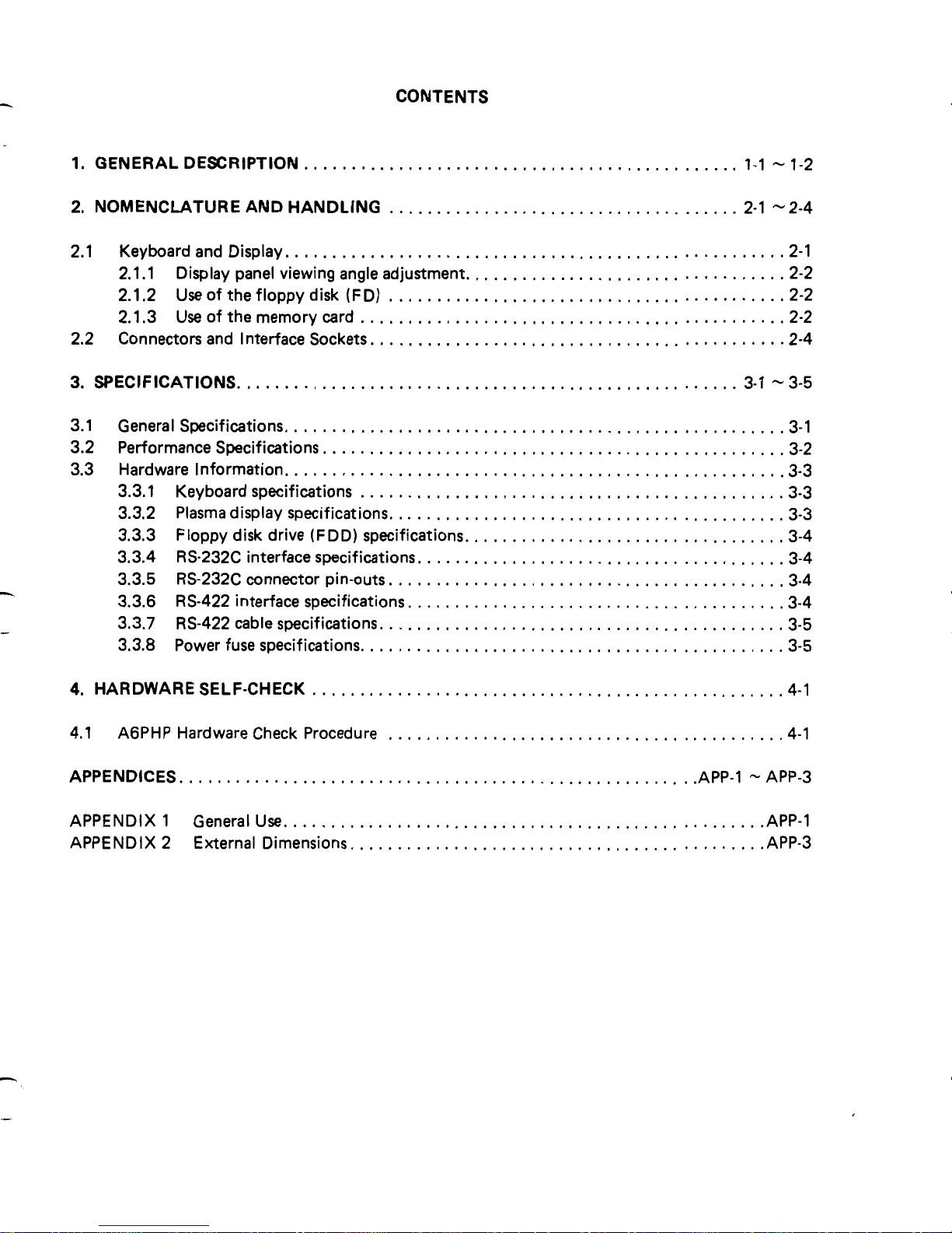
CONTENTS
.
1
.
GENERAL DESCRIPTION
..............................................
1-1 -1-2
2
.
NOMENCLATURE AND HANDLING
.....................................
2-1 -2-4
2.1 Keyboard and Display
....................................................
-2-1
2.1.1 Display panel viewing angle adjustment
..................................
2-2
2.1.2
Use
of the floppy disk (FD)
..........................................
2-2
2.1.3
Use
of the memory card
.............................................
2-2
2.2 Connectors and Interface Sockets
............................................
2-4
3
.
SPECIFICATIONS
.....................................................
3-1 -3-5
3.1 General Specifications
.....................................................
3-1
3.2 Performance Specifications.
................................................
3.2
3.3 Hardware Information
.....................................................
3.3
3.3.1 Keyboard specifications
.............................................
3-3
3.3.2 Plasma display specifications
..........................................
3-3
3.3.3 Floppy disk drive (FDD) specifications
..................................
3-4
3.3.4 RS-232C interface specifications
.......................................
3-4
3.3.5 RS-232C connector pin-outs
.........................................
-3-4
3.3.6 RS-422 interface specifications
........................................
3-4
3.3.7 RS-422 cable specifications
...........................................
3.5
3.3.8 Power fuse specifications
.............................................
3-5
4
.
HARDWARE SELF-CHECK
..................................................
4-1
4.1 A6PHP Hardware Check Procedure
..........................................
4-1
......................................................
APPENDICES
.AP P-1
-
APP-3
APPENDIX 1
General
Use
..................................................
.AP P-1
APPENDIX 2
External Dimensions
...........................................
.AP P.3
Page 4
1.
GENERAL DESCRIPTION
1.
GENERAL DESCRIPTION
The AGPHPE handy graphic programmer (referred to
as
"AGPHP")
is
a
peripheral unit for use with MELSEC-A and
K
series
PCs.
It
is
based on a 16-bit microprocessor and features many useful functions
as
well
as
ease
of operation. This Manual describes the AGPHP
hardware.
For
operating instructions, consult the relevant operating
manual for the system being used.
AGPHP features:
1)
Light weight and portable.
2)
The plasma display (referred to
as
"PDP'')
is
clear under a bright
3) The PDP screen allows easy program writing and correcting.
4)
A built-in 3.5-inch floppy disk drive (referred to
as
"FDD") for
program storage.
5) The operating systems for A and
K
series programmable control-
lers are stored on separate disks allowing
great
flexibility.
6)
The RS-232C port allows the printing out of ladder and list
diagrams
as
well
as
cross reference lists,
etc.
7)
By
connecting the PHP to a ROM writer (AGWU) using the
RS-
422 cable, programs and comments can be stored onto ROM.
8)
The PHP system can be booted in approximately five seconds by
inserting the memory card into the built-in memory card interface.
light without flickering and distorting.
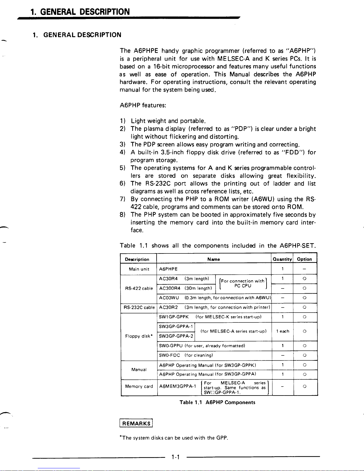
Table 1.1 shows all the components included in the AGPHP-SET.
J
Description
-
1
AGPHPE
Main unit
Option
Quantity
Name
ACOSWU (0.3m length, forconnection with AGWU)
0
1
SWlGP-GPPK (for MELSEC-K series start-up)
0
-
AC30R2 (3m length, for connection with printer)
RS-232C cable
0
-
SW3GP-GPPA-1
Floppy disk'
SW3GP-GPPA-2
~
0
1 each
(for MELSEC-A series start-up)
1
SWCLGPPU (for user, already formatted)
Ill0
I
GO-FDC
(for cleaning)
0
1 AGPHP Operating Manual (for SW3GP-GPPA)
0
1
AGPHP Operating Manual (for SW3GP-GPPK)
0
-
Manual
Table
1
.I
AGPHP
Components
[REMARKS]
*The system
disks
can
be
used
with the
GPP.
1-1
Page 5
1.
GENERAL
DESCRIPTION
Model
Cable
Voltage
(5016OHz
*2Hd
Dostination
W.
Germany
Sweden
Norway
(200-24OV)
1;
%
VD cable
Austria
A6PHPE-220VD
A6PHPE-240UK
AU cable
(200-240V)
1;
%
Australia
A6PHPE-240AU
UL cable
(100-12OV)
:
;;%
United
States
AGPHPE-115UL
UK cable
(200-24OV)
z
i;
%
Great Britain
AGPHPE-115UL
~~
Taiwan
UL cable
(100-12OV)
:
1;
%
AGPHPE-115UL
VD cable
(200-24OV)
1;
%
A6PHPE-220VD
UL cable
(100-120V)
:
;g%
Korea
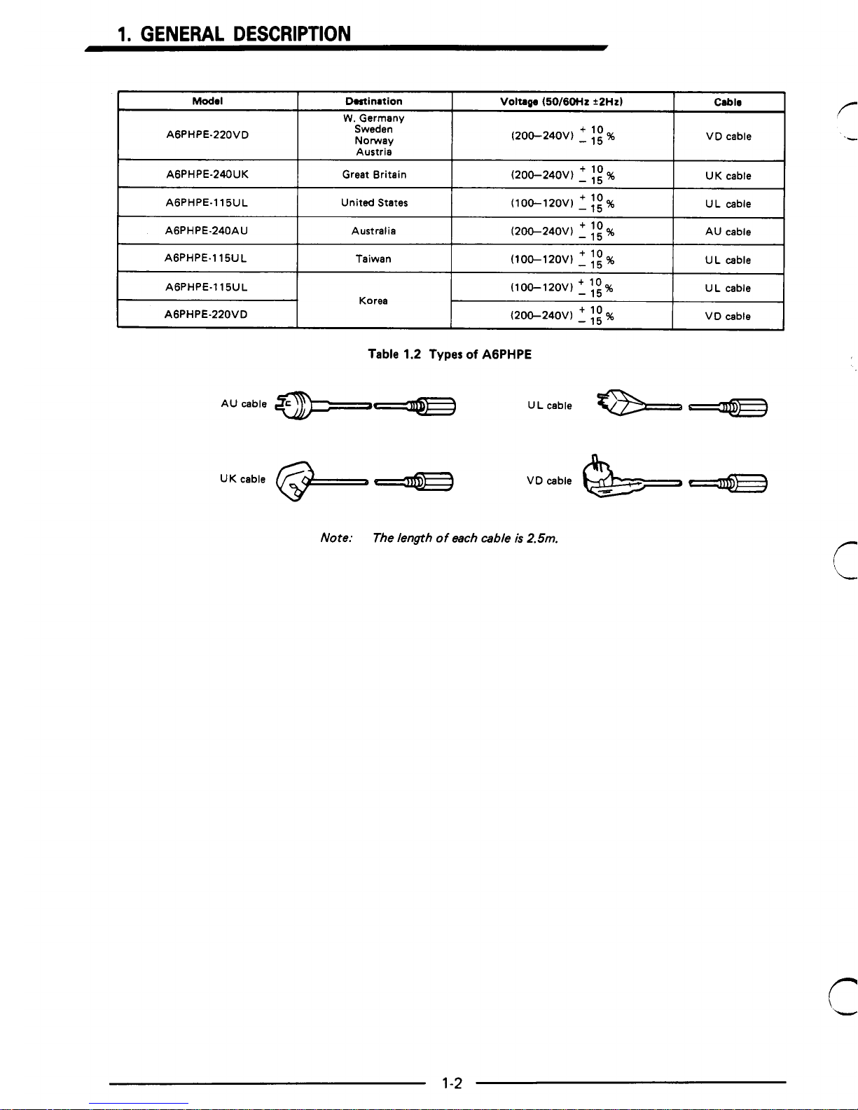
Table
1.2
Types
of
AGPHPE
AU cable
*--.--
U L cable
UK cable
e-
VD cable
Note:
The length
of
each cable
is
2.5m.
r-
L
1-2
Page 6
2.
NOMENCLATURE AND HANDLING
2.
NOMENCLATURE AND HANDLING
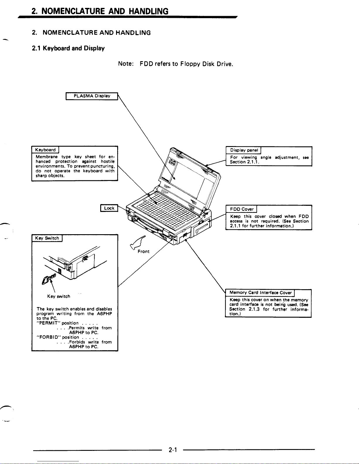
2.1
Keyboard and Display
4
Note: FDD refers to
Floppy
Disk Drive.
The key switch enables
and
disables
program writing from the AGPHP
. . .
.Permits write from
AGPHP to PC.
Page 7

2.
NOMENCLATURE AND HANDLING
2.1.1
Display panel viewing angle adjustment
r
The display panel
is
opened by sliding the two attache case style
locks and raising the lid. The viewing angle may be adjusted by
pushing the panel locking catch to the right.
Before closing the display panel, push the panel locking latch to the
right.
Handle the display panel with care to prevent damage to the Plasma
display. Ensure that the display
is
locked in position during use.
L
I
. ..
I
1
2.1.2
Use of the floppy disk (FD)
Open the FDD cover by pressing the catch in the direction indicated
by the arrow. Insert the FD with the arrow facing upwards,
To remove the FD, press the eject button.
FD (floppy
disk)
2.1.3
Use of the memory card
Remove the memory card interface cover by pressing the latch.
Insert the memory card
as
indicated in the diagram below.
Always replace the protective cover when
access
to the memory card
is
not required.
I
Memory card
L
2-2
Page 8

2.
NOMENCLATURE AND HANDLING
Latch
Memory card groove
I
Protection cover groove
Protection cover
Page 9

2.
NOMENCLATURE AND HANDLING
2.2
Connectors and Interface
Sockets
L
Cover
1
&
Cover
The cover slides down for
access
to
the RS232C and RS422 interfaces.
I
RS-422 Interface
I
/
Release button
connector
I
RS-232C Interface
I
-232C interface
(1
The A6PHP RS232C connector
is
(2) Tighten fixing screws to 3.6 to
a
25pin D sub female.
'ower Supply Cable
1
L
II
Power fuse
(MF60NR-2A-05)
Power plug: depends on model purchased
a
(1
To remove the fuse holder, turn
it
counterclockwise.
2-4
Page 10

3.
SPECIFICATIONS
3.
SPECIFICATIONS
3.1
General Specifications
F==3
Operating ambient temperature
I
Storage ambient temperature
I
10°C to 40°C
-10°C to 45OC
I
Operating ambient humidity
I
10
to
90%
RH
(noncondensing)
I
W/O
1
Storage ambient humidity
~~
Vibration resistance
I
Shock resistance
I
Dielectric withstand voltage
10 to
90%
RH (noncondensing)
1
W/O
I
~
Jap
ind.
std.
1
Acceleration
I
I
I
ooerated I oDerated
I
w
I
10 to 55Hz I0.035mm 1 0.075mm
I
155 to 150Hzl 0.5G
I
1G
1
(109 x 3 times in
X,
Y,
and 2 directions)
I
w'o
Conforms to
JIS C 0912.
I
1500V AC for 1 minute across batch
of
w,o
AC external terminals and case
I
I
Insulation resistance
5MCt
or
larger by 500V insulation resistance
I
w,o
meter across batch of AC external terminals
I
~~
Grounding
I
I
Operating Environment
I
I
Cooling method
I
Allowable instantaneous power
failure time
Class 3 grounding.
W
W
No
corrosive
gases
and dust should
be
minimal.
Selfcooling
W
loms
W
r"""""""""'"""""""
;
Above specifications apply with
(W)
or
:
:
without
(W/O)
Floppy Disk installed
as
;
:
indicated.
I
I
L-.--..-..-..-..------------------J
Table
3.1
General Specifications
Page 11

3.2
Performance Specifications
7
Item
Performanca
Spdficstionr
Line voltage
Depends on type purchased,
see
Table
1.2
page 1-2. Frequency 50/60Hz+2Hz.
I
Current consumption
I
Maximum 2A
I
I
Internal memory capacity
I
1M byte WOK bytes available for user)
I
I
Display area
I
Plasma display
I
~
Graphic display
640
x
400 dots
I
Display displayed characters
Number of
80 characters
x
32 lines
I
I
I
I
I
Types of characters
I
Alphanumeric characters,
special characters/symbols
I
Keyboard
165 keys, key sheet type
GPP mode keyboard
*
MELSAP mode keyboard
,--
Floppy disk drive
I
o
Equipped with 3.5 inch floppy disk drive
o
Floppy disk
capacity
1M bytes'
l
0
Conforms to EIA.
RS-422
RS422
I/F
o
For connection with MELSEC-A or K series
o
For connection with A6WUE
programmable controller;
Interfaces
I
RS-232C I/F
I
o
Conforms to EIA. RS-232C
o
For printer
I
I
Memory card interface
For operating system memory card
External dimensions
~~~))
I
4.6(H) x 14.96(W) x 10.83(D)
117(H)
x
380(W) x 275(D)
I
t
I
I
Weight
Approx. 6.3
Approx. 12.6
I
I
I
I
I
Table
3.2
Performance Specifications
I
REMARKS
I
*:
640K
bytes (after formatting)
3-2
Page 12

3.
SPECIFICATIONS
3.3
Hardware Information
3.3.1
Keyboard specifications
I
Instruction keys1
Keyboard
:
Key sheet
type
Key sheet material
:
Polyurethane
Key arrangement
:
GPP
mode keys
-
86
keys
MELSAP
mode keys
-
79
keys
Key life
: 1 Million strokes
I
Table
3.3
Keyboard
3.3.2
PLASMA
specifications
Ground color Black
Dot
color Orange
Ell
E
1 1
Number
of
characters
1
80
characters
x
32
lines
I
I
Display
format
640
x
320
dots
~~
Table
3.4
Plasma Display Specifications
Page 13

3.3.3 Floppy disk drive (FDD) specifications
r
Item Double-Density Recording
Unformatted
,-
1
.OM
bytes
Formatted
640K
bytes
Recording capacity
4
Application
I
o
For A6PHP operating system
o
Program storage
etc.
Table 3.5
Floppy
Disk Drive (FDD) Specifications
3.3.4 RS-232C interface specifications
1
Item Specifiution
1
I
For connection with
1
Printer with RS232C interface
I
I
Transmission mode
I
Conforms to EIA. RS-232C
1
I
Synchronous mode
I
Asynchronous mode
1
I
USART mode setting
I
Set
in printer mode
I
Connector
Table 3.6 RS-232C Interface Specifications
25-pin D-sub(fema1e) screw fixing type
3.3.5 RS-232C connector pin-outs
Pin Arranwmmt
I
Pin
I
sigml
I
AGPHP
I
General
Direction
Number
Symbol
+,outride
1
Transmit data
+
SD
2
Frame ground
FG
3 Receive data
c
RD
RTS
CTS
Request to send
-t
Signal ground
SG
7
Data set ready
c
DSR 6
Clear
to
send
t
20
DTR
-+
Data terminal ready
00000.000000
Table 3.7 RS-232C Connector Pin-Outs
3.3.6 RS-422 interface specifications
Item
Spuification
1
I
For connection with
o
MELSEC-A or K series programmable controllers
I
o
AGWUE
(ROM
writer)
I
I
Transmission mode
I
Conforms to EIA. RS-422
I
I
Synchronousmode
I
Asynchronous mode
I
I
Transmission speed
1
9600
BPS
I
USART mode setting
Automatically
set
by
OS
Connection cable
AC30R4, AC300R4, ACO3WU
Table 3.8 RS422 Interface Specifications
3-4
Page 14

3.
SPECIFICATIONS
3.3.7
RS-422
cable specifications
Item
Specification
AC3QR4
!
AC300R4
I
AC03WU
I
Connected units For connecting A or K series PC
For connecting
I
AGWU
I
Dielectric withstand voltage
I
500V AC for 1 minute
1
~~
Length m (inch)
0.13 (0.29) 5
(11)
0.5
(1.1)
Weight kg
(Ibs.)
0.3 (1 1 .E)
30
(1
181
1
3 (118)
Table
3.9
RS422
Cable Specifications
3.3.8
Power
fuse specifications
._
6.4 (0.25)
Itm
Specification
MF60NR-2A
05
Type
[
2A current rating
]
cartridge fuse,
250V
AC
rating,
0
Standard
JIS
C
6575 (Class
B)
Unit
:
mm
(inch)
Table
3.10
Power
Fuse
Specifications
Page 15

4.
HARDWARE SELF-CHECK
4.
HARDWARE SELF-CHECK
,r
A
hardware self-check can be executed by powering up the
PHP
without a system
FD
installed.
4.1
AGPHPE Hardware Check Procedure
'1
Power-on
I
1
Selfcheck
No,
hardware error
I
i?
Hardware check
I
I
Turn off the
POWER
switch.
I
I
I
Press key and turn on the
POWER switch.
LA
BOOT
check
"1
AR",
"2AR"
displayed
No
CRT
display
e
Faulty unit
I
REMARKS
]
Boot
check error messages are as follows:
(a) "2AR"
. . . . .
.
.FDD
fault
(b)
No
display
.
. . .
.AGPHP hardware fault
(1)
The message
"BOOT
ERROR" indicates a hardware fault.
Please return the PHP
to
the
sales representative.
-
4-
1
Page 16

4
APPENDICES
APPENDICES
APPENDIX
1
General
Use
,
Do
not subject the unit to high tempera-
ture or humidity.
Operating ambient temperature:
10°C to 40°C
'
Storage ambient temperature:
-1OOC to 45OC
Operatinghtorage humidity:
10 to
90%
RH
Prevent foreign objects from entering the
AGPHP and ensure that the keysheet
is
clear before closing display panel.
I
I
Protect the unit (particularly the Plasma
display) and
FDs
from magnetic fields.
1-1
Do
not submit the unit to impact.
Page 17

APPENDICES
-
Do
not use any solvents to clean the unit.
Protect the unit and
FD
from static
electricity.
-1
Do
not operate the unit in the vicinity of
a
APP-2
Page 18

APPENDICES
~~~
APPENDIX 2 External Dimensions
275
(10.83)
!Y
Unit
:
mm
(inch)
Fig. 1 Door
Closed
L
360 (14.17)
I
Unit
:
mm
(inch)
Fig.
2
Door
Open
Page 19

IMPORTANT
1
The components on
the
printed circuit boards will
be
damaged by
static
electricity,
so
avoid
handling them directly. If
it
is
necessary to handle them take the following precautions.
(1)
Ground human body and work bench.
(2)
Do
not touch the conductive areas
of
the printed circuit board and
its
electrical parts
with any non-grounded tools
etc.
Under no circumstances will Mitsubishi Electric be liable or responsible for any consequential damage that
may arise
as a result of the installation or use of this equipment.
All examples and diagrams shown in this manual are intended only
as
an aid to understanding the
text,
not
to guarantee operation. Mitsubishi Electric will accept no responsibility for actual use
of
the product based
on these illustrative examples.
Owing to the very great variety in possible applications of this equipment,
you
must satisty yourself
as
to
its suitability for your specific application.
Page 20

 Loading...