


U-ENM00043, REV 0
UNINTERRUPTIBLE POWER SUPPLY SYSTEM
MODEL
9900CX SERIES
OWNER’S / TECHNICAL MANUAL
(Inclusive Parallel Operation System Application)
UNINTERRUPTED
®
Peace of Mind

Preface
Revision A04/04/2017
4GBA0114

9900CX SERIES UPS
OWNERS / TECHNICAL MANUAL
Page Number:
i
TABLE OF CO NTENTS
LIST OF TABLES ............................................................................................................... ii
LIST OF FIGURES ............................................................................................................. iii
HOW TO USE THIS MANUAL ........................................................................................... iv
1.0 INTRODUCTION
....................................................................................................... 1-1
1.1 SAFETY PRECAUTION ............................................................................................ 1-2
1.2 GENERAL .................................................................................................................. 1-6
1.3 DEFINITIONS ............................................................................................................ 1-7
1.4 OPERATION OVERVIEW ......................................................................................... 1-8
1.5 SPECIFICATIONS ..................................................................................................... 1-15
2.0 OPERATION CONTROLS AND INDICATORS
....................................................... 2-1
2.1 LED DISPLAY ........................................................................................................... 2-2
2.2 EPO BUTTON ........................................................................................................... 2-2
2.3 LIQUID CRYSTAL DISPLAY ..................................................................................... 2-3
2.4 EXTERNAL SIGNAL TERMINAL BLOCK ................................................................. 2-8
2.5 EXTERNAL COMMUNICATION CONNECTOR ....................................................... 2-15
3.0 INSTALLATION AND OPERATION
......................................................................... 3-1
3.1 TRANSPORTATION AND INSTALLATION .............................................................. 3-1
3.2 INSTALLATION PROCEDURE ................................................................................. 3-1
3.3 PROCEDURE FOR CABLE CONNECTIONS .......................................................... 3-2
3.4 OPERATING PROCEDURES ................................................................................... 3-8
4.0 RESPONSE TO UPS FAILURE
............................................................................... 4-1
5.0 PARTS REPLACEMENT
.......................................................................................... 5-1
6.0 FAULT CODES
......................................................................................................... 6-1
7.0 WARRA NTY & OUT OF WARRANTY SERVICE
.................................................... 7-1
MITSUBISHI ELECTRIC 9900CX SERIES UPS

9900CX SERIES UPS
OWNERS / TECHNICAL MANUAL
Page Number:
ii
LIST OF TABLES
Table 1.1 UPS Installation Environment ..................................................................... 1-4
Table 1.2 Rating of Bypass Input Circuit Brea ker ..................................................... 1-5
Table 1.3 Power Specifications ................................................................................... 1-15
Table 1.4 UPS Cabinet Information............................................................................. 1-15
Table 1.5 Detail of Specifications ................................................................................ 1-16
Table 1.6 Rating of Contactors, Breakers and Fuses ................................................. 1-17
Table 2.1 Selectable Items for Output Contacts ......................................................... 2-11
Table 2.2 Selectable Items for Input Contacts ............................................................ 2-14
Table 3.1 How to Transport and Install the System .................................................... 3-1
Table 3.2 List of UPS Weights .................................................................................... 3-1
Table 3.3 Maximum Permitted Fault Current .............................................................. 3-2
Table 3.4 Recommended Cable Sizes ........................................................................ 3-4
Table 3.5 Recommended Hardware ........................................................................... 3-4
Table 3.6 Crimp Type Compression Lug .................................................................... 3-5
Table 6.1 Bypass Module Fault Code List .................................................................. 6-2
Table 6.2 UPS Module Fault Code List ....................................................................... 6-6
MITSUBISHI ELECTRIC 9900CX SERIES UPS

9900CX SERIES UPS
OWNERS / TECHNICAL MANUAL
Page Number:
iii
LIST OF FIGURES
Figure 1.1 Single Line Diagram-
Normal Operation: Load powered by UPS inverter ................................. 1-8
Figure 1.2 Single Line Diagram-
Bypass Operation: Load Fed through static bypass line ................... ...... 1-10
Figure 1.3 Single Line Diagram-Battery Operation ................................................... 1-11
Figure 1.4 UPS Parts Location .................................................................................. 1-13
Figure 2.1 Operation/Display Panel ........................................................................... 2-1
Figure 2.2 Main Screen ............................................................................................. 2-3
Figure 2.3(a) Start/Stop Operation ................................................................................. 2-4
Figure 2.3(b) Start Operation ......................................................................................... 2-4
Figure 2.3(c) Stop Operation ......................................................................................... 2-4
Figure 2.4(a) Input Values .............................................................................................. 2-4
Figure 2.4(b) Output Values ........................................................................................... 2-4
Figure 2.5 Remote/Local Operation or Date & Time Adjustment Select .................. 2-5
Figure 2.6(a) Log Menu .................................................................................................. 2-5
Figure 2.6(b) Event Log ................................................................................................. 2-5
Figure 2.6(c) Battery Log ............................................................................................... 2-5
Figure 2.7(a) Main Screen (Battery Operation) ............................................................. 2-6
Figure 2.7(b) Measurement Screen (Battery Operation) ............................................... 2-6
Figure 2.8 Main Screen (Fault Indication) ................................................................. 2-7
Figure 2.9 Message Screen ...................................................................................... 2-7
Figure 2.10(a)
Figure 2.10(b)
External Signal Terminal Block TN21-25 (NEC Class2)
External Signal Terminal Block TN11-14 (NEC Class2)
............................ 2-8
............................ 2-9
Figure 2.11 Control Wiring for External Contacts ........................................................ 2-10
Figure 2.12 Remote "Start" Contact Connections ....................................................... 2-12
Figure 2.13 External Communication Connector ........................................................ 2-15
Figure 3.1 UPS Terminal Designation ..................................................................... 3-5
Figure 3.2 Diagram of Input/Output Bus Bars and Terminal Blocks ....................... 3-6
Figure 3.3 Diagram of Power Wire and Control Wire Interconnection between
UPS and Battery ..................................................................................... 3-7
MITSUBISHI ELECTRIC 9900CX SERIES UPS
9900CX SERIES UPS
OWNERS / TECHNICAL MANUAL
Page Number:
iv
HOW TO USE THIS MANUAL
This manual is designed for ease of use, giving the user easy and quick reference to
information.
This manual uses notice icons to draw attention to the user important information regarding the
safe operation and installation of the UPS. The notice icons used in this manual are explained
below, and should be taken into account and adhered to whenever they appear in the text of
this manual.
Warning:
the user and service personnel against hazards and/or possible equipment
damage.
Caution:
the user and service personnel against possible equipment damage.
Note:
information regarding the UPS op eration, load status and display status.
Such information is essential if Mitsubishi field service grou p ass ist anc e and
correspondence is required.
Safety Recommendations:
Mitsubishi field service group assistance and correspondence is recommended.
A warning notice icon conveys information provided to protect
A caution notice icon conveys information prov ided to prote ct
A Note notice icon indicates when the user shoul d make a reference of
If any problems are encountered while following this manual,
MITSUBISHI ELECTRIC 9900CX SERIES UPS
9900CX SERIES UPS
OWNERS / TECHNICAL MANUAL
Page Number:
1-1
1.0 INTRODUCTION
The Mitsubishi Uni nterr upt ible Po wer S uppl y S ystem (UPS) is desi gne d to provi de many years
of reliable protection from power failure, brown-outs, line noise, and voltage transients. To
ensure optimum performance of the equipment, follow the manufacturer's instructions. This
manual contains des criptions required to operate the UPS. Ple ase read this manual c arefully
and retain it for future reference.
IMPORTANT SAFETY INSTRUCTIONS
SAVE THESE INSTRUCTIONS
This manual contains important instructions for the 9900CX SERIES Uninterruptible Power
Supply System that should be followed during installation and maintenance of the UPS and
batteries.
Lethal voltages exist within the equipment during operation. Observe all
warning and cautions in this manual. Failure to compl y may result in serious
injury or death. Obtain qualified service for this equipment as instructed.
WARNING 1
MITSUBISHI ELECTRIC 9900CX SERIES UPS
9900CX SERIES UPS
OWNERS / TECHNICAL MANUAL
1.1 SAFETY PRECAUTIONS
In order to maintain safety and perform start-up and maintenance of the UPS system
successfully, certified service personnel familiar w ith the operation of this equipment must
be involved. The following safety practices should always be followed.
PRECAUTIONS DURING INSTALLATION
Do not block the venti lation ports. The ventilation p orts should be arranged so that walls or
ceilings do not block ventila tion. (Mainte nance s paces des cribed in the c atalogu e or exter nal
drawings should be followed.)
If a ventilation port is blocked, the internal temperature of the UPS will rise, and consequently ,
a fire may be caused due to liquid leakage from batteries, short-circuits, or parts deterioration.
PRECAUTIONS FOR WIRING
WARNING 2
CAUTION
Page Number:
1-2
CAUTION
Ask professional agents for wiring work. Inappropriate wiring work may cause electric
shocks, injuries, or fire.
PRECAUTIONS TO PROFESSIONAL AGENTS
CAUTION
Use wiring conduit, pits or racks for input/output wiring. Inadvertent wiring may cause
injuries.
Use terminals for connection to the input/output terminals. Inadvertent connection may
cause electric shocks.
Do not drop dust or any other thing from the fan hole.
PRECAUTIONS FOR UPS OR UPS PARTS DISPOSAL
CAUTION
Since the UPS contain s pecial industrial waste, such as capacitors, insulators or batter ies,
they cannot be dis posed of l ike other gen eral wast e. Please c heck the disposal gui deline of
your district, contact the specialized contractor for disposal.
MITSUBISHI ELECTRIC 9900CX SERIES UPS
9900CX SERIES UPS
OWNERS / TECHNICAL MANUAL
Page Number:
1-3
PRECAUTIONS REGARDING BATTERIES
Before operating the system, carefully read the battery and battery cabinet operating manuals.
CAUTION
Follow the directions belo w when using the batteries , otherwise liquid l eakage, heat evolution,
and explosions may be caused.
a. Do not solder the batteries directly.
b. Do not charge the battery with its negative and positive terminals reversed.
c. Do not use different types or suppliers of batteries, or old and new batteries together.
d. Do not remove or damage the armoring tube of the battery.
e. Do not render a large impact or throw the battery.
f. Use wet clothes for cleaning the batter y. Do not use organic sol ven ts s uc h as gasoline and
thinner, or oil. Do not wipe the battery with cloths that c onta in or ganic so lvents or oil. K eep
the battery away from flexible vinyl materials.
g. Since the electric energy remains in the used batteries, treat them carefully to prevent
sparks and short circuits.
APPLICATION
CAUTION
If the UPS System is to be applied to support equipment that c ould affec t huma n safe ty, the
following steps must be adhered to:
1. Consult with Mitsubishi Electr ic Power Products Inc. UPS Division.
2. Special consideration of the overall back up power system configuration is required so that the
Mitsubishi UPS System is not the sole support required for operation, maintenance and
management of power availability. Other available power sources; for example utility,
emergency power generation or other systems shall also support power availability.
Definition of equipment that could affect human safety:
Life Support Systems (is a system whose failure to perform can be expected to result in
bodily injury or death.)
Essential Public Systems (is a system whose failure to perform can be expected to result
in bodily injury or death and/or property damage.)
MITSUBISHI ELECTRIC 9900CX SERIES UPS
Improper storage and installation environment may deteriorate insulation,
shorten component life and cause malfunctions.
Keep the installation environment per standard described as follows:
Table 1.1
9900CX SERIES UPS
OWNERS / TECHNICAL MANUAL
WARNING 3
The UPS is to be installed in a controlled environment.
UPS Installation Environment
Page Number:
1-4
No. Item Environment standard
1 Installation
Location
2 Ambient
temperature
3 Relative humidity The relative humidity must be held between 5 and 95%. There must be no
4 Altitude This equipment must not be applied at altitude that exceeds 1980m (6500ft)
5 Dust Dust in the room where the UPS is installed must not exceed normal
6 Inflammable gas
following
IEC654-4
Part 4
Indoors, without vibrations or impact
Minimum temperature: 32 F(0 C), Maximum temperature: 104 F(40 C) The
average temperature over any 24-hour period must be in the range 41
to 95
F(35 C).
condensation due to temperature changes.
above sea level.
atmospheric dust levels. In particular, that dust should not include iron particles,
oils or fats, or organic materials such as silicone.
There should be no inflammable/explosive gas.
Hydrogen sulfide (H2S) No more than 0.003 PPM
Sulfurous acid gas (SO2) No more than 0.01 PPM
Chlorine gas (Cl2) No more than 0.002 PPM
Ammonia gas (NH3) No more than 1 PPM
F (5 C)
Nitrous oxides (NOx) No more than 0.05 PPM
Ozone (O3) No more than 0.002 PPM
MITSUBISHI ELECTRIC 9900CX SERIES UPS
9900CX SERIES UPS
OWNERS / TECHNICAL MANUAL
Page Number:
1-5
WARNING 4
This UPS does not include a Bypass input circuit breaker (MCCB) to protect
bypass circuit. The Bypass input circuit breaker (MCCB) is to be field
supplied and installed. Recommended Break er (MCCB)'s Specifications are
as follows:
Table 1.2
Capacity (kVA) Bypass Voltage (Vac) Bypass Rating (Aac) Breaker (A)
Rating of Bypass Input Circuit Breaker
1050 480 1263 1600
1400 480 1684 2500
1750 480 2105 3000
2100 480 2526 4000
AC input and AC output overcurrent protection and disconnect devices shall be field
supplied and installed. The DC circuit breaker (MCCB) shall be field supplied and
installed. The overcurrent protection device should be installed in the Battery cabinet
and rated as indicated in Table 1.6.
MITSUBISHI ELECTRIC 9900CX SERIES UPS

9900CX SERIES UPS
OWNERS / TECHNICAL MANUAL
Page Number:
1-6
1.2 GENERAL
The Mitsubishi 9900CX SERIES UPS is designed t o provide continuous and clean electrica l
power to a critical load. Ad ditionall y the UPS monitors po wer conditions aff ecting the load. In
the event of an input power failure, the UPS will supply power to the critical load for the specified
battery time.
If the input power is not restored promptly, backup power from the U PS battery perm its the
orderly shutdown of equipment suppor ted by the UPS. The UP S is simple to st art-up, operate
and maintain.
The 9900CX SERIES UP S is avail able in 10 50, 1400, 1750, and 2100 k VA. Specif ications are
shown in Section 1.5.
This manual provides an overview of the 9900CX SERIES components and their functions. The
appearance and purpos e of operator contro ls and indicators is desc ribed with procedures for
operation, start-up, shutdown and basic maintenance included.
MITSUBISHI ELECTRIC 9900CX SERIES UPS

9900CX SERIES UPS
OWNERS / TECHNICAL MANUAL
Page Number:
1-7
1.3 DEFINITIONS
UNINTERRUPTIBLE POWER SUPPLY SYSTEM (UPS)
- All components within the UPS
Cabinet and associated ba tteries that function as a s ystem to provide cont inuous, conditioned
AC power to a load. This is sometimes referred to as the "System".
UPS CABINET
Bypass module, the 3
– The metal enclosur e which is the main part of UPS and composed of the
~
6 UPS modules, and the Cable Entry Section.
LINK CABINET
– The metal enclosure in which buses from UPS are connected.
UPS MODULE
- The metal encl osure which contains the Convert er / Inverter, Charger, and
internal control systems required to provide specified AC power to a load.
CONVERTER / INVERTER
- The UPS compone nts which c ontain th e equipm ent and controls
necessary to convert input AC power to output AC power required by the critical load.
CHARGER
- The UPS components which contain the equipment and controls necessary to
regulate DC power required for battery charging and for supplying power to the Inverter.
BYPASS MODULE
- The metal enclosure which contains the Bypass line, the Static transfer switch,
UPS operator controls, and internal control systems.
BYPASS LINE
- The line which conducts electricity directly from the input power source to the
critical load during Maintenance or whenever the UPS is not completely operational.
STATIC TRANSF ER SWIT CH
- The device whic h connects the critica l load to the b ypass lin e
when the Inverter cannot supply continuous power.
AC INPUT POWER
- Power provided b y the electrical utilit y company, or auxiliary generat or,
which is connected to the UPS for supplying the critical load.
BATTE R Y -
The rechargeable battery strings which supply DC power to the inverter to maintain
continuous AC power to the load during AC input power failure conditions.
MITSUBISHI ELECTRIC 9900CX SERIES UPS
9900CX SERIES UPS
OWNERS / TECHNICAL MANUAL
Page Number:
1-8
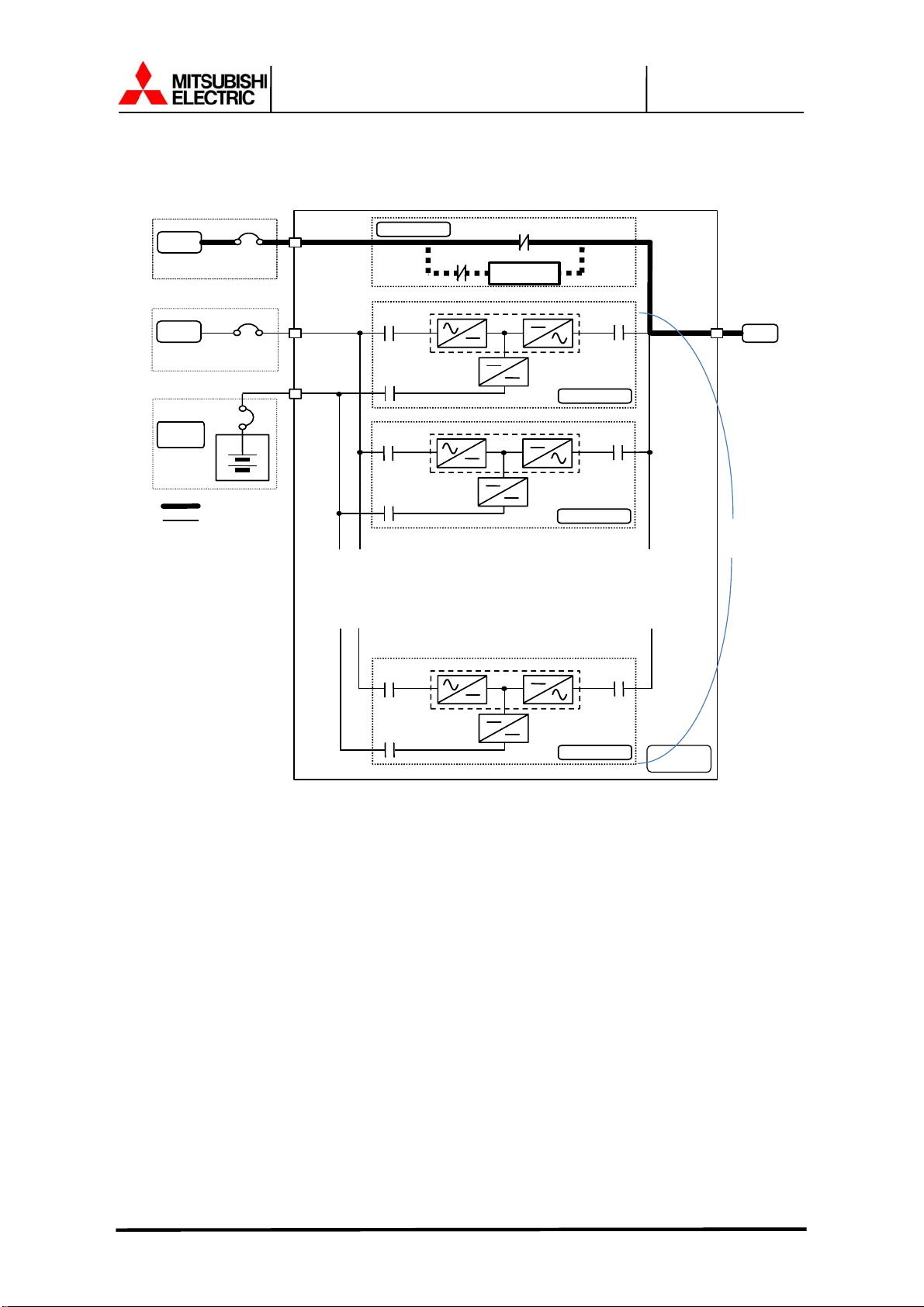
1.4 OPERATION OVERVIEW
The UPS provides two power paths between the utility source and the critical load.
Figure 1.1 shows the path for normal operation, with the load powered from the inverter. Figure
1.2 shows the path for bypass operation, with the load supplied through the static bypass line.
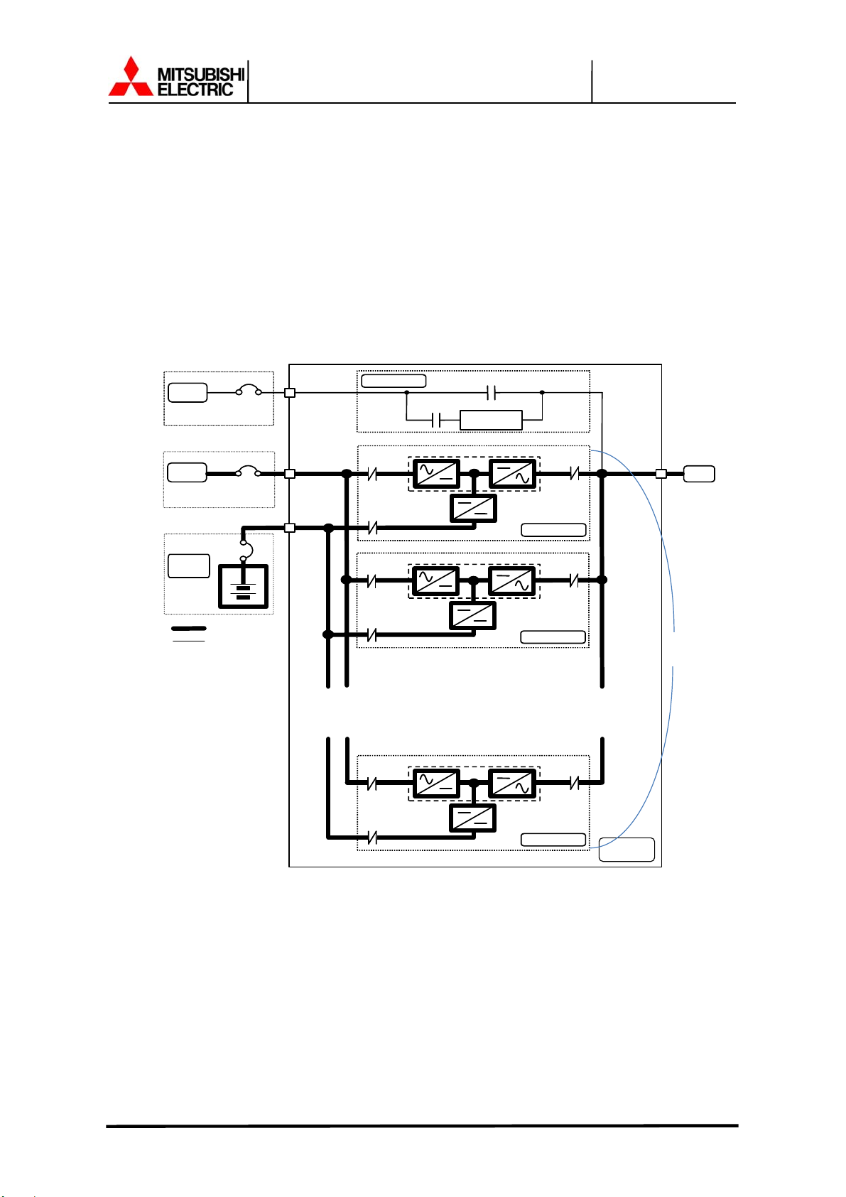
A) Normal operation:
Load power supplied by each system UPS inverter.
Figure 1.1
Single Line Diagram - Normal Operation: Load powered by UPS inverter
Bypass
Input
AC
input
Battery
Cabinet
External
BATTERY
Output
supplied
MCCB
User
supplied
MCCB
Power Flow
Not in Use
CB
CB
CB
Bypass Module
CB
1
CHARGER
CB2
CB
1
CHARGER
CB2
CB3
CONVERTER / INVERTER
CONVERTER / INVERTER
52S
Static Transfer
Switch
52C
UPS Module
52C
UPS Module
~
~
~
~
Output
3~6 UPS
modules
CB
CB2
1
CONVERTER / INVERTER
CHARGER
UPS Module
52C
UPS
CABINET
During normal operation, the path through the UPS inverters is used to power the load.
Referring to Figure 1.1: Input AC power is converted to DC by the Converter. DC power is
utilized to charge the U PS battery and to provide p ower to the Inverter. T he Inverter converts
the DC power to clean AC power to supply the critical load.
The conversion - inversio n process eliminates any vo ltage trans ients or f luctuat ions exist ing in
the input power before it reaches the critical load.
MITSUBISHI ELECTRIC 9900CX SERIES UPS
9900CX SERIES UPS
OWNERS / TECHNICAL MANUAL
The power drawn by the critical load is equally shared between all UPS whenever the system is
in the Parallel Operation.
Page Number:
1-9
In the event of a UPS module f ailure during Parallel O peration, the critical load po wer will be
continually supplied and shared by all other UPS.
The Bypass Input cir cuit break er (MCCB) for protection of the UPS and c ables are
field supplied and field installed. (See WARNING 4 on page 1-4).
MITSUBISHI ELECTRIC 9900CX SERIES UPS
B) Bypass Operation:
Figure 1.2
Bypass
Input
AC
input
Battery
Cabinet
External
BATTERY
Power Flow
Not in Use
Single Line Diagram - Bypass Operation: Load fed through static bypass line
CB
User
supplied
MCCB
CB
User
supplied
MCCB
CB
9900CX SERIES UPS
OWNERS / TECHNICAL MANUAL
Page Number:
1-10
Load Power supplied through UPS internal static bypass line.
Bypass Module
CB1
CHARGER
CB2
CB1
CHARGER
CB2
CB3
CONVERTER / INVERTER
CONVERTER / INVERTER
52S
Static T ra nsfer
Switch
52C
UPS Module
52C
UPS Module
~
~
~
~
Output
3~6 UPS
Modules
CB1
CB2
CONVERTER / INVERTER
CHARGER
UPS Module
52C
UPS
CABINET
Referring to Figure 1.2: The Internal Bypass line is a Hard-wired line through 52S which
supplies the critic al load wit h uncond itione d bypass inp ut po wer. Upo n switc hing t o the I nterna l
Bypass line, the Static Transfer Switch line through CB3 (herein after STS contactor CB3)
supplies the power immediately, and then the Interna l Bypass line through 52S supplies the
power. In the event of a switching to the Bypass line, the power to the critical load will be
uninterrupted. The purpose of this Internal Bypass line is to route power to the critical load while
the UPS module is de-energized (converter and inverter), and during Start-up before the system
is fully operational.
Each UPS internal static b ypass li ne will equal ly s hare the p ower s upp lied t o th e c ritic al l oad in
the Parallel Operatio n if a cable length of bypass line is equa l eac h other. For a MMS unabl e to
equalize the cable le ngth, additional rec tor s s houl d be installed to compensate the differ ence in
cable impedance.
MITSUBISHI ELECTRIC 9900CX SERIES UPS
9900CX SERIES UPS
OWNERS / TECHNICAL MANUAL
Page Number:
1-11
In the event of a load overcurrent, the UPS transfers to bypass without in te rruption to the crit ic al
load. In the case of the Parall el O p er ati on, all UPS will transf er to b ypass wit hout interruption to
the critical load.
The internal contro l system determines th e operation of the t wo paths, with the l oad powered
from the inverter being the normal operation.
C) Battery operation:
Load Power supplied by UPS batt ery.
Single Line Diagram - Battery Operation
Bypass Module
CB3
52S
Static Transfer
Switch
Bypass
Input
CB
supplied
MCCB
Figure 1.3
CONVERTER / INVERTER
CHARGER
CONVERTER / INVERTER
CHARGER
UPS Module
UPS Module
52C
Output
52C
3~6 UPS
AC
input
Battery
Cabinet
External
BATTERY
CB
User
supplied
MCCB
Power Flow
Not in Use
CB1
CB2
CB
CB1
CB2
modules
~
~
~
CB1
CB2
CONVERTER / INVERTER
CHARGER
UPS Module
52C
~
UPS
CABINET
Referring to Figure 1.3: In the event of AC input source failure or interruption, the UPS
Converter(s)* wil l de-energize and the UPS batter y(s)* will imm ediately discharg e and supply
DC power to the Inverter to maintain continuous AC power to the load. This operation will
continue until:
MITSUBISHI ELECTRIC 9900CX SERIES UPS

9900CX SERIES UPS
OWNERS / TECHNICAL MANUAL
Page Number:
1-12
a) The battery capacity expires and the inverter turns off, or
b) Input power is r estored after which the converter will power the inverter and cri tical load
and simultaneously recharge the batteries.
A fully charged battery will provide power for the specified time at the rated load, or longer, at a
reduced load.
(s)* : In the case of the Parallel Operation
When power is restored after a low battery shutdown, the UPS converter(s)* automatically
restarts operation, t he char ger(s) * recharges the batt eries and the In verter (s)* is automatic ally
restarted without op erator interv ention. Load is automatica lly assumed b y the inverter without
operator intervention.
(s)* : In the case of the Parallel Operation
The power drawn by the lo ad is equally shared between al l UPS regardless of the presence
or absence of the UPS tha t is (are) in batter y operation or not when ever the system is in the
Parallel Operation. .
MITSUBISHI ELECTRIC 9900CX SERIES UPS

Cable Entry
Section
9900CX SERIES UPS
OWNERS / TECHNICAL MANUAL
Figure 1.4
UPS Parts Location
Page Number:
1-13
1) UPS cabinet – Front View
Monitor Display
Bypass ModuleLCD Touch Panel
UPS Module
2) Backside of Bypass Module door
LCD Touch Panel
Monitor Display
Display PCB
DPAU-89
Main PCB
UPJR-D
MITSUBISHI ELECTRIC 9900CX SERIES UPS
 Loading...