

Mitsubishi Electric 900D-ID, DIS900D, CP900DW Operation Manual

PHOTO ID SYSTEM
900D-ID
[DIS900D+CP900DW(ID)]
OPERATION MANUAL
F
E
E
D
&
C
U
T
R
E
S
E
T
C
O
P
Y
SLD Security & Communications
The Old Forge, Ockham Lane, Ockham, Surrey GU23 6PH England
Phone +44.1483225633 · Fax +44.1483225634
sales@sld.co.uk · www.sld.co.uk
2
Page
1 SAFETY PRECAUTIONS ......................................................................................... 3 - 5
2 UNPACKING ................................................................................................................... 6
3 PRINTER SETUP ..................................................................................................... 7 - 9
4 CONNECTION ..............................................................................................................10
5 TAKING A PICTURE ..............................................................................................11 - 13
6 PICTURE QUALITY ADJUSTMENT ..................................................................... 14 - 19
7 FEATURES AND FUNCTIONS ............................................................................. 20 - 21
8 ADVANCED SETTING.......................................................................................... 22 - 31
9 TROUBLESHOOTING .......................................................................................... 32 - 34
10 SPECIFICATIONS ........................................................................................................ 35
This system complies with the requirements of the EC Directive 89/336/EEC "EMC Directive"
as amended by Directive 93/68/EEC.
The electro-magnetic susceptibility has been chosen at a level that gains proper operation in
residential areas, on business and light industrial premises and on small-scale enterprises,
inside as well as outside of the buildings. All places of operation are characterised by their
connection to the public low voltage power supply system.
CONTENTS
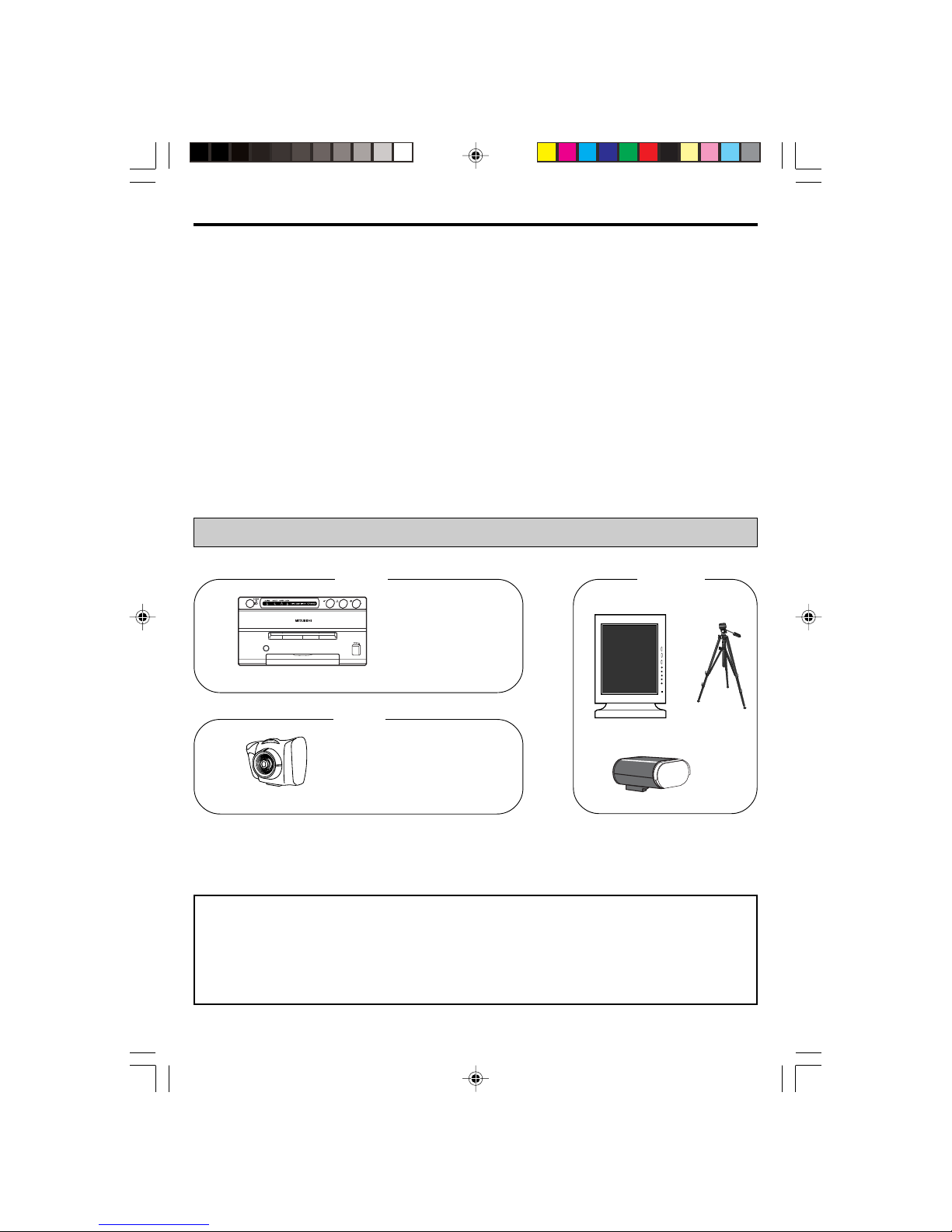
This system is composed by the following components.
CONTENTS
Camera
• System cable
• Operation manual
FEED&CUT
RESET
COPY
Printer
• AC cable
• Operation manual
• Ink cassette
• Printer driver
• Spacers
• Screws
Printer
Monitor
Tripod
Options
(not provided from Mitsubishi)
System
Flash

3
1. SAFETY PRECAUTIONS
In the interest of safety, please observe the following precautions:
POWER REQUIREMENT
This system is designed for operation on 120V AC or 220V-240V, 50/60Hz AC. Never connect to any outlet
or power supply having a different voltage or frequency.
WARNING: THIS APPARATUS MUST BE EARTHED.
AVERTISSEMENT: CET APPAREIL DOIT ETRE MIS A LA TERRE.
PROTECTIVE MEASURES
IF ABNORMALITIES ARISE, .....
Use of the unit during emission of smoke or abnormal sounds (without adopting countermeasures) is
dangerous. In such a case, unplug the power cord from the source outlet immediately, and request
maintenance service from the sales dealer.
NEVER INSERT ANY OBJECT INTO THE UNIT
Foreign objects of an kind inserted into this unit constitute a safety hazard and can cause extensive damage.
DO NOT PLACE ANYTHING ON THE DIGITAL COLOR PRINTER
Heavy objects placed on the Digital color printer can cause damage or obstruct proper ventilation.
PROTECT THE POWER CORD
Damage to the power cord may cause fire or shock hazard. When unplugging, hold by the plug only and
remove carefully.
DO NOT PLACE WATER CONTAINERS ON THE UNIT
Do not place flower vases, and other water-holding containers on the device. If, for some reason, water
seeps to the inside of the unit, unplug the power cord from the source outlet, and contact the sales dealer. If
used without corrective measures, the unit may be damaged.
"In the interest of safety, avoid handling of liquids near the unit."
DO NOT REMOVE THE CABINET
Touching internal parts is dangerous, and it may lead to malfunction. Contact the sales dealer to carry out
internal checks and adjustments. Before opening the cover to remove jammed paper, etc., be sure to
disconnect the power cord plug.
UNPLUG THE POWER CORD IF THE UNIT IS NOT IN USE
Turn off the MAIN power switch and unplug the power cord if the unit is not in use for extended periods.
WHEN TRANSPORTING THE UNIT
When transporting the unit, remove the sheet cartridge and paper from the paper cassette.
BE CAREFUL AROUND PRINT PAPER EXIT SLOT
Don't insert your hand or any material into the paper exit slot during printing.
Don't touch the cutter blade inside the paper exit slot as this can cause injury.
DO NOT TOUCH THE THERMAL HEAD
Do not touch the thermal head (located inside the unit).
The thermal head is heated to high temperature and may cause injury.

4
BE CAREFUL WITH THE PRINTING UNIT
Don't move the unit while the drawer is open. This may cause injury.
Be careful not to catch your finger in the printing unit while the drawer is being closed.
CONNECTION CABLES
Only use the cables provided.
INSTALLATION LOCATIONS
MAINTAIN GOOD VENTILATION
Ventilation slots and holes are provided on the top, sides and bottom of this unit. Place the unit on a hard
and level surface and locate at least 10 cm from walls to insure proper ventilation. When putting the unit on
the system rack, ensure there is a space between the unit and the back of the rack.
UNSUITABLE LOCATIONS
Avoid uneven surfaces or hot-springs areas where hydrogen sulfide and acidic ions are likely to be
generated.
PLACES WITH HIGH HUMIDITY AND DUST
Do not place the unit in locations with high humidity and dust. They can cause extensive damage. Avoid
places where unit is likely to be exposed to oily fumes and vapours.
PLACES LIKELY TO BE EXTREMELY HOT
Places exposed to direct sunlight, or near heating appliances can attain extremely high temperatures, which
may deform the cabinet, or cause other damage.
PLACE THE UNIT ON A HORIZONTAL SURFACE
The unit is likely to be affected if it is placed in slanted conditions or in unstable places.
PROTECT AGAINST DEW FORMATION
In extremely cold regions, if the unit is moved quickly from an extremely cold place to warmer one, dew is
likely to be formed.
If dew is formed, printing is not possible.
OPERATING AMBIENT TEMPERATURE RANGE
The operating ambient temperature range is 5°C- 40°C, and humidity of 20-80%. When using the unit on the
system rack, be sure to keep this ambient temperature inside the rack.
FOR LONG OPERATING LIFE
UNSUITABLE MATERIALS FOR THE DIGITAL COLOR PRINTER
Coat flaking and deformation are likely to occur if the unit is wiped with chemical dusters, benzine, thinner or
any other solvent, if rubber or PVC items are left in contact with the unit for extended duration, or if the unit
is sprayed with insecticide.
CARE OF THE CABINET
Unplug and clean with a soft cloth slightly moistened with a mild soap and water solution. Allow to dry
completely before operating. Never use petroleum based solutions or abrasive cleaners.
HEAD ABRASION
The thermal head, like the video head, wears out. When it is abraded, it becomes hard to print out fine
details of the picture. In such a case, it is necessary to replace the thermal head. Consult with the sales
dealer for replacing the head.

5
CAUTION ON RELOCATING
When transporting this unit, make sure it is not likely to be subjected to impacts. They can be a prime cause
for damage. Also, make sure to disconnect the power cord from the power outlet, and all cables from the
devices.
CONNECTING DEVICES
Read thoroughly "Operating Precautions" of the instruction booklets for the devices connected with the
Digital color printer.
The power cord must be disconnected after printing is over.
OTHER CAUTIONS
Dust or other foreign matter adhering to the print paper or the sheet cartridge, or deformation resulting from
exposure to extremely low or high temperatures could cause loss of colour, uneven colour or lines, or
wrinkles in the print images.
NOTE:
YOUR UNDERSTANDING IS REQUESTED FOR THE LOSS OF IMAGES IN MEMORY DUE TO THE
SUDDEN OCCURRENCE OF A MALFUNCTION.
WHEN USING A COMPACT FLASH
TM
1.To use the Compact Flash,
1. Insert a Compact Flash into the camera.
2. Turn on the power.
To pull out a Compact Flash,
1. Turn off the power.
2. Pull out the Compact Flash.
2. When a Compact Flash is inserted or pulled out during power on status, the Compact Flash and the
camera may be damaged.
Make sure to turn off the power when inserting or pulling out the Compact Flash.
3. Compact Flashes recommended
Manufacturer : Mitsubishi, SanDisk, LEXAR
Capacity : 8M byte, 16M byte, 32M byte, 64M byte
• Compact Flash is a trademark of SanDisk Corporation.
The camera is turnd on
with a CF inserted
without a CF inserted
CF is available.
CF is not available.
* CF : Compact Flash
6
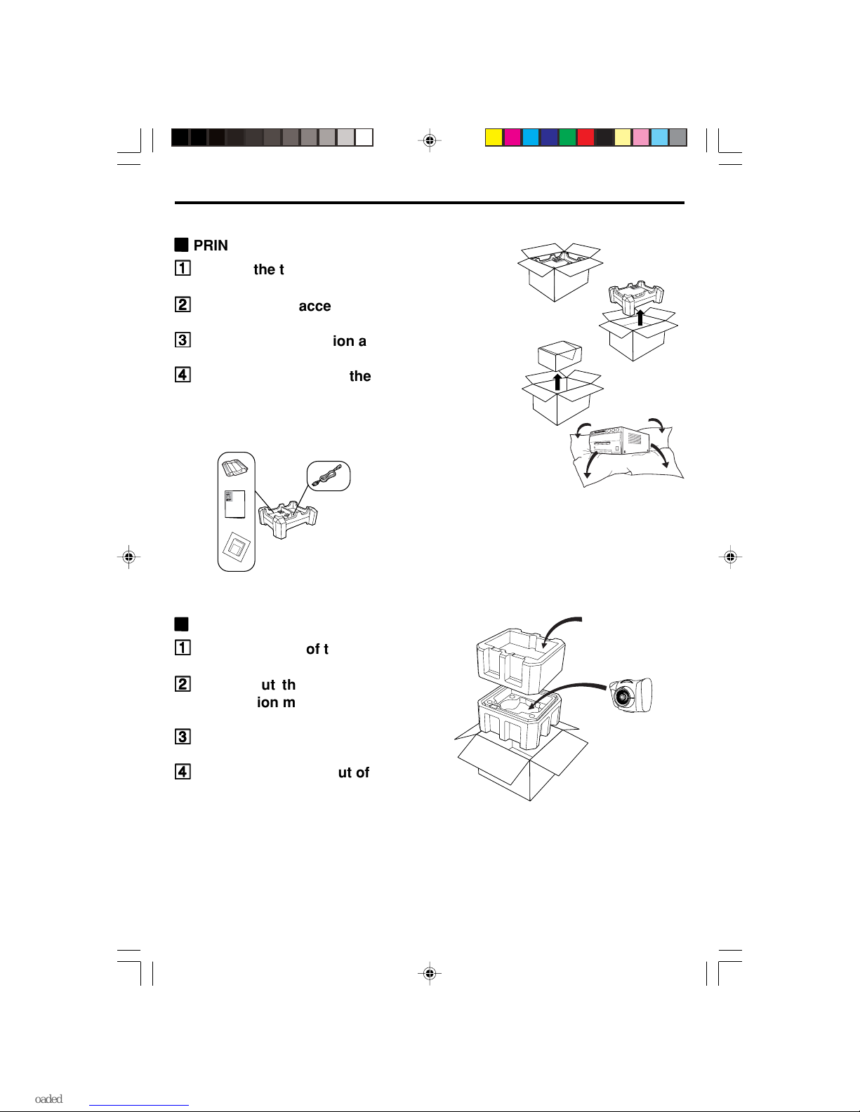
2. UNPACKING
Take the unit out of the box by the following procedures. Make sure to check the contents.
22
22
2
PRINTER
11
11
1
Open the top of the box.
22
22
2
Remove the accessory box.
33
33
3
Remove the cushion above the unit.
44
44
4
Take the unit out of the box carefully.
Make sure to keep the unit horizontal.
Then, unwrap the packing.
• Accessory box
DIGITAL
COLOR PRINTER
DI
G
I
T
A
L
C
O
L
O
R
P
R
IN
T
E
R
DIGITAL
COLOR PRINTER
Power cord
Ink cassette
Operation manual
Printer driver
F
RO
N
T
F
R
O
N
T
TOP
System cable
Operation manual
Camera
22
22
2
CAMERA, ETC.
11
11
1
Open the top of the box.
22
22
2
Take out the system cable and
operation manual.
33
33
3
Remove the top cushion.
44
44
4
Take the camera out of the box
carefully.
7
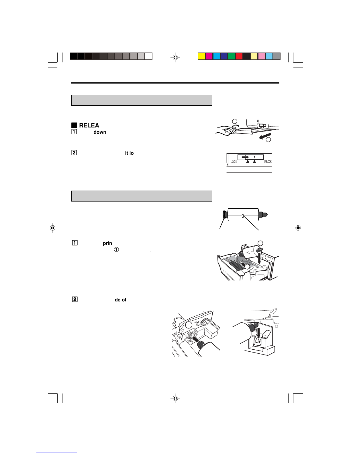
3. PRINTER SETUP
UNLOCK THE PRINTING UNIT
See CP900DW(ID) operation manual for details.
22
22
2
RELEASING THE PRINTING UNIT LOCK
11
11
1
Press down the knob to pull out the tray.
Before printing a photo, install print paper and ink cassette.
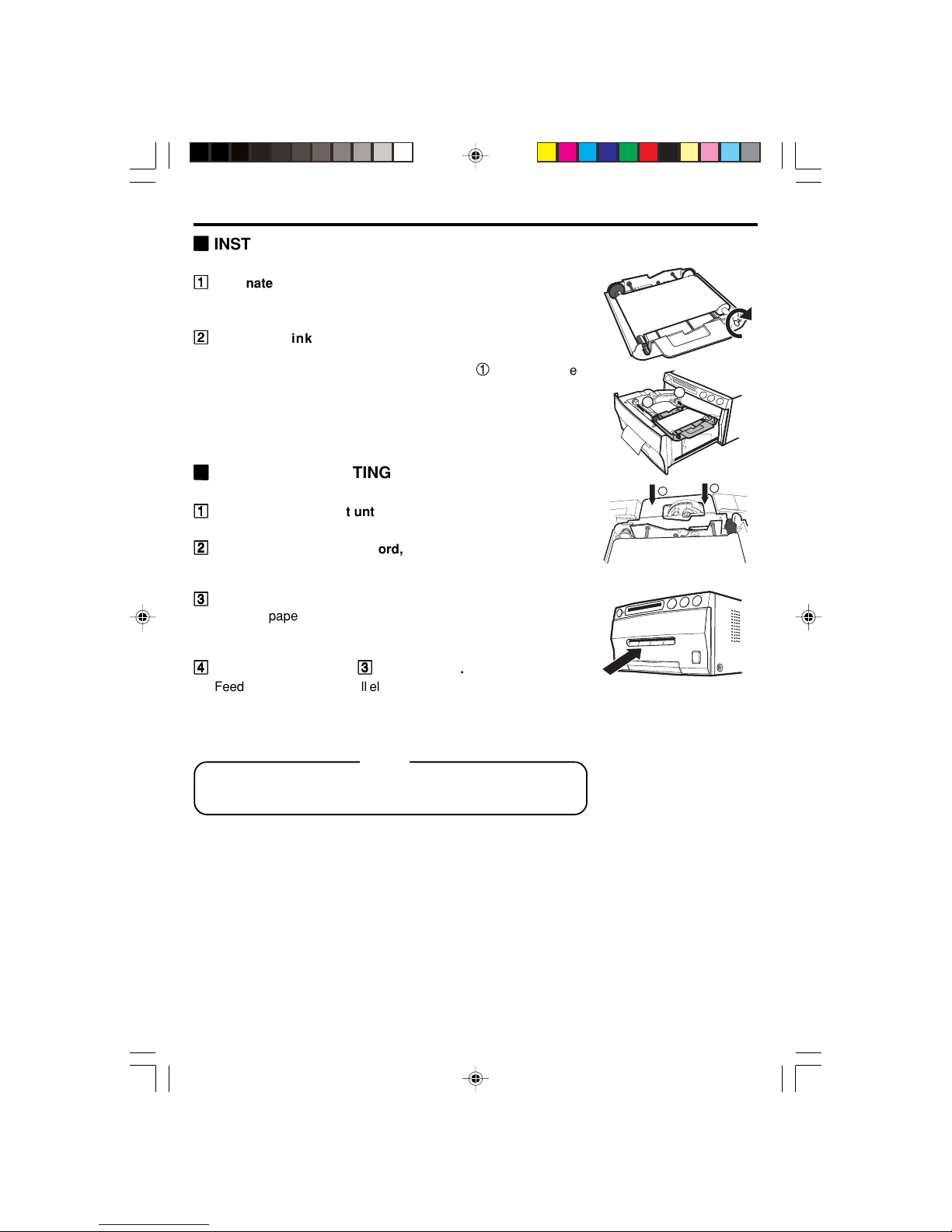
INSTALLING PRINT PAPER
Do not remove the seal on the print paper yet.
11
11
1
Insert the print paper roller with gear on the left.
Press the folder 1 as shown right, and set the print paper roller.
22
22
2
Set the other side of roller without gear.
1
2
22
22
2
Shift the printing unit lock switch to the right (UNLOCK).
2
1
1
Front side
Left side
Right side
Gear
Seal
8
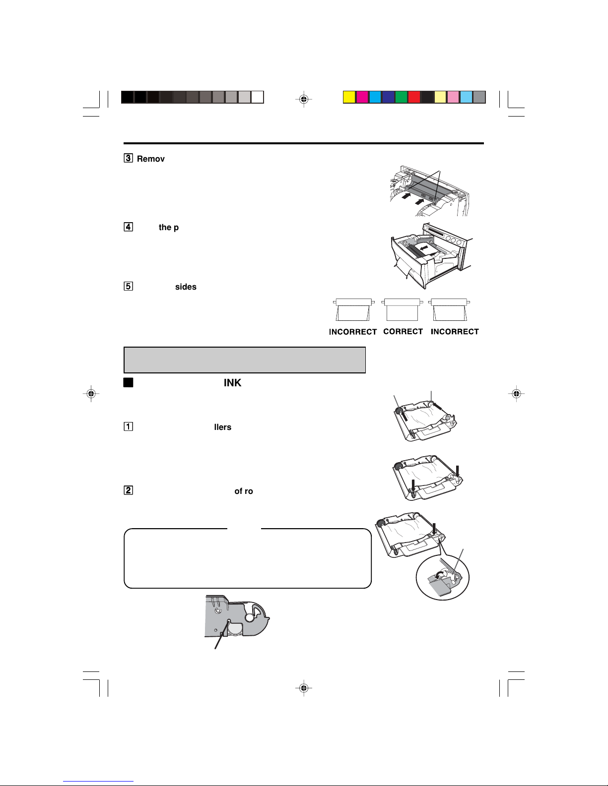
33
33
3
Remove the seal, and insert the edge of the print paper
right below the roller cover with arrow marks towards the
front panel.
Make sure to insert the paper straight.
44
44
4
Feed the print paper through the paper outlet by hand.
55
55
5
Pull both sides of the print paper to eliminate slack.
Paper
Paper
Paper
INSTALLATION OF INK SHEET
22
22
2
INSTALLING THE INK SHEET
Load the ink sheet into the cassette before inserting the cassette
into the printer.
11
11
1
Put the ink sheet rollers with flat tops into the holes of ink
cassette.
Put the white roller (rolled with ink sheet) to the ink cassette first.
Then, put the colored roller (without ink sheet) to the ink
cassette.
22
22
2
Position the other sides of rollers. Set IC at this time.
IC chip with the IC holder is attached to the ink sheet.
Set the IC holder to the ink cassette as shown right.
NOTE
• Do not remove the IC chip or IC holder from the ink sheet.
Removal of the IC will stop the printer from functioning
correctly.
• Set the projected part of the IC holder to the correct position
as shown below.
arrow marks
Projected part
colored roller
white roller
IC holder
9
22
22
2
INSTALLING THE INK CASSETTE
11
11
1
Eliminate any slack of the ink sheet.
Hold the colored roller and turn the white roller.
22
22
2
Insert the ink cassette with the ink sheet into its
compartment.
Put the ink cassette with flat top side to each 1. Then, set the
other side (with handle) as shown right. When exchanging the
ink sheet, remove the cassette by holding the handle.
22
22
2
INSERT THE PRINTING UNIT
11
11
1
Push the printing unit until it is locked into place.
22
22
2
After plugging the power cord, press POWER button on the
front panel.
33
33
3
Press FEED&CUT button.
The print paper is automatically cut after feeding about 10 cm (4
inches).
44
44
4
Repeat the above step
33
33
3
once or twice.
Feeding the print paper will eliminate fingerprints and dust during
handling. The printing unit is initialized.
NOTE
An IC is built in the ink sheet. This is the IC chip, not a battery.
This IC is safe to be thrown away with normal waste.
1
1
2
2
10
AC LINE
REMOTE
USB
OFF
ON
8 7 6 5 4 3 2 1
OPTION I/F
W
T
-
+
SET
EV
MULTI
COLOR
B/W
PRINT
S
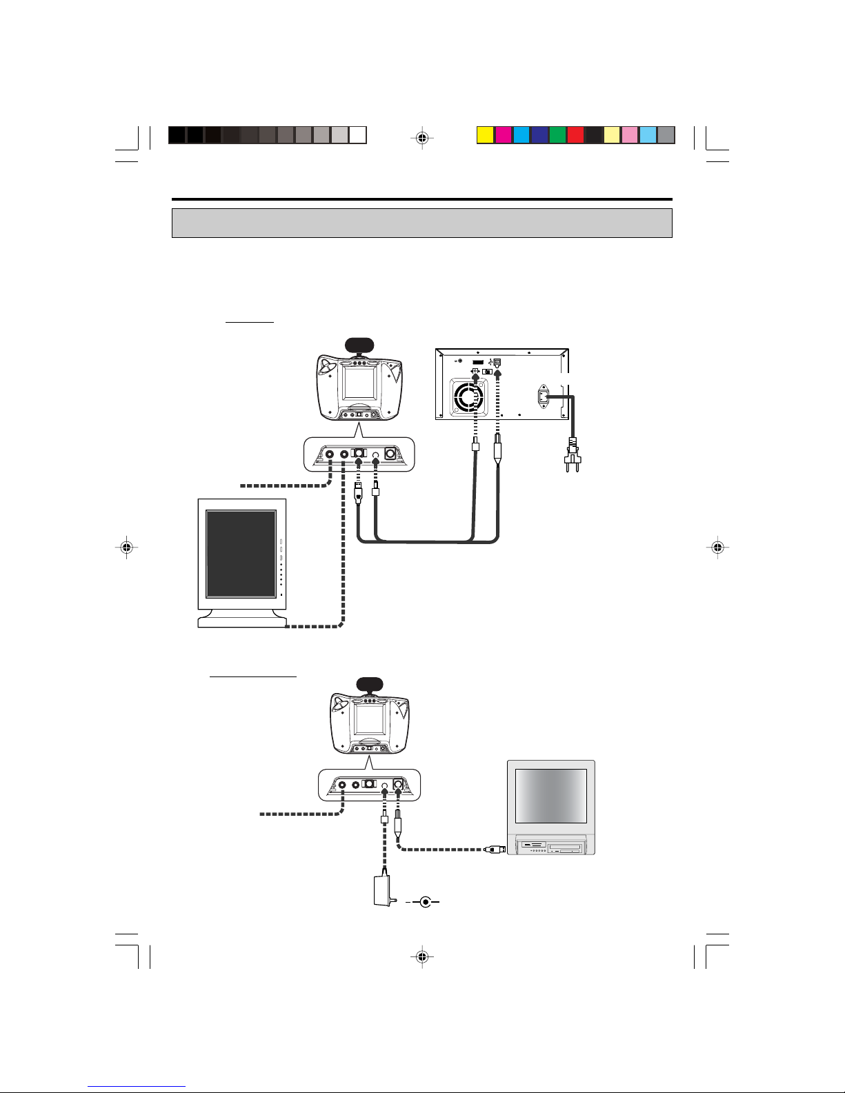
4. CONNECTION
Connect the components as follows.(example)
Make sure to turn off each device when connecting.
After connecting the cables, make sure to set the cover over the terminals on the camera.
(See page 21 for removing and setting the cover.)
CABLE CONNECTION
System cable
AC power
cord
(supplied
with the
printer)
Monitor (option)
Flash (option)
To AC LINE
To USB
To
OPTION I/F
External flash
(option)
900D-ID
DIS900D+DPS
W
T
-
+
SET
EV
MULTI
COLOR
B/W
PRINT
S
+
Flash (option)
DPS system
USB cable
External flash
(option)
12V 1A (Option)
11
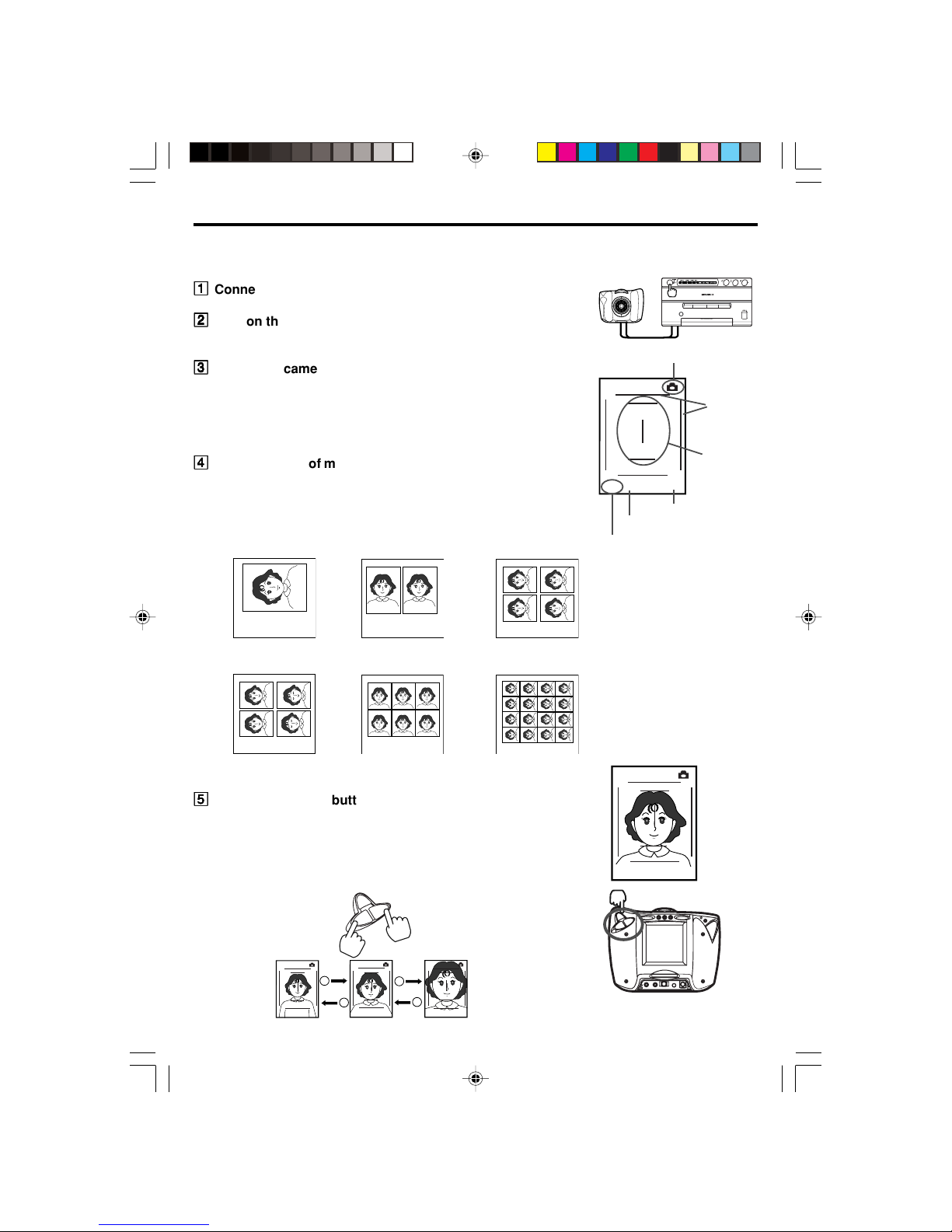
You can take up to four pictures (without Compact Flash), and choose
the best one.
11
11
1
Connect the camera and the printer.
22
22
2
Turn on the printer.
The camera is also turned on.
33
33
3
Switch the camera to CAMERA mode.
• When the camera is turned on, it is set to CAMERA mode.
• If PLAY mode is selected, press CAMERA/PLAY button.
• The printing area, face guide, multi format setting, color
setting and memory position are displayed.
44
44
4
Select the type of multiple picture (1, 2, 4, 4D, 6, 16 or 1L) by
MULTI button.
Each time the button is pressed, the format changes.
1 1-image (75x100mm) 2 2-image (50.8x74mm)
4,4D 4-image (36.5x48mm) 6 6-image (30x35mm)
16 16-image (19x25mm)
124
4D 6 16
55
55
5
Press T (+) or W (-) button to adjust the size to fit the face in
the face guide.
Adjust the position where:
• The face is positioned just within the upper and lower
horizonetal lines on the LCD.
• The nose is aligned with the vertical line at the center of
the LCD.
4D a n
T (+) T (+)
W (-) W (-)
W
T
-
+
SET
4Da n
4Da n
4Da n
5. TAKING A PICTURE
FEED&CUT
RESET
COPY
4D a n
CAMERA mode
Printing
area
Face
guide
W
T
-
+
SET
EV
MULTI
COLOR
B/W
PRINT
Multi format setting
Color setting
Memory position
 Loading...