


INVERTER
Plug-in option
FR-A8AR
INSTRUCTION MANUAL
Relay output function
PRE-OPERATION INSTRUCTIONS
INSTALLATION AND WIRING
RELAY OUTPUT
1
2
3
Thank you for choosing this Mitsubishi Electric inverter plug-in option.
WARNING
CAUTION
CAUTION
This Instruction Manual provides handling information and precautions for use of this product. Incorrect handling might cause an unexpected
fault. Before using this product, read all relevant instruction manuals carefully to ensure proper use.
Please forward this Instruction Manual to the end user.
Safety instructions
Do not attempt to install, operate, maintain or inspect this product until you have read this Instruction Manual and appended documents
carefully. Do not use this product until you have a full knowledge of this product mechanism, safety information and instructions. In this
Instruction Manual, the safety instruction levels are classified into "WARNING" and "CAUTION".
Incorrect handling may cause hazardous conditions, resulting in death or severe injury.
Incorrect handling may cause hazardous conditions, resulting in medium or slight injury, or may cause only
material damage.
Note that even the level may lead to a serious consequence depending on conditions. Be sure to follow the
instructions of both levels as they are critical to personnel safety.
Electric shock prevention
WARNING
Do not remove the front cover or the wiring cover of the inverter while the inverter power is ON. Do not operate the inverter with any cover or wiring cover removed,
as accidental contact with exposed high-voltage terminals and internal components may occur, resulting in an electrical shock.
Even if power is OFF, do not remove the front cover of the inverter except for wiring or periodic inspection as you may accidentally touch the charged circuits and
get an electric shock.
Before wiring or inspection, check that the display of the inverter operation panel is OFF. Any person who is involved in wiring or i nspec tion shall wait f or 10 minut es
or longer after power OFF and check that there are no residual voltage using a tester or the like. The capacitor is charged with high voltage for some time after
power OFF, and it is dangerous.
Any person who is involved in wiring or inspection of this product shall be fully competent to do the work.
This product must be installed before wiring. Otherwise you may get an electric shock or be injured.
Do not subject the cables to scratches, excessive stress, heavy loads or pinching. Doing so may cause an electric shock.
Do not touch this product or handle the cables with wet hands. Doing so may cause an electric shock.
Injury prevention
CAUTION
The voltage applied to each terminal must be as specified in the Instruction Manual. Otherwise a burst, damage, etc. may occur.
The cables must be connected to the correct terminals. Otherwise a burst, damage, etc. may occur.
The polarity (+ and -) must be correct. Otherwise a burst, damage, etc. may occur.
While power is ON or for some time after power OFF, do not touch the inverter as it will be extremely hot. Doing so may cause a burn.
2
Additional instructions
The following instructions must be also followed. If this product is handled incorrectly, it may cause unexpected fault, an injury, or an electric
shock.
CAUTION
Transportation and installation
Do not stand or place heavy objects on this product.
The installing orientation of this product must be correct.
Do not install or operate this product if it is damaged or has parts missing.
Foreign conductive objects must be prevented from entering the inverter. That includes screws and metal fragments or other flammable substance such as oil.
If halogen-based materials (fluorine, chlorine, bromine, iodine, etc.), included in fumigants to sterilize or disinfect wooden packages, infiltrate into this product, the
product may be damaged. Prevent residual fumigant components from being infiltrated into the product when packaging, or use an alternative sterilization or
disinfection method (heat disinfection, etc.). Note that sterilization or disinfection of wooden package should also be performed before packing the product.
Test operation
Before starting operation, confirm or adjust the parameter settings. Failure to do so may cause some machines to make unexpected motions.
WARNING
Usage
Do not modify this product.
Do not remove any part which is not instructed to be removed in the Instruction Manuals. Doing so may lead to a failure or damage of this product.
CAUTION
Usage
As all parameters return to their initial values after Parameter clear or All parameter clear is performed, the needed parameters for operation of the inverter and this
product must be set again before the operation is started.
To avoid damage to this product due to static electricity, static electricity in your body must be discharged before you touch this product.
Maintenance, inspection and parts replacement
Do not carry out a megger (insul ation resistance) test.
Disposal
This product must be treated as industrial waste.
For clarity purpose, illustrations in this Instruction Manual may be drawn with covers or safety guards removed. Ensure all covers and safety guards are properly
General instruction
installed prior to starting operation.
3

─ CONTENTS ─
1 PRE-OPERATION INSTRUCTIONS 5
1.1 Unpacking and checking the product.......................................................................................................5
1.1.1 Product confirmation....................................................................................................................................... 5
1.2 Component names .....................................................................................................................................6
1.3 Specifications .............................................................................................................................................7
2 INSTALLATION AND WIRING 8
2.1 Pre-installation instructions ......................................................................................................................8
2.2 Installation procedure ................................................................................................................................8
2.3 Wiring ........................................................................................................................................................11
3 RELAY OUTPUT 15
3.1 Internal block diagram .............................................................................................................................15
3.2 Terminals...................................................................................................................................................16
3.3 Parameter list............................................................................................................................................16
3.4 Parameter setting .....................................................................................................................................17
3.5 Connection diagram when using electronic bypass sequence function ............................................18
APPENDIX 19
Appendix1 Instructions for compliance with the EU Directives ..................................................................19
Appendix2 Instructions for EAC.....................................................................................................................20
Appendix3 Restricted Use of Hazardous Substances in Electronic and Electrical Products ..................21
Appendix4 Referenced Standard (Requirement of Chinese standardized law).........................................22
4
1 PRE-OPERATION INSTRUCTIONS
1.1 Unpacking and checking the product
Take the plug-in option out of the package, check the product name, and confirm that the product is as you ordered and intact.
The product is a plug-in made option made for the FR-A800/F800 series.
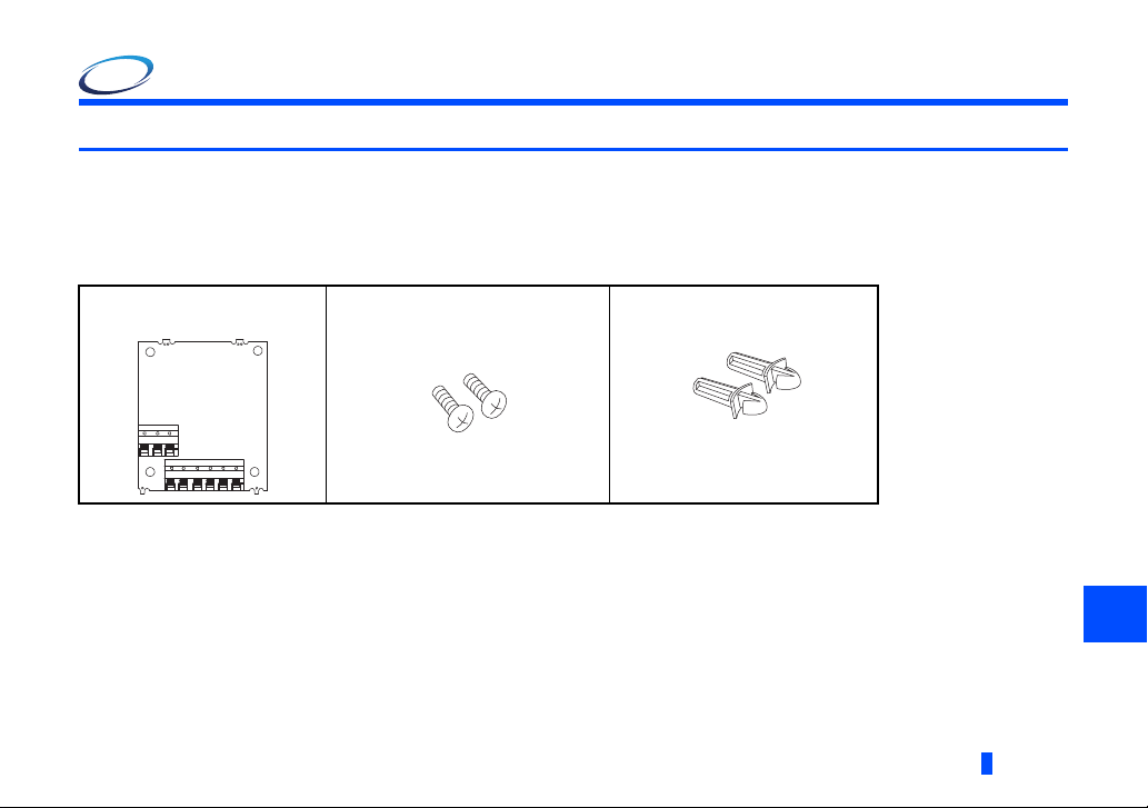
1.1.1 Product confirmation
Check the enclosed items.
Plug-in option
................................................1
Mounting screw (M3 8 mm)
.........................2 (Refer to page 8.)
Spacer
....................2 (Refer to page 8.)
PRE-OPERATION INSTRUCTIONS
1
5
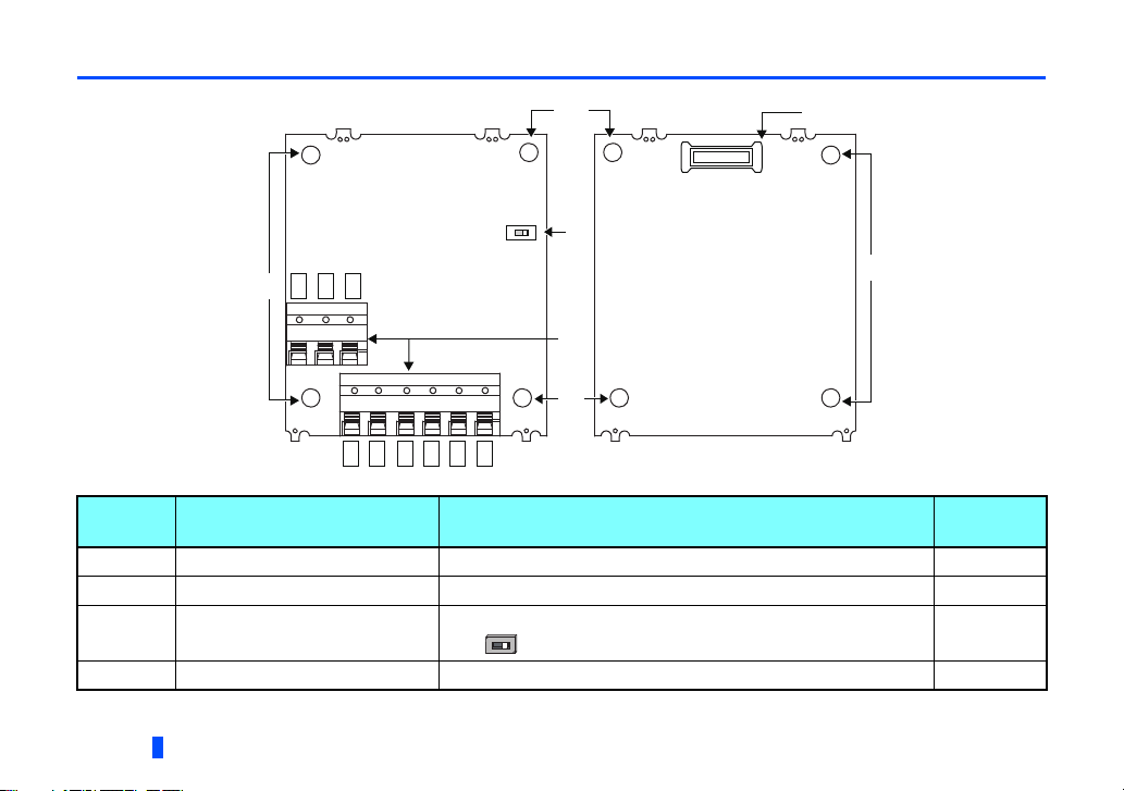
1.2 Component names
Front view Rear view
(a)
(d)
SW1
1A
1B
1C
2A
2B
2C
3A
3B
3C
(a)
O
N
(a)
(a)
(c)
(b)
Symbol Name Description
Switch for manufacturer setting. Do not change the initial setting.
N
O
(OFF )
a Mounting hole Fixes the option to the inverter with screws, or installs spacers. 8
b Terminal block Connects to devices that receive signals from the inverter. 11
c
Switch for manufacturer setting
(SW1)
d Connector Connects to the option connector of the inverter. 8
6
PRE-OPERATION INSTRUCTIONS
Refer to
page
―

1.3 Specifications
NOTE
Type of output signal
1 changeover contact output (three relays provided)
Contact capacity
230 VAC...0.3 A
30 VDC...0.3 A
• Use contacts within the rated capacity. Failure to do so may cause contacts to wear out quickly or to be welded.
1
PRE-OPERATION INSTRUCTIONS
7
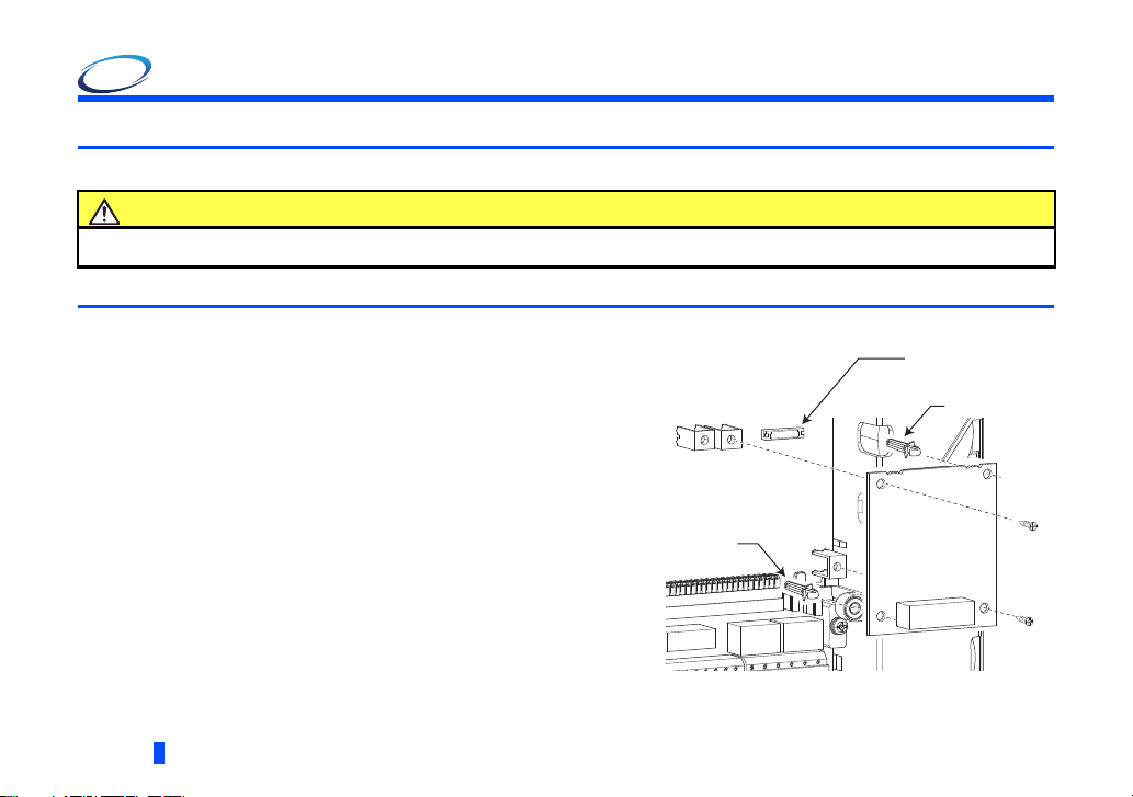
Spacer
Spacer
Option connector
on the inverter
Example of installation to connector 1
2 INSTALLATION AND WIRING
2.1 Pre-installation instructions
Check that the inverter's input power and the control circuit power are both OFF.
CAUTION
Do not install or remove this product while the inverter power is ON. Doing so may damage the inverter or this product.
To avoid damage due to static electricity, static electricity in your body must be discharged before you touch this product.
2.2 Installation procedure
(1) Remove the inverter front cover. (Refer to Chapter 2 of
the Instruction Manual (Detailed) of the inverter for
instructions for removing the front cover.)
(2) Insert two spacers into the mounting holes that will not be
filled with mounting screws (see the diagrams on the next
page to identify the holes).
(3) Fit the board mounted option connector on this product to
the guide of the option connector on the inverter and
insert the plug-in option as far as it goes. (Select option
connector 1 or 2 on the inverter.)
(4) Fit the two locations, the left and right, of the plug-in
option securely to the inverter unit by screwing in the
supplied mounting screws (tightening torque 0.33 N∙m to
0.40 N∙m). If the screw holes do not line up, the connector
may not be inserted deep enough. Check the connector.
8
INSTALLATION AND WIRING
 Loading...