

Page 1
Page 2

Page 3

MELDAS is a registered trademark of Mitsubishi Electric Corporation.
Other company and product names that appear in this manual are trademarks or
registered trademarks of the respective companies.
Page 4

Page 5

Introduction
This manual is the alarm/parameter guide required to use the MITSUBISHI CNC700/70 Series.
This manual is prepared on the assumption that your machine is provided with all of the MITSUBISHI
CNC700/70 Series functions. Confirm the functions available for your NC before proceeding to operation
by referring to the specification issued by the machine tool builder.
Notes on Reading This Manual
(1) This manual explains general parameters as viewed from the NC.
For information about each machine tool, refer to manuals issued from the machine tool builder.
If the descriptions relating to "restrictions" and "allowable conditions" conflict between this manual
and the machine tool builder's instruction manual, the later has priority over the former.
(2) This manual is intended to contain as much descriptions as possible even about special operations.
The operations to which no reference is made in this manual should be considered impossible.
(3) The "special display unit" explained in this manual is the display unit incorporated by the machine
tool builder, and is not the MITSUBISHI standard display unit.
Caution
If the descriptions relating to the "restrictions" and "allowable conditions" conflict between this
manual and the machine tool builder’s instruction manual‚ the latter has priority over the former.
The operations to which no reference is made in this manual should be considered
"impossible".
This manual is complied on the assumption that your machine is provided with all optional
functions. Confirm the functions available for your machine before proceeding to operation by
referring to the specification issued by the machine tool builder.
In some NC system versions‚ there may be cases that different pictures appear on the screen‚
the machine operates in a different way or some function is not activated.
Page 6

Page 7
Precautions for Safety
Always read the specifications issued by the machine tool builder, this manual, related manuals and attached
documents before installation, operation, programming, maintenance or inspection to ensure correct use.
Understand this numerical controller, safety items and cautions before using the unit.
This manual ranks the safety precautions into "DANGER", "WARNING" and "CAUTION".
DANGER
When the user may be subject to imminent fatalities or major injuries if handling is
mistaken.
WARNING
CAUTION
Note that even items ranked as "
case, important information that must always be observed is described.
Not applicable in this manual.
Not applicable in this manual.
When the user may be subject to fatalities or major injuries if handling is mistaken.
When the user may be subject to injuries or when physical damage may occur if
handling is mistaken.
CAUTION", may lead to major results depending on the situation. In any
DANGER
WARNING
1. Items related to product and manual
If the descriptions relating to the "restrictions" and "allowable conditions" conflict between this
manual and the machine tool builder's instruction manual‚ the latter has priority over the former.
The operations to which no reference is made in this manual should be considered impossible.
This manual is complied on the assumption that your machine is provided with all optional
functions. Confirm the functions available for your machine before proceeding to operation by
referring to the specification issued by the machine tool builder.
In some NC system versions‚ there may be cases that different pictures appear on the screen‚
the machine operates in a different way on some function is not activated.
2. Items related to faults and abnormalities
If the battery low alarm is output, save the machining programs, tool data and parameters to an
input/output device, and then replace the battery. If the BATTERY alarm occurs, the machining
programs, tool data and parameters may be damaged. After replacing the battery, reload each
data item.
CAUTION
[Continued on next page]
Page 8
CAUTION
3. Items related to maintenance
Do not replace the battery while the power is ON.
Do not short-circuit, charge, heat, incinerate or disassemble the battery.
Dispose of the spent battery according to local laws.
Do not connect or disconnect the connection cables between each unit while the power is ON.
Do not pull the cables when connecting/disconnecting it.
Do not replace cooling fan while the power is ON.
Dispose of the replaced cooling fan according to the local laws.
Do not replace backlight while the power is ON.
Dispose of the spent backlights according to the local laws.
Do not touch backlight while the power is ON. Failure to observe this could result in electric shocks
due to high voltage.
Do not touch backlight while LCD panel is in use. Failure to observe this could result in burns.
LCD panel and backlight are made of glass, so do not apply impacts or pressure on them. Failure to
observe this could result in breakage.
Incorrect connections could cause the devices to damage. Connect the cable to the designated
connector.
[Continued]
Do not replace control units while the power is ON.
Do not replace display units while the power is ON.
Do not replace keyboard units while the power is ON.
Do not replace DX units while the power is ON.
Do not replace hard disk units while the power is ON.
Dispose of the replaced hard disk unit according to the local laws.
Hard disk unit is a precision device, so do not drop or apply strong impacts on it.
4. Items related to servo parameters and spindle parameters
Do not adjust or change the parameter settings greatly as operation could become unstable.
In the explanation on bits, set all bits not used, including blank bits, to "0".
Page 9

CONTENTS
I Procedures for Starting up
1. Procedures for Starting Up 700 Series........................................................................................1
1.1 Outline of Hardware Configuration.........................................................................................1
1.2 Outline of Setup Procedures ..................................................................................................2
2. Procedures for Starting Up 70 Series..........................................................................................3
2.1 Outline of Hardware Configuration.........................................................................................3
2.2 Outline of Setup Procedures ..................................................................................................4
3. Setup Details ...............................................................................................................................5
3.1 Connecting the Control Unit and Peripheral Devices.............................................................5
3.1.1 Setting the MDS-D/DH Series Rotary Switch and DIP Switch.........................................7
3.1.2 Setting the MDS-D-SVJ3/SPJ3 Series Rotary Switch......................................................9
3.2 Erasing the Backed up Data (SRAM)...................................................................................10
3.3 Inputting the Parameters......................................................................................................12
3.3.1 When There is No Parameter File..................................................................................12
3.3.2 When a Parameter File is Available...............................................................................15
3.4 Formatting the File System...................................................................................................16
3.5 Inputting the Ladder Program...............................................................................................17
3.6 Credit System.......................................................................................................................19
3.7 Setting the Handy Terminal..................................................................................................21
3.7.1 When Connecting with PC to Input ................................................................................21
3.7.2 When Connecting with NC to Input................................................................................23
3.8 Adjustment of Dog-type Reference Position Return for Relative Position Detection............24
3.8.1 Dog-type Reference Position Return Operation.............................................................24
3.8.2 Dog-type Reference Position Return Adjustment Procedures.......................................25
3.9 Absolute Position Detection System.....................................................................................31
3.9.1 Dog-type Reference Position Return Operation.............................................................31
3.9.2 Starting up the Absolute Position Detection System......................................................32
3.10 Auxiliary Axis Operation .....................................................................................................34
3.10.1 Preparations.................................................................................................................35
3.10.2 Absolute Position Initial Setting....................................................................................36
3.10.3 Test Operation..............................................................................................................36
3.10.4 PLC device...................................................................................................................37
3.10.5 Notes............................................................................................................................40
3.11 Data Sampling....................................................................................................................41
3.12 Data backup .......................................................................................................................41
3.13 M70 SETUP INSTALLER...................................................................................................42
3.13.1 Compatible Data and CF Card Folder Configuration ...................................................42
3.13.2 Operation Method.........................................................................................................44
3.13.3 List of Error Messages .................................................................................................49
4. 700 Series H/W Replacement Methods.....................................................................................50
4.1 Durable Parts........................................................................................................................50
4.1.1 Control unit battery.........................................................................................................50
4.1.2 Cooling fan for control unit .............................................................................................52
4.1.3 Cooling fan for display unit (XP terminal).......................................................................53
Page 10

4.1.4 Backlight.........................................................................................................................54
4.2 Unit .......................................................................................................................................57
4.2.1 Control Unit.....................................................................................................................57
4.2.2 Display Unit ....................................................................................................................59
4.2.3 Keyboard unit .................................................................................................................60
4.2.4 DX Unit...........................................................................................................................62
4.2.5 Hard Disk Unit ................................................................................................................63
4.3 Compact Flash......................................................................................................................64
Control Unit Compact Flash ............................................................................................64
4.3.1
4.4 IC card..................................................................................................................................65
4.4.1
Front IC Card ..................................................................................................................65
5. 70 Series H/W Replacement Methods.......................................................................................66
5.1 Durable Parts........................................................................................................................66
5.1.1 Control unit battery.........................................................................................................66
5.1.2 Backlight.........................................................................................................................68
5.2 Unit .......................................................................................................................................70
5.2.1 Control Unit.....................................................................................................................70
5.2.2 Display Unit ....................................................................................................................72
5.2.3 Keyboard unit .................................................................................................................73
5.2.4 DX Unit...........................................................................................................................75
5.3 Compact Flash......................................................................................................................76
5.3.1 Front Compact Flash......................................................................................................76
6. Cable ......................................................................................................................................77
II Explanation of Alarms
1. List of Alarms...............................................................................................................................1
1.1 Operation Alarms....................................................................................................................1
1.2 Stop Codes...........................................................................................................................10
1.3 Servo/Spindle Alarms...........................................................................................................15
1.4 MCP Alarm ...........................................................................................................................25
1.5 System Alarms......................................................................................................................35
1.6 Absolute Position Detection System Alarms.........................................................................41
1.7 Distance-coded Reference Scale Errors ..............................................................................44
1.8 Messages during Emergency Stop.......................................................................................45
1.9 Auxiliary Axis Alarms............................................................................................................47
1.10 Computer Link Errors..........................................................................................................54
1.11 User PLC Alarms................................................................................................................55
1.12 Network Service Errors.......................................................................................................57
2. Operation Messages..................................................................................................................58
2.1 Search-related Operation Messages....................................................................................58
2.2 Graphic Display-related Operation Messages......................................................................59
2.3 Variable (Common variables, local variables) - related Operation Messages......................60
2.4 PLC Switch-related Operation Messages.............................................................................60
2.5 Compensation-related (Tool compensation, coordinate system offset) Operation Messages60
2.6 Data Input/Output-related Operation Messages...................................................................61
Page 11

2.7 Parameter-related Operation Messages ..............................................................................64
2.8 Measurement-related (Workpiece, rotation) Operation Messages.......................................65
2.9 Tool (Tool registration, tool life) -related Operation Messages.............................................67
2.10 Editing-related Operation Messages..................................................................................68
2.11 Diagnosis-related Operation Messages .............................................................................70
2.12 Maintenance-related Operation Messages.........................................................................71
2.13 Data Sampling-related Operation Messages......................................................................73
2.14 Absolute Position Detection-related Operation Messages.................................................74
2.15 System Setup-related Operation Messages.......................................................................74
2.16 Automatic Backup-related Operation Messages................................................................75
2.17 Alarm History-related Operation Messages........................................................................75
2.18 Anshin-net-related Operation Messages............................................................................76
2.19 Messages Related to Machine Tool Builder Network System............................................81
2.20 Other Operation Messages ................................................................................................83
3. Program Error............................................................................................................................84
4. Troubleshooting.......................................................................................................................104
4.1 Drive System Troubleshooting ...........................................................................................104
4.1.1 Troubleshooting at Power ON......................................................................................104
4.1.2 Troubleshooting for each alarm No..............................................................................105
4.1.3 Troubleshooting for each warning No. .........................................................................130
4.1.4 Parameter numbers during initial parameter error .......................................................132
4.1.5 Troubleshooting the spindle system when there is no alarm or warning......................133
III Explanation of Parameters
1. Outline .........................................................................................................................................1
1.1 Screen Transition Chart..........................................................................................................1
1.2 Unit.........................................................................................................................................1
2. User Parameters..........................................................................................................................2
2.1 Process Parameters...............................................................................................................2
2.2 Control Parameters ..............................................................................................................15
2.3 Axis Parameters...................................................................................................................19
2.4 Operation Parameters..........................................................................................................22
2.5 Barrier Data (For L system only) ..........................................................................................27
2.6 I/O Parameters.....................................................................................................................30
2.7 Ethernet Parameters ............................................................................................................49
2.8 Computer Link Parameters...................................................................................................56
2.9 Subprogram Storage Destination Parameters......................................................................59
2.10 Anshin-net Parameter 1......................................................................................................63
2.11 Machine Tool Builder Network System (MTB-net) Parameter 1.........................................64
3. Setting the Machine Parameters ...............................................................................................65
4. Base Specifications Parameters................................................................................................66
5. Axis Specifications Parameters...............................................................................................123
5.1 Axis Specifications Parameters..........................................................................................123
5.2 Zero Point Return Parameters............................................................................................129
Page 12

5.3 Absolute Position Parameters ............................................................................................ 134
5.4 Axis Specifications Parameters 2.......................................................................................136
6. Servo Parameters....................................................................................................................148
6.1 Details for servo parameters...............................................................................................148
6.2 List of standard parameters for each servomotor...............................................................166
6.3 Supplement.........................................................................................................................174
6.3.1 D/A Output No..............................................................................................................174
6.3.1.1 MDS-D/DH Series................................................................................................................. 174
6.3.1.2 MDS-D-SVJ3 Series............................................................................................................. 177
6.3.2 Electronic Gears...........................................................................................................180
6.3.3 Lost Motion Compensation...........................................................................................181
7. Spindle Parameters .................................................................................................................182
7.1 Spindle Base Specifications Parameters............................................................................182
7.2 Spindle Parameters............................................................................................................198
7.3 Supplement.........................................................................................................................221
7.3.1 D/A Output Numbers....................................................................................................221
7.3.1.1 MDS-D/DH Series................................................................................................................. 221
7.3.1.2 MDS-D-SPJ3 Series............................................................................................................. 225
8. Rotary Axis Configuration Parameters.....................................................................................229
9. Machine Error Compensation ..................................................................................................235
9.1 Function Outline..................................................................................................................235
9.2 Setting Compensation Data................................................................................................239
9.3 Example in Using a Linear Axis as the Base Axis..............................................................241
9.4 Example in Using a Rotary Axis as the Base Axis..............................................................245
10. PLC Constants.......................................................................................................................246
10.1 PLC Timer.........................................................................................................................246
10.2 PLC Integrated Timer .......................................................................................................247
10.3 PLC Counter.....................................................................................................................247
10.4 PLC Constants..................................................................................................................248
10.5 Selecting the PLC Bit........................................................................................................248
11. Macro List ..............................................................................................................................251
12. Position Switch.......................................................................................................................253
12.1 Canceling the Position Switch ..........................................................................................255
13. Auxiliary Axis Parameter........................................................................................................256
14. Open Parameter ....................................................................................................................275
15. CC-Link Parameter ................................................................................................................276
15.1 CC-Link Parameter 1........................................................................................................276
15.2 CC-Link Parameter 2........................................................................................................287
16. Anshin-net Parameter 2 / MTB-net Parameter 2....................................................................290
17. PLC Axis Parameters.............................................................................................................303
Page 13

I Procedures for Starting Up
Page 14

Page 15
1. Procedures for Starting Up 700 Series
A
A
1.1 Outline of Hardware Configuration
1. Procedures for Starting Up 700 Series
This section explains the normal work required to newly start up the MITSUBISHI CNC 700 Series.
Start up the system following these setup procedures.
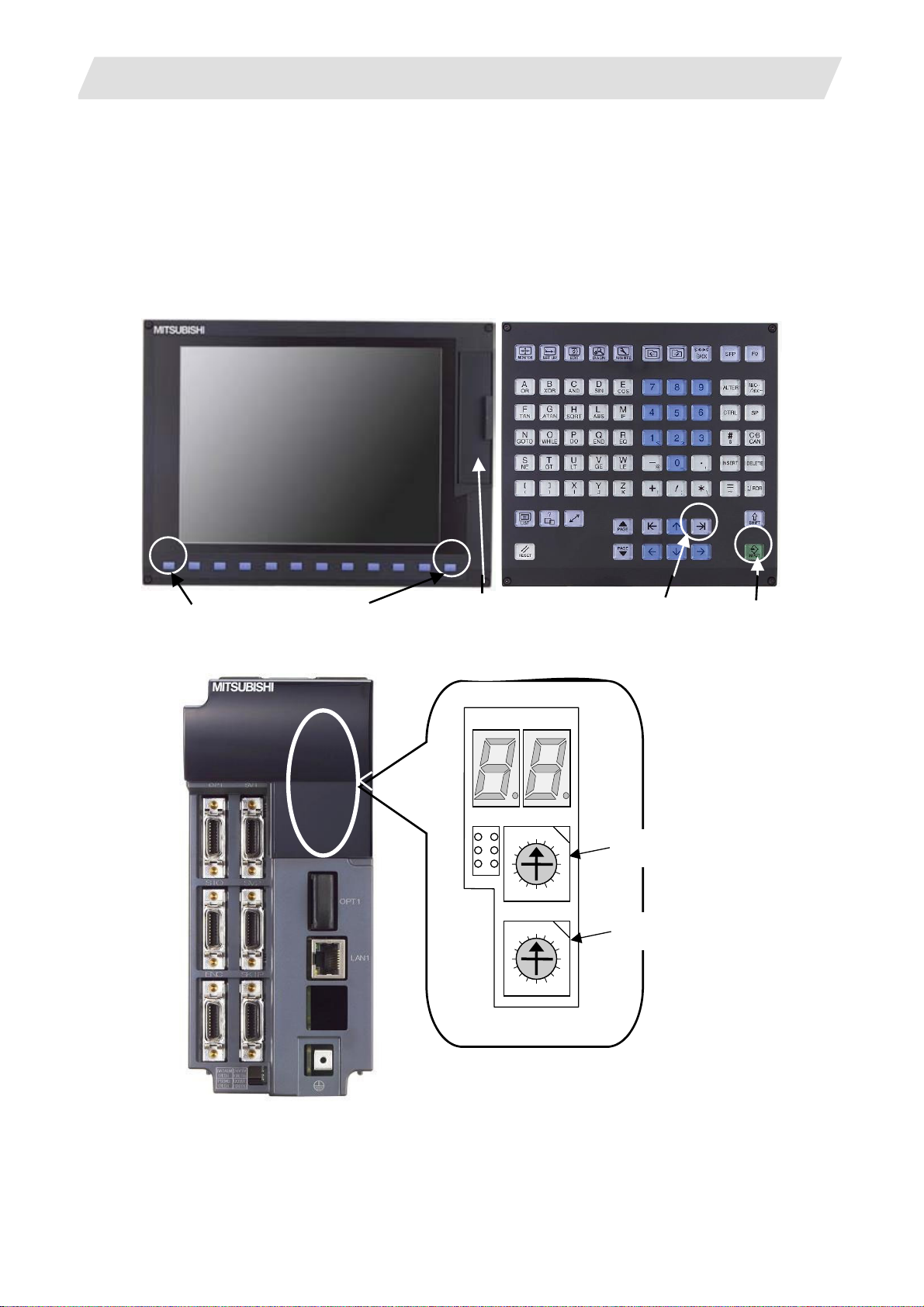
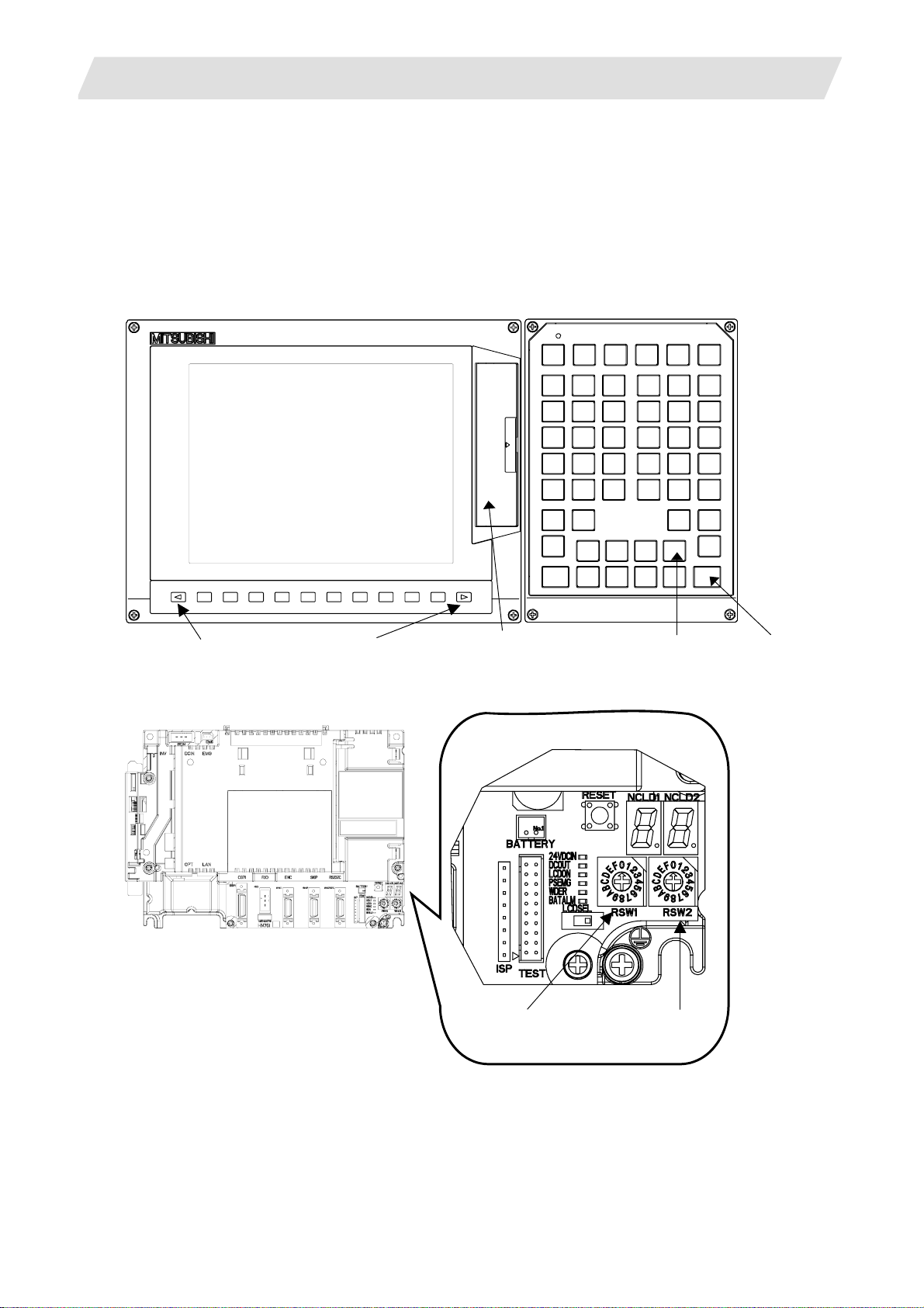
1.1 Outline of Hardware Configuration
The names of the hardware used in this section's explanations are explained belo w.
Display unit Keyboard
Back
Next
IC card interface on front of
display unit
Tab right
INPUT
Control unit
LED1
SW1
D
B
LED2
CS1
0
F
8
1
2 E
3
4C
5
6
79
Upper rotary switch
CS2
0
1
F
2 E
D
B
3
4C
5
6
79
8
Lower rotary switch
I - 1
Page 16
1. Procedures for Starting Up 700 Series
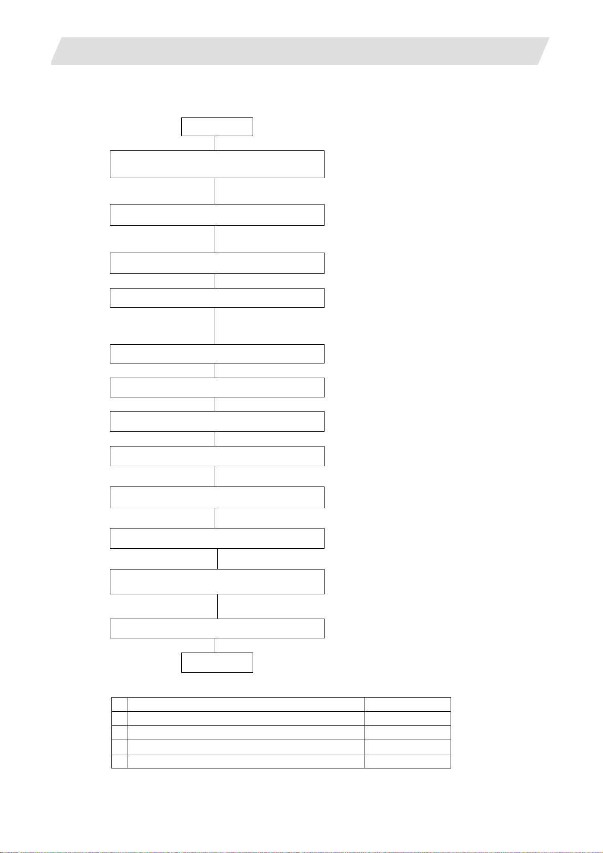
1.2 Outline of Setup Procedures
The procedures for setting up are explained with a flow chart.
Start
Connecting the control unit
and peripheral devices
Connect the control unit with the peripheral devices (servo/spindle drive,
auxiliary axis, remote I/O).
Erasing the backed up data (SRAM)
1.2 Outline of Setup Procedures
Refer to 3.1
Refer to 3.2
Turning the power ON again.
Inputting the parameters
Erase the backed up data (SRAM).
Set CS1 to "0" and CS2 to "C" to erase the SRAM.
Refer to 3.3
If there is no parameter file, input the parameters with system setup or
by manual input operation.
If there is a parameter file, input the parameters with input/output screen.
Turning the power ON again.
Formatting the file system
Refer to 3.4
Format the file system
Turning the power ON again.
Setting the data/time
Refer to 700/70 Series Instruction Manual
Set the data and time in the integrated time display pop-up window.
Inputting the ladder program
Refer to 3.5
Input the ladder program using "GX Developer" or "PLC Onboard".
Setting the credit system
Refer to 3.6
This is necessary only if the credit system is valid.
Setting the handy terminal
Input the customized data of handy terminal.
(Note) This is necessary only if the handy terminal is connected.
Refer to 3.7
Inputting the machining program
End
Carry out the procedures below if necessary.
1 Adjustment of dog-type reference position return Refer to 3.8
2 Absolute position detection system Refer to 3.9
3 Auxiliary axis operation Refer to 3.10
4 Data sampling Refer to 3.11
5 Data backup Refer to 3.12
I - 2
Page 17
2. Procedures for Starting Up 70 Series
2.1 Outline of Hardware Configuration
2. Procedures for Starting Up 70 Series
This section explains the normal work required to newly start up the MITSUBISHI CNC 70 Series.
Start up the system following these setup procedures.
2.1 Outline of Hardware Configuration
The names of the hardware used in this section's explanations are explained belo w.
Display unit Keyboard
Back Next
Control unit
CF card interface on front
of display unit
Left rotary switch
Right rotary switch
Tab right INPUT
I - 3
Page 18
2. Procedures for Starting Up 70 Series
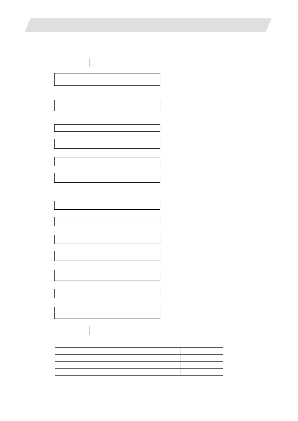
2.2 Outline of Setup Procedures
The procedures for setting up are explained with a flow chart.
Start
Connecting the control unit
and peripheral devices
Connect the control unit with the peripheral devices (servo/spindle drive,
and remote I/O).
Erasing the backed up data (SRAM)
2.2 Outline of Setup Procedures
Refer to 3.1
Refer to 3.2
Erase the backed up data (SRAM).
Set RSW1 to "0" and RSW2 to "C" to erase the SRAM.
Turning the power ON again.
Setting up with M70 SETUP INSTALLER
Install the language data, custom data and custom startup screen.
Turning the power ON again.
Inputting the parameters
If there is no parameter file, input the parameters with system setup or
by manual input operation.
If there is a parameter file, input the parameters with input/output screen.
Turning the power ON again.
Formatting the file system
Format the file system
Turning the power ON again.
Setting the data/time
Refer to 3.13
Refer to 3.3
Refer to 3.4
Refer to 700/70 Series Instruction Manual
Set the data and time in the integrated time display pop-up window.
Inputting the ladder program
Refer to 3.5
Input the ladder program using "GX Developer".
Setting the credit system
Refer to 3.6
This is necessary only if the credit system is valid.
Inputting the machining program
End
Carry out the procedures below if necessary.
1 Adjustment of dog-type reference position return Refer to 3.8
2 Absolute position detection system Refer to 3.9
3 Data sampling Refer to 3.11
4 Data backup Refer to 3.12
I - 4
Page 19
3. Setup Details
3.1 Connecting the Control Unit and Peripheral Devices
3. Setup Details
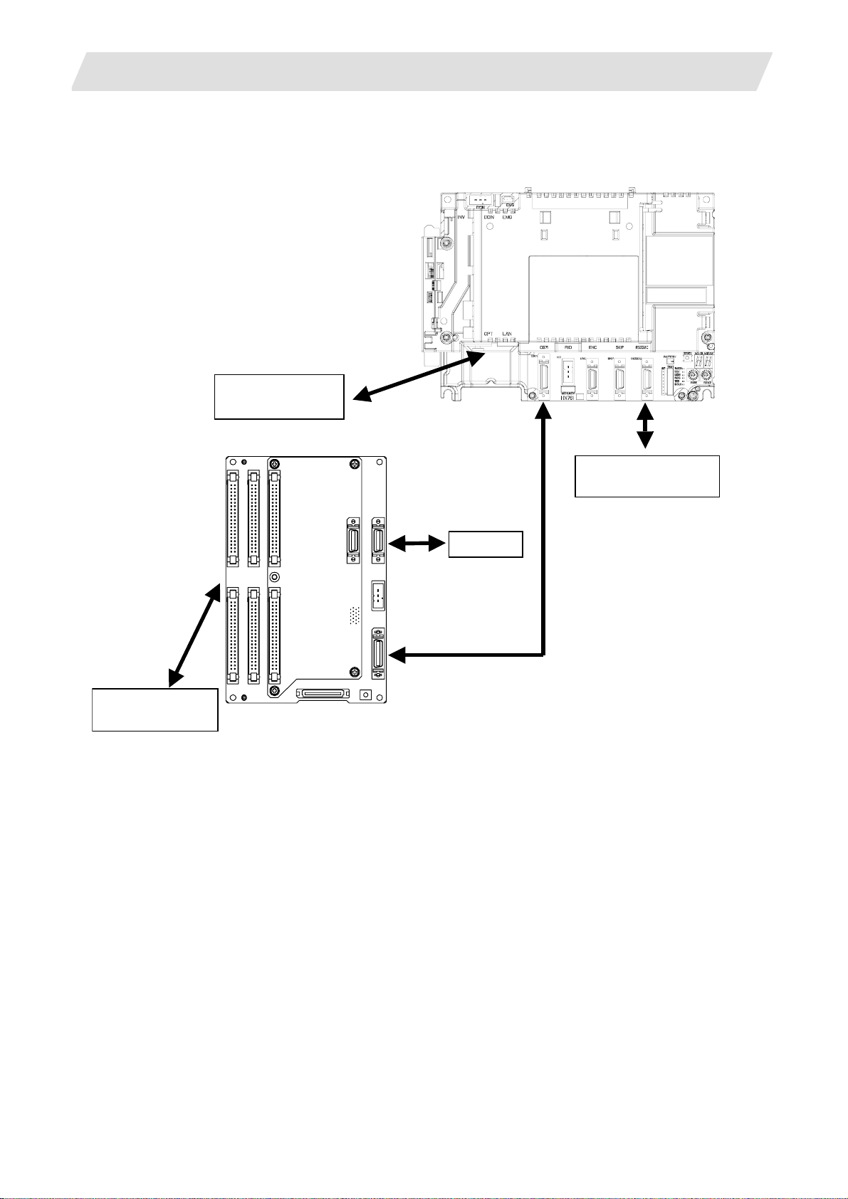
3.1 Connecting the Control Unit and Peripheral Devices
Connect the control unit with the peripheral devices (servo/spindle drive, auxiliary axis, remote IO, handy
terminal).
Refer to "Mitsubishi CNC 700 Series Connection Manual" (IB-1500034), “Mitsubishi CNC 70 Series
Connection Manual” (IB-1500254), "MDS-D Specifications Manual" (IB-15000011), and "MDS-DH
Specifications Manual" (IB-1500003) for details.
(1) 700 Series
Operation panel I/O unit
Control unit
Machine operation
panel
Handy terminal
Serial connection (RS-232C)
Handy terminal handle
Servo drive
Spindle drive
Auxiliary axis
I - 5
Page 20
3. Setup Details
(2) 70 Series
3.1 Connecting the Control Unit and Peripheral Devices
Servo drive
Spindle drive
Operation panel I/O unit
Control unit
Serial communicaton
(RS-232C)
Machine operation
panel
Handle
I - 6
Page 21
3. Setup Details
3.1 Connecting the Control Unit and Peripheral Devices
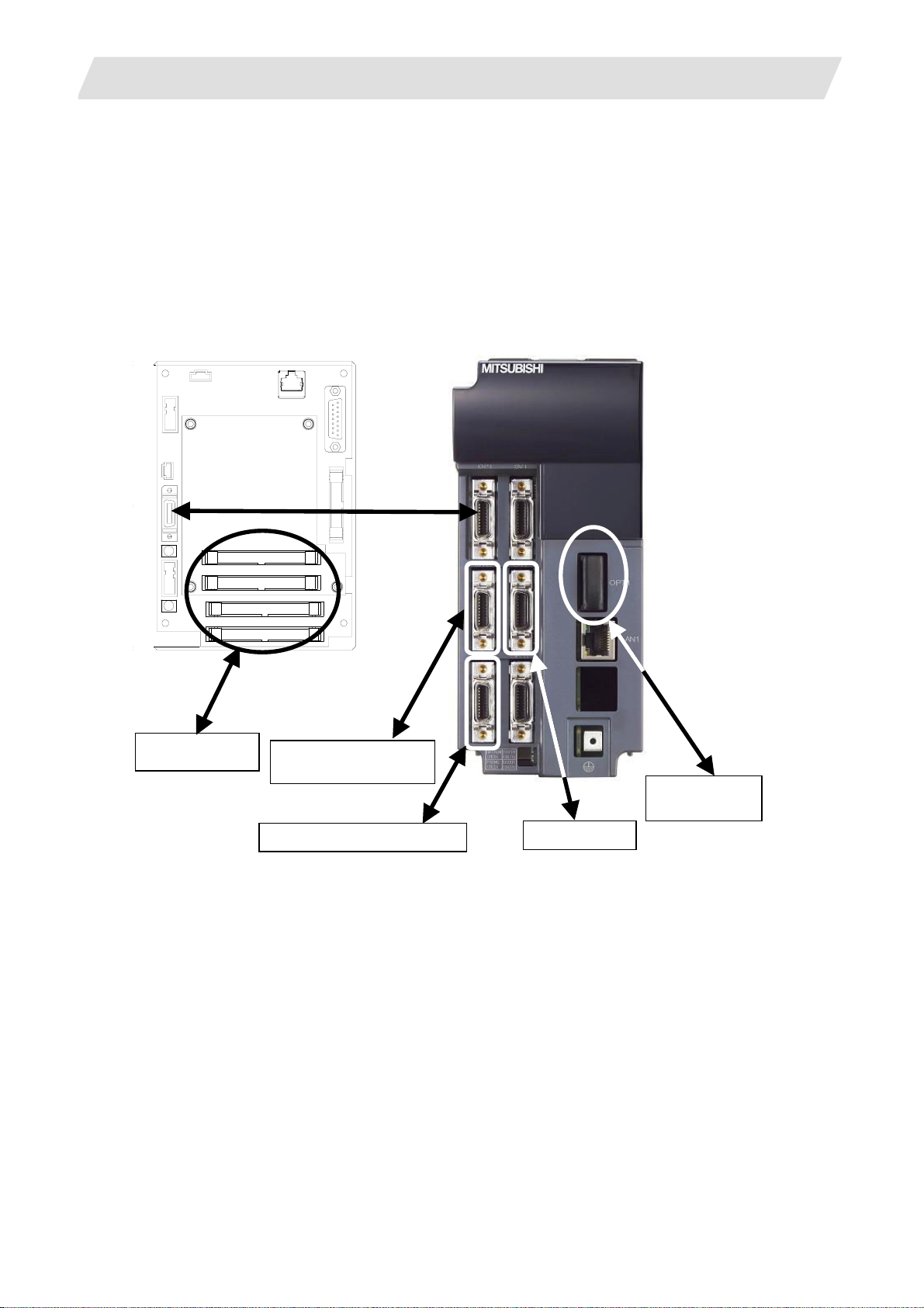
3.1.1 Setting the MDS-D/DH Series Rotary Switch and DIP Switch
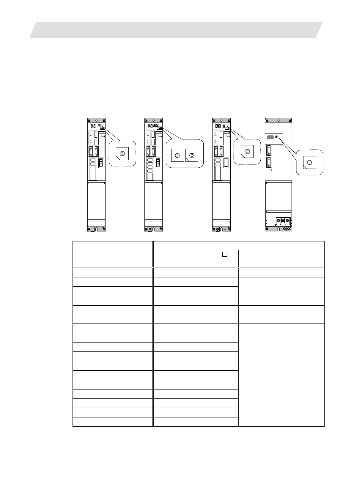
(1) Rotary switch setting
Before turning on the power, the axis No. must be set with the rotary switch. The rotary switch
settings will be validated when the drive units are turned ON.
1st axis
Servo drive unit
(MDS-D/DH-V1)
2nd axis
Servo drive unit
(MDS-D/DH-V2)
Spindle
Drive unit
(MDS-D/DH-SP□)
Power supply unit
(MDS-D/DH-CV)
8
7 9
6 A
5 B
4 C
3 D
2 E
1 F
0
8
7 9
6 A
5 B
4 C
3 D
2 E
1 F
0
8
7 9
6 A
5 B
4 C
3 D
2 E
1 F
0
L axis M axis
8
8
7 9
7 9
6 A
6 A
5 B
5 B
4 C
4 C
3 D
3 D
2 E
2 E
1 F
1 F
0
0
Details
Rotary switch setting
MDS-D/DH-V1/V2/SP
setting
MDS-D/DH-CV
setting
0 1st axis Normal setting
1 2nd axis
2 3rd axis
Setting prohibited
3 4th axis
4 5th axis
External emergency stop valid
(CN23 used)
5 6th axis
6 7th axis
7 8th axis
8 9th axis
9 10th axis
A 11th axis Setting prohibited
B 12th axis
C 13th axis
D 14th axis
E 15th axis
F 16th axis
I - 7
Page 22
3. Setup Details
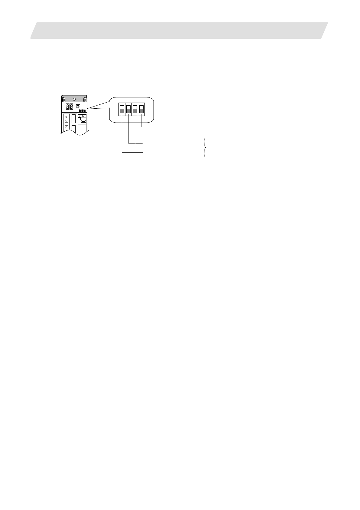
(2) DIP switch setting
Setting the DIP switches is necessary prior to turning ON the power. Setting of the DIP switches at
the time of turning ON the power is validated. The DIP switches shall be as the standard setting (all
the switches OFF).
3.1 Connecting the Control Unit and Peripheral Devices
The switches are OFF when facing bottom as illustrated.
Turn this switch ON for the drive unit to which the terminator is connected.
Note that the switch must be turned OFF when the network configuration is valid.
M axis Setting unused axis
L axis Setting unused axis
Unused axis can be set by turning the switches ON.
When there is unused axis for the 2-axis drive unit,
set unused axis.
(Note) If the NC system is compatible with A1 or the prior version, set "1" to the base specifications
parameter "#1240 set12/bit4" and turn the last DIP switch ON.
I - 8
Page 23
3. Setup Details
3.1 Connecting the Control Unit and Peripheral Devices
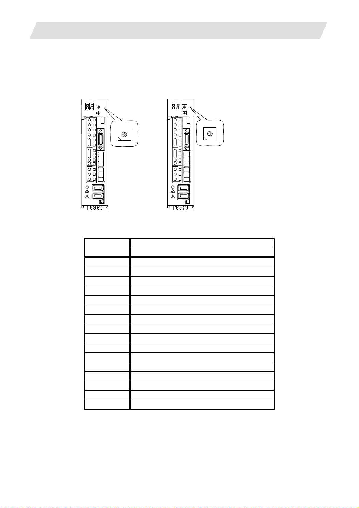
3.1.2 Setting the MDS-D-SVJ3/SPJ3 Series Rotary Switch
Before turning on the power, the axis No. must be set with the rotary switch. The rotary switch settings will
be validated when the drive units are turned ON.
Servo drive unit
(MDS-D-SVJ3)
Spindle drive unit
(MDS-D-SPJ3)
5 B
4 C
3 D
8
7 9
6 A
2 E
1 F
0
4 C
8
7 9
6 A
5 B
3 D
2 E
1 F
0
Details Setting the
rotary switch
Setting the MDS-D-SVJ3/SPJ3
0 1st axis
1 2nd axis
2 3rd axis
3 4th axis
4 5th axis
5 6th axis
6 7th axis
7 8th axis
8 9th axis
9 10th axis
A 11th axis
B 12th axis
C 13th axis
D 14th axis
E 15th axis
F 16th axis
I - 9
Page 24
3. Setup Details
A
A
A
A
3.2 Erasing the Backed up Data (SRAM)
3.2 Erasing the Backed up Data (SRAM)
Use the following procedure if the backed up data (SRAM) needs to be cleared after the control unit is
replaced, etc. (There is no influence on the option parameters even if the backup data is deleted.)
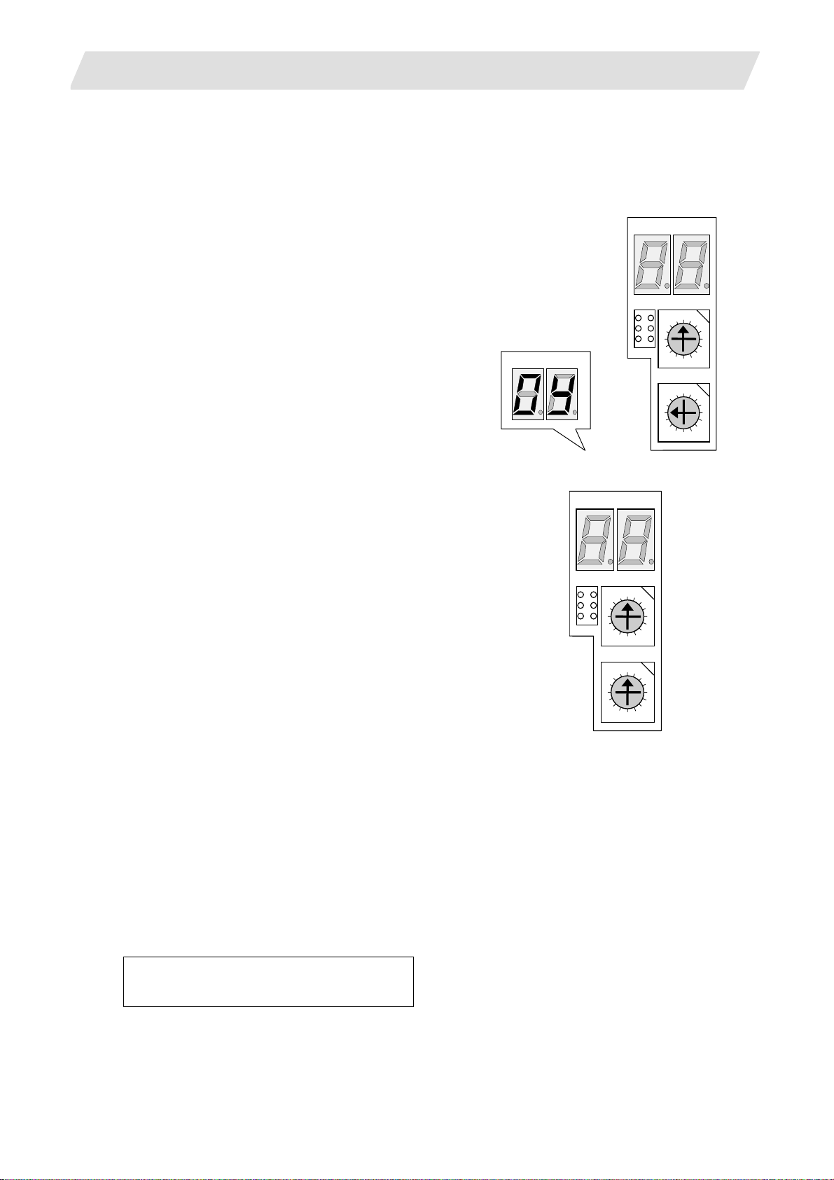
(1) 700 Series
(a) With the NC power OFF, set the upper rotary
switch (CS1) on the control unit to "0" and the
lower rotary switch (CS2) to "C". Then, turn the
power ON.
LED1 LED2
SW1
LED1
D
B
D
B
E
LED2
CS1
F
CS2
F
0
1
2 E
3
4C
5
6
79
8
0
1
2
3
4C
5
6
79
8
(b) The LED display will change from "08." → "00" →
LED1
LED2
"01" ... "08". The process is completed when "0Y"
is displayed. (Required time: 8 seconds)
(c) Turn the NC power OFF.
(d) Set the lower rotary switch (CS2) to "0".
SW1
D
B
D
B
CS1
0
F
8
CS2
0
F
8
1
2 E
3
4 C
5
6
7 9
1
2 E
3
4 C
5
6
7 9
(e) After turning the power OFF and O N, do nothing, and then turn the power OFF and ON again.
(Note) After the SRAM is cleared and the NC power is turned ON, the IP addresses are initialized to the
following values.
<Base common parameters>
#1934 Local IP address : 192.168.100. 1
#1935 Local Subnet mask : 255.255.255. 0
To communicate with the screen, the parameter value and the "C:\WINDOWS\melcfg.ini" setting value
must match. Confirm that "C:\WINDOWS\melcfg.ini" is set to the above value.
Last line of C:\WINDOWS\melcfg.ini
• • •
[HOSTS]
TCP1=192.168.100.1,683
I - 10
Page 25
3. Setup Details
A
A
A
A
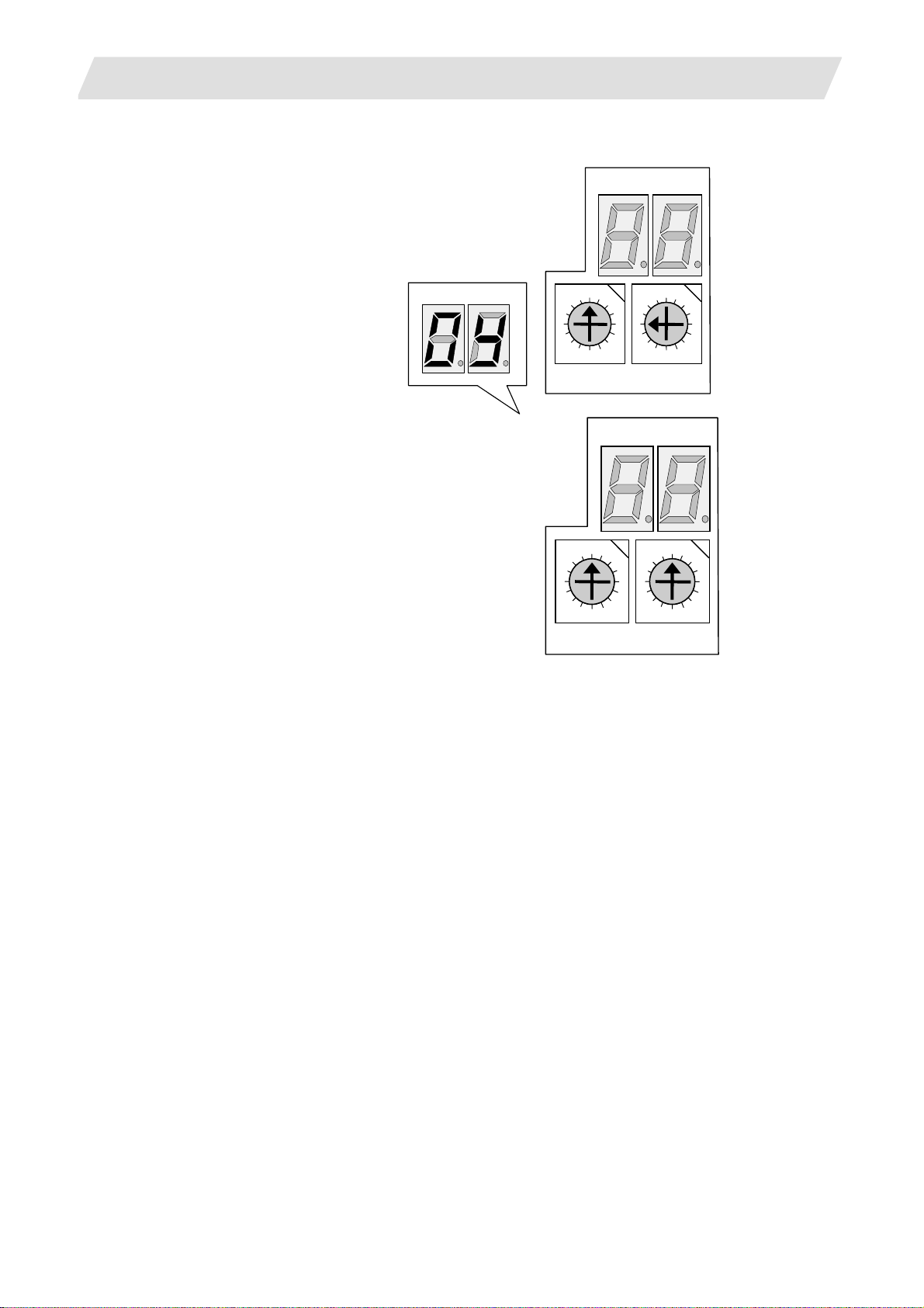
(2) 70 Series
(a) With the NC power OFF, set the left rotary switch
(RSW1) on the control unit to "0" and the right
rotary switch (RSW2) to "C". Then, turn the power
ON.
3.2 Erasing the Backed up Data (SRAM)
NCLD1
NCLD2
NCLD1 NCLD2
0
1
F
D
B
2 E
3
4C
5
6
79
8
0
1
F
D
B
2 E
3
4 C
5
6
7 9
8
RSW2 RSW1
(b) The LED display will change from "08." → "00" →
"01" ... "08". The process is completed when "0Y"
NCLD1
NCLD2
is displayed. (Required time: 8 seconds)
(c) Turn the NC power OFF.
(d) Set the right rotary switch (RSW2) to "0".
0
1
F
D
B
2 E
3
4C
5
6
79
8
0
1
F
2 E
D
B
RSW2 RSW1
3
4 C
5
6
7 9
8
(e) After turning the power OFF and O N, do nothing, and then turn the power OFF and ON again.
I - 11
Page 26

3. Setup Details
3.3 Inputting the Parameters
3.3 Inputting the Parameters
3.3.1 When There is No Parameter File
If there is no parameter file (ALL.PRM), input the parameters with system setup or by manual input operation.
(1) Parameter input with system setup
With the system setup function, various setups necessary for the NC to initially startup are available by
simply entering the minimum required items. File formatting can be done at the same time.
Items required for setting with system setup are as follows.
● Display language, number of spindle connections, number of auxiliary axis connections
(for 700 Series only)
● Number of axes and command type for each part system
● Servo I/F connection channel and rotary switch setting for each spindle.
Also, type of converter connected with each spindle drive.
● Servo I/F connection channel and rotary switch setting for each servo axis.
Also, type of converter connected with each servo drive.
For details, refer to the section "system setup screen" in the instruction manual.
(2) Parameter input by manual input operation
(a) Select "MAINTENANCE (Mainte)" → "Mainte" → "Psswd input", and input "MPARA". Then, press
INPUT.
(b) Select the "Retn" menu
→ "Param", and set the various parameters such as the base
specifications parameters and axis specification parameters according to the machi ne configuration.
The minimum required parameters are listed below. Refer to "III Explanation of Parameters" for
details on each parameter.
(b-1) Set the number of NC axes, number of spindles and number of auxiliary axes, and then turn the
power ON again.
Type # Item
Base system
1002 axisno Number of axes
parameter
1039 spinno Number of spindles Base common
parameters
1044 auxno MR-J2-CT connections (for 700 Series only)
I - 12
Page 27

3. Setup Details
(b-2) Set the minimum required parameters such as the axis name.
Base axis specification
parameters
Base common
parameters
Axis specification
parameters
Zero point return
parameter
Servo parameters 2201
Spindle specification
parameters
Spindle parameters 13001
3.3 Inputting the Parameters
Type # Item
1013 axname Axis name
1021 mcp_no Drive unit I/F channel No. (Servo)
1022 axname2 2nd axis name
1155 DOOR_m Signal input device 1 for door interlock II common for part
systems
1156 DOOR_s Signal input device 2 for door interlock II common for part
systems
2001 rapid Rapid traverse rate
2002 clamp Cutting federate for clamp function
2003 smgst Acceleration/deceleration modes
2004 G0tL G0 time constant (linear)
2005 G0t1 G0 time constant (primary delay)
2007 G1tL G1 time constant (linear)
2008 G1t1 G1 time constant (primary delay)
2102 skip_tL Skip time constant linear
2103 skip_t1 Skip time constant primary delay acceleration/
deceleration by software 2nd stage
2029 grspc Grid interval
:
2456
SV001
:
SV256
Servo parameters
3001 slimt1 Limit rotation speed
3005 smax1 Maximum rotation speed
3024 sout Spindle connection
3025 enc_on Spindle encoder
3031 smcp_no Drive unit I/F channel No. (Spindle)
3105 sut Speed reach range
3107 ori_spd Orientation command speed
3109 zdetspd Z phase detection speed
:
13240
SP1001
:
SP1240
Spindle parameters
I - 13
Page 28
3. Setup Details
(Setting example) For 3 NC axes (X, Y, Z) and 1 spindle axis (S)
NC
X
Drive unit rotary switch
No.
#1021 mcp_no 1001 1002 1003
#3031 smcp_no 1004
Y Z S
0 1 2 3
3.3 Inputting the Parameters
Power supply
unit
P
3rd axis for 1st channel
I - 14
Page 29
3. Setup Details
3.3 Inputting the Parameters
3.3.2 When a Parameter File is Available
If a parameter file is available, input the parameters using the input/output function.
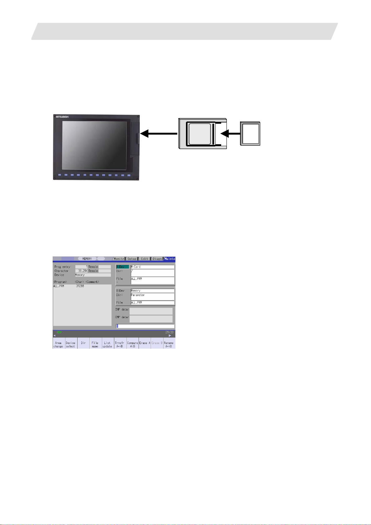
(Example) When files are available on a compact flash (CF) card
(1) Insert the CF card into the IC card interface on the front of the display unit.
Display unit
Adapter
CF card
(Note) 70 Series, which has the CF card interface,
does not need adapter.
(2) Select "MAINTENANCE (EDIT)" → "Input/Output".
(3) Confirm that device A is selected, and then select "Device select" → "Memory card".
(4) Select "File name" → "From list" → "ALL.PRM", and then press INPUT.
(5) Press "Area change", and select device B.
(6) Select "Device select" → "Memory".
(7) Select "Dir" → "Param".
* "ALL.PRM" is directly input as the file name.
(8) Press "Transfr A → B", and execute parameter input.
I - 15
Page 30

3. Setup Details
3.4 Formatting the File System
3.4 Formatting the File System
The base specification parameter "#1037 cmdtyp" must be set before the file system is formatted.
M System specifications : Set 1 or 2 according to the tool compensation type.
L System specifications : Select and set from 3 to 8 according to the G code list.
(1) Select "MAINTENANCE (Mainte)" → "NEXT" menu
(2) The message "Format NC memory (Y/N)?" will appear. Press "Y".
(3) When the memory is correctly formatted, the message "Format complete" will appear.
→ "Format".
(Note) When the parameter is set with system setup, the file system does not need to be formatted.
I - 16
Page 31

3. Setup Details
3.5 Inputting the Ladder Program
3.5 Inputting the Ladder Program
The ladder program can be created and input using the GX Developer installed in an external personal
computer or with the PLC onboard editing screen.
Refer to the "MITSUBISHI CNC 700 Series PLC Programming manual" (IB-1500036) for details.
The ladder program creation and input procedures are explained below with a flow chart.
(1) 700 Series
Start
Creation methods
Write with GX Developer
Connection method
Write to NC temporary
memory with Ethernet
communication
Create with GX Developer
Writing method
Write to NC temporary
memory with RS-232-C
Create with PLC onboard
Write to NC temporary
memory
Write with PLC onboard
Save ladder program on
IC card
Open ladder program in IC
card with PLC onboard
Write to NC temporary
memory
Write ladder program to NC ROM
End
I - 17
Page 32

3. Setup Details
(2) 70 Series
Start
Create with GX Developer
Write with GX Developer
3.5 Inputting the Ladder Program
Write to NC temporary
memory with Ethernet
communication
Write ladder program to NC ROM
Connection method
End
Write to NC temporary
memory with RS-232-C
I - 18
Page 33

3. Setup Details
3.6 Credit System
Encryption key and decryption code need to be set in order to validate credit system.
(1) Enter code key in the input/output
screen.
(a) Set the device name, directory and
file name in [A:Dev].
(b) Set "Memory" in device section and
"/CRE" in directory section of
[B:Dev].
Contens in directory section/file name
section will be written over.
Directroy section "Encryption Key"
File name section "ENCKEY.DAT"
3.6 Credit System
(c) Press the menu key [Trnsfr A→B].
(2) Enter cancel code in the input/output
screen.
(a) Set the device name, directory and
file name in [A:Dev].
(b) Set "Memory" in device section and
"/RLS" in directory section of [B:Dev].
Contens in directory section/file name
section will be written over.
Directory section "Decryption Code"
File name section "PASSCODE.DAT"
(c) Press the menu key [Trnsfr A→B].
I - 19
Page 34

3. Setup Details
(3) Turn the power ON again.
3.6 Credit System
Confirm that the expiration date (time limit)
is indicated in [DIAGN]-[Self diag] screen.
I - 20
Page 35

3. Setup Details
3.7 Setting the Handy Terminal
3.7 Setting the Handy Terminal
It is necessary to customize the display part composition, the key input, and the communication condition
with NC, etc. to connect the handy terminal (HG1T-SB12UH-MK1346-L*).
Create the customized data by "NC Designer HT", and download to the handy terminal.
There are two inputting methods of the handy terminal's costomaized data.
(1) Connecting PC and the handy terminal, the data is input from "NC Designer HT".
(2) Connecting NC and the handy terminal, the data is input from CF (Compact Flash).
3.7.1 When Connecting with PC to Input
Project data (*.p1t) h andled as customized data is cr eated by customized data cr eation tool "NC Designer
HT" and download to the handy terminal.
(1) Start the customized data creating tool "NC Designer HT" and create the project data (*.p1t).
(2) Connect PC and the handy terminal with serial (RS-232C).
(3) Select [Online] - [Communication setting] from the menu of "NC Designer HT", confirm the
communication condition is as follows.
Port : Set the PC side port.
Transmission :19200 [bps]
Data : 8 [bit]
Stop bit : 1
Parity : None
I - 21
Page 36

3. Setup Details
(4) Select [Online] - [Download] from the menu of "NC Designer HT".
(5) The following dialog box is displayed, so press the "Yes".
3.7 Setting the Handy Terminal
(6) If the passward is set to the downloaded costomazed data, the "Input password" dialog box is displayed.
So input the passward, press the "OK".
(7) The costomaized data is downloaded to the handy terminal.
(8) When the download has been completed, the following dialog box is displayed.
I - 22
Page 37

3. Setup Details
3.7 Setting the Handy Terminal
3.7.2 When Connecting with NC to Input
Download data (handy.cod) is created from project data (*.p1t) created by customized data creation tool "NC
Designer HT", and the customized data is downloaded to the handy terminal.
(1) Start the customized data creating tool "NC Designer HT" and create the project data (*.p1t).
(2) Select [File] - [Writing download data] from the menu of "NC Designer HT", and save the download data
named as "handy.cod" in the root directory of CF.
(3) Insert the CF created in the step (2) to the control unit.
(4) Set the passward which has been set to the handy terminal to "#11011 Handy TERM. PW."
(Note) When downloading the data for the first time, nothing is set to the parameter.
(5) NC power supply is turned OFF, and the handy terminal is connected with NC.
I - 23
Page 38

3. Setup Details
t
3.8 Adjustment of Dog-type Reference Position Return for Relative Position Detection
3.8 Adjustment of Dog-type Reference Position Return for Relative Position Detection
There are two types for the position detection system, the relative position detection and the absolute position
detection. The methods of returning to the reference position include the dog-type reference position return
and the dogless-type reference position return.
This section describes the method to adjust the dog-type reference position return for the relative position
detection. Refer to the section "3.9 Absolute Position Detection System" for the method of adjusting the
absolute position detection.
3.8.1 Dog-type Reference Position Return Operation
(1) Executes dog-type reference position
return.
(2) Detects near-point dog while travelling. -> Decelerates to a stop, then resumes moving in G28
(3) Reaches the first grid point leaving
near-point dog.
This grid point where the axis stops with (3) is called the electrical zero point. Normally, this electrical
zero point position is regarded as the reference position.
Progress state Operation of axis
-> Starts moving in G28 rapid traverse rate.
approach speed.
-> Stops.
(1)
Reference position
G28 rapid traverse rate
Grid point
(2)
-
Grid space
Limit switch for
near-point detection
Direction of reference position return
G28 approach speed
(3)
+
Near-point dog
Grid amoun
Electrical zero point
The first reference position return after turning the power ON is carried out with the dog-type reference
position return. The second and following returns are carried out wi th either the dog-type reference
position return or the high-speed reference position return, depending on the parameter.
High-speed reference position return is a function that directly positions to the reference position saved
in the memory without decelerating at the near-point dog.
(Note) If reference position return has not been executed even once afte r turning the power ON, the program
error (P430) will occur when movement commands other than G28 are executed.
I - 24
Page 39

3. Setup Details
3.8 Adjustment of Dog-type Reference Position Return for Relative Position Detection
3.8.2 Dog-type Reference Position Return Adjustment Procedures
Adjust the dog-type reference position return with the following steps.
Refer to the next page and followings for details of parameters an d the calculation method for grid mask
amount.
Procedures
(1) Set the following parameter to "0".
・Reference position shift amount (#2027 G28sft).
・Grid mask amount (#2028 grmask).
(2) Turn the power OFF and ON, and then execute reference position return.
(3) Confirm the grid space and grid amount values on DRIVE MONITOR screen.
(4) Calculate the grid mask amount with the calculation method for grid mask amount.
(5) Set the grid mask amount.
(6) Turn the power OFF and ON, and then execute reference position return.
(7) Confirm the grid space and grid amount values on DRIVE MONITOR screen.
If the grid amount value is approx. half of the grid space, the grid mask amount has been set
correctly.
If the value is not approx. half, repeat the procedure from step (1).
(8) Set the reference position shift amount (#2027 G28sft).
(9) Turn the power OFF and ON, and then execute reference position return.
(10) Set the machine coordinate system offset amount (#2037 G53ofs).
I - 25
Page 40

3. Setup Details
p
)
r-p
g
p
p
3.8 Adjustment of Dog-type Reference Position Return for Relative Position Detection
Reference position return operation and parameter related drawing
Basic machine coordinate
system zero point
#2025 G28rap
(G28 rapid traverse rate)
#2030 dir(-) (Reference position return direction)
(Position returned to with the reference
#2026 G28crp (G28 approach speed)
Electrical zero point
Reference position
osition return command
-
Grid point
The grid located at the near-point dog or
the grid mask area is not the electrical
Reference point
Grid point
Grid amount
zero
The reference position is positioned when the dog-type reference position return is executed. Note that
the other method is available for the absolute position detection.
The reference position is positioned with the manual reference position return or G28 command in the
machining program.
Using parameters, the reference position can be shifted from the electrical zero point position.
The position detector has a Z-phase that generates one pulse per rotation. The 0-point position of this
Z-phase is the grid point. Thus, there is a grid point per rot ation of the po sition d etector, and the machine
has many grid points at a regular pitch.
The grid point can be set at intervals of grid space by setting the grid space (#2029 grspc). Thus, multiple
grid points can be set per detector rot ation.
The grid amount is the distance from where the near-point detection limit switch leaves the near-point
dog to the grid point (electrical zero point) while the dog-type reference position return.
The grid amount can be confirmed on DRIVE MONITOR screen.
After setting the grid mask, the grid amount shows the dist ance fro m the grid ma sk OFF to the grid point.
oint.
#2029 grspc
(Grid space)
Nea
oint do
#2037 G53ofs
(Machine zero point offset)
Grid amount is displayed on
the drive monitor screen.
Grid
mask
#2028
grmask
(Grid mask
amount)
#2027
G28sft
Grid
amount
(Reference
position shift
amount)
The first grid out of the grid
mask is the electrical zero
oint.
+
I - 26
Page 41

3. Setup Details
f
3.8 Adjustment of Dog-type Reference Position Return for Relative Position Detection
G28 rapid traverse rate (#2025 G28rap)
Set the feedrate for dog-type reference position return in manual operation and automatic operation.
The rapid traverse rate (#2001 rapid) is applied for the feedrate during high-speed reference positio n
return.
G28 approach speed (#2026 G28crp)
Set the approach speed (creep speed) to the reference position after decelerating to a stop by the
near-dog detection. Since the creep speed is accelerated and decelerated in steps
(no-acceleration/deceleration), the mechanical shock, etc., could occur if the speed is too large.
The creep speed should be set between 100 and 300 mm/min., or within 500 mm/min. at the fastest.
Reference position shift amount (#2027 G28sft)
Set the shift amount to shift the reference position from the electrical zero point.
The shift direction can be set only in the reference position return direction.
If the reference position shift amount is "0", the grid point (electrical zero point) will be the reference
position.
Grid mask amount (#2028 grmask)
The first grid point after the dog OFF is regarded as the electrical zero point.
If the grid point is at the position where the near-point dog is kicked OFF, the position of electrical zero
point may differ because of the delay of the limit switch operation, at the grid point where the dog is
kicked OFF or the next grid point. This causes a deviation of reference position by the amou nt of the grid
space.
The position that the dog is kicked OFF should be at the approximate center of the grid space.
Reference position
Dog
Electrical zero point shits
depending on the speed o
limit switch delay.
Adjustments can be made by changing the near-point dog or by setting the grid mask amount.
Setting the grid mask has the same effect as lengthening the near-point dog.
If the grid amount is approximate the grid space or 0, the grid point may be at the position of near-point
dog OFF, so set a grid mask.
Set the grid mask amount so that the grid amount is one-half of the grid space.
The grid mask amount can be set only in the reference position return direction.
The grid amount and grid space can be confirmed on the DRIVE MONITOR screen.
Refer to "calculation method for the grid mask amount" on the next page for the grid mask amount
values.
I - 27
Page 42

3. Setup Details
g
3.8 Adjustment of Dog-type Reference Position Return for Relative Position Detection
Calculation method for grid mask amount
When
Grid space Grid space
2
< Grid amount
Grid mask amount = Grid amount
Reference position (Position returned to with
the reference position return command)
Electrical zero point
−
2
-
Near-point dog
Grid mask
Grid mask
amount
#2016
Grid amount
Grid space
2
+
When
Grid space Grid space
2
> Grid amount Grid mask amount = Grid amount +
2
-
This will not be the electrical
zero point due to the grid mask.
Reference position
before
rid mask i s se t.
Reference position after
grid mask is set.
+
Near-point dog Grid mask
Grid space
Grid amount
Grid mask amount
#2016
2
Grid amount after
grid mask is set.
I - 28
Page 43

3. Setup Details
3.8 Adjustment of Dog-type Reference Position Return for Relative Position Detection
Grid space (#2029 grspc)
Set the distance between grids.
The normal grid space is the ball screw pitch value (#2218 PIT) or the movement amount per motor
rotation set as a mm unit.
To make the grid space smaller, set a divisor of the grid space.
Calculation method for movement amount per motor rotation
(1) When linear feed mechanism is ball screw:
Movement amount per
motor rotation =
(2) When linear feed mechanism is rack & pinion:
Motor side gear ratio
Machine side gear ratio
Ball screw pitch
∗
Movement amount per
motor rotation =
(3) For rotary axis:
motor rotation= Machine side gear ratio
PC1
N =
PC2
∗ PIT
Motor side gear ratio
Machine side gear ratio
Motor side gear ratio Movement angle per
= Movement amount per motor rotation
N
= Motor side gear ratio
PC1
= Machine side gear ratio
PC2
= Ball screw pitch
PIT
Number of pinion gear teeth ∗ Rack pitch
∗
360
∗
I - 29
Page 44

3. Setup Details
3.8 Adjustment of Dog-type Reference Position Return for Relative Position Detection
Reference position return direction (#2030 dir (−))
Set the direction to move after the limit switch kicks the dog causing a deceleration stop during dog-type
reference position return. The direction is either positive "0" or negative "1".
Set "0" if the reference position is in the positive direction from the near-point dog.
Set "1" if the reference position is in the negative direction from the near-point dog.
(a) When reference position return direction is positive (+ )
To move in
+ direction
(-)
Dog
(b) When reference position return direction is negative (−)
To move in
- direction
(+)
Reference position
To move in
+ direction
(-)
Dog
Reference position
Axis with no reference position (#2031 noref)
Set "0" for the axis to carry out dog-type reference position return and the axis for absolute position
detection.
Set "1" for the axis without carrying out reference position return during relative position detection.
Machine coordinate system offset (#2037 G53ofs)
Set the amount to shift the basic machine coordinate system zero point position from the referen ce
position.
When "0" is set, the reference position will be the position of the basic machine coordinate system zero
point.
In “G53ofs” parameter, set the position of the reference position looking from the basic machine
coordinate system zero point with the coordinates of basic machine coordin ate system. By the reference
position return after the power is turned ON, the machine position will be set an d the basic machine
coordinate system will be established.
Selection of grid display type (#1229 set01/bit6)
Select the grid display type on DRIVE MONITOR screen during dog-type refe ren ce po sition re turn.
0: Distance from dog OFF to electric zero point (including grid mask amount)
1: Distance from dog OFF to electric zero point (excluding grid mask amount)
To move in
- direction
(+)
I - 30
Page 45

3. Setup Details
A
3.9 Absolute Position Detection System
3.9 Absolute Position Detection System
The absolute position detection function detects the machine movement amount while the power is OFF. This
allows automatic operation to be started without carrying out reference position return after the power is
turned ON. This function is extremely reliable as it carries out a mutual check of the feedback amount from
the detector, and checks the absolute position unique to the machine, etc.
To carry out the absolute position detection, the machine zero point must be determined, and the absolute
position must be established. Following two methods are available depending on how the ab solute position is
established.
(1) Dogless-type absolute position detection
The absolute position is established by setting an arbitrary coordinate at an arbitrary position without
using the dog.
The absolute position basic point can be determined with the following three methods.
・Machine end stopper method
・Marked point alignment method
・Marked point alignment method II
For the machine end stopper method, the manual initialization and automatic initialization methods ca n
be used.
(2) Dog-type absolute position detection
The absolute position is established by executing dog-type reference position ret urn.
The validity and method of the absolute position detection system can be selected with parameters for each
axis. Note that the servo drive unit and detector must have the specifications compatible for the absolute
position detection.
3.9.1 Dog-type Reference Position Return Operation
Using the mechanical basic position (machine end or marked point) or the electri cal ba sic position (grid
point immediately before the machine end or marked point) as the absolute position basic point, the
basic machine coordinate system zero point will be set at the position "ZERO" value far from the absolute
position basic point in the direction of reversed “ZERO” sign.
The reference position is set at the position "G53ofs" value far from the basic machine coordin ate
system's zero point.
bsolute position
Basic machine
coordinate system
"G53ofs"
Reference position
Dogless absolute position coordinate system
"ZERO"
basic point
ZERO : Coordinate position of absolute position basic point looking from basic machine
coordinate system zero point. (ABS. POSITION PARAMETER screen "#2 ZERO")
G53ofs : Coordinate position of reference position loo king fro m basic machine coordinate
system zero point. (axis specifications parameter "#2037 G53ofs")
(Note) Select with the parameter "#2059 zerbas" whether to use the mechanical basic position or electrical
basic position as the absolute position basic point for the machine end sto pper method.
I - 31
Page 46

3. Setup Details
3.9 Absolute Position Detection System
3.9.2 Starting up the Absolute Position Detection System
The zero point initialization should be carried out before the absolute position detection system is st arted
up. The coordinate system is established and operation is enabled by zero point initialization.
In this section, only the outline is introduced. (Refer to the Instruction Manual for details.)
Refer to the chapter "III Parameters" for the parameter details.
Operation when absolute position is not established
If the zero point has not been initialized even once or if the absolute position is lost, the following alarm
and non-initialized axis will be output. The coordinate system is unstable in this point, so the limitations
given in following table will be applied to each mode. Initialize the zero point and establish the coo rdinate
system. Refer to the Instruction Manual for details.
Alarm: Z70 (Absolute position data error)
Z71 (Absolute position encoder failure)
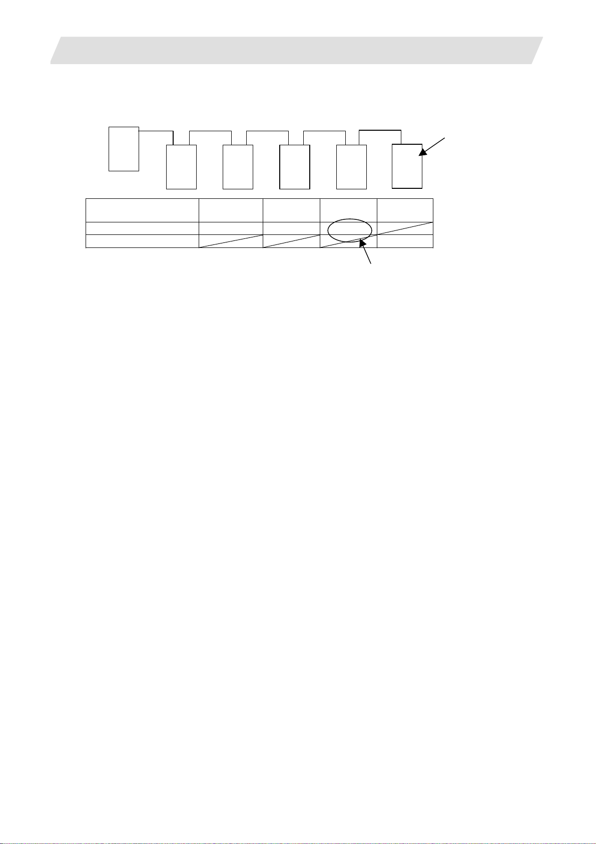
Operation in each mode
Operation
mode
Memory/MDI Movement command invalid
(Note 1) (Including G28)
JOG feed Valid Valid
Rapid traverse Valid Valid
Handle Valid Valid
Step Valid Valid
Zero point return Starting not possible (Note 2) Starting possible
(Note 1) The program error (P430) will occur.
(Note 2) If the axis before the absolute position establish is started, the error "M01 OPERATION ERROR
0024" will occur.
(This mode is valid for an axis for which the absolute position has been est ablished.)
Selecting the zero point initialization method
Select the zero point initialization method with the following parameter.
#2049 type 1: Dogless type Machine end stopper method
2: Dogless type Marked point alignment method
3: Dog type
4: Dogless type Marked point alignment method II
Absolute position detection method
Dogless-type Dog-type
Movement command invalid
(Note 1) (G28 is valid)
I - 32
Page 47

3. Setup Details
Dogless-type zero point initialization
The zero point is initialized using the ABS POSITION SET screen and JOG or handle.
The operation methods differ according to the zero point initialization method. Re fer to the Instructio n
Manual for details.
(1) Machine end stopper method
The machine end stopper method includes the manual initialization and automatic initialization
methods.
(a) Manual initialization
Dog-type zero point initialization
With this method, the axis is pushed against the machine end stopper using handle or JOG.
(b) Automatic initialization
With this method, the axis is pushed against the machine end stopper, and can be used when the
"INIT-SET" mode is selected. This method has the following features compared to the manual
initialization method.
・The axis is pushed with the same conditions (feedrate, distance) each time, so inconsistencies in
the zero point position can be reduced.
・Part of the operations is automated to simplify the zero point initialization.
(2) Marked point alignment method
With this method, the axis is aligned to the machine's basic point (marked point) using handle or
JOG. The first grid point where the axis reaches upon retraction in the opposite direction after
alignment to the marked point is regarded as the basic point.
(3) Marked point alignment method II
With this method, the axis is aligned to the machine's basic point (marked point) using handle or
JOG. The machine’s basic position (marked point) is regarded a s th e basi c poi nt.
By executing dog-type reference position return with the manual reference position return mode or
automatic reference position return command (G28), the zero point will be initialized.
3.9 Absolute Position Detection System
I - 33
Page 48

3. Setup Details
3.10 Auxiliary Axis Operation
3.10 Auxiliary Axis Operation
Auxiliary axis absolute position initial setting and test run are carried out on the auxiliary axis test screen.
In this section, only the outline is introduced. Refer to the Instruction Manual and "MR-J2-CT Specifications
and Instruction Manual (BNP-B3944)" for details.
Also, refer to "13. Auxiliary Axis Parameter" in "III Parameter" for details on the auxiliary axis parameters.
I -
34
Page 49

3. Setup Details
3.10 Auxiliary Axis Operation
3.10.1 Preparations
Before the screen is switched to auxiliary axis test screen, prepare the following things.
(1) Parameter settings
Set the following parameters.
No. Name Setting details
50102 Cont2
50120 ABS
Type
Control
parameter 2
Absolute
position
detection
parameter
bit7 = 1 (Absolute position detection)
Turn the NC power ON again after this parameter is set.
The alarm "Z70 Abs data error" occurs after the power
(Note)
ON again.
bit1/bit2 : Select the absolute position detection method.
Method bit2 bit1 Details
Dog-type method
Mechanical end
stopper method
Marked point
alignment method
When bit1 is "1", dog-type method is selected regardless of
(Note)
(Note)
0 0 This decides the basic point by
1 0 This decides the basic point by
1 This decides the reference
position by the near point dog.
pushing an axis to machine end
etc. when the torque (current)
limit is set.
aligning an axis to machine origin
point.
bit2 setting.
bit3 : Select the electrical basic position direction at marked point
alignment method.
Direction bit3
Electrical basic position direction + 0
Electrical basic position direction - 1
(2) Release servo OFF/interlock for auxiliary axis.
(3) Turn J2CT operation adjustment mode valid signal (R9998/bit0) ON.
I -
35
Page 50

3. Setup Details
3.10 Auxiliary Axis Operation
3.10.2 Absolute Position Initial Setting
The coordinate system is established and operation is enabled when the absolute position is initially set.
Carry this out when absolute position is not established.
Refer to the Instruction Manual for detailed operations.
3.10.3 Test Operation
Disconnect the auxiliary axis control from PLC and startup in a forward/reverse run by menu operation to
carry out a test operation.
Refer to the Instruction Manual for detailed operations.
I -
36
Page 51

3. Setup Details
3.10 Auxiliary Axis Operation
3.10.4 PLC device
Devices that are used for auxiliary axis operation adjustment and control are as follows.
Refer to "MR-J2-CT Specifications and Instruction Manual (BNP-B3944)" for details.
(1) Operation adjustment mode
Device No.
bit
R9998 bit0 J2CT Operation adjustment mode valid (Common for all axes)
R9948 bit0 J2CT 1st axis in operation adjustment mode
bit1 J2CT 2nd axis in ope ration adjustment mode
bit2 J2CT 3rd axis in operation adjustment mode
bit3 J2CT 4th axis in operation adjustment mode
(2) Auxiliary axis control command
Signal name J2CT
Abbrev. CTCM4 CTCM3 CTCM2 CTCM1 CTCML CTCMH
J2CT
1st axis
J2CT
2nd axis
J2CT
3rd axis
J2CT
4th axis
(a) CTCM1 (J2CT Control command 1)
bit Details
0 *SVF Servo OFF
1 QEMG PLC emergency stop
2 *PRT1 Data protect
3 MRST MC reset
4 *IT+ Interlock +
5 *IT- Interlock 6 RDF Ready OFF
7 H Handle mode
8 AUT Automatic operation mode
9 MAN Manual operation mode
A J Jog mode
B ZRN Reference position mode
C
D AZS Zero point initialization mode
E ZST Basic position set
F S Incremental mode
Abbrev. Signal name
J2CT
Control
command L
Control
command 4
J2CT
Control
command 3
J2CT
Control
command 2
J2CT
Control
command 1
R9950 R9951 R9952 R9953 R9954 R9955
R9956 R9957 R9958 R9959 R9960 R9961
R9962 R9963 R9964 R9965 R9966 R9967
R9968 R9969 R9970 R9971 R9972 R9973
(b) CTCM2 (J2CT Control command 2)
bit Details
0 ST Operation start
1 DIR Rotation direction
2 STS Arbitrary point feed command valid
3 PUS Stopper positioning command valid
4 MP1 Incremental feed magnification 1
5 MP2 Incremental feed magnification 2
6 PR1 Operation parameter selection1
7 PR2 Operation parameter selection 2
8
9
A
B
C
D
E
F
J2CT
Control
command H
I -
37
Page 52

3. Setup Details
(c) CTCM3 (J2CT Control command 3)
bit Details
0 ST1 Station selection 1
1 ST2 Station selection 2
2 ST4 Station selection 4
3 ST8 Station selection 8
4 ST16 Station selection 16
5 ST32 Station selection 32
6 ST64 Station selection 64
7 ST128 Station selection 128
8 ST256 Station selection 256
9
A
B
C
D
E
F
(e) CTCML, CTCMH (J2CT Control command L, control command H)
CTCML
Command position during arbitrary point feed command valid (32bit)
CTCMH
(b) CTCM4 (J2CT Control command 4)
bit Details
0 OVR1 Speed override 1
1 OVR2 Speed override 2
2 OVR4 Speed override 4
3 OVR8 Speed override 8
4 OVR16 Speed override 16
5 OVR32 Speed override 32
6 OVR64 Speed override 64
7 OVR Speed override valid
8
9
A
B
C
D
E
F
3.10 Auxiliary Axis Operation
I -
38
Page 53

3. Setup Details
(3) Auxiliary axis status
Signal name J2CT
Abbrev. CTST4 CTST3 CTST2 CTST1
J2CT
1st axis
J2CT
2nd axis
J2CT
3rd axis
J2CT
4th axis
(a) CTST1 (J2CT Status 1)
bit Details
0 RDY Servo ready
1 INP In-position
2 SMZ Smoothing zero
3 AX1 Axis selection output
4 MVP In axis movement +
5 MVN In axis movement 6 TLQ In torque limit
7 ADJ Adjusting machine
8 ZP Reference position reached
9 RST In reset
A HO In handle mode
B MA Controller preparation complete
C SA Servo preparation complete
D JSTA Automatic set position reached
E JST Set position reached
F NEAR Near set position
3.10 Auxiliary Axis Operation
Machine position
Status 4
J2CT
Status 3
J2CT
Status 2
J2CT
Status 1
R9900 R9901 R9902 R9903 R9904,
R9905
R9906 R9907 R9908 R9909 R9910,
R9911
R9912 R9913 R9914 R9915 R9916,
R9917
R9918 R9919 R9920 R9921 R9922,
R9923
(b) CTST2 (J2CT Status 2)
bit Details
0 AUTO In automatic operation mode
1 MANO In manual operation mode
2 JO In jog mode
3 ARNN In reference position return
4 ZRNO In reference position return mode
5 DOG Near-point dog
6 AZSO In zero point initialization mode
7 SO In incremental mode
8 AL1 Alarm 1
9 AL2 Alarm 2
A AL4 Alarm 4
B BAT Battery voltage drop
C ABS
Absolute position power shutoff
movement over
D ZSN Absolute position loss
E ZSF Initial setting completed
F ZSE Initial setting error completed
I -
39
Page 54

3. Setup Details
3.10 Auxiliary Axis Operation
(c) CTST3 (Status 3)
bit Details
0 STO1 Station position 1
1 STO2 Station position 2
2 STO4 Station position 4
3 STO8 Station position 8
4 STO16 Station position 16
5 STO32 Station position 32
6 STO64 Station position 64
7 STO128 Station position 128
8 STO256 Station position 256
9
A
B
C
D
E
F
(d) CTST4 (J2CT Status 4)
bit Details
0 PSW1 Position switch 1
1 PSW2 Position switch 2
2 PSW3 Position switch 3
3 PSW4 Position switch 4
4 PSW5 Position switch 5
5 PSW6 Position switch 6
6 PSW7 Position switch 7
7 PSW8 Position switch 8
8 PMV In positioning operation
9 PFN Positioning complete
A PSI In stopper
B
C
D
E
F
3.10.5 Notes
(1) Do not turn "Auto operation "start" command signal (ST) " ON during Ope. test mode.
(2) NC does not retain auxiliary axis parameters. Parameters are retained at the auxiliary axis side.
(3) Auxiliary axis emergency stop has to be commanded by PLC interface.
(4) NC axis handle movement is invalid during auxiliary axis handle mode.
(5) If the screen shifts other screen, the auxiliary axis mode (Ope. test mode, Absolute posn set) is held.
Thus, the axis does not stop even if the axis is rotating.
I -
40
Page 55

3. Setup Details
3.11 Data Sampling
3.11 Data Sampling
NC data sampling function allows a sampling of NC internal data (speed output from NC to drive unit,
feedback data from drive unit, etc.) so that the data is output as text data.
Item Specifications
Sampling cycle 700 Series
1.7ms x setting value
70 Series (type A)
1.7ms x setting value
70 Series (type B)
3.5ms x setting value
Number of sampled axes 700 Series
Servo axis : 1 to 16 axes
Spindle : 1 to 4 axes
70 Series
Servo axis : 1 to 7 axes
Spindle : 1 to 3 axes
Number of sampled
channels
Sampling data size 700 Series
● Parameter output is not executed for the data set with this function.
● The state returns to "Sampling stop" when the power is turned ON.
Refer to the "diagnosis data collection setting screen" section in the Instruction Manual for detailed
operations.
1 to 8 points
Maximum 1,310,720 points
70 Series
Maximum 655,360 points
(Note 1) This is the entire data size. The data size per channel will
decrease when the number of sampled channels
increases.
(Note 2) If the open DRAM memory is insufficient, the maximum
data size will decrease.
3.12 Data backup
With this function, system data (program, parameter, R register, etc.), ladder (user PLC program ), APLC data
can be backed up/restored.
Refer to the "all backup screen" section in the Instruction Manual for detailed operations.
I -
41
Page 56

3. Setup Details
3.13 M70 SETUP INSTALLER
Install the following data with M70 SETUP INSTALLER.
(1) Language data
(2) Custom data
• Custom screen
• PLC alarm guidance
(3) Custom startup screen
Use CF card to carry out the installation.
3.13.1 Compatible Data and CF Card Folder Configuration
(1) Compatible data with M70 SETUP INSTALLER
Type Data Details Remarks
lang0_xxx.bin Language data (for FROM) Language data
lang1_xxx.bin Language data
(for expansion FROM)
Custom data
Custom screen
module
config.ini A setting file to register custom
customdef.ini A setting file to register custom
customload.txt A setting file to register name
PLC alarm
guidance data
Custom startup
startupscreen.bmp A bitmap file to be displayed on
screen
Interpreter data and
object data
screen.
screen for the menus and
function buttons on the default
screen.
and load order of the object
data.
HTML files and JPEG files to
be displayed in the PLC alarm
guidance.
the initial screen when power is
turned ON.
3.13 M70 SETUP INSTALLER
Language
identification string
is shown instead of
xxx.
(ex. jpn: Japanese,
fra: french)
Color: 256 Colors
(8 bit)
Size: 640 * 440
I -
42
Page 57

3. Setup Details
A
A
3.13 M70 SETUP INSTALLER
(2) CF card folder configuration
Compatible data with M70 SETUP INSTALLER is stored in CF card with the folder configuration as
follows.
CF Card
Lang (language data folder)
0 (folder labeled by version)
lang0_jpn.bin (Japanese language data for FROM)
lang1_jpn.bin (Japanese language data for expansion FROM)
:
:
1 (folder labeled by version)
custom (custom data folder)
PLCAlarm (PLC alarm guidance folder)
PLCAlarm_0001_jpn.htm (PLC alarm guidance data)
:
:
Custom screen modules
Setting files
startupscreen.bmp (bitmap data for custom startup screen)
Installer (installer folder)
installer.o (installer)
I -
43
Page 58

3. Setup Details
3.13.2 Operation Method
Starting up M70 SETUP INSTALLER
(1) Insert the CF card for M70 SETUP
INSTALLER into the front panel CF.
(2) Turn the power ON while pressing the
menu
.
3.13 M70 SETUP INSTALLER
Startup screen appears. A bleep sounds
after a while, and then the mode selection
screen for M70 SETUP INSTALLER
appears.
Keep pressing the menu
(Note)
until a bleep sounds.
I -
44
Page 59

3. Setup Details
Installing language data
(1) Press the menu key [Lang Pack] on the
mode selection screen.
•
The next language selection menu is displayed by pressing menu (Next menu >>).
(2) Select the language to install with the
menu key.
3.13 M70 SETUP INSTALLER
Language data installation screen appears.
The language selection menu is displayed.
The language currently installed is shown in
the “Installed Language” field.
The language selected is shown in the “Now
Selected Language” field.
•
To change the language already selected, press the menu key [Clear] and select again.
•
The 2nd language can be selected when the expansion FROM is p rovided. (Cursor m oves to
the “2nd” field after the 1st language has been selected.)
(3) Press the menu key [Install].
A confirmation message appears.
(4) Press the menu key [Yes].
A message appears after the installation has
completed.
•
Pressing the menu key [No] returns to the language selection menu.
•
Do not turn the power OFF during the installation of language data.
Pressing the menu
(Note)
(<< Cancel) returns to the mode selection screen.
I -
45
Page 60

3. Setup Details
Installing custom data
(1) Press the menu key [Custom Data] on
the mode selection screen.
(2) Press the menu key [Install].
3.13 M70 SETUP INSTALLER
Custom data installation screen appears.
A confirmation message appears.
(3) Press the menu key [Yes].
•
Pressing the menu key [No] returns to the first menu.
•
Do not turn the power OFF during the installation of custom data.
Uninstalling custom data
(1) Press the menu key [Uninst] on the
custom data installation screen.
A message appears after the installation has
completed.
A confirmation message appears.
(2) Press the menu key [Yes].
A message appears after the installation has
completed.
•
Pressing the menu key [No] returns to the first menu.
•
Do not turn the power OFF during the uninstallation of custom data.
Pressing the menu
(Note)
(<< Cancel) returns to the mode selection screen.
I -
46
Page 61

3. Setup Details
Installing custom startup screen
(1) Press the menu key [Custom Startup] on
the initial screen of M70 SETUP
INSTALLER.
(2) Press the menu key [Install].
3.13 M70 SETUP INSTALLER
Custom Startup Screen Install screen
appears.
A confirmation message appears.
(3) Press the menu key [Yes].
A message appears after the installation has
completed.
•
Pressing the menu key [No] returns to the first menu.
•
Do not turn the power OFF during the installation of custom startup screen.
I -
47
Page 62

3. Setup Details
Uninstalling custom startup screen
(1) Press the menu key [Uninst] on the
Custom Startup Screen Install screen.
(2) Press the menu key [Yes].
•
Pressing the menu key [No] returns to the first menu.
•
Do not turn the power OFF during the uninstallation of custom startup screen.
Pressing the menu
(Note)
3.13 M70 SETUP INSTALLER
A confirmation message appears.
A message appears after the installation has
completed.
(<< Cancel) returns to the mode selection screen.
I -
48
Page 63

3. Setup Details
3.13 M70 SETUP INSTALLER
3.13.3 List of Error Messages
Message Details
The 1st language is not selected. The first language has not been selected at the
installation of language pack.
Specify the first language again.
The same language is selected. The same language has been selected as both first and
second language at the installation of language pack.
Specify the language again.
The selected language does not exist.(1st) The language data, selected as the 1st language at the
installation of language pack, does not exist .
Ensure that the language data has been stored in the
CF card, and that the version of the data is appropriate.
The selected language does not exist.(2nd) The language data, sele cted as the 2nd langu age at the
installation of language pack, does not exist.
Ensure that the language data has been stored in the
CF card, and that the version of the data is appropriate.
The custom data does not exist. The “custom” folder does not exist in the CF card.
Check the stored data in the CF card.
The file startupscreen.bmp" does not exist." The "startupscreen.bmp" file does not exist in the CF
card.
Check the stored data in the CF card.
I -
49
Page 64

4. 700 Series H/W Replacement Methods
4.1 Durable Parts
4. 700 Series H/W Replacement Methods
4.1 Durable Parts
4.1.1 Control unit battery
All data, such as the parameters and machining programs that need to be backed up when the power is
turned OFF, are saved by a lithium battery installed in the control unit's battery holder.
Battery Q6BAT BKO-C10811H03 (SANYO CR17335SE-R with
Mitsubishi specifications)
Battery cumulative data holding time 45,000 hours (At room temperature. The life will be shorter if
the temperature is high.))
(Note) Replace the battery when the alarm "Z52 Battery drop 0001" appears on the NC screen.
[Replacement procedures]
Always replace the battery with the control unit (machine) power turned OFF.
Complete the replacement within 30 minutes after turning the power OFF. (If the battery is not connected
within 30 minutes, the data being backed up might be destroyed.)
Battery life Approx. 5 years (from date of battery manufacture)
The internal data could be damaged if the alarm "Z52 Battery drop 0003" appears.
(1) Check that the machine power is turned OFF. (If the power is not OFF, turn it OFF.)
(2) Open the electric cabinet door, and confirm that the control unit LED, 7-segment display, etc., are all
OFF.
(3) Open the front cover of the control unit. Pull the right side of the front cover toward front.
(4) Pull the connector connected to the battery out from the BAT connector.
(5) Remove the battery from the battery holder.
(6) Fit the new battery into the battery holder.
(7) Insert the connector connected to the new battery into the BAT connector. Pay attention to the
connector orientation, being careful not to insert backwards.
(8) Close the front cover of the control unit. At this time, confirm that the cover i s closed by liste ning for th e
"click" sound when the latch catches.
(9) Close the door of the electric cabinet.
Front cover
BAT connector
Battery holder
Connector connected
to the battery
Battery
I - 50
Page 65

4. 700 Series H/W Replacement Methods
[Precautions for handling battery]
(1) Always replace the battery with the same type.
(2) Do not disassemble the battery.
(3) Do not place the battery in flames or water.
(4) Do not pressurize and deform the battery.
(5) This is a primary battery so do not charge it.
(6) Dispose of the spent battery as industrial waste.
4.1 Durable Parts
CAUTION
!
If the battery low warning is issued, save the machining programs, tool data and parameters in an
input/output device, and then replace the battery. When the battery alarm is issued, the machining
programs, tool data and parameters may be destroyed. Reload the data after replacing the battery.
Do not short circuit, charge, overheat, incinerate or disassemble the battery.
Dispose the spent battery according to the local laws.
I - 51
Page 66

4. 700 Series H/W Replacement Methods
4.1 Durable Parts
4.1.2 Cooling fan for control unit
Type : 109P0412H731
Life : 60,000 hours (When the rotary speed decreased 30% less than the initial values)
Cooling fan (for control unit) life is estimated on the assumption that it is used under 60°C
environment. Keep in mind that the value above is not a guaranteed value.
[Replacement procedures]
Always replace the cooling fan with the control unit (machine) power turned OFF.
(1) Check that the machine power is turned OFF. (If the power is not OFF, turn it OFF.)
(2) Open the electric cabinet door.
(3) Remove the fan cover on the top center of the control unit. (Remove the fan cover by pushing up the
front tab.)
(4) Pull out the cooling fan from the control unit cooling fan housing.
(5) Pull the connector connected to the cooling fan out from the control unit PCB.
(6) Replace the cooling fan with the new one. Insert the connector connected to the new cooling fan into
the control unit PCB.
(7) Put the cooling fan into the control section cooling fan housing. (Be sure the label side is on the top.)
(8) Arrange the cooling fan wiring neatly in the control unit cooling fan housing.
(9) Install the fan cover. (First install the back tabs in the control unit. Then install the front tabs in the
control unit.)
(10) Confirm that all the cables are correctly connected and close the electric cabinet door.
Front tab
Fan cover
Cooling fan
Back
tab
Control unit
CAUTION
!
Do not replace the control unit while the power is ON.
Collect and dispose of the spent cooling fan according to the local laws.
I - 52
Page 67

4. 700 Series H/W Replacement Methods
4.1 Durable Parts
4.1.3 Cooling fan for display unit (XP terminal)
Type : MMF-06D24DS-RP3
Life : 50,000 hours (When the rotary speed decreased 20% less than the initial values)
Cooling fan (for display unit) life is estimated on the assumption that it is used under 60°C
environment. Keep in mind that the value above is not a guaranteed value.
[Replacement procedures]
Always replace the cooling fan for display unit with the control unit (machine) power turned OFF.
(1) Check that the machine power is turned OFF. (If the power is not OFF, turn it OFF.)
(2) Open the electric cabinet door.
(3) Remove the fan cover of cooling fan housing (2 parts) that is installed to PCB on back of display unit.
(Remove the fan cover by pushing up the front tab.)
(4) Pull out the cooling fan from the control unit cooling fan housing.
(5) Pull the connector connected to the cooling fan out from the control unit PCB.
(6) Replace the cooling fan with the new one. Insert the connector connected to the new cooling fan into
the control unit PCB.
(7) Put the cooling fan into the control section cooling fan housing. (Be sure the label side is on the top.)
(8) Arrange the cooling fan wiring neatly in the control unit cooling fan housing.
(9) Install the fan cover.
(10) Confirm that all the cables are correctly connected and close the electric cabinet door.
Tab
Fan cover
Cooling fan
Cooling fan
housing
CAUTION
!
Do not replace the control unit while the power is ON.
Collect and dispose of the spent cooling fan according to the local laws.
I - 53
Page 68

4. 700 Series H/W Replacement Methods
4.1 Durable Parts
4.1.4 Backlight
● 8.4-type
LCD panel NL6448BC26-01 (NEC)
Inverter 65PWB31 (NEC)
Backlight for replacement 84LHS01 (NEC)
Backlight life 30,000 hours (Duration of time until luminance drops to 50% of the initial
value.)
● 10.4-type
LCD panel NL6448BC33-53, NL6448BC33-54 (NEC)
Inverter 104PW161 (NEC)
Backlight for replacement 104LHS35 (NEC)
Backlight life 50,000 hours (ambient temperature 25°C) (Duration of time until
luminance drops to 50% of the initial value.)
Backlight life is estimated on the assumption that it is used under 25°C environment. Keep in mind that the
value above is not a guaranteed value.
[Replacement procedures]
Always replace the backlight for LCD panel with the control unit (machine) power turned OFF.
(1) Check that the machine power is turned OFF. (If the power is not OFF, turn it OFF.)
(2) Open the electric cabinet door.
(3) Pull the connector connected to the backlight out from the backlight power supply PCB. (For 8.4 inch,
one each for top and bottom; for 10.4 inch, one for top.)
(4) Disconnect the menu key connector.
(5) Remove the escutcheon fixing screws (at 4 places) and take the escutcheon off.
(6) Pull out the backlight installed on the left side of the LCD panel. (The backlights have locking claws on
the front. Hold these claws down while pulling the backlight out.)
(7) Insert the new backlight into the upper and lower sections at the left end of the LCD panel. (Press in
until the locking claws click.)
(8) Mount the escutcheon with 2 fixing screws (1 each for the upper and lower sections of the left end).
(9) Connect the backlight connection connector to the backlight power supply PCB.
(10) Confirm that all the cables are correctly connected and close the electric cabinet door.
(11) Connect the menu key connector.
[Precautions for using LCD panel]
(1) Depending on the ambient temperature, response time, brightness and color may differ.
(2) Depending on the display contents, nonuniformity of brightness, flickers and streaks may be observed
on LCD display.
(3) Because cold cathod-tube is used for LCD display, optical characteristics (nonuniformity of brightness
and display) change according to the operation time. (Especially in low temperature.)
(4) Screen display color may be differed depending on the angle to view it.
I - 54
Page 69

4. 700 Series H/W Replacement Methods
CAUTION
!
Do not replace the backlight while the power is ON.
Dispose the replaced backlight according to the local laws.
Do not touch the backlight while the power is ON. Failure to observe this could result in electric
shocks due to high voltage.
Do not touch the backlight while the LCD panel is in use. Failure to observe this could result in burns.
Do not apply impact or pressure on the LCD panel or backlight. Failure to observe this could result in
breakage as they are made of glass.
[8.4-type display unit]
4.1 Durable Parts
Escutcheon
Menu key connector
LCD panel
Backlight
Escutcheon
Menu key connector
I - 55
Page 70

4. 700 Series H/W Replacement Methods
[10.4-type display unit]
4.1 Durable Parts
Control unit fittings
Escutcheon
Menu key connector
Escutcheon
Menu key connector
LCD panel
Backlight
I - 56
Page 71

4. 700 Series H/W Replacement Methods
4.2 Unit
4.2 Unit
4.2.1 Control Unit
[Replacement procedures]
Always replace the control unit with the control unit (machine) power turned OFF.
(1) Check that the machine power is turned OFF. (If the power is not OFF, turn it OFF.)
(2) Open the electric cabinet door.
(3) Disconnect all the cables connected to the control unit.
(4) Remove the screws fixing the control unit, and remove the control unit from the control unit installation
fitting. (Loosen the two lower fixing screws first, and then remove one upper fixing screw while
supporting the control unit with a hand. Then lift the control unit upward and take it off. The two lower
fixing screws do not need to be removed.)
(5) Replace with a new control unit, and fix the control unit onto control unit installation fitting with the fixing
screws.
(6) Connect all the cables back to the control unit. (Connect the cables to the designated connectors.)
(7) Confirm that all the cables are correctly connected and close the electric cabinet door.
Fixing screws (3)
CAUTION
!
Incorrect connections may damage the devices, so connect the cables to the specified connectors.
Do not replace the control unit while the power is ON.
Do not connect or disconnect the connection cables between each unit while the power is ON.
I - 57
Page 72

4. 700 Series H/W Replacement Methods
(Note) Wire the control unit optical cable as shown below.
Control unit
Optical communication cable
(section without reinforced sheath):
Bending radius: 25mm or more
Optical communication cable
(section with reinforced sheath):
Bending radius: 50mm or more
4.2 Unit
Recommended clamp material
CKN-13SP
KITAGAWA INDUSTRIES
- 58
I
Page 73

4. 700 Series H/W Replacement Methods
4.2 Unit
4.2.2 Display Unit
[Replacement procedures]
Always replace the display unit with the control unit (machine) power turned OFF.
(1) Check that the machine power is turned OFF. (If the power is not OFF, turn it OFF.)
(2) Open the electric cabinet door.
(3) Disconnect all the cables connected to the display unit.
(4) Remove the screws fixing the display unit (at 4 places) and take the display unit off.
(5) Replace with a new display unit, and fix the display unit with the fixing screws.
(6) Connect all the cables connected to the display unit. (Connect the cables to the designated
connectors.)
(7) Confirm that all the cables are correctly connected and close the electric cabinet door.
Fixing screws (4)
CAUTION
!
Incorrect connections may damage the devices, so connect the cables to the specified connectors.
Do not replace the display unit while the power is ON.
Do not connect or disconnect the connection cables between each unit while the power is ON.
- 59
I
Page 74

4. 700 Series H/W Replacement Methods
4.2 Unit
4.2.3 Keyboard unit
[Replacement procedures]
Always replace the keyboard unit with the control unit (machine) power turned OFF.
(1) Check that the machine power is turned OFF. (If the power is not OFF, turn it OFF.)
(2) Open the electric cabinet door.
(3) Disconnect all the cables connected to the keyboard unit.
(4) Remove the screws fixing the keyboard unit and take the keyboard unit off.
(5) Replace with a new keyboard unit, and fix the keyboard unit with the fixing screws.
(6) Connect all the cables connected to the keyboard unit. (Connect the cables to the designated
connectors.)
(7) Confirm that all the cables are correctly connected and close the electric cabinet door.
CAUTION
!
Incorrect connections may damage the devices, so connect the cables to the specified connectors.
Do not replace the keyboard unit while the power is ON.
Do not connect or disconnect the connection cables between each unit while the power is ON.
- 60
I
Page 75

4. 700 Series H/W Replacement Methods
[8.4-type Keyboard unit]
Fixing screws (4)
4.2 Unit
[10.4-type Keyboard unit]
Fixing screws (4)
- 61
I
Page 76

4. 700 Series H/W Replacement Methods
4.2.4 DX Unit
[Replacement procedures]
Always replace the DX unit with the control unit (machine) power turned OFF.
(1) Check that the machine power is turned OFF. (If the power is not OFF, turn it OFF.)
(2) Open the electric cabinet door.
(3) Disconnect all the cables connected to the DX unit.
(4) Remove the screws fixing the DX unit and take the DX unit off.
(5) Replace with a new DX unit, and fix the DX unit onto the control unit with the fixing screws.
(Fix so that the DX unit connector slot is placed at the lower part.)
(6) Connect all the cables connected to the DX unit. (Connect the cables to the designated connectors.)
(7) Confirm that all the cables are correctly connected and close the electric cabinet door.
4.2 Unit
Fixing screws (4)
Connector slot
CAUTION
!
Incorrect connections may damage the devices, so connect the cables to the specified connectors.
Do not replace the DX unit while the power is ON.
Do not connect or disconnect the connection cables between each unit while the power is ON.
- 62
I
Page 77

4. 700 Series H/W Replacement Methods
4.2.5 Hard Disk Unit
Hard disk unit life: 5 years or 20,000 hours of power ON, whichever comes first .
[Replacement procedures]
Always replace the hard disk unit with the control unit (machine) power turned OFF.
(1) Check that the machine power is turned OFF. (If the power is not OFF, turn it OFF.)
(2) Open the electric cabinet door.
(3) Disconnect all F140 cables connected to the hard disk in the hard disk unit.
(Always disconnect F140 cables holding the front and back of the hard disk securely with fingers.)
(4) Remove the screws fixing the hard disk unit (2 at upper part, 1 at lower pa rt) and take the hard disk unit
off.
(5) Replace with a new hard disk unit, and fix the hard disk unit with the fixing screws.
(6) Connect F140 cables to the hard disk in the hard disk unit.
(Always connect F140 cables in the correct connector direction fixing the bottom of the hard disk with
fingers.)
(7) Confirm that all the cables are correctly connected and close the electric cabinet door.
4.2 Unit
Fixing screws (2)
(Note) When mounting the hard disk unit, face the cable lead-out side directly straight up, and mount within
±15°.
15°
15°
CAUTION
!
Incorrect connections may damage the devices, so connect the cables to the specified connectors.
Do not replace the hard disk unit while the power is ON.
Dispose of the replaced hard disk unit according to the local laws.
Hard disk unit is a precision device, so do not drop or apply strong impacts on it.
- 63
I
Page 78

4. 700 Series H/W Replacement Methods
4.3 Compact Flash
4.3 Compact Flash
4.3.1 Control Unit Compact Flash
[Replacement procedures]
Always replace the compact flash with the control unit (machine) power turned OFF.
(1) Check that the machine power is turned OFF. (If the power is not OFF, turn it OFF.)
(2) Open the electric cabinet door, and confirm that the control unit LED, 7-segment display, etc., are all
OFF.
(3) Open the front cover of the control unit.
(4) Press the eject lever twice to eject the compact flash.
(5) Insert the new compact flash. (The surface is faced on the observers' right.)
(6) Close the front cover of the control unit. At this time, confirm that the cover i s closed by liste ning for th e
"click" sound when the latch catches.
(7) Close the electric cabinet door.
Front
cover
Eject lever
Compact flash slot
Compact flash
(Note 1) There may be a compatibility problem with commercially available compact flash memory,
resulting in mulfunction.
- 64
I
Page 79

4. 700 Series H/W Replacement Methods
4.4 IC card
4.4.1 Front IC Card
[Card insertion procedures]
(1) Open the card slot door located on the display unit right end.
(2) Insert the IC card. (The surface is faced on the observers' right.)
[Card ejecting procedures]
(1) Open the card slot door located on the display unit right end.
(2) Press the eject lever twice to eject the IC card.
Eject lever
4.4 IC Card
IC card
(Note 1) Do not eject an IC card during the data reading/writing.
(Note 2) There may be a compatibility problem between devices a commercially available IC card, so
illegal operations may occur.
- 65
I
Page 80

5. 70 Series H/W Replacement Methods
y
5.1 Durable Parts
5. 70 Series H/W Replacement Methods
5.1 Durable Parts
5.1.1 Control unit battery
All data, such as the parameters and machining programs that need to be backed up when the power is
turned OFF, are saved by a lithium battery installed in the control unit's battery holder.
Battery Q6BAT BKO-C10811H03 (SANYO CR17335SE-R with
Mitsubishi specifications)
Battery cumulative data holding time 45,000 hours (At room temperature. The life will be shorter if
the temperature is high.))
(Note) Replace the battery when the alarm "Z52 Battery drop 0001" appears on the NC screen.
[Replacement procedures]
Always replace the battery with the control unit (machine) power turned OFF.
Complete the replacement within 30 minutes after turning the power OFF. (If the battery is not connected
within 30 minutes, the data being backed up might be destroyed.)
Battery life Approx. 5 years (from date of battery manufacture)
The internal data could be damaged if the alarm "Z52 Battery drop 0003" appears.
(1) Check that the machine power is turned OFF. (If the power is not OFF, turn it OFF.)
(2) Confirm that the control unit LED, 7-segment display, etc., are all OFF.
(3) Open the battery cover of the control unit. Pull the right side of the battery cover toward front.
(4) Pull the connector connected to the battery out from the BAT connector.
(5) Remove the battery from the battery holder.
(6) Fit the new battery into the battery holder.
(7) Insert the connector connected to the new battery into the BAT connector. Pay attention to the
connector orientation, being careful not to insert backwards.
(8) Close the front cover of the control unit. At this time, confirm that the cover i s closed by liste ning for th e
"click" sound when the latch catches.
Battery cover
Batter
Battery holder
BAT connector
I - 66
Page 81

5. 70 Series H/W Replacement Methods
[Precautions for handling battery]
(1) Always replace the battery with the same type.
(2) Do not disassemble the battery.
(3) Do not place the battery in flames or water.
(4) Do not pressurize and deform the battery.
(5) This is a primary battery so do not charge it.
(6) Dispose of the spent battery as industrial waste.
5.1 Durable Parts
CAUTION
!
If the battery low warning is issued, save the machining programs, tool data and parameters in an
input/output device, and then replace the battery. When the battery alarm is issued, the machining
programs, tool data and parameters may be destroyed. Reload the data after replacing the battery.
Do not short circuit, charge, overheat, incinerate or disassemble the battery.
Dispose the spent battery according to the local laws.
I - 67
Page 82

5. 70 Series H/W Replacement Methods
5.1 Durable Parts
5.1.2 Backlight
● 8.4-type
Inverter 65PWB31
Backlight for replacement 84LHS01
Backlight life 50,000 hours (Duration of time until luminance drops to 50% of the initial
value.)
● 10.4-type
Inverter 104PW161
Backlight for replacement 104LHS35
Backlight life 50,000 hours (ambient temperature 25°C) (Duration of time until
luminance drops to 50% of the initial value.)
Backlight life is estimated on the assumption that it is used under 25°C environment. Keep in mind that the
value above is not a guaranteed value.
[Replacement procedures]
Always replace the backlight for LCD panel with the control unit (machine) power turned OFF.
(1) Check that the machine power is turned OFF. (If the power is not OFF, turn it OFF.)
(2) Pull the connector connected to the backlight out from the backlight inverter (one for top).
(3) Disconnect the MENU connector.
(4) Remove the escutcheon fixing screws (at 4 places) and take the escutcheon off.
(5) Pull out the backlight installed on the left side of the LCD panel. (The backlights have locking claws on
the front. Hold these claws down while pulling the backlight out.)
(6) Insert the new backlight into the upper and lower sections at the left end of the LCD panel. (Press in
until the locking claws click.)
(7) Mount the escutcheon with 4 fixing screws (1 each for 4 sections).
(8) Connect the backlight connection connector to the backlight inverter.
(9) Confirm that all the cables are correctly connected and close the electric cabinet door.
(10) Connect the MENU connector.
[Precautions for using LCD panel]
(1) Depending on the ambient temperature, response time, brightness and color may differ.
(2) Depending on the display contents, nonuniformity of brightness, flickers and streaks may be observed
on LCD display.
(3) Because cold cathod-tube is used for LCD display, optical characteristics (nonuniformity of brightness
and display) change according to the operation time. (Especially in low temperature.)
(4) Screen display color may be differed depending on the angle to view it.
I - 68
Page 83

5. 70 Series H/W Replacement Methods
CAUTION
!
Do not replace the backlight while the power is ON.
Dispose the replaced backlight according to the local laws.
Do not touch the backlight while the power is ON. Failure to observe this could result in electric
shocks due to high voltage.
Do not touch the backlight while the LCD panel is in use. Failure to observe this could result in burns.
Do not apply impact or pressure on the LCD panel or backlight. Failure to observe this could result in
breakage as they are made of glass.
[8.4-type/10.4-type display unit]
Backlight connector
5.1 Durable Parts
MENU connector
Backlight inverter
Backlight
I - 69
Page 84

5. 70 Series H/W Replacement Methods
5.2 Unit
5.2 Unit
5.2.1 Control Unit
[Replacement procedures]
Always replace the control unit with the control unit (machine) power turned OFF.
(1) Check that the machine power is turned OFF. (If the power is not OFF, turn it OFF.)
(2) Disconnect all the external cables connected to the control unit.
(3) Remove all the internal cables connected to the control unit. (MENU/INV/LCD connector)
(Note) Open the battery cover to remove LCD connector.
(4) Remove the screws fixing the control unit, and remove the control unit from the control unit installation
fitting. (Loosen the two lower fixing screws first, and then remove one upper fixing screw while
supporting the control unit with a hand. Then lift the control unit upward and take it off. The two lower
fixing screws do not need to be removed.)
(5) Replace with a new control unit, and fix the control unit onto control unit installation fitting with the fixing
screws.
(6) Connect all the cables back to the control unit. (Connect the cables to the designated connectors.)
(7) Confirm that all the cables are correctly connected and close the electric cabinet door.
INV connector
LCD connector
Battery cover
MENU connector
CAUTION
!
Incorrect connections may damage the devices, so connect the cables to the specified connectors.
Do not replace the control unit while the power is ON.
Do not connect or disconnect the connection cables between each unit while the power is ON.
I - 70
Page 85

5. 70 Series H/W Replacement Methods
(Note) Wire the control unit optical cable as shown below.
Control unit
Recommended clamp material
CKN-13SP
KITAGAWA INDUSTRIES
Optical communication cable
(section without reinforced sheath):
Bending radius: 30mm or more
5.2 Unit
- 71
I
Page 86

5. 70 Series H/W Replacement Methods
5.2 Unit
5.2.2 Display Unit
[Replacement procedures]
Always replace the display unit with the control unit (machine) power turned OFF.
(1) Check that the machine power is turned OFF. (If the power is not OFF, turn it OFF.)
(2) Open the electric cabinet door.
(3) Disconnect all the cables connected to the display unit.
(4) Remove the screws fixing the display unit (at 4 places) and take the display unit off.
(5) Replace with a new display unit, and fix the display unit with the fixing screws.
(6) Connect all the cables connected to the display unit. (Connect the cables to the designated
connectors.)
(7) Confirm that all the cables are correctly connected and close the electric cabinet door.
Fixing screws (4)
CAUTION
!
Incorrect connections may damage the devices, so connect the cables to the specified connectors.
Do not replace the display unit while the power is ON.
Do not connect or disconnect the connection cables between each unit while the power is ON.
- 72
I
Page 87

5. 70 Series H/W Replacement Methods
5.2 Unit
5.2.3 Keyboard unit
[Replacement procedures]
Always replace the keyboard unit with the control unit (machine) power turned OFF.
(1) Check that the machine power is turned OFF. (If the power is not OFF, turn it OFF.)
(2) Open the electric cabinet door.
(3) Disconnect all the cables connected to the keyboard unit.
(4) Remove the screws fixing the keyboard unit and take the keyboard unit off.
(5) Replace with a new keyboard unit, and fix the keyboard unit with the fixing screws.
(6) Connect all the cables connected to the keyboard unit. (Connect the cables to the designated
connectors.)
(7) Confirm that all the cables are correctly connected and close the electric cabinet door.
CAUTION
!
Incorrect connections may damage the devices, so connect the cables to the specified connectors.
Do not replace the keyboard unit while the power is ON.
Do not connect or disconnect the connection cables between each unit while the power is ON.
- 73
I
Page 88

5. 70 Series H/W Replacement Methods
[8.4-type Keyboard unit]
Fixing screws (4)
5.2 Unit
[10.4-type Keyboard unit]
Fixing screws (4)
- 74
I
Page 89

5. 70 Series H/W Replacement Methods
5.2.4 DX Unit
[Replacement procedures]
Always replace the DX unit with the control unit (machine) power turned OFF.
(1) Check that the machine power is turned OFF. (If the power is not OFF, turn it OFF.)
(2) Open the electric cabinet door.
(3) Disconnect all the cables connected to the DX unit.
(4) Remove the screws fixing the DX unit and take the DX unit off.
(5) Replace with a new DX unit, and fix the DX unit onto the control unit with the fixing screws.
(Fix so that the NCKB connector slot is placed at the lower part.)
(6) Connect all the cables connected to the DX unit. (Connect the cables to the designated connectors.)
NCKB cable can be easily inserted by fitting the Δ1st pin position with the connector.
(7) Confirm that all the cables are correctly connected and close the electric cabinet door.
5.2 Unit
Fixing screws (4)
NCKB connector
CAUTION
!
Incorrect connections may damage the devices, so connect the cables to the specified connectors.
Do not replace the DX unit while the power is ON.
Do not connect or disconnect the connection cables between each unit while the power is ON.
- 75
I
Page 90

5. 70 Series H/W Replacement Methods
5.3 Compact Flash
5.3.1 Front Compact Flash
[Card insertion procedures]
(1) Open the card slot door located on the display unit right end.
(2) Insert the compact flash. (The surface is faced on the observers' right.)
[Card ejecting procedures]
(1) Open the card slot door located on the display unit right end.
(2) Press the eject lever twice to eject the compact flash.
5.3 Compact Flash
Compact flash
Eject lever
(Note 1) Do not eject a compact flash during the data reading/writing.
(Note 2) There may be a compatibility problem with non-recommended compact flashes, which may lead
illegal operations.
- 76
I
Page 91

6. Cable
Y
6. Cable
If the cable is replaced without turning the power OFF, the normal unit or peripheral devices could be
damaged, and risks could be imposed.
Disconnect each cable with the following procedures.
(a) For the following type of connector, press the tabs with a thumb and forefinger in the direction of the
arrow, and pull the connector off.
(1) Press
(1) Press
(2) Pull
View from above
(2) Pull
(1) Press
(1) Press
(2) Pull
(2) Pull
CAUTION
!
Do not connect or disconnect the connection cables between each unit while the power is ON.
Do not pull the cables when connecting/disconnecting it.
I - 77
Page 92

6. Cable
(b) For a flat cable type connector with latches, open the latches in the directions of the arrows, and pull
the connector off.
(2) Pull
(1) Open
(c) For a flat cable type connector without latches, hold the connector with a thumb and forefinger, and pull
the connector off.
(2) Pull
(d) For the screw fixed type connector, loosen the two fixing screws, and pull the connector off.
(1) Hold with thumb and forefinger.
(1) Loosen
(1) Loosen
(2) Pull
CAUTION
!
Do not connect or disconnect the connection cables between each unit while the power is ON.
Do not pull the cables when connecting/disconnecting it.
(2) Pull
I - 78
Page 93

6. Cable
(e) For the optical cable connector, pull off while holding down the lock button.
(1) Press
(2) Pull
(f) For the Ethernet connector, pull off while holding down the locked latch.
(1) Press
(2) Pull
CAUTION
!
Do not connect or disconnect the connection cables between each unit while the power is ON.
Do not pull the cables when connecting/disconnecting it.
I - 79
Page 94

Page 95

II Explanation of Alarms
Page 96

Page 97

1. List of Alarms
1.1 Operation Alarms
1. List of Alarms
1.1 Operation Alarms
(The bold characters are the messages displayed on the screen.)
MUU Message {{{{
Error No.
Message
Class
(1) Class: M01 Operation error
Alarms occurring due to incorrect operation by the operator during NC operation and those by machine
trouble are displayed.
Error No. Details Remedy
0001 Dog overrun
When returning to the reference position‚ the
near-point detection limit switch did not stop
over the dog‚ but overran the dog.
0002 Some ax does not pass Z phase
One of the axes did not pass the Z-phase
during the initial reference position return after
the power was turned ON.
0003 R-pnt direction illegal
When manually returning to the reference
position‚ the return direction differs from the
axis movement direction selected with the AXIS
SELECTION key .
0004 External interlock axis exists
The external interlock function has activated
(the input signal is "OFF") and one of the axes
has entered the interlock state.
0005 Internal interlock axis exists
The internal interlock state has been entered.
The absolute position detector axis has been
removed.
A command for the man ual/automatic
simultaneous valid axis was issued from the
automatic mode.
The manual speed command was issued while
the tool length measurement 1 signal is ON.
0006 H/W stroke end axis exists
The stroke end function has activated (the input
signal is "OFF") and one of the axes is in the
stroke end status.
• Increase the length of the near-point dog.
•
Reduce the reference position return speed.
• Move the detector one rotation or more in the
opposite direction of the reference position‚ and
repeat reference position return.
• The selection of the AXIS SELECTION key's
+/- direction is incorrect. The error is canceled
by feeding the axis in the correct direction.
• As the interlock function has activated‚ release
it before resuming operation.
Check the sequence on the machine side.
•
•
Check for broken wires in the interlock signal
line.
• The servo OFF function is valid‚ so release it
first.
An axis that can be removed has been issued‚
•
so perform the correct operations.
•
The command is issued in the same direction
as the direction where manual skip turned ON‚
so perform the correct operations.
•
During the manual/automatic simultaneous
mode‚ the axis commanded in the automatic
mode became the manual operation axis. Turn
OFF the manual/automatic valid signal for the
commanded axis.
Turn ON the power again‚ and perform
•
absolute position initialization.
• Turn OFF the tool length measurement 1 signal
to start the program by the manual speed
command.
• Move the machine manually.
Check for broken wires in the stroke end signal
•
wire.
•
Check for trouble in the limit switch.
II - 1
Page 98

1. List of Alarms
1.1 Operation Alarms
Error No. Details Remedy
0007 S/W stroke end axis exists
The stored stroke limit I‚ II‚ IIB or IB function
has activated.
0008 Chuck/tailstock stroke end ax
The chuck/tail-stock barrier function turned ON‚
and an axis entered the stroke end state.
0009 Ref point return No. invalid
Return to the No. 2 reference position was
performed before return to the No. 1 reference
position was completed.
0019 Sensor signal illegal ON
The sensor signal was already ON when the
tool measurement mode (TLM) signal was
validated.
The sensor signal turned ON when there was
no axis movement after the tool measurement
mode (TLM) signal was validated.
The sensor signal turned ON at a position
within 100μm from the final entry start position.
0020 Ref point retract invalid
Return to the reference position was performed
before the coordinates had not been
established.
0021 Tool ofs invld after R-pnt
Reference position return was performed
during tool retract return, and therefore the tool
compensation amount became invalid after
reference position return was completed.
0024 R-pnt ret invld at abs pos alm
A zero point return signal was input during an
absolute position detection alarm.
0025 R-pnt ret invld at zero pt ini
A zero point return signal was input during zero
point initialization of the absolute position
detection system.
0030 Now skip on
The skip signal remains input when the skip
return operation changed to the measurement
operation.
0031 No skip
Even though 1st skip was to the correct
position, the 2nd skip could not be found.
0050 Chopping axis R-pnt incomplete
The chopping axis has not completed zero
point return before entering the chopping
mode.
All axes interlock will be applied.
• Move it manually.
If the stored stroke limit in the parameter is
•
incorrectly set‚ correct it.
• Reset the alarm with reset‚ and move the
machine in the reverse direction.
• Execute No. 1 reference position return.
• Turn the tool measurement mode signal input
OFF, and move the axis in a safe direction.
•
The operation alarm will turn OFF even when
the sensor signal is turned OFF.
(Note) When the tool measurement mode signal
input is turned OFF, the axis can be
moved in either direction. Pay attention to
the movement direction.
• Execute reference position return
• The error is cleared if the operation mode is
changed to other than reference position return
before the axis performs reference position
return.
• The error is cleared when reference position
return is completed.
• The error is cleared if reset 1 is input or the
emergency stop button is pushed.
• Reset the absolute position detection alarm‚
and then perform zero point return.
• Complete zero point initialization‚ and then
perform zero point return.
• Increase the skip return amount.
• Check whether the measurement target has
moved.
• Reset or turn the chopping signal OFF, and
then carry out zero point return.
II - 2
Page 99

1. List of Alarms
A
1.1 Operation Alarms
Error No. Details Remedy
0051 Synchronous error excessive
The synchronization error of the master and
slave axes exceeded the allowable value under
synchronous control.
deviation exceeding the synchronization error
limit value was found with the synchronization
deviation detection.
0053 No spindle select signal
Synchronous tapping command was issued
when the spindle select signals (SWS) for all
spindles were OFF in the multiple-spindle
control II.
0054 No spindle serial connection
Synchronous tapping command was issued
when the spindle that the spindle select signal
(SWS) was ON was not serially connected in
the multiple-spindle control II.
0055 Spindle fwd/rvs run para err
Asynchronous tapping command was issued
when M code of the spindle frd/rvs run
command set by the parameter "#3028
sprcmm" was one of the followings in the
multiple-spindle control II.
• One of M0, M1, M2, M30, M98, M99, M198
• M code No. that commands macro interrupt
signal valid/invalid
0056 Tap pitch/thread number error
The command of the pitch/thread number is not
correct in the synchronous tapping command of
the multiple-spindle control II.
The pitch is too small for the spindle rotation
speed.
Thread number is too large for the spindle
rotation speed.
0060 Handle ratio too large
Handle ratio is too large for the rapid traverse
rate (or external deceleration speed when
external deceleration is valid).
0065 R-pos offset value illegal
At the start of reference position initial setting,
setting of reference position offset value (#2034
rfpofs) is other than 0.
0066 R-pos scan distance exc eeded
Reference position could not be established
within the maximum scan distance.
• Select the correction mode and move one of
the axes in the direction in which the errors are
reduced.
•
Increase the allowable value or reset it to 0
(check disabled).
•
When using simple C-axis synchronous
control, set the contents of the R435 register to
0.
•
Check the parameter (#2024 synerr).
• Turn ON the spindle select signal (SWS)
responding to the tapping spindle before
performing the synchronous tapping command.
• Make sure the spindle select signal (SWS) for
the responding spindle is ON.
• When issuing a command, consider the
machine construction.
• Change the value of the parameter #3028
sprcmm.
• Check the pitch/thread number and rotation
speed of the tapping spindle.
• Set a smaller ratio.
• Set the reference position offset value (#2034
rfpofs) to 0, then turn the power ON again to
perform reference position initial setting.
• Check the scale to see if it has dirt or damage.
• Check if the servo drive unit supports this
function.
II - 3
Page 100

1. List of Alarms
1.1 Operation Alarms
Error No. Details Remedy
0101 No operation mode
0102 Cutting override zero
The "cutting feed override" switch on the
machine operation panel is set to zero.
The override was set to "0" during a single
block stop.
0103 External feed rate zero
"The manual feed speed" switch on the
machine operation panel is set to zero when
the machine is in the jog mode or automatic dry
run mode.
The "Manual feedrate B speed" is set to zero
during the jog mode when manual feedrate B is
valid.
The "each axis manual feedrate B speed" is set
to zero during the jog mode when each axis
manual feedrate B is valid.
0104 F 1-digit feed rate zero
The F1-digit feedrate is set to zero when the
F1-digit feed command is being executed.
0105 Spindle stop
The spindle stopped during the synchronous
feed command.
0106 Handle feed ax No. illegal
An axis not found in the specifications was
designated for handle feed or the handle feed
axis was not selected.
0107 Spindle rotation speed ov er
The spindle rotation speed exceeded the axis
clamp speed during the thread cutting
command.
0108 Fixed pnt mode feed ax illegal
An axis not found in the specifications was
designated for the fixed point mode feed or the
fixed point mode feedrate is illegal.
0109 Block start interlock
An interlock signal that locks the start of the
block has been input.
0110 Cutting block start interlock
An interlock signal that locks the start of the
cutting block has been input.
• Check for a broken wire in the input mode
signal wire.
•
Check for trouble in the mode selector switch.
Check the sequence program.
•
• Set the "cutting feed override" switch to a value
other than zero to clear the error.
When the "cutting feed override" switch is set to
•
a value other than zero‚ check for a short circuit
in the signal wire.
Check the sequence program.
•
• Set "the manual feed speed" switch to a value
other than zero to release the error.
•
If "the manual feed speed" switch is set to a
value other than zero‚ check for a short circuit
in the signal wire.
Check the sequence program.
•
• Set the F1-digit feedrate on the setup
parameter screen.
• Rotate the spindle.
•
If the workpiece is not being cut‚ start dry run.
Check for a broken wire in the spindle encoder
•
cable.
•
Check the connections for the spindle encoder
connectors.
•
Check the spindle encoder pulse.
• Reconsider the program. (Command, address)
• Check for broken wires in the handle feed axis
selection signal wire.
Check the sequence program.
•
•
Check the No. of axes listed in the
specifications.
• Lower the commanded spindle rotation speed.
• Check for broken wires in the fixed mode feed
axis selection signal wire and fixed point mode
feedrate wire.
•
Check the fixed point mode feed specifications.
• Check the sequence program.
• Check the sequence program.
II - 4
 Loading...