

Page 1
Page 2

Page 3

MELDAS is registered trademarks of Mitsubishi Electric Corporation.
Other company and product names that appear in this manual are trademarks or registered
trademarks of the respective companies.
Page 4

Page 5
Introduction
This manual is a guide for using the MITSUBISHI CNC 700/70 Series.
Programming is described in this manual, so read this manual thoroughly before starting
programming. Thoroughly study the "Precautions for Safety" on the following page to ensure
safe use of this NC unit.
Details described in this manual
CAUTION
For items described as "Restrictions" or "Usable State" in this manual, t he instruction ma nual
issued by the machine tool builder takes precedence over this manual.
Items not described in this manual must be interpreted as "not possible".
This manual is written o n t h e a s s u mp t i o n t hat all o p t ion func t i o n s ar e a d d ed .
Refer to the specifications issued by the machine tool builder before starting use.
Refer to the Instruction Manual issued by each machine tool builder for details on each
machine tool.
Some screens and functions may differ depending on the NC system (or its version), and
some functions may not be possible. Please confirm the specifications before use.
General precautions
(1) Refer to the following documents for details on handling
MITSUBISHI CNC 700/70 Series Instruction Manual ................................. IB-1500042
Page 6

Page 7

Precautions for Safety
Always read the specifications issued by the machine tool builder, this manual, related manuals and
attached documents before installation, operation, programming, maintenance or inspection to ensure
correct use.
Understand this numerical controller, safety items and cautions before using the unit.
This manual ranks the safety precautions into "DANGER", "WARNING" and "CAUTION".
DANGER
WARNING
CAUTION
Note that even items ranked as "
In any case, important information that must always be observed is described.
When the user may be subject to imminent fatalities or major injuries if handling
is mistaken.
When the user may be subject to fatalities or major injuries if handling is
mistaken.
When the user may be subject to injuries or when physical damage may occur if
handling is mistaken.
CAUTION", may lead to major results depending on the situation.
DANGER
Not applicable in this manual.
Not applicable in this manual.
1. Items related to product and manual
For items described as "Restrictions" or "Usable State" in this manual, the instruction
manual issued by the machine tool builder takes precedence over this manual.
Items not described in this manual must be interpreted as "not possible".
This manual is written on the assumption that all option f unctions are added. Re fer to the
specifications issued by the machine tool builder before starting use.
Refer to the Instruction Manual issued by each machine tool builder for details on each
machine tool.
Some screens and functions may differ depending on the NC system (or its version), and
some functions may not be possible. Please confirm the specifications before use.
WARNING
CAUTION
Page 8
CAUTION
2. Items related to operation
Before starting actual machining, always carry out dry run operation to confirm the
machining program, tool offset amount and workpiece offset amount, etc.
If the workpiece coordinate system offset amount is changed during single block stop, the
new setting will be valid from the next block.
Turn the mirror image ON and OFF at the mirror image center.
If the tool offset amount is changed during automatic operation (including during single
block stop), it will be validated from the next block or blocks onwards.
Do not make the synchronous spindle rotation command OFF with one workpiece
chucked by the basic spindle and synchronous spindle during the spindle
synchronization.
Failure to observe this may cause the synchronous spindle stop, and hazardous
situation.
3. Items related to programming
The commands with "no value after G" will be handled as "G00".
";" "EOB" and "%" "EOR" are expressions used for explanation. The actual codes are:
For ISO: "CR, LF", or "LF" and "%".
Programs created on the Edit screen are stored in the NC memory in a "CR, LF" format,
but programs created with external devices such as the FLD or RS-232C may be stored
in an "LF" format.
The actual codes for EIA are: "EOB (End of Block)" and "EOR (End of Record)".
When creating the machining program, select the appropriate machining conditions, and
make sure that the performance, capacity and limits of the machine and NC are not
exceeded. The examples do not consider the machining conditions.
Do not change fixed cycle programs without the prior approval of the machine tool
builder.
When programming the multi-part system, take special care to the movements of the
programs for other part systems.
Page 9

1. Control Axes .................................................................................................................................1
1.1 Coordinate Words and Control Axes........................................................................................1
1.2 Coordinate Systems and Coordinate Zero Point Symbols .......................................................2
2. Least Command Increments........................................................................................................3
2.1 Input Setting Units....................................................................................................................3
2.2 Indexing Increment...................................................................................................................5
3. Data Formats.................................................................................................................................6
3.1 Tape Codes..............................................................................................................................6
3.2 Program Formats......................................................................................................................9
3.3 Tape Memory Format.............................................................................................................12
3.4 Optional Block Skip ................................................................................................................12
3.4.1 Optional Block Skip; /.......................................................................................................12
3.4.2 Optional Block Skip Addition ; /n......................................................................................13
3.5 Program/Sequence/Block Nos.; O, N.....................................................................................15
3.6 Parity H/V ...............................................................................................................................16
3.7 G Code Lists...........................................................................................................................17
3.8 Precautions before Starting Machining...................................................................................23
4. Buffer Register............................................................................................................................24
4.1 Input Buffer.............................................................................................................................24
4.2 Pre-read Buffers.....................................................................................................................25
CONTENTS
5. Position Commands...................................................................................................................26
5.1 Incremental/Absolute Value Commands................................................................................26
5.2 Radius/Diameter Commands .................................................................................................27
5.3 Inch/Metric Conversion; G20, G21.........................................................................................28
5.4 Decimal Point Input ................................................................................................................30
6. Interpolation Functions..............................................................................................................34
6.1 Positioning (Rapid Traverse); G00.........................................................................................34
6.2 Linear Interpolation; G01........................................................................................................41
6.3 Circular Interpolation; G02, G03.............................................................................................44
6.4 R Specification Circular Interpolation; G02, G03....................................................................49
6.5 Plane Selection; G17, G18, G19............................................................................................51
6.6 Thread Cutting........................................................................................................................53
6.6.1 Constant Lead Thread Cutting; G33 ................................................................................53
6.6.2 Inch Thread Cutting; G33.................................................................................................58
6.6.3 Continuous Thread Cutting ..............................................................................................60
6.6.4 Variable Lead Thread Cutting; G34..................................................................................61
6.6.5 Circular Thread Cutting; G35, G36...................................................................................64
6.7 Helical Interpolation; G17, G18, G19, and G02, G03.............................................................68
6.8 Milling Interpolation; G12.1.....................................................................................................71
6.8.1 Selecting Milling Mode .....................................................................................................73
6.8.2 Milling Interpolation Control and Command Axes............................................................74
6.8.3 Selecting a Plane during the Milling Mode.......................................................................76
6.8.4 Setting Milling Coordinate System ...................................................................................78
6.8.5 Preparatory Functions......................................................................................................80
6.8.6 Switching from Milling Mode to Turning Mode; G13.1......................................................85
6.8.7 Feed Function ..................................................................................................................85
6.8.8 Program Support Functions .............................................................................................85
6.8.9 Miscellaneous Functions..................................................................................................86
6.8.10 Tool Offset Functions.....................................................................................................87
6.8.11 Interference Check.......................................................................................................103
6.9 Cylindrical Interpolation; G07.1 (6 and 7 only in G code list)................................................111
6.10 Polar Coordinate Interpolation; G12.1, G13.1/G112, G113 (Only 6, 7 in G code list)........119
Page 10

6.11 Exponential Interpolation; G02.3, G03.3 ............................................................................126
7. Feed Functions .........................................................................................................................132
7.1 Rapid Traverse Rate ............................................................................................................132
7.2 Cutting Feed Rate ................................................................................................................132
7.3 F1-digit Feed ........................................................................................................................133
7.4 Feed Per Minute/Feed Per Revolution (Asynchronous Feed/Synchronous Feed); G94, G95135
7.5 Feed Rate Designation and Effects on Control Axes...........................................................137
7.6 Thread Cutting Mode............................................................................................................141
7.7 Automatic Acceleration/Deceleration....................................................................................142
7.8 Rapid Traverse Constant Inclination Acceleration/Deceleration ..........................................143
7.9 Speed Clamp........................................................................................................................145
7.10 Exact Stop Check; G09......................................................................................................146
7.11 Exact Stop Check Mode ; G61...........................................................................................149
7.12 Deceleration Check............................................................................................................150
7.12.1 G1 -> G0 Deceleration Check......................................................................................152
7.12.2 G1 -> G1 Deceleration Check......................................................................................153
7.13 Automatic Corner Override ; G62.......................................................................................154
7.14 Tapping Mode ; G63...........................................................................................................159
7.15 Cutting Mode ; G64 ............................................................................................................159
8. Dwell ..........................................................................................................................................160
8.1 Per-second Dwell ; G04........................................................................................................160
9. Miscellaneous Functions.........................................................................................................162
9.1 Miscellaneous Functions (M8-digits BCD)............................................................................162
9.2 2nd Miscellaneous Functions (A8-digits, B8-digits or C8-digits) ..........................................164
9.3 Index Table Indexing............................................................................................................165
10. Spindle Functions...................................................................................................................167
10.1 Spindle Functions (S2-digits BCD) ..... During Standard PLC Specifications.....................167
10.2 Spindle Functions (S6-digits Analog) .................................................................................167
10.3 Spindle Functions (S8-digits)..............................................................................................168
10.4 Constant Surface Speed Control; G96, G97......................................................................169
10.5 Spindle Clamp Speed Setting; G92....................................................................................170
10.6 Spindle/C Axis Control........................................................................................................171
10.7 Spindle Synchronization.....................................................................................................174
10.7.1 Spindle Synchronization Control I................................................................................175
10.7.2 Spindle Synchronization II............................................................................................185
10.7.3 Precautions for Using Spindle Synchronization Control...............................................190
10.8 Tool Spindle Synchronization IA (Spindle-Spindle, Polygon); G114.2...............................192
10.9 Tool Spindle Synchronization IB (Spindle-Spindle, Polygon);
G51.2 (Only 6 and 7 in G code list)....................................................................................200
10.10 Tool Spindle Synchronization IC (Spindle-NC Axis, Polygon);
G51.2 (Only 6 and 7 in G code list)....................................................................................208
10.11 Tool Spindle Synchronization II (Hobbing) ; G114.3 ........................................................211
10.12 Multiple-spindle Control....................................................................................................226
10.12.1 Multiple-spindle Control I (multiple spindle command)...............................................227
10.12.2 Multiple-spindle Control I (spindle selection command).............................................228
10.12.3 Multiple-spindle Control II...........................................................................................231
11. Tool Functions........................................................................................................................234
11.1 Tool Functions (T8-digits BCD)..........................................................................................234
12. Tool Offset Functions.............................................................................................................235
12.1 Tool Offset..........................................................................................................................235
12.1.1 Tool Offset Start...........................................................................................................236
12.1.2 Expanded Method at Starting Tool Offset....................................................................238
12.2 Tool Length Offset..............................................................................................................240
12.3 Tool Nose Wear Offset.......................................................................................................242
Page 11

12.4 Tool Nose Radius Compensation; G40, G41, G42, G46....................................................243
12.4.1 Tool Nose Point and Compensation Directions............................................................245
12.4.2 Tool Nose Radius Compensation Operations..............................................................249
12.4.3 Other Operations during Tool Nose Radius Compensation.........................................267
12.4.4 G41/G42 Commands and I, J, K Designation..............................................................275
12.4.5 Interrupts during Tool Nose Radius Compensation .....................................................280
12.4.6 General Precautions for Tool Nose Radius Compensation..........................................282
12.4.7 Interference Check.......................................................................................................283
12.5 Compensation Data Input by Program; G10, G11..............................................................288
12.6 Tool Life Management II.....................................................................................................291
12.6.1 Counting the Tool Life..................................................................................................294
13. Program Support Functions..................................................................................................296
13.1 Fixed Cycles for Turning Machining...................................................................................296
13.1.1 Longitudinal Cutting Cycle; G77 ...................................................................................297
13.1.2 Thread Cutting Cycle; G78...........................................................................................299
13.1.3 Face Cutting Cycle; G79..............................................................................................302
13.2 Fixed Cycle for Turning Machining (MITSUBISHI CNC special format).............................305
13.3 Compound Type Fixed Cycle for Turning Machining .........................................................306
13.3.1 Longitudinal Rough Cutting Cycle; G71.......................................................................307
13.3.2 Face Rough Cutting Cycle; G72...................................................................................323
13.3.3 Formed Material Rough Cutting Cycle; G73 ................................................................325
13.3.4 Finishing Cycle; G70....................................................................................................329
13.3.5 Face Cut-off Cycle; G74...............................................................................................330
13.3.6 Longitudinal Cut-off Cycle; G75 ...................................................................................332
13.3.7 Compound Thread Cutting Cycle; G76........................................................................334
13.3.8 Precautions for Compound Type Fixed Cycle for Turning Machining; G70 to G76 .....338
13.4 Compound Type Fixed Cycle for Turning Machining (MITSUBISHI CNC special format) .341
13.5 Fixed Cycle for Drilling; G80 to G89...................................................................................346
13.5.1 Face Deep Hole Drilling Cycle 1; G83 (Longitudinal deep hole drilling cycle 1; G87)..354
13.5.2 Face Tapping Cycle; G84 (Longitudinal tapping cycle; G88)
/ Face Reverse Tapping Cycle; G84.1 (Longitudinal reverse tapping cycle; G88.1)......355
13.5.3 Face Boring Cycle; G85 (Longitudinal boring cycle; G89) ...........................................359
13.5.4 Deep Hole Drilling Cycle 2; G83.2................................................................................359
13.5.5 Fixed Cycle for Drilling Cancel; G80 ............................................................................362
13.5.6 Precautions When Using a Fixed Cycle for Drilling......................................................362
13.6 Fixed Cycle for Drilling; G80 to G89 (MITSUBISHI CNC special format)...........................364
13.6.1 Initial Point and R Point Level Return; G98, G99.........................................................383
13.6.2 Setting of Workpiece Coordinates in Fixed Cycle Mode..............................................384
13.7 Subprogram Control; M98, M99, M198..............................................................................385
13.7.1 Calling Subprogram with M98 and M99 Commands....................................................385
13.7.2 Calling Subprogram with M198 Commands.................................................................390
13.8 Variable Commands...........................................................................................................391
13.9 User Macro.........................................................................................................................396
13.9.1 User Macro Commands; G65, G66, G66.1, G67.........................................................396
13.9.2 Macro Call Instruction...................................................................................................397
13.9.3 ASCII Code Macro .......................................................................................................405
13.9.4 Variables ......................................................................................................................410
13.9.5 Types of Variables........................................................................................................412
13.9.6 Operation Commands..................................................................................................450
13.9.7 Control Commands ......................................................................................................456
13.9.8 External Output Commands.........................................................................................459
13.9.9 Precautions ..................................................................................................................461
13.10 Mirror Image for Facing Tool Posts..................................................................................463
13.11 Corner Chamfering/Corner Rounding I.............................................................................473
13.11.1 Corner Chamfering ",C_" (or "I_", "K_", "C_") ...........................................................473
13.11.2 Corner Rounding ",R_" (or "R_")................................................................................475
Page 12

13.11.3 Corner Chamfering/Corner Rounding Expansion.......................................................477
13.11.4 Interrupt during Corner Chamfering/Corner Rounding...............................................479
13.12 Corner Chamfering/Corner Rounding II............................................................................481
13.12.1 Corner Chamfering ",C_" (or "I_", "K_", "C_") ...........................................................481
13.12.2 Corner Rounding ",R_" (or "R_")................................................................................484
13.12.3 Corner Chamfering/Corner Rounding Expansion.......................................................485
13.12.4 Interrupt during Corner Chamfering/Corner Rounding...............................................485
13.13 Linear Angle Command....................................................................................................486
13.14 Geometric.........................................................................................................................487
13.14.1 Geometric I.................................................................................................................487
13.14.2 Geometric IB ..............................................................................................................490
13.15 Parameter Input by Program; G10, G11...........................................................................504
13.16 Macro Interruption ............................................................................................................506
13.17 Tool Change Position Return; G30.1 to G30.5.................................................................514
13.18 Balance Cut; G15, G14 ....................................................................................................517
13.19 Synchronizing Operation between Part Systems.............................................................521
13.19.1 Synchronization Standby Code (! code).....................................................................521
13.19.2 Start Point Designation Synchronizing (Type 1); G115..............................................524
13.19.3 Start Point Designation Synchronization (Type 2); G116...........................................526
13.19.4 Synchronization Function Using M Codes .................................................................528
13.20 2-part System Synchronous Thread Cutting Cycle ..........................................................531
13.20.1 Parameter Setting Command.....................................................................................531
13.20.2 2-part System Synchronous Thread Cutting Cycle I; G76.1 ......................................532
13.20.3 2-part System Synchronous Thread Cutting Cycle II; G76.2 .....................................535
13.21 2-part System Simultaneous Thread-cutting Cycle (MELDAS special format).................539
14. Coordinate System Setting Functions..................................................................................541
14.1 Coordinate Words and Control Axes..................................................................................541
14.2 Basic Machine, Workpiece and Local Coordinate Systems...............................................542
14.3 Machine Zero Point and 2nd Reference Position (Zero point) ...........................................543
14.4 Automatic Coordinate System Setting................................................................................544
14.5 Basic Machine Coordinate System Selection; G53............................................................545
14.6 Coordinate System Setting; G92........................................................................................546
14.7 Reference Position (Zero point) Return; G28, G29............................................................547
14.8 2nd, 3rd, and 4th Reference Position (Zero point) Return; G30.........................................551
14.9 Reference Position Collation; G27 .....................................................................................554
14.10 Workpiece Coordinate System Setting and Offset; G54 to G59 (G54.1)..........................555
14.11 Local Coordinate System Setting; G52 ............................................................................561
14.12 Workpiece Coordinate System Preset; G92.1..................................................................562
14.13 Coordinate System for Rotary Axis ..................................................................................567
15. Protection Function................................................................................................................570
15.1 Chuck Barrier/Tailstock Barrier; G22, G23.........................................................................570
15.2 Stored Stroke Limit.............................................................................................................575
16. Measurement Support Functions..........................................................................................577
16.1 Automatic Tool Length Measurement; G37........................................................................577
16.2 Skip Function; G31.............................................................................................................581
16.3 Multiple-step Skip Function; G31.n, G04............................................................................587
16.4 Multiple-step Skip Function 2; G31.....................................................................................589
16.5 Speed Change Skip............................................................................................................592
16.6 Programmable Current Limitation.......................................................................................595
Appendix 1. Parameter Input by Program N No. Correspondence Table...............................596
Appendix 2. Program Error.........................................................................................................599
INDEX............................................................................................................................................. X-1
Page 13
1. Control Axes
p
r
r
1. Control Axes
1.1 Coordinate Words and Control Axes
Function and purpose
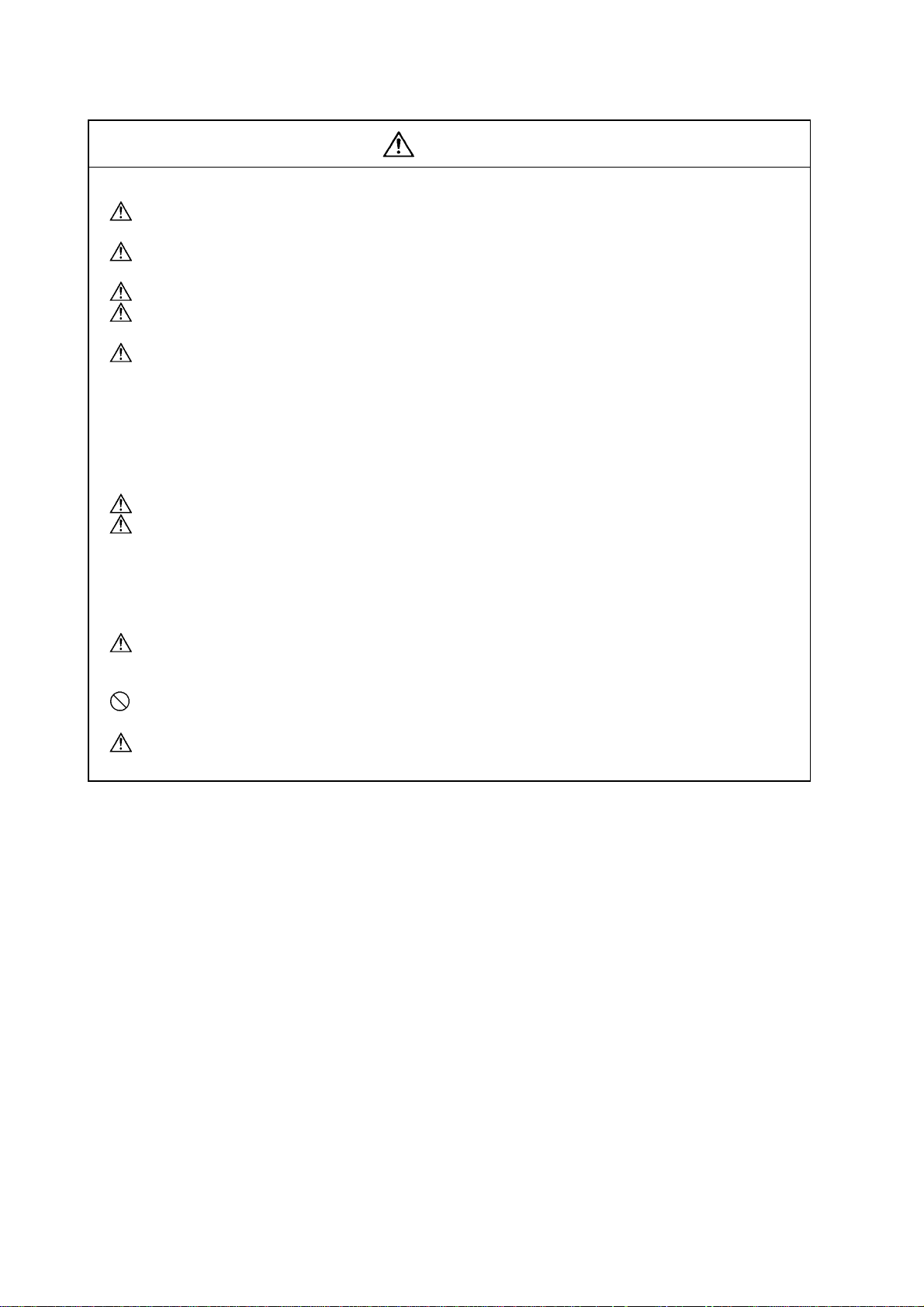
In the case of a lathe, the axis parallel to the spindle is known as the Z axis and its forward direct ion
is the direction in which the turret moves away from the spindle stock while the axis at right angles
to the Z axis is the X axis and its forward direction is the direction in which it moves away from the Z
axis, as shown in the figure below.
1.1 Coordinate Words and Control Axes
indle stock
S
+Y
Tailstock
Tool
Tu
et
+Z
+X
Coordinate axes and polarities
Since coordinates based on the right hand rule are used with a lathe, the forward directio n of the Y
axis in the above figure which is at right angles to the X-Z plane is downward. It should be borne in
mind that an arc on the X-Z plane is expressed as clockwise or counterclockwi se as seen from the
forward direction of the Y axis. (Refer to the section on circular interpolation.)
Spindle nose
Machine zero point
G54
G55
G58
G52
Workpiece zero points (G54 to G59)
G59
Local coordinate system
(Valid in G54 to G59)
G30
2nd reference position
+Z
G28
+X
Reference position
(+Y)
Relationship between coordinates
1
Page 14
1. Control Axes
1.2 Coordinate Systems and Coordinate Zero Point Symbols
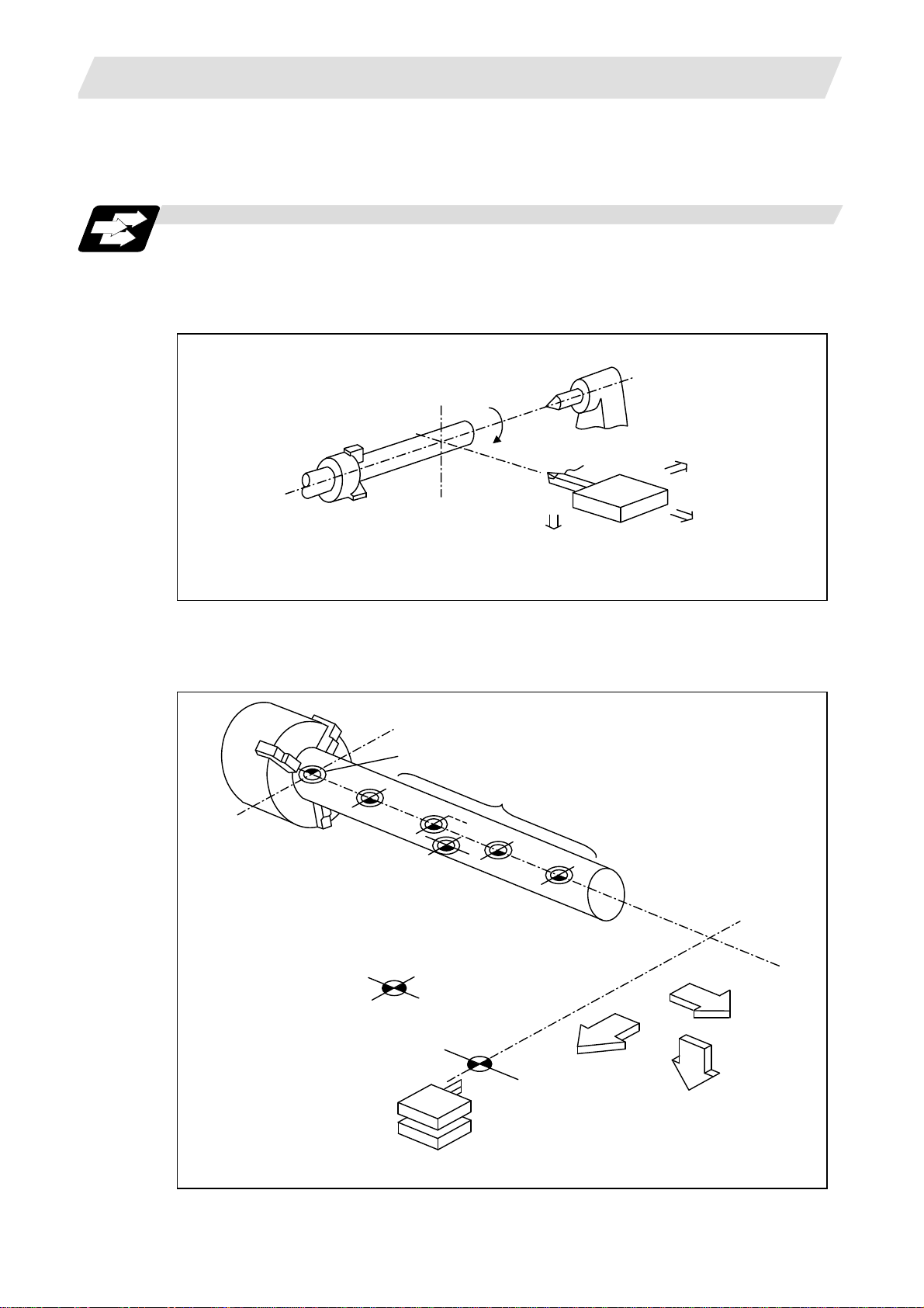
1.2 Coordinate Systems and Coordinate Zero Point Symbols
Function and purpose
: Reference position
: Machine coordinate origin
: Workpiece coordinate zero points
(G54 to G59)
Upon completion of the reference position return, the parameters are referred to and automatically
set for the basic machine coordinate system and workpiece coordinate systems (G54 to G59).
The basic machine coordinate system is set so that the first reference position is at the position
designated by the parameter from the basic machine coordinate zero point (machine zero point).
Basic machine
coordinate system
Hypothetical machine
coordinate system
(shifted by G92)
Machine zero point
Z2
X
2
+X
Workpiece
coordinate
system
1 (G54)
Workpiece
coordinate
system
2 (G55)
+Z
Workpiece
coordinate
system
5 (G58)
Workpiece
coordinate
system6
(G59) Z
3
X
Z
3
Local
coordinate
system
X1
(G52)
1
1st reference position
The local coordinate system (G52) is valid on the co ordinate systems designated by the commands
for the workpiece coordinate systems 1 to 6.
Using the G92 command, the basic machine coordinate system can be shifted and made the
hypothetical machine coordinate system. At the same time, workpiece coordinate systems 1 to 6
are also shifted.
2
Page 15
2. Least Command Increments
2. Least Command Increments
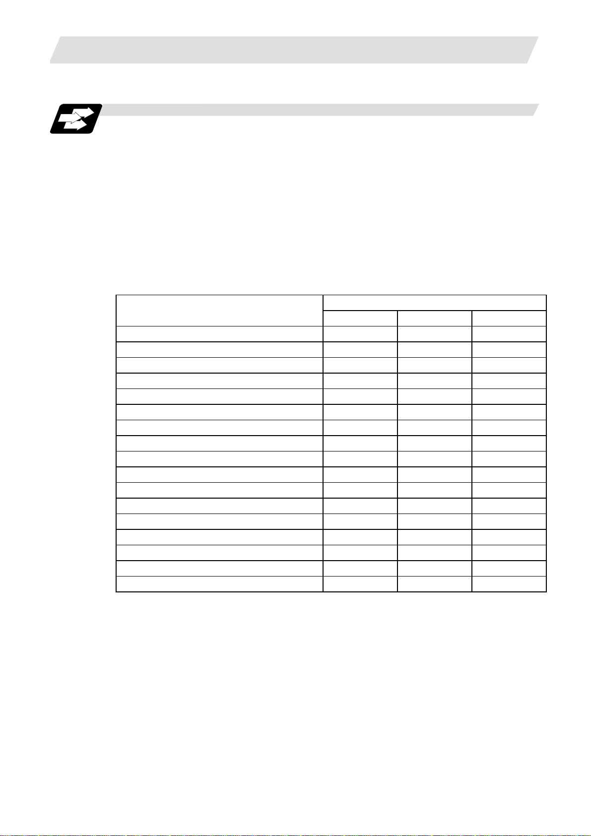
2.1 Input Setting Units
Function and purpose
The input setting units are, as with the compensation amounts, the units of setting data used in
common for all axes.
The command units are the movement amounts in the program which are commanded with MDI
inputs or command tape. These are expressed with mm, inch or degree (°) units.
With the parameters, the command units are decided for each axis, and the input setting units are
decided commonly for all axes.
#1003 iunit = B
Input setting unit
Command unit
(Note 1) Inch/metric changeover is performed in either of 2 ways: conversion from the parameter
screen (#1041 I_inch: valid only when the power is turned ON) and conversion using the
G command (G20 or G21).
However, when a G command is used for the conversion, the conversion applies only to
the input command increments and not to the input setting units.
Consequently, the tool offset amounts and other compensation amounts as well as the
variable data should be preset to correspond to inches or millimeters.
= C
= D
= E
#1015 cunit = 0 Follow #1003 iunit
= 1
= 10
= 100
= 1000
= 10000
Parameters
2.1 Input Setting Units
Linear axis
Millimeter Inch
0.001 0.0001 0.001
0.0001 0.00001 0.0001
0.00001 0.000001 0.00001
0.000001 0.0000001 0.000001
0.0001 0.00001 0.0001
0.001 0.0001 0.001
0.01 0.001 0.01
0.1 0.01 0.1
1.0 0.1 1.0
Rotation axis
(°)
(Note 2) The millimeter and inch systems cannot be used together.
(Note 3) During circular interpolation on an axis where the input command increments are different,
the center command (I, J, K) and the radius command (R) can be designated by the input
setting units. (Use a decimal point to avoid confusion.)
3
Page 16
2. Least Command Increments
2.1 Input Setting Units
Data
Speed data
Example:
rapid
Position data
Example:
SoftLimit+
Interpolation
unit data
Detailed description
(1) Units of various data
These input setting units determine the parameter setting unit, program comman d unit and the
external interface unit for the PLC axis and handle pulse, etc. The followin g rules show how the
unit of each data changes when the input setting unit is changed. This table applies to the NC
axis and PLC axis.
Unit
system
metre
Inch
metre
Inch
metre
Inch
(2) Program command
The program command unit follows the above table.
If the data has a decimal point, the number of digits in the integer section will remain and the
number of digits in the decimal point section will increase as the input setting unit becomes
smaller.
When setting data with no decimal point, and which is a position command, the data will be
affected by the input setting increment and input command increment.
For the feed rate, as the input setting unit becomes smaller, the number of digits in the integer
section will remain the same, but the number of digits in the decimal point section will increase.
Setting value
20000 (mm/min) 20000 20000 20000 20000Milli-
Setting range 1 to 999999 1 to 999999 1 to 999999 1 to 999999
2000 (inch/min) 20000 20000 20000 20000
Setting range 1 to 999999 1 to 999999 1 to 999999 1 to 999999
123.123 (mm) 123.123 123.1230 123.12300 123.123000MilliSetting range ±99999.999 ±99999.9999 ±99999.99999 ±99999.999999
12.1234 (inch) 12.1234 12.12340 12.123400 12.1234000
Setting range ±9999.9999 ±9999.99999 ±9999.999999 ±9999.9999999
1 (µm) 2 20 200 2000Milli-
Setting range ±9999 ±9999 ±9999 ±9999
0.0001 (inch) 2 20 200 2000
Setting range ±9999 ±9999 ±9999 ±9999
Input setting unit
1µm (B) 0.1µm (C) 10nm (D) 1nm (E)
4
Page 17

2. Least Command Increments
2.2 Indexing Increment
Function and purpose
This function limits the command value for the rotary axis.
This can be used for indexing the rotary table, etc. It is possible to cause a program error with a
program command other than an indexing increment (parameter setting value).
Detailed description
When the indexing increment (parameter) for limiting the command value is set, the rotary axis can
be positioned with that indexing increment. If a program other than the indexing increment setting
value is commanded, a program error (P20) will occur.
The indexing position will not be checked when the parameter is set to 0.
(Example) When the indexing increment setting value is 2 degrees, only command with the
2-degree increment are possible.
G90 G01 C102. 000 ; … Moves to the 102 degree angle.
G90 G01 C101. 000 : … Program error
G90 G01 C102 ; … Moves to the 102 degree angle. (Decimal point type II)
The following axis specification parameters are used.
# Item Contents
2106 Index unit Indexing
Precautions
• When the indexing increment is set, degree increment positioning takes place.
• The indexing position is checked with the rotary axis, and is not checked with other axes.
• When the indexing increment is set to 2 degrees, the rotary axis is set to the B axis, and the B axis
is moved with JOG to the 1.234 position, an indexing error will occur if "G90B5." or "G91B5." is
commanded.
increment
2.2 Indexing Increment
Set the indexing increment to which the rotary
axis can be positioned.
Setting range
(unit)
0 to 360 (° )
5
Page 18
3. Data Formats
3. Data Formats
3.1 Tape Codes
Function and purpose
The tape command codes used for this controller are combinations of alphabet letters (A, B, C, ...
Z), numbers (0, 1, 2, ... 9) and signs (+, -, /, ...). These alphabet letters, numbers and signs are
referred to as characters. Each character is represented by a combination of 8 holes which may, or
may not, be present.
These combinations make up what is called codes.
This controller uses the ISO code (R-840).
(Note 1) If a code not given in the "Table of tape codes" is assigned during operation, a program
(Note 2) For the sake of convenience, a " ; " has been used in the CNC display to indi cate the End
CAUTION
" ; " "EOB" and " % " "EOR" are explanatory notations. The actual code is "Line feed" and "%".
(ISO code (R-840)
3.1 Tape Codes
error (P32) will result.
of Block (EOB/LF) which separates one block from another. Do not use the " ; " key,
however, in actual programming but use the keys in the following table instead.
Detailed description
(1) Use the keys in the following table for programming.
EOB/EOR keys and displays
Key used
End of Block LF or NL ;
End of Record % %
(2) Significant data section (label skip function)
All data up to the first EOB ( ; ), after the power has been turned ON or after operation has been
reset, are ignored during automatic operation based on tape, memory loading operation or
during a search operation. In other words, the significant data section of a tape extends from
the character or number code after the initial EOB ( ; ) code after resetting to the point where
the reset command is issued.
Code used
ISO Screen display
6
Page 19
3. Data Formats
G
R
•
•••••••
•••
•
•
•
•••••••••
•••••••
•
•
•••••••••••••••••••
•
•
•••••••••••••••
•
•••••••••
(3) Control out, control in
When the ISO code is used, all data between control out "(" and control in ")" (or ";") are
ignored, although these data appear on the setting and display unit. Consequently, the
command tape name, No. and other such data not directly related to control can be inserted in
this section.
This information (except (B) in the "Table of tape codes") will also be loaded, ho wever, during
tape loading. The system is set to the "control in" mode when the power is turned ON.
Example of ISO code
3.1 Tape Codes
•
••
• • • • • • • • • • • • • • • • • • • • • • • • • • • • • • • • • • • • • • • • • • • • • • • •
•
• •••
••
• •••
••
•
• • •• •
Operator information print-out example
L C S L
00X-85000Y-64000 (CUTTE
F R
• ••
•• •• •
••
••
•
Information in this section is ignored and nothing is executed.
RE T URN)
P
• • •
•• •
••• • ••
•••
•
•••••
•• • • •
F
••
•••••
•
•
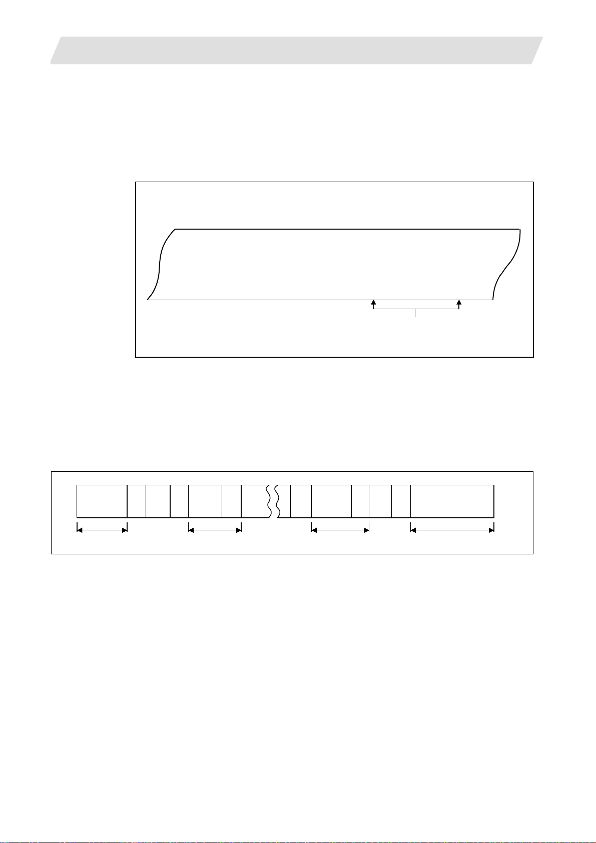
(4) EOR (%) code
Generally, the End of Record code is punched at both ends of the tape. It has the following
functions:
(a) Rewind stop when rewinding tape (with tape rewinder)
(b) Rewind start during tape search (with tape rewinder)
(c) Completion of loading during tape loading into memory
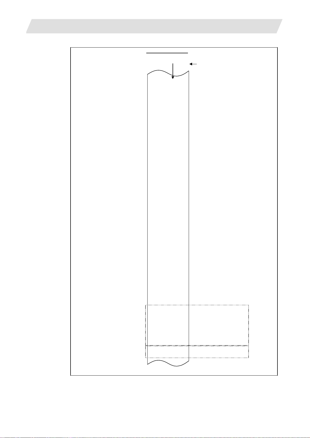
(5) Tape preparation for tape operation (with tape rewinder)
……… ……… …………..
Initial block
Last block
10cm
%;;;;
2m
2m
10cm
%
If a tape rewinder is not used, there is no need for the 2-mete r dummy at both ends of the tape
and for the head EOR (%) code.
7
Page 20
3. Data Formats
•
X
Y
/
(
(
)
)
(
)
[
]
)
)
@
)
)
3.1 Tape Codes
ISO code (R-840)
Feed holes
8 7 6 5 4 3 2 1 Channel No.
•
•
•
•
•
•
•
•
•
•
•
•
•
•
•
•
•
•
•
•
•
•
•
•
•
•
•
•
•
•
•
•
•
•
•
•
•
•
•
•
•
•
•
•
•
•
•
•
•
•
•
•
•
•
•
•
•
•
•
•
•
•
•
•
•
•
•
•
•
Under the ISO code, LF or NL is EOB and % is EOR.
1
2
3
4
5
6
7
8
9
0
A
B
C
D
E
F
G
H
I
J
K
L
M
N
O
P
Q
R
S
T
U
V
W
Z
+
.
,
%
LF(Line Feed) or NL
Control Out
Control In
:
#
*
=
!
$
SP(Space
CR(Carriage Return)
BS(Back Space)
HT(Horizontal Tab)
&
’(Apostrophe
;
<
>
?
”
DEL (Delete
NULL
DEL (Delete
(A)
(B)
The (A) codes are stored on tape but an error results (except when they are used in the
comment section) during operation.
The (B) codes are non-working codes and are always ignored. (Parity V check is not
executed.)
Table of tape codes
8
Page 21
3. Data Formats
A
3.2 Program Formats
Function and purpose
The prescribed arrangement used when assigning control informati on to the controller is know n as
the program format, and the format used with this controller is called the "word address format".
Detailed description
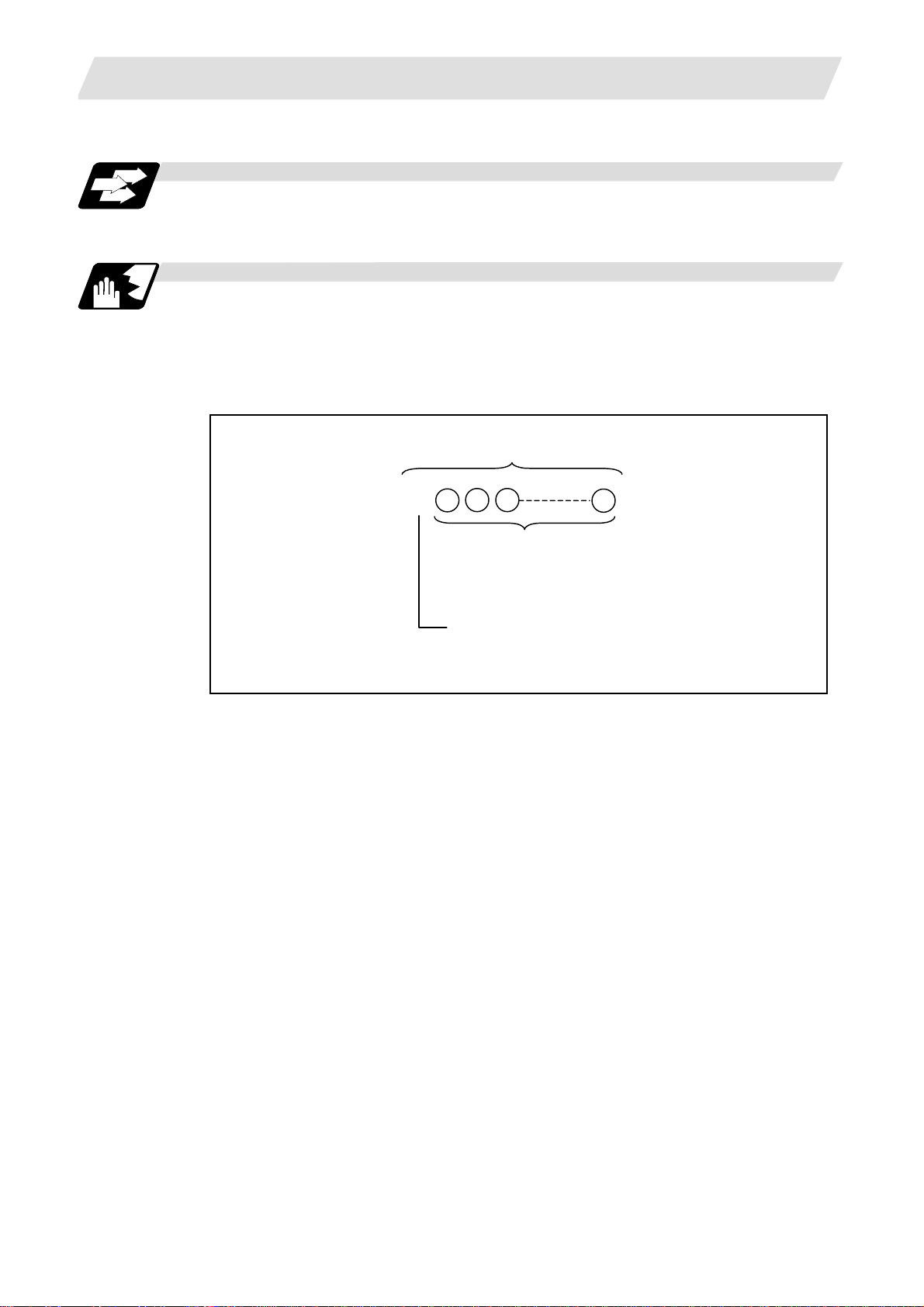
(1) Word and address
A word is a collection of characters arranged in a specific sequence. This entity is used as the
unit for processing data and for causing the machine to execute specific operations. Each word
used for this controller consists of an alphabet letter and a number of several digits. (A + or sign may be attached to the head of a number.)
3.2 Program Formats
Word
*
Numerals
lphabet (address)
Word configuration
The alphabet letter at the head of the word is the address. It defines the meaning of the
numerical information which follows it.
For details of the types of words and the number of significant digits of words used for this
controller, refer to "Format details".
(2) Blocks
A block is a collection of words. It includes the information which is required for the machin e to
execute specific operations. One block unit constitutes a complete command. The end of each
block is marked with an EOB (End of Block) code.
(3) Programs
A program is a collection of several blocks.
9
Page 22

3. Data Formats
<Format detail abbreviations>
Program No. 08
Sequence No. N6
Preparatory function G3/G21
0.001(°) mm/
0.0001 inch
0.0001(°) mm/
Movement
axis
Arc and
cutter
radius
Dwell 0.001(sec.) X+53/P+8
Feed
function
Tool offset
Miscellaneous function (M)
Spindle function (S)
Tool function (T)
2nd miscellaneous function A8/B8/C8
Subprogram
Fixed
cycle
0.00001 inch
0.00001(°) mm/
0.000001 inch
0.000001(°) mm/
0.0000001 inch
0.001(°) mm/
0.0001 inch
0.0001(°) mm/
0.00001 inch
0.00001(°) mm/
0.000001 inch
0.000001(°) mm/
0.0000001 inch
0.001(°) mm/
0.0001 inch
0.0001(°) mm/
0.00001 inch
0.00001(°) mm/
0.000001 inch
0.000001(°) mm/
0.0000001 inch
0.001(°) mm/
0.0001 inch
0.0001(°) mm/
0.00001 inch
0.00001(°) mm/
0.000001 inch
0.000001(°) mm/
0.0000001 inch
Metric command Inch command
X+53 Z+53 α+53 X+44 Z+44 α+44 X+53 Z+53 α+53 X+53 Z+53 α+53
X+54 Z+54 α+54 X+45 Z+45 α+45 X+54 Z+54 α+54 X+54 Z+54 α+54
X+55 Z+55 α+55 X+46 Z+46 α+46 X+55 Z+55 α+55 X+55 Z+55 α+55
X+56 Z+56 α+56 X+47 Z+47 α+47 X+56 Z+56 α+56 X+56 Z+56 α+56
I+53 K+53 R+53 I+44 K+44 R+44 I+53 K+53 R+53
I+54 K+54 R+54 I+45 K+45 R+45 I+54 K+54 R+54
I+55 K+55 R+55 I+46 K+46 R+46 I+55 K+55 R+55
I+56 K+56 R+56 I+47 K+47 R+47 I+56 K+56 R+56
F62(Feed per minute)
F44(Feed per revolution)
F63(Feed per minute)
F45(Feed per revolution)
F64(Feed per minute)
F46(Feed per revolution)
F65(Feed per minute)
F47(Feed per revolution)
T1/T2
M8
S8
T8
P8 H5 L4
R+53 Q53 P8 L4
R+54 Q54 P8 L4
R+55 Q55 P8 L4
R+56 Q56 P8 L4
← ← ←
← ← ←
← ← ←
← ← ←
F53(Feed per minute)
F26(Feed per revolution)
F54(Feed per minute)
F27(Feed per revolution)
F55(Feed per minute)
F28(Feed per revolution)
F56(Feed per minute)
F29(Feed per revolution)
← ← ←
← ← ←
← ← ←
← ← ←
← ← ←
← ← ←
← ← ←
← ← ←
← ← ←
← ← ←
3.2 Program Formats
Rotary axis
(Metric command)
F63(Feed per minute)
F43(Feed per revolution)
F64(Feed per minute)
F44(Feed per revolution)
F65(Feed per minute)
F45(Feed per revolution)
F66(Feed per minute)
F46(Feed per revolution)
Rotary axis
(Inch command)
I+44 K+44 R+44
(Note 5)
I+45 K+45 R+45
(Note 5)
I+46 K+46 R+46
(Note 5)
I+47 K+47 R+47
(Note 5)
F44(Feed per minute)
F34(Feed per revolution)
(Note 6)
F55(Feed per minute)
F35(Feed per revolution)
(Note 6)
F56(Feed per minute)
F36(Feed per revolution)
(Note 6)
F57(Feed per minute)
F37(Feed per revolution)
(Note 6)
(Note 1) α indicates the additional axis address, such as A, B or C.
(Note 2) The number of digits check for a word is carried out with the maximum number of digits of that
address.
(Note 3) Numerals can be used without the leading zeros.
10
Page 23

3. Data Formats
3.2 Program Formats
(Note 4) The meanings of the details are as follows :
Example 1 : 08 : 8-digit program No.
Example 2 : G21 : Dimension G is 2 digits to the left of the decimal point, and 1 digit to the right.
Example 3 : X+53 : Dimension X uses + or - sign and represents 5 digits to the left of the
decimal point and 3 digits to the right.
For example, the case for when the X axis is positioned (G00) to the 45.123 mm position in the
absolute value (G90) mode is as follows :
X45.123 ;
G00
3 digits below the decimal point
5 digits above the decimal point, so it's +00045, but the leading zeros and the
mark (+) have been omitted.
G0 is possible, too.
(Note 5) If an arc is commanded using a rotary axis and linear axis while inch commands are being used,
the degrees will be converted into 0.1 inches for interpolation.
(Note 6) While inch commands are being used, the rotary axis speed will be in increm ents of 10 degrees.
Example : With the F1. (Feed per minute) command, this will become the 10 degrees/minute
command.
(Note 7) The decimal places below the decimal point are ignored when a command, such as an S
command, with an invalid decimal point has been assigned with a decimal poi nt.
(Note 8) This format is the same for the value input from the memory, MDI or setting and display unit.
(Note 9) Command the program No. in an independent block. Command the program NO. in the head
block of the program.
11
Page 24

3. Data Formats
3.3 Tape Memory Format
Function and purpose
(1) Storage tape and significant sections (ISO, EIA automatic judgment)
Both ISO and EIA tape codes can be stored in the memory in the same way as tape ope ration.
After resetting, ISO/EIA is automatically judged by the EOB code at the head.
The interval to be stored in the memory is from the next character after the head EOB to the
EOR code after resetting.
The significant codes listed in the "Table of tape code" in Section 3.1 "Tape codes", in the
above significant section are actually stored into the memory. All other codes are ignored and
are not stored.
The data between control out "(" and control in ")" are stored into the memory.
3.4 Optional Block Skip
3.4.1 Optional Block Skip; /
3.3 Tape Memory Format
Function and purpose
This function selectively ignores specific blocks in a machining program which starts with the "/"
(slash) code.
Detailed description
(1) Provided that the optional block skip switch is ON, blocks starting with the "/" code are ignored.
They are executed if the switch is OFF.
Parity check is valid regardless of whether the optional block skip switch is ON or OFF.
When, for instance, all blocks are to be executed for one workpiece but specific block are not to
be executed for another workpiece, the same comman d tape can be used to machine diffe rent
parts by inserting the "/" code at the head of those specific blocks.
Precautions for using optional block skip
(1) Put the "/" code for optional block skip at the beginning of a block. If it is placed inside the block,
it is assumed as a user macro, a division instruction.
(Example) N20 G1 X25. /Z25. ; ..........NG (User macro, a division instruction;
/N20 G1 X25. Z25. ; ..........OK
(2) Parity checks (H and V) are conducted regardless of the optional block skip switch position.
(3) The optional block skip is processed immediately before the pre-read buffer.
Consequently, it is not possible to skip up to the block which has been read into the pre-read
buffer.
(4) This function is valid even during a sequence No. search.
(5) All blocks with the "/" code are also input and output during tape storing and tape output,
regardless of the position of the optional block skip switch.
a program error results.)
12
Page 25
3. Data Formats
3.4.2 Optional Block Skip Addition ; /n
3.4 Optional Block Skip
Function and purpose
Whether the block with "/n (n:1 to 9)" (slash) is executed du ring automatic operation an d searching
is selected.
By using the machining program with "/n" code, different parts can be machined by the same
program.
Detailed description
The block with "/n" (slash) code is skipped when the "/n" is programmed to the head of the block
and the optional block skip signal is turned ON.
For the block with the "/n" code inside the block (not the head of block), the program is operated
according to the value of the parameter "#1226 aux10/bit1" setting.
When the optional block skip signal is OFF, the block with "/n" is executed.
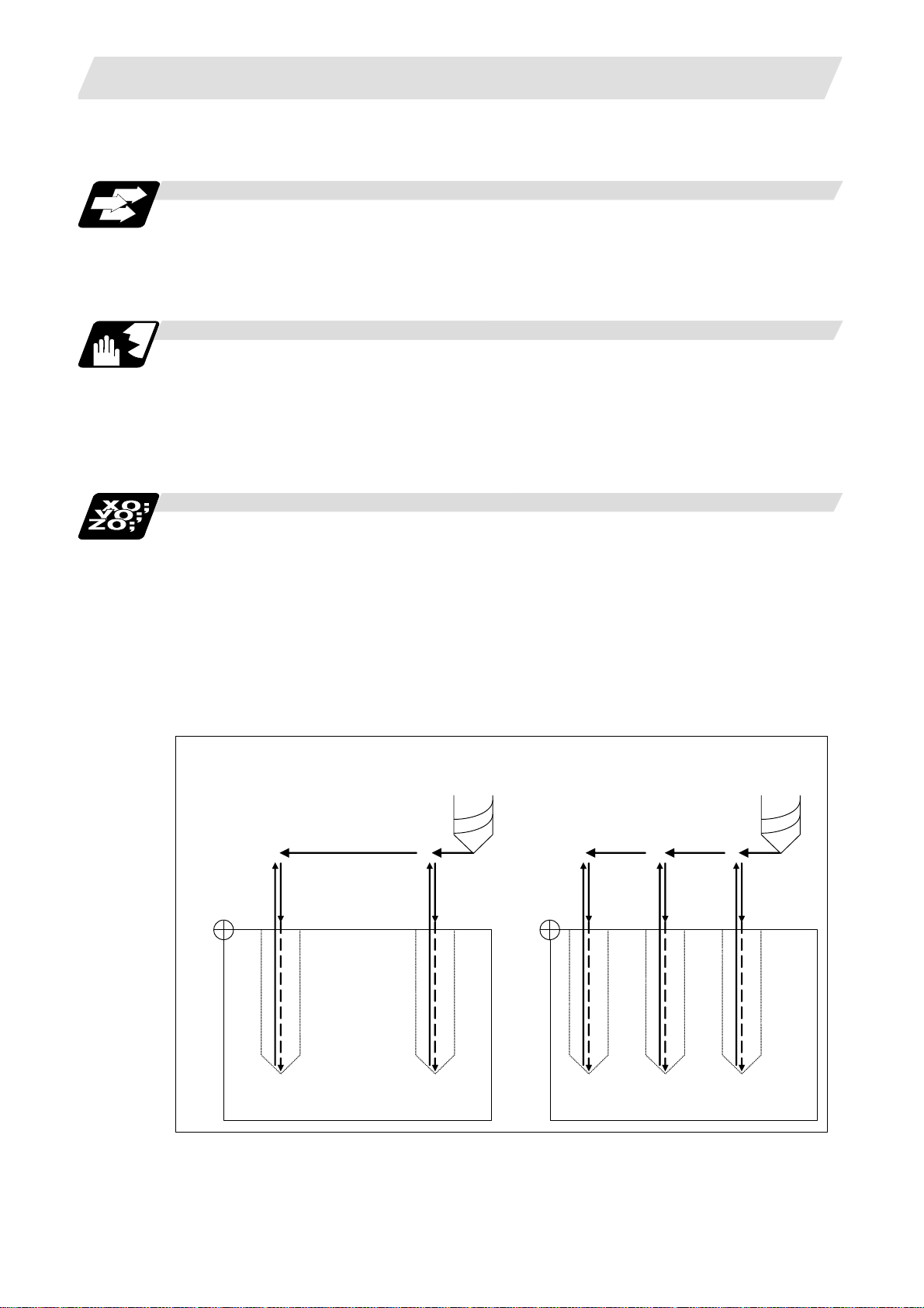
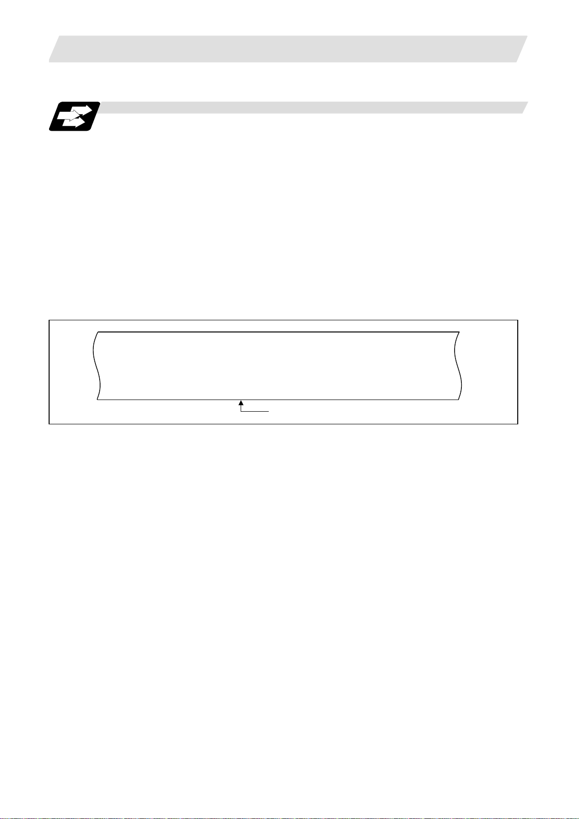
Example of program
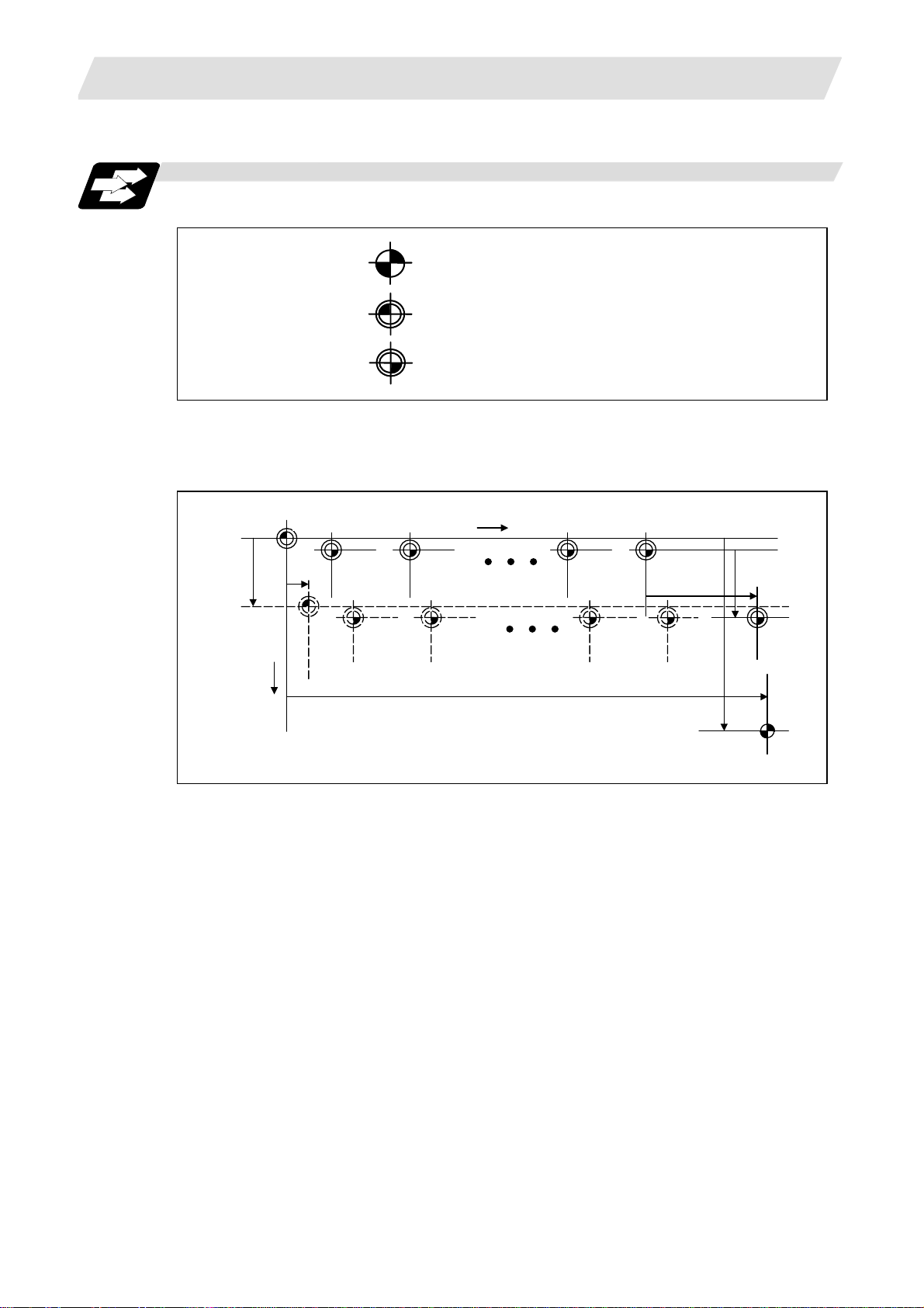
(1) When the 2 parts like the figure below are machined, the following program is used. When the
optional block skip 5 signal is ON, the part 1 is created. When the optional blo ck skip 5 signal is
OFF, the part 2 is created.
<Program>
N1 G54;
N2 G90G81X50. Z-20. R3. F100;
/5 N3 X30.;
N4 X10.;
N5 G80;
M02;
Part 1
the optional block skip 5 signal ON
Part 2
the optional block skip 5 signal OFF
N4 N2 N2 N3
13
N4
Page 26

3. Data Formats
3.4 Optional Block Skip
(2) When two or more "/n" codes are commanded to the head of the same block, the block is
ignored if either of the optional block skip signal corresponding to the command i s ON.
<Program>
N01 G90 Z3. M03 S1000;
/1/2 N02 G00 X50.;
/1/2 N03 G01 Z-20. F100;
/1/2 N04 G00 Z3.;
/1 /3 N05 G00 X30.;
/1 /3 N06 G01 Z-20. F100;
/1 /3 N07 G00 Z3.;
/2/3 N08 G00 X10.;
/2/3 N09 G01 Z-20. F100;
/2/3 N10 G00 Z3.;
N11 G28 X0 M05;
(a) Optional block skip 1 signal ON
(Optional block skip 2, 3 signals OFF)
N01 -> N08 -> N09 -> N10 -> N11 -> N12
(b) Optional block skip 2 signal ON
(Optional block skip 1, 3 signals OFF)
N01 -> N05 -> N06 -> N07 -> N11 -> N12
(c) Optional block skip 3 signal ON
(Optional block skip 1, 2 signals OFF)
N01 -> N02 -> N03 -> N04 -> N11 -> N12
N12 M02;
(3) When the parameter "#1226 aux10/bit1" is "1", when two or more "/n" are commanded inside
the same block, the commands following "/n" in the block are ignored if either of the optional
block skip signal corresponding to the command is ON.
N01 G91 G28 X0.Y0.Z0.;
N02 G01 F1000;
N03 X1. /1 Y1. /2 Z1.;
N04 M30;
(a) When the optional block skip 1 signal is ON
and the optional block skip 2 signal is OFF,
"Y1. Z1." is ignored
(b) When the optional block skip 1 signal is
OFF and the optional block skip 2 signal is
ON, "Z1." is ignored.
14
Page 27
3. Data Formats
3.5 Program/Sequence/Block Nos.; O, N
Function and purpose
These Nos. are used for monitoring the execution of the machining programs and for calling both
machining programs and specific stages in machining programs.
(1) Program Nos. are classified by workpiece correspondence or by subprogram units, and they
are designated by the address "O" followed by a number with up to 8 digits.
(2) Sequence Nos. are attached where appropriate to command blocks which configure ma chining
programs, and they are designated by the address "N" followed by a number with up to 6 digits.
(3) Block Nos. are automatically provided internally. They are preset to zero every time a program
No. or sequence No. is read, and they are counted up one at a time unless program Nos. or
sequence Nos. are commanded in blocks which are subsequently read.
Consequently, all the blocks of the machining programs given in the table below can be
determined without further consideration by combinations of program Nos., sequence Nos. an d
block Nos.
3.5 Program/Sequence/Block Nos.; O, N
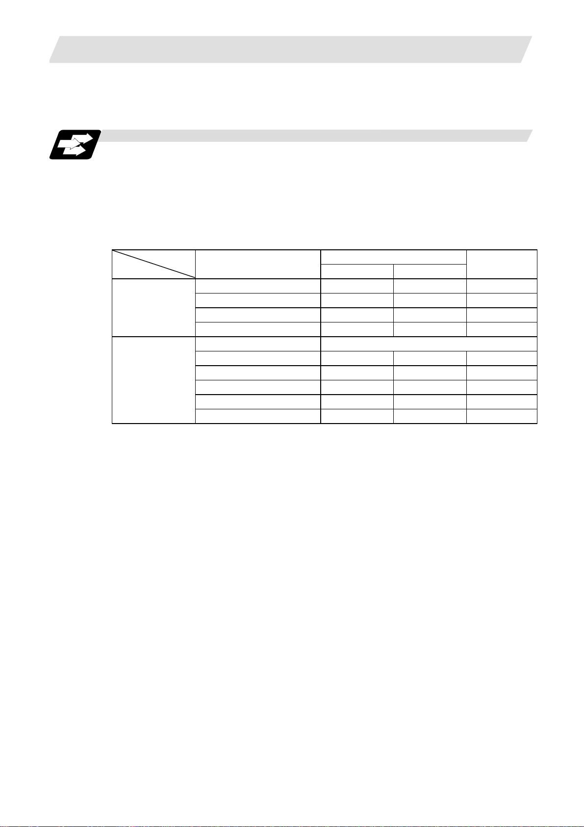
Machining program
Program No. Sequence No. Block No.
O12345678 (DEMO, PROG) ; 12345678 0 0
N100 G00 G90 X120. Z100. ; 12345678 100 0
G94 S1000 ; 12345678 100 1
N102 G71 P210 Q220 I0.2 K0.2 D0.5 F600 ; 12345678 102 0
N200 G94 S1200 F300 ; 12345678 200 0
N210 G01 X0 Z95. ; 12345678 210 0
G01 X20. ; 12345678 210 1
G03 X50. Z80. K–15. ; 12345678 210 2
G01 Z55. ; 12345678 210 3
G02 X80. Z40. I15. ; 12345678 210 4
G01 X100. ; 12345678 210 5
G01 Z30. ; 12345678 210 6
G02 Z10. K–15. ; 12345678 210 7
N220 G01 Z0 ; 12345678 220 0
N230 G00 X120. Z150. ; 12345678 230 0
N240 M02 ; 12345678 240 0
% 12345678 240 0
Monitor display
15
Page 28
3. Data Formats
• • •• •
•
• •• •• ••• • • •• •
• • • • • • •
•• • •• • • •
•••••••
•
•
•••••••••••••••
•
•••••••••••••
•
•••••
•••••
•
3.6 Parity H/V
Function and purpose
Parity check provides a mean of checking whether the tape has been correctly perforated or not.
This involves checking for perforated code errors or, in other words, for perforation errors. There
are two types of parity check: Parity H and Parity V.
(1) Parity H
3.6 Parity H/V
Parity H checks the number of holes configuring a character and it is done during tape
operation, tape input and sequence No. search.
A parity H error is caused in the following cases.
(a) ISO code
When a code with an odd number of holes in a significant data secti on has been detected.
(b) EIA code
When a code with an even number of holes in a significant data section has been
detected.
(Example 1) Parity H error example (For ISO codes)
• • •• • •
• • •• • • •••
• • • • • • • • • • • • • • • • • • • • • • • • • • • • • • • • • • • • • • • • • • • • • • • • •
• •• •
••
•• •
• • • •
• •
(2) Parity V
••••
••
When a parity H error occurs, the tape stops following the alarm code.
A parity V check is done during tape operation, tape input and sequence No. search when the
I/O PARA #9n15 (n is the unit No.1 to 5) parity V check function is set to "1". It is not done
during memory mode.
A parity V error occurs in the following case: when the number of codes from the first significant
code to the EOB (;) in the significant data section in the vertical direction of the tape is an odd
number, that is, when the number of characters in one block is odd.
When a parity V error is detected, the tape stops at the code following the EOB (;).
(Note 1) Among the tape codes, there are codes which are counted as characters for parity
and codes which are not counted as such. For details, refer to the "Table of tape
code" in Section 3.1 "Tape codes".
(Note 2) Any space codes which may appear within the section from the initial EOB code to the
address code or "/" code are counted for parity V check.
•••
•••
•• ••••
••
••••
This character causes a parity H error.
• •
• •
••••
•••
•••
•
16
Page 29
3. Data Formats
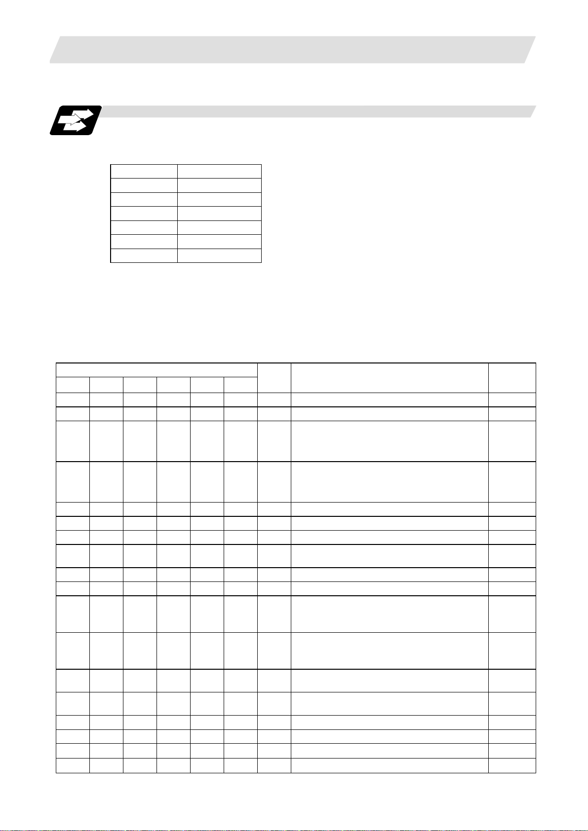
3.7 G Code Lists
Function and purpose
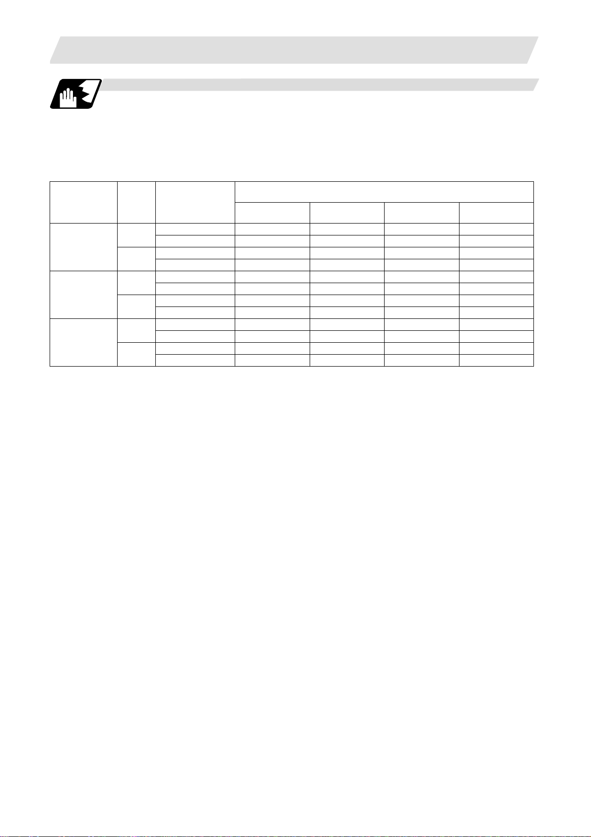
G codes include the six G code lists 2, 3, 4, 5, 6 and 7. One list is selected by setting in parameter
"#1037 cmdtyp".
cmdtyp G code list
3 List 2
4 List 3
5 List 4
6 List 5
7 List 6
8 List 7
G functions are explained using the G code list 3.
(Note 1) A program error (P34) will result if a G code that is not in the Table of G code lists is
(Note 2) An alarm will result if a G code without additional specifications is comman ded.
commanded.
3.7 G Code Lists
Table of G code lists
G code list
2 3 4 5 6 7
ΔG00 ΔG00 ΔG00 ΔG00 ΔG00 ΔG00
ΔG01 ΔG01 ΔG01 ΔG01 ΔG01 ΔG01
G02 G02 G02 G02 G02 G02 01
G03 G03 G03 G03 G03 G03 01
G02.3 G02.3 G02.3 G02.3 G02.3 G02.3 01
G03.3 G03.3 G03.3 G03.3 G03.3 G03.3 01
G04 G04 G04 G04 G04 G04 00
G09 G09 G09 G09 G09 G09 00
G10 G10 G10 G10 G10 G10 00
G11 G11 G11 G11 G11 G11 00
G12.1 G12.1 G12.1 G12.1 19
*G13.1 *G13.1 *G13.1 *G13.1 19
*G14 *G14 *G14 *G14 18
G15 G15 G15 G15 18
G07.1
G107
G12.1
G112
G13.1
G113
G07.1
G12.1
G13.1
Group Function Section
01
01
G107
G112
G113
19
19
19
Positioning 6.1
Linear interpolation 6.2
Circular interpolation CW /
Helical interpolation CW
Circular interpolation CCW /
Helical interpolation CCW
6.3
6.4
6.7
6.3
6.4
6.7
Exponential interpolation CW 6.11
Exponential interpolation CCW 6.11
Dwell 8.1
Cylindrical interpolation 6.9
Exact stop check 7.10
Parameter/Compensation data input by
program/
Tool life management data registration
Program parameter input / Tool life
management data registration mode
cancel
12.5
13.15
12.5
13.15
Polar coordinate interpolation ON 6.10
Polar coordinate interpolation cancel 6.10
Milling interpolation ON 6.8
Milling interpolation cancel 6.8
• Balance cut OFF
• Balance cut ON
13.18
13.18
17
Page 30

3. Data Formats
3.7 G Code Lists
G code list
2 3 4 5 6 7
G16 G16 G16 G16 02
ΔG17 ΔG17 ΔG17 ΔG17 ΔG17 ΔG17
ΔG18 ΔG18 ΔG18 ΔG18 ΔG18 ΔG18
ΔG19 ΔG19 ΔG19 ΔG19 ΔG19 ΔG19
ΔG20 ΔG20 ΔG20 ΔG20 ΔG20 ΔG20
ΔG21 ΔG21 ΔG21 ΔG21 ΔG21 ΔG21
G22 G22 G22 G22 04
*G23 *G23 *G23 *G23 04
G22 G22 00
G23 G23 00
G27 G27 G27 G27 G27 G27 00
G28 G28 G28 G28 G28 G28 00
G29 G29 G29 G29 G29 G29 00
G30 G30 G30 G30 G30 G30 00
G30.1 G30.1 G30.1 G30.1 G30.1 G30.1
G30.2 G30.2 G30.2 G30.2 00
G30.3 G30.3 G30.3 G30.3 00
G30.4 G30.4 G30.4 G30.4 00
G30.5 G30.5 G30.5 G30.5 00
G31 G31 G31 G31 G31 G31 00
G31.1 G31.1 G31.1 G31.1 G31.1 G31.1
G31.2 G31.2 G31.2 G31.2 G31.2 G31.2
G31.3 G31.3 G31.3 G31.3 G31.3 G31.3
G32 G33 G32 G33 G32 G33 01
G34 G34 G34 G34 G34 G34 01
G35 G35 G35 G35 G35 G35 01
G36 G36 G36 G36 G36 G36 01
G36/G37
G37 G37 G36/G37 G36/G37
*G40 *G40 *G40 *G40 *G40 *G40 07
G41 G41 G41 G41 G41 G41 07
G42 G42 G42 G42 G42 G42 07
G46 G46 G46 G46 G46 G46 07
G37.1
G37.2
G36/G37
Group Function Section
02
02
02
06
06
00
00
00
00
G37.1
G37.2
00
Milling interpolation plane selection Y-Z
cylindrical plane
6.8.3
Plane selection X-Y 6.5
Plane selection Z-X 6.5
Plane selection Y-Z 6.5
Inch command 5.3
Metric command 5.3
Barrier check ON 15.1
Barrier check OFF 15.1
Soft limit ON 15.2
Soft limit OFF 15.2
Reference position return check 14.9
Automatic reference position return 14.7
Return from reference position 14.7
2nd, 3rd and 4th reference position return 14.8
Tool change position return 1 13.17
Tool change position return 2 13.17
Tool change position return 3 13.17
Tool change position return 4 13.17
Tool change position return 5 13.17
Skip function/Multiple-step skip function 2 16.2
16.4
Multiple-step skip function 1-1 16.3
Multiple-step skip function 1-2 16.3
Multiple-step skip function 1-3 16.3
Thread cutting 6.6.1
6.6.2
Variable lead thread cutting 6.6.4
Circular thread cutting CW 6.6.5
Circular thread cutting CCW 6.6.5
Automatic tool length measurement 16.1
Tool nose R compensation cancel 12.4
Tool nose R compensation left 12.4
Tool nose R compensation right 12.4
Tool nose R compensation (direction
automatically selected) ON
12.4
18
Page 31

3. Data Formats
3.7 G Code Lists
G code list
2 3 4 5 6 7
G43.1 G43.1 G43.1 G43.1 G43.1 G43.1
G44.1 G44.1 G44.1 G44.1 G44.1 G44.1
G47.1 G47.1 G47.1 G47.1 G47.1 G47.1
G50 G92 G50 G92 G50 G92 00
*G50.2 *G50.2 *G50.2 *G50.2
G51.2 G51.2 G51.2 G51.2
G52 G52 G52 G52 G52 G52 00
G53 G53 G53 G53 G53 G53 00
*G54 *G54 *G54 *G54 *G54 *G54 12
G55 G55 G55 G55 G55 G55 12
G56 G56 G56 G56 G56 G56 12
G57 G57 G57 G57 G57 G57 12
G58 G58 G58 G58 G58 G58 12
G59 G59 G59 G59 G59 G59 12
G54.1 G54.1 G54.1 G54.1 G54.1 G54.1
G61 G61 G61 G61 G61 G61 13
G62 G62 G62 G62 G62 G62 13
G63 G63 G63 G63 G63 G63 13/19
*G64 *G64 *G64 *G64 *G64 *G64 13/19
G65 G65 G65 G65 G65 G65 00
G66 G66 G66 G66 G66 G66 14
G66.1 G66.1 G66.1 G66.1 G66.1 G66.1 14
*G67 *G67 *G67 *G67 *G67 *G67 14
G68 G68 G68 G68 15
G69 G69 G69 G69 15
G68 G68 15
*G69 *G69 15
G70 G70 G70 G70 G70 G70 09
G71 G71 G71 G71 G71 G71 09
G72 G72 G72 G72 G72 G72 09
G73 G73 G73 G73 G73 G73 09
G74 G74 G74 G74 G74 G74 09
G75 G75 G75 G75 G75 G75 09
G76 G76 G76 G76 G76 G76 09
G50.2
G250
G51.2
G251
G50.2
G51.2
Group Function Section
20
20
20
11
11
G250
G251
00
00
12
1st spindle control mode 10.12.2
Selected spindle control mode 10.12.2
All spindles simultaneous control mode 10.12.2
Spindle clamp speed setting
Coordinate system setting
10.5
14.6
Scaling cancel
Scaling ON
Polygon machining mode cancel
(spindle-tool axis synchronization)
Polygon machining mode ON
(spindle-tool axis synchronization)
10.9
10.9
Local coordinate system setting 14.11
Basic machine coordinate system
selection
14.5
Workpiece coordinate system selection 1 14.10
Workpiece coordinate system selection 2 14.10
Workpiece coordinate system selection 3 14.10
Workpiece coordinate system selection 4 14.10
Workpiece coordinate system selection 5 14.10
Workpiece coordinate system selection 6 14.10
Workpiece coordinate system 48 sets
expanded
14.10
Exact stop check mode 7.11
Automatic corner override 7.13
Tapping mode 7.14
Cutting mode 7.15
User macro call 13.9.1
User macro modal call A 13.9.1
User macro modal call B 13.9.1
User macro modal call cancel 13.9.1
Mirror image for facing tool posts ON 13.10
Mirror image for facing tool posts OFF 13.10
Mirror image for facing tool posts ON or
balance cut mode ON
Mirror image for facing tool posts OFF or
balance cut mode cancel
13.10
13.10
Finishing cycle 13.3.4
Longitudinal rough cutting cycle 13.3.1
Face rough cutting cycle 13.3.2
Formed material rough cutting cycle 13.3.3
Face cut-off cycle 13.3.5
Longitudinal cut-off cycle 13.3.6
Compound thread cutting cycle 13.3.7
19
Page 32

3. Data Formats
3.7 G Code Lists
G code list
2 3 4 5 6 7
G76.1 G76.1 G76.1 G76.1 G76.1 G76.1 09
G76.2 G76.2 G76.2 G76.2 G76.2 G76.2 09
G90 G77 G90 G77 G90 G77 09
G92 G78 G92 G78 G92 G78 09
G94 G79 G94 G79 G94 G79 09
*G80 *G80 *G80 *G80 *G80 *G80 09
G81 G81 G81 G81 G81 G81 09
G82 G82 G82 G82 G82 G82 09
G79 G83.2 G79 G83.2 G79 G83.2 09
G83 G83 G83 G83 G83 G83 09
G83.1 G83.1 G83.1 G83.1 G83.1 G83.1 09
G84 G84 G84 G84 G84 G84 09
G85 G85 G85 G85 G85 G85 09
G87 G87 G87 G87 G87 G87 09
G88 G88 G88 G88 G88 G88 09
G89 G89 G89 G89 G89 G89 09
G84.1 G84.1 G84.1 G84.1 G84.1 G84.1 09
G84.2 G84.2 G84.2 G84.2 G84.2 G84.2 09
G88.1 G88.1 G88.1 G88.1 G88.1 G88.1 09
G50.3 G92.1 G50.3 G92.1 G50.3 G92.1
ΔG96 ΔG96 ΔG96 ΔG96 ΔG96 ΔG96
ΔG97 ΔG97 ΔG97 ΔG97 ΔG97 ΔG97
ΔG98 ΔG94 ΔG98 ΔG94 ΔG98 ΔG94
ΔG99 ΔG95 ΔG99 ΔG95 ΔG99 ΔG95
− ΔG90 − ΔG90 − ΔG90
− ΔG91 − ΔG91 − ΔG91
∗G98
−
G99
−
∗G98
−
G99
−
−
−
Group Function Section
00
17
17
05
05
03
03
∗G98
G99 10
10
• 2-part system synchronous
thread-cutting cycle (1)
• 2-part system synchronous
thread-cutting cycle (2)
13.20.2
13.20.3
Longitudinal cutting fixed cycle 13.1.1
Thread cutting fixed cycle 13.1.2
Face cutting fixed cycle 13.1.3
13.5
Fixed cycle for drilling cancel
13.5.5
13.6
Fixed cycle (drill/spot drilling) 13.6
Fixed cycle (drill/counter boring) 13.6
Deep hole drilling cycle 2 13.5.4
Deep hole drilling cycle (Z axis)/
Small-diameter deep-hole drilling cycle
13.5
13.5.1
Stepping cycle 13.6
Tapping cycle (Z axis)
Boring cycle (Z axis)
13.5
13.5.2
13.5
13.5.3
Deep hole drilling cycle (X axis)
Tapping cycle (X axis)
Boring cycle (X axis)
13.5
13.5.1
13.5
13.5.2
13.5
13.5.3
Reverse tapping cycle (Z axis) 13.5.2
Synchronous tapping cycle 13.6
Reverse tapping cycle (X axis) 13.5.2
Workpiece coordinate preset 14.12
Constant surface speed control ON 10.4
Constant surface speed control OFF 10.4
Feed per minute (Asynchronous feed) 7.4
Feed per revolution (Synchronous feed) 7.4
Absolute value command 5.1
Incremental value command 5.1
Fixed cycle initial return
13.6
13.6.1
Fixed cycle R point return 13.6.1
20
Page 33

3. Data Formats
3.7 G Code Lists
G code list
2 3 4 5 6 7
G113 G113 G113 G113 00
G114.1 G114.1 G114.1 G114.1 00
G114.2 G114.2 G114.2 G114.2 00
G114.3 G114.3 G114.3 G114.3 00
G115 G115 G115 G115 G115 G115 00
G116 G116 G116 G116 G116 G116 00
G117 G117 G117 G117 G117 G117 00
Group Function Section
(Note 1) A (∗) symbol indicates the G code to be selected in each group when the power is turned
ON or when a reset is executed to initialize the modal.
(Note 2) A (
Δ) symbol indicates the G code for which parameters selection is possible as an
initialization status when the power is turned ON or when a reset is executed to initialize
the modal. Note that inch/metric changeover can only be selected when the power is
turned ON.
(Note 3) A (•) symbol indicates a function dedicated for multi-part system.
(Note 4) If two or more G codes from the same group are commanded, the last G code will be
valid.
(Note 5) This G code list is a list of conventional G codes. Depending on the machine, movements
that differ from the conventional G commands may be included when called by the G code
macro. Refer to the Instruction Manual issued by the machine tool builder.
(Note 6) Whether the modal is initialized differs for each reset input.
(1) "Reset 1"
The modal is initialized when the reset initialization parameter (#1151 rstinit) is ON.
Spindle synchronization cancel
Polygon machining (spindle-spindle
synchronization) mode cancel
10.7
10.8
Spindle synchronization 10.7.1
Polygon machining (spindle-spindle
synchronization) mode ON
10.8
Tool spindle synchronization II (Hobbing) 10.11
• Start point designation synchronization
Type 1
• Start point designation synchronization
Type 2
• Miscellaneous function output during axis
movement
13.19.2
13.19.3
(2) "Reset 2 "and "Reset and Rewind"
The modal is initialized when the signal is input.
(3) Reset at emergency stop release
Conforms to "Reset 1".
(4) When an automatic reset is carried out at the start of individual functions, such as
reference position return.
Conforms to "Reset and Rewind".
21
Page 34

3. Data Formats
3.7 G Code Lists
(Note 7) Precautions for 6 and 7 in G code lists
(1) G68 and G69
When both the mirror image for facing tool posts option and balance cut option are valid,
G68 and G69 will be handled as the command to turn the mirror image for facing tool
posts ON and OFF.
(The mirror image for facing tool posts has the priority.)
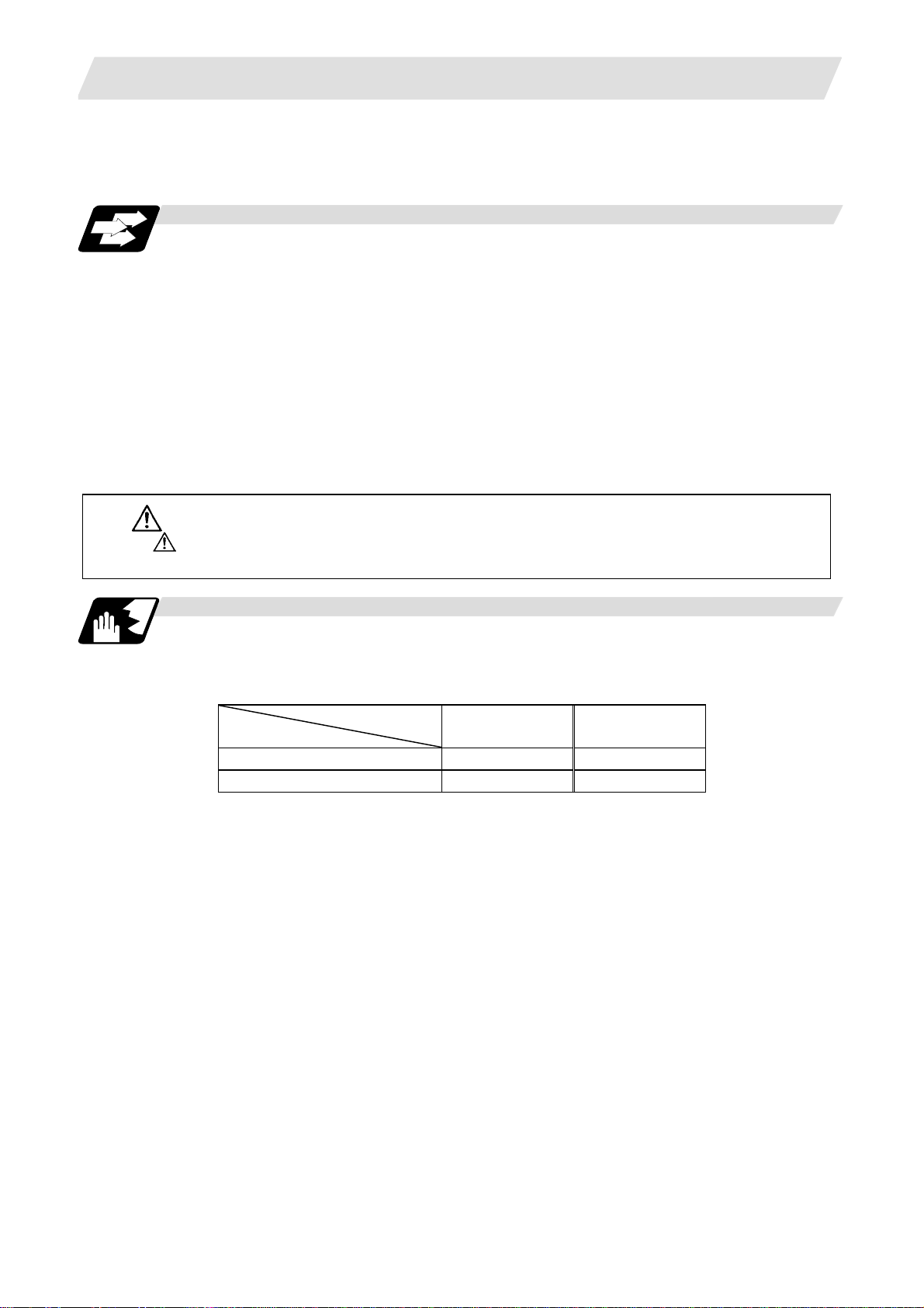
(2) G36
G36 is used for the two functions, automatic tool length measurement and circular
thread cutting (CCW). The applied function follows the parameter "#1238 set10/bit0"
(circular thread cutting) setting.
When "#1238 set10/bit0" is set to 0
G code Function
G35 Circular thread cutting clockwise rotation (CW)
G36 Automatic tool length measurement X
G37 Automatic tool length measurement Z
When "#1238 set10/bit0" is set to 1
G code Function
G35 Circular thread cutting clockwise rotation (CW)
G36 Circular thread cutting counterclockwise rotation (CCW)
G37 Automatic tool length measurement Z
CAUTION
The commands with "no value after G" will be handled as "G00".
22
Page 35

3. Data Formats
3.8 Precautions before Starting Machining
Precautions before machining
CAUTION
When creating the machining program, select the appropriate machining con ditions, and make
sure that the performance, capacity and limits of the machine and NC are not exceeded. The
examples do not consider the machining conditions.
Before starting actual machining, always carry out dry run operation to confirm the machining
program, tool offset amount and workpiece offset amount, etc.
3.8 Precautions before Starting Machining
23
Page 36

4. Buffer Register
A
A
4. Buffer Register
4.1 Input Buffer
Function and purpose
When the pre-read buffer is empty during a tape operation or RS-232C operation, the contents of
the input buffer are immediately transferred to the pre-read buffers, and provided that the data
stored in the input buffer do not exceed 250 × 4 characters, the following data (Max. 250
characters) are read and loaded into the input buffer.
This buffer is designed to eliminate the operational delay originating in the readout time of the tape
reader and to smooth out the block joints.
The pre-reading effects are lost, however, when the block execution time is shorter than the tape
readout time of the following block.
4.1 Input Buffer
Tape
Keyboard
(Buffer size: 250 × 5 characters)
Input buffer
Memory
MDI data
Mode
switching
Max. 5 execution blocks
Pre-read
buffer 5
Buffer 4
Buffer 3
Buffer 2
Buffer 1
Data equivalent to 1 block are
(Note)
stored in 1 pre-read buffer.
nalysis processing
rithmetic
processing
The input buffer has a memory capacity of 250 × 5 characters (including the EOB code).
(1) The contents of the input buffer register are updated in 250-character units.
(2) Only the significant codes in the significant data section are read into the input buffer.
(3) When codes (including "(" and ")") are sandwiched in the control in or control out mode and the
optional block skip function is ON, the data extending from the "/" (slash) code up to the EOB
code are read into the input buffer.
(4) The input buffer contents are cleared with resetting.
(Note 1) The input buffer size (250 characters) differs according to the model.
24
Page 37

4. Buffer Register
4.2 Pre-read Buffers
Function and purpose
During automatic processing, the contents of 1 block are normally pre-read so that program
analysis processing is conducted smoothly. However, during nose R compen sation, a maximum of
5 blocks are pre-read for the intersection point calculation including interference check.
The specifications of the data in 1 block are as follows:
(1) The data of 1 block are stored in this buffer.
(2) Only the significant codes in the significant data section are read into the pre-read buffer.
(3) When codes are sandwiched in the control in and control out, and the optional block skip
function is ON, the data extending from the "/" (slash) code up to the EOB code are not read
into the pre-read buffer.
(4) The pre-read buffer contents are cleared with resetting.
(5) When the single block function is ON during continuous operation, the pre-read buffer stores
the following block data and then stops operation.
Other precautions
(1) Depending on whether the program is executed continuously or by single blocks, the timing of
the valid/invalid for the external control signals for the optional block skip and others will differ.
4.2 Pre-read Buffers
(2) If the external control signal such as optional block skip is turned ON/OFF with the M command,
the external control operation will not be effective on the program pre-read with the buffer
register.
(3) According to the M command that operates the external controls, it prohibits pre-reading, and
the recalculation is as follows:
The M command that commands the external controls is distinguished at the PLC, and the
"recalculation request" for PLC → NC interface table is turned ON.
(When the "recalculation request" is ON, the program that has been pre-read is reprocessed.)
25
Page 38

5. Position Commands
X
5. Position Commands
5.1 Incremental/Absolute Value Commands
Function and purpose
There are 2 methods of issuing tool movement amount commands: the incremental value method
and the absolute value method.
The incremental value method applies for coordinates of a point which is to be moved and it issue s
a command using the distance from the present point; on the other hand, the absolute value
method issues a command using the distance from the coordinate zero point. The following figure
shows what happens when the tool is moved from point P1 to point P2.
5.1 Incremental/Absolute Value Commands
Spindle
Incremental value commands and absolute value commands for the X axis and Z axis are identified
by address when parameter "#1076 AbsInc" is set to 1, and identified by G code (G90/
G91) when set to 0. Similarly, even with additional axes (C axis or Y axis), they are differentiated by
addresses, or G code.
X axis
Z
P2
Workpiece coordinate zero point
Incremental and absolute value commands
W
P1
U
2
X
Z axis
Absolute value
Incremental value
(Example)
W ;
(Note 1) When parameter "#1076 AbsInc" is 1, and H is used for the incremental command
address, address H of blocks in M98, G114.2, and G10 L50 modal will be handled as the
parameter of each command, and the axis will not be moved.
X axis Address X
Z axis Address Z
C/Y axis Address C/Y
X axis Address U
Z axis Address W
C/Y axis Address H/V
Command method Remarks
• Set correspondence between
addresses and axes into "#1013
axname" and "#1014 incax".
• Absolute and incremental values can
be used together in the same block.
Incremental value command for Z axis
Absolute value command for X axis
26
Page 39

5. Position Commands
r2r
5.2 Radius/Diameter Commands
Function and purpose
The cross sections of workpieces machined on a lathe are circular, and the diameter or radius
value of those circles can be used for movement commands in the X-axis direction. A radius
command will move the tool by the commanded amount only, but a diameter command will move
the tool both in the X-axis direction by an amount equivalent to one-half the commanded amount
only and in the Z-axis direction by the commanded amount only.
This system permits radius or diameter commands to be issued, depending on the parameter
(#1019 dia) setting. The figure below shows the command procedure when the tool is to be moved
from point P1 to point P2.
X axis
5.2 Radius/Diameter Commands
P1
Spindle
P2
Workpiece coordinate zero point
1
Z axis
X command U command Remarks
Radius Diameter Radius Diameter
Even when a diameter command
has been selected, only the U
X = r1 X = 2r1 U = r2 U = 2r2
command can be made a radius
command by parameter "#1077
radius".
Radius and diameter commands
Precautions and Restrictions
(1) In the above example, the tool moves from P1 to P2 in the minus direction of the X axis and so
when an incremental value is issued, the minus sign is given to the numerical value being
commanded.
(2) In this manual, diameter commands are used in descriptions of both the X and U axes for the
sake of convenience.
27
Page 40

5. Position Commands
5.3 Inch/Metric Conversion; G20, G21
Function and purpose
The commands can be changed between inch and metric with the G20/G21 command.
Command format
G20/G21;
G20 Inch command
G21 Metric command
Detailed description
The G20 and G21 commands merely select the com mand units. They do not sel ect the Input units.
G20 and G21 selection is meaningful only for linear axes and it is meaningless for rotation axes.
Output unit, command unit and setting unit
The counter or parameter setting and display unit is determined by parameter "#1041 I_inch".
For the movement/speed command, the followings will be resulted:
The movement/speed command will be displayed as metric units when "#1041 I_inch" is ON during
the G21 command mode.
The internal unit metric data of the movement/speed command will be converted into an inch unit
and displayed when "#1041 I_inch" is OFF during the G20 command mode.
The command unit for when the power is turned ON and reset is decided by combining the
parameters "#1041 I_inch", "#1151 rstint" and "#1210 RstGmd/bit5".
NC axis
Movement/
speed command
Counter display Metric Metric Inch Inch
Speed display Metric Metric Inch Inch
User parameter
setting/display
Workpiece/
tool offset
setting/display
Handle feed
command
PLC axis
Movement/
speed command
Counter display Metric Inch
User parameter
setting/display
Item
Item
Initial inch OFF
(metric internal unit)
#1041 I_inch=0
G21 G20 G21 G20
Metric Inch Metric Inch
Metric Metric Inch Inch
Metric Metric Inch Inch
Metric Metric Inch Inch
#1042 pcinch=0
5.3 Inch/Metric Conversion
Initial inch ON
(inch internal unit)
#1041 I_inch=1
#1042 pcinch=1
(metric)
Metric Inch
Metric Inch
(inch)
28
Page 41

5. Position Commands
5.3 Inch/Metric Conversion
Precautions
(1) The parameter and tool data will be input/output with the "#1041 I_inch" setting unit.
If "#1041 I_inch" is not found in the parameter input data, the unit will follow the unit currently
set to NC.
(2) The unit of read/write used in PLC window is fixed to metric unit regardless of a parameter and
G20/G21 command modal.
(3) A program error (P33) will occur if G20/G21 command is issued in the same block as following
G code. Command in a separate block.
G7.1 (Cylindrical Interpolation)
G12.1 (Polar coordinate interpolation)
29
Page 42

5. Position Commands
5.4 Decimal Point Input
Function and purpose
This function enables the decimal point to be input. It assigns the decimal point in millimeter or inch
units for the machining program input information that defines the tool paths, distances and speeds.
A parameter "#1078 Decpt2" selects whether minimum input command increment (type I) or zero
point (type II) is to apply for the least significant digit of data without a decimal point.
Detailed description
(1) The decimal point command is valid for the distances, angles, times and speeds in machining
programs.
(2) Refer to the table rising the "Addresses used and valid/invalid decimal point commands" for
details on the valid addresses for the decimal point commands.
(3) In decimal point command, the valid range of command value is as shown below (for input
command increment cunit=10).
5.4 Decimal Point Input
Movement
Input unit
[mm]
Input unit
[inch]
(4) The decimal point command is valid even for commands defining the variable data used in
subprograms.
(5) Decimal point commands for decimal point invalid addre sses are processed as integer data
only and everything below the decimal point is ignored. Addresses which are invalid for the
decimal point are D, H, L, M, N, O, P, S and T.
All variable commands, however, are treated as data with decimal points.
Precautions
(1) If an arithmetic operator is inserted, the data will be handled as data with a decimal point.
(Example1) G00 X123+0 ;
command
(linear)
-99999.999 to
99999.999
-9999.9999 to
9999.9999
This is the X axis command 123mm command. It will not be 123μm.
Movement
command
(rotary)
-99999.999 to
99999.999
Feed rate Dwell
0. 001 to
10000000.000
0. 0001 to
1000000.0000
0 to 99999.999
30
Page 43

5. Position Commands
5.4 Decimal Point Input
Example of program
(1) Example of program for decimal point valid address
Program example
G0 X123.45
(decimal points are all mm points)
G0 X12345
#111 = 123, #112 = 5.55
X#111 Z#112
#113 = #111 + #112
(addition)
#114 = #111 - #112
(subtraction)
#115 = #111 ∗ #112
(multiplication)
#116 = #111/#112
#117 = #112/#111
(division)
Decimal point input I, II and decimal point command validity
In the table on the next page, decimal point input I and II result in the following for commands in
which a decimal point is not used in an address where a decimal point command is valid.
Both decimal point input I and II become the same for commands using a decimal point.
(1) Decimal point input I
The lowest order digit of command data matches the command unit.
(Example) When "X1" is commanded in 1μm system, the same result occurs as for an
Specification division
"X0.001" command.
Decimal point command 1
When 1 = 1μm When 1 = 10μm
X123.450mm X123.450mm X123.450mm
X12.345mm
(last digit is 1μm
unit)
X123.000mm,
Z5.550mm
#113 = 128.550 #113 = 128.550 #113 = 128.550
#114 = 117.450 #114 = 117.450 #114 = 117.450
#115 = 682.650 #115 = 682.650 #115 = 682.650
#116 = 22.162,
#117 = 0.045
X123.450mm X12345.000mm
X123.000mm,
Z5.550mm
#116 = 22.162,
#117 = 0.045
Decimal point
command 2
When 1 = 1mm
X123.000mm,
Z5.550mm
#116 = 22.162,
#117 = 0.045
(2) Decimal point input II
The lowest order digit of command data matches the command unit.
(Example) When "X1" is commanded in 1μm system, the same result occurs as for an "X1."
command.
31
Page 44

5. Position Commands
Addresses used, validity of decimal point commands
5.4 Decimal Point Input
Decimal
Add-
ress
point
command
Valid Coordinate position data
A
Invalid 2nd miscellaneous function
Valid Angle data
Invalid MRC program No.
Invalid Parameter input by
Valid Deep hole drilling cycle (2)
Valid Spindle synchronous
Valid Coordinate position data B
Invalid 2nd miscellaneous function
Valid Coordinate position data
C
Invalid 2nd miscellaneous function
Valid Corner chamfering amount ,C
Valid Program tool offset input
Valid Chamfering width (slitting
Valid Automatic tool length
D
Invalid Parameter input by
Invalid Synchronous spindle No. at
Valid Inch threads
Valid Corner cutting feed rate
Valid Feed rate F
Valid Thread lead
G Valid Preparatory function code
Valid Coordinate position data
H
Invalid Sequence Nos. in
Invalid Parameter input by
Invalid Selection of linear - arc
Invalid Basic spindle No. at spindle
Valid Circular center coordinates
I
Valid Nose R compensation/ tool
Valid Deep hole drilling (2)
Valid G0/G1 in-position width
Application
code
program, axis No.
Safety distance
acceleration/deceleration
time constant
code
code
Nose R compensation
amount (incremental)
cycle)
measurement,
deceleration range d
program, byte type data
spindle synchronization
Precision thread lead
subprograms
program, bit type data
intersection (geometric)
synchronization
radius compensation vector
components
First cut amount
Hole drilling cycle G0
in-position width
Re-
marks
E
,I
Add-
ress
J
K
L
M Invalid Miscellaneous function
O Invalid Program Nos.
P
(Note 1) Decimal points are all valid in user macro arguments.
Decimal
point
command
Valid Circular center coordinates
Valid Nose R compensation/ tool
Invalid Deep hole drilling (2)
Invalid Hole drilling cycle G1
Valid Circular center coordinates
Valid Nose R compensation/tool
Invalid Hole machining cycle
Valid Deep hole drilling cycle (2)
Valid Thread lead increase/
Invalid Subprogram
Invalid Program tool compensation
Invalid Parameter input by program,
Invalid Parameter input by program,
Invalid Synchronization
Invalid Tool life data
Invalid Sequence Nos. N
Invalid Parameter input by program,
Invalid Dwell time
Invalid Subprogram call program
Invalid 2nd, 3rd and 4th reference
Invalid Constant surface speed
Invalid MRC finishing shape start
Valid Cut-off cycle
Invalid Compound thread cutting
Valid Compound thread cutting
Invalid Program tool compensation
Application
radius compensation vector
components
Dwell at return point
in-position width
radius compensation vector
components
Number of repetitions
Second and subsequent cut
amounts
decrease amount (variable
lead thread cutting)
Number of repetitions
input type selection
selection
two-word type data
codes
data No.
Nos.
position No.
control, axis No.
sequence No.
shift amount/cut amount
cycle, number of cutting
passes, chamfering, tool
nose angle
cycle
Thread height
input compensation No.
Re-
marks
,J
L2
L10
L11
L70
4 bytes
32
Page 45

5. Position Commands
Decimal
Add-
ress
point
command
Invalid
P
Valid Coordinate position data
Invalid Skip signal command
Valid
Invalid
Invalid
Invalid Tool life data group No.
Invalid
Q
Invalid
Valid
Valid
Valid
Valid
Invalid
Invalid
Valid
Valid
Invalid
Valid R-designated arc radius
R
Valid
Valid
Valid
Invalid MRC shaping division No.
Valid
Valid
Valid
Valid
Valid
Parameter input by
program, section No.
Arc center coordinates
(absolute value)
(geometric)
Subprogram return
destination sequence No.
Extended workpiece
coordinate system No.
Minimum spindle clamp
rotation speed
MRC finishing shape end
sequence No.
Cut-off cycle
Cut amount/shift amount
Compound thread cutting
cycle
Minimum cut amount
Compound thread cutting
cycle
First cut amount
Deep hole drilling cycle 1
Cut amount of each pass
Program tool compensation
input
Hypothetical tool nose point
No.
Deep hole drilling cycle (2)
Dwell at cut point
Arc center coordinates
(absolute value)
(geometric)
Thread cutting start shift
angle
Tool life data management
method
Corner rounding circular
radius
Automatic tool length
measurement, deceleration
range r
MRC longitudinal/face
escape amount
Cut-off cycle, return
amount
Cut-off cycle, escape
amount
Compound thread cutting
cycle, finishing allowance
Compound thread cutting
cycle/turning cycle, taper
difference
Hole drilling cycle/deep
hole drilling cycle (2),
distance to R point
Application
Re-
marks
,R
5.4 Decimal Point Input
Decimal
Add-
ress
point
command
Valid
R
Valid Coordinate position data
Valid
Valid
Valid
Invalid Spindle function codes
S
Invalid
Invalid
Invalid
T Invalid Tool function codes
Valid Coordinate position data
U
Valid
Valid
Valid Dwell
Valid Coordinate position data V
Valid
W
Valid Coordinate position data
Valid
Valid
Valid Coordinate position data
X
Valid Dwell
Valid
Valid Coordinate position data Y
Valid
Valid Coordinate position data Z
Valid
Application
Program tool compensation
input/nose R compensation
amount
Rough cutting cycle
(longitudinal) (face) pull
amount
Synchronous tap/
asynchronous tap
changeover
Synchronous spindle phase
shift amount
Maximum spindle clamp
rotation speed
Constant surface speed
control, surface speed
Parameter input by
program, word type data
Program tool compensation
input
Rough cutting cycle
(longitudinal) cutting
amount
Program tool compensation
input
Program tool compensation
input
Rough cutting cycle (face)
cutting amount
Program tool compensation
input
Program tool compensation
input
Program tool compensation
input
Re-
marks
,R
2 bytes
(Note 1) Decimal points are all valid in user macro arguments.
33
Page 46

6. Interpolation Functions
6. Interpolation Functions
6.1 Positioning (Rapid Traverse); G00
Function and purpose
This command is accompanied by coordinate words. It positions the tool along a linear or
non-linear path from the present point as the start point to the end point which is specified by the
coordinate words.
Command format
G00 X__/U__ Z__/W__ ;
X, U, Z, W Coordinate values
The command addresses are valid for all additional axes.
Detailed description
(1) Once this command has been issued, the G00 mode is retained until it is changed by another
G function or until the G01, G02, G03, G33 or G34 command in the 01 group is issued. If the
next command is G00, all that is required is simply that the coordinate words be specified.
6.1 Positioning (Rapid Traverse)
(2) In he G00 mode, acceleration and deceleration are always carried out at the start point and end
point of the block. After confirming that the current block command is 0, the next block is
advanced to after confirming the state of the tracking error of the acceleration/deceleration circuit.
The in-position width is set with the parameters.
(3) Any G command (G83 to G89) in the 09 group is cancelled (G80) by the G00 command.
(4) Whether the tool moves along a linear or non-linear path is determined by parameter, but the
positioning time does not change.
(a) Linear path ................. This is the same as linear interpolation (G01), and the speed is
limited by the rapid traverse rate of each axis.
(b) Non-linear path.......... The tool is positioned at the rapid traverse rate independently for
each axis.
(5) When no number following the G address, this is treated as G00.
CAUTION
The commands with "no value after G" will be handled as "G00".
34
Page 47

6. Interpolation Functions
6.1 Positioning (Rapid Traverse)
Example of program
+X
Turret
Start point
(+180, +300)
End point (+100, +150)
Workpiece
+Z
(Unit : mm)
Chuck
G00 X100000 Z150000
; Absolute value command
G00 U-80000 W-150000 ; Incremental value command
(With an input setting unit of 0.001mm)
Precautions
(Note 1) When the parameter "#1086 G0Intp" is 0, the path along which the tool is positioned is the
shortest path connecting the start and end points. The positioning speed is automatically
calculated so that the shortest distribution time is obtained in order that the commanded
speeds for each axis do not exceed the rapid traverse rate.
When, for instance, the X-axis and Z-axis rapid traverse rates are both 9600mm/min, the
tool will follow the path in the figure below if the following is programmed:
G00 Z-300000 X400000 ; (With an input setting unit of 0.001mm)
End point
Actual X axis rate:
6400 mm/min
X
400
fx
Start
300
fz
point
(Unit : mm)
Actual Z axis rate: 9600 mm/m in
Z
35
Page 48

6. Interpolation Functions
(Note 2) When parameter "#1086 G0Intp" is 1, the tool will move along the path from the start point
to the end point at the rapid traverse rate of each axis.
When, for instance, the X-axis and Z-axis rapid traverse rates are both 9600 mm/min, the
tool will follow the path in the figure below if the following is programmed:
G00 Z − 300000 X400000 ; (With an input setting unit of 0.001mm)
End point
6.1 Positioning (Rapid Traverse)
Actual X axis rate:
9600 mm/min
400
X
fx
Z
Start
300
fz
point
(Unit : mm)
Actual Z axis rate: 9600 mm/ m in
36
Page 49

6. Interpolation Functions
A
A
(Note 3) The rapid traverse rate for each axis with the G00 command differs according to the
individual machine and so reference should be made to the machine specifications
manual.
(Note 4) Rapid traverse (G00) deceleration check
There are two methods for the deceleration check at rapid traverse; commanded
deceleration method and in-position check method. Select a method with the parameter
“#1193 inpos”.
■ When “inpos” = “1”
Upon completion of the rapid traverse (G00), the next block will be executed after
confirming that the remaining distances for each axis are below the fixed amounts. (Refer
to “Operation during in-position check”.)
The confirmation of the remaining distance should be done with the imposition width, L
L
The purpose of checking the rapid feed rate is to minimize the time it takes for po sitioning.
The bigger the setting value for the servo parameter "#2224 sv024", the longer the
reduced time is, but the remaining distance of the previous block at the starting time of the
next block also becomes larger, and this could become an obstacle in the actual
processing work. The check for the remaining distance is done at set intervals.
Accordingly, it may not be possible to get the actual amount of time reduction for
positioning with the setting value sv024.
■ When “inpos” = “0”
Upon completion of the rapid traverse (G00), the next block will be executed after the
deceleration check time (Td) has elapsed. The deceleration check time (Td) i s as follows,
depending on the acceleration/deceleration type.
(1) Linear acceleration/linear deceleration......................... Td = Ts + α
6.1 Positioning (Rapid Traverse)
is the setting value for the servo parameter "#2224 sv024".
R
.
R
Previous block
Ts
Td
cceleration/deceleration
Ts :
time constant
Td : Deceleration check time
Td = Ts + (0 to 14ms)
Next block
(2) Exponential acceleration/linear deceleration................ Td = 2 × Ts + α
Previous block Next block
2 × Ts
Td
Ts
cceleration/deceleration
Ts :
time constant
Td : Deceleration check time
Td = 2 × Ts + (0 to 14ms)
37
Page 50

6. Interpolation Functions
A
(3) Exponential acceleration/exponential deceleration...... Td = 2 × Ts + α
Previous block Next block
Where Ts is the acceleration time constant, α = 0 to 14ms
The time required for the deceleration check during rapid traverse is the longest among the
rapid traverse deceleration check times of each axis determined by the rapid traverse
acceleration/deceleration time constants and by the rapid traverse acceleration/
deceleration mode of the axes commanded simultaneously.
Ts
Td
6.1 Positioning (Rapid Traverse)
cceleration/deceleration
Ts :
time constant
Td : Deceleration check time
Td = 2 × Ts + (0 to 14ms)
38
Page 51

6. Interpolation Functions
6.1 Positioning (Rapid Traverse)
Programmable in-position width command for positioning
This command commands the in-position width for the positioning command from the machining
program.
G00 X__ Z__ ,I__ ;
In-position width
Positioning coordinate value of each axis
Operation during in-position check
Execution of the next block starts after confirming that the position error amount of the positioning
(rapid traverse: G00) command block and the block that carries out deceleration check with the
linear interpolation (G01) command is less than the in-position width issued in this command.
The in-position width in this command is valid only in the command block, so the deceleration check
method set in base specification parameter "#1193 inpos" is used for blocks that do not have the
in-position width command.
When there are several movement axes, the system confirms that the position error amount of
each movement axis in each part system is less than the in-position width issued in this com m and
before executing the next block.
The differences of when the in-position check is validated with the parameter (base specification
parameter "#1193 inpos" set to 1; refer to next page for in-position width) and when validated with
this command are shown below.
The differences of In-position check with parameter
In-position check with ",I" address command In-position check with parameter
After starting deceleration of the command system,
the position error amount and commanded
in-position width are compared.
After starting deceleration of the command system,
the servo system's position error amount and the
parameter setting value (in-position width) are
compared.
Block being
executed
Servo Command
In-position width
(Error amount of
command end point
and machine position)
Ts
Td
Block being
executed
Servo
Ts
Command
Td
In-position width
(Servo system position
error amount)
Start of in-position
check with parameter
Start of in-position check
with ",I" address command
Ts : Acceleration/deceleration time constant
Td : Deceleration check time
Td = Ts + (0 to 14ms)
39
Page 52

6. Interpolation Functions
A
A
6.1 Positioning (Rapid Traverse)
G0/G1 in-position width setting
When the setting value of the servo parameter "#2224 SV024" is smaller than the setting value of
the G0 in-position width "#2077 G0inps" and the G1 in-position width "#2078 G1inps", the
in-position check is carried out with the G0 in-position width and the G1 in-position width.
In-position check using the "G0inps"
value
Command to motor
Outline of motor movement
G0 in-position
SV024
stop is judged here.
In-position check using the "G1inps"
value
Command to motor
Outline of motor movement
G1 in-position
SV024
stop is judged here.
When the SV024 value is larger, the in-position check is completed when the error amount is
smaller than the SV024 setting value.
The in-position check method depends on the method set in the deceleration check parameter.
(Note 1) When the in-position width (programmable in-position check width) is set in the machining
program, either the in-position width set with the parameter (SV024, G0inps, G1inps) or
that set in the program, whichever larger, is applied when performing an in-position
check.
(Note 2) When the SV024 setting value is larger than the G0 in-position width/G1 in-position width,
the in-position check is carried out with the SV024 value.
(Note 3) When the error detection is ON, the in-position check is forcibly carried out.
40
Page 53

6. Interpolation Functions
6.2 Linear Interpolation
6.2 Linear Interpolation; G01
Function and purpose
This command is accompanied by coordinate words and a feed rate command. It makes the tool
move (interpolate) linearly from its present position to the end point specified by the coordinate
words at the speed specified by address F. In this case, the feed rate specified by address F always
acts as a linear speed in the tool nose center advance direction.
Command format
G01 X__/U__ Z__/W__ α__ F__ ,I__ ; ("α" is an additional axis)
X, U, Z, W, α
F
I
Coordinate values
Feed rate (mm/min or °/min)
In-position width. This is valid only in the commanded block. A block that
does not contain this address will follow the parameter "#1193 inpos"
settings. 1 to 999999 (mm)
X axis
Z
Command point
W
U
/
2
X
Detailed description
Once this command is issued, the mode is maintained until another G function (G00, G02, G03,
G33, G34) in the 01 group which changes the G01 mode is issued. Therefore, if the next command
is also G01 and if the feed rate is the same all that is required to be done is to specify the coordinate
words. If no F command is given in the first G01 command block, program error (P62) results.
The feed rate for a rotation axis is commanded by
°/min)
300
The G functions (G70 to G89) in the 09 group are cancelled (G80) by the G01 command.
Present position
Z axis
°/min (decimal point position unit). (F300 =
41
Page 54

6. Interpolation Functions
6.2 Linear Interpolation
Example of program
(Example 1)
X axis
20.0
Present position
Z axis
50.0
(Unit: mm)
G01 X50.0 Z20.0 F300 ;
(Example 2) Cutting in the sequence of P1 → P2 → P3 → P4 at 300mm/min feed rate
→ P1 , P4 → P0 is for tool positioning.
P0
Turret
+X
240
200
140
100
P1
P2
P3
P0
+Z
P4
Input setting unit : 0.001mm
2209040 230160
(Unit: mm)
G00 X200000 Z40000 ;
G01 X100000 Z90000 F300 ;
Z160000 ;
X140000 Z220000 ;
G00 X240000 Z230000 ;
P0
P1
P2
P3
P4
→ P1
→ P2
→ P3
→ P4
→ P0
42
Page 55

6. Interpolation Functions
6.2 Linear Interpolation
Programmable in-position width command for linear interpolation
This command commands the in-position width for the linear interpolation command from the
machining program.
The commanded in-position width is valid in the linear interpolation command only when carrying
out deceleration check.
• When the error detection switch is ON.
• When G09 (e xact stop che ck) is commanded in the same block.
• When G61 (exact stop check mode) is selected.
G01 X__ Z__ F__ ,I__ ;
In-position width
Feed rate
Linear interpolation coordinate value of each axis
(Note 1) Refer to section "6.1 Positioning (Rapid Traverse); G00" for details on the in-position
check operation.
43
Page 56

6. Interpolation Functions
r
6.3 Circular Interpolation; G02, G03
Function and purpose
These commands serve to move the tool along a circular.
Command format
G02 (G03) X__/U__ Z__/W__ I__ K__ F__ ;
G02 Clockwise (CW)
G03 Counterclockwise (CCW)
X/U Circular end point coordinates, X axis (absolute value of workpiece
Z/W Circular end point coordinates, Z axis (absolute value of workpiece
I Circular center, X axis (for I, incremental value of X coordinate at center as
K Circular center, Z axis (for K, incremental value of Z coordinate at cente r as
F Feed rate
coordinate system for X, incremental value from present position for U)
coordinate system for Z, incremental value from present position for W)
seen from start point. Command as “radius command”.)
seen from start point)
The circular center coordinate value is commanded with an input setting increment. Caution is
required for the arc command of an axis for witch the input command increment differs. Com mand
with a decimal point to avoid confusion.
6.3 Circular Interpolation
X axis
End point
U/2
X
Z K
Cente
I
Start
point
W
Z axis
44
Page 57

6. Interpolation Functions
Detailed description
(1) G02 (or G03) is retained until another G command (G00, G01 or G33) in the 01 group that
changes its mode is issued.
The direction of the circular rotation is differentiated by G02 and G03:
G02 : Clockwise (CW)
G03 : Counterclockwise (CCW)
+X
Chuck
CCW(G03)
6.3 Circular Interpolation
Turret
+X
CW(G02)
Workpiece
CCW(G03)
+X
(2) An arc which extends for more than one quadrant can be executed with a single block
command.
(3) The following information is needed for circular interpolation.
(a) Rotation direction :Clockwise (G02) or counterclockwise (G03)
(b) Circular end point coordinates :Given by addresses X, Z, U, W
(c) Circular center coordinates :Given by addresses I, K (incremental value commands)
CW(G02)
Turret
+Z
+Z
+Z
+X
(d) Feed rate :Given by address F
(4) A program error results when I, K or R is not commanded.
Consideration must be given to the sign for I and K since I is the distance in the X-axis direction
to the arc center as seen from the start point and K is the distance in the Z-axis direction.
(5) No T commands can be issued in the G2/G3 modal status.
A program error (P151) results if a T command is issued in the G2/G3 modal status.
45
Page 58

6. Interpolation Functions
Example of program
6.3 Circular Interpolation
Workpiece
coordinate
zero point
G2 X120.0 Z70.0 I50.0 F200 ; Absolute value command
G2 U100.0 W-50.0 I50.0 F200 ; Incremental value command
X axis
50.0
120.0
20.0
Z axis
70.0 50.0
(Unit: mm)
46
Page 59

6. Interpolation Functions
Change into linear interpolation command
Program error (P33) will occur when the center and radius are not designated at circular command.
When the parameter "#11029 Arc to G1 no Cent (Change comm and from arc to linea r when no arc
center designation)" is set, the linear interpolation can be applied to terminal coordinates value for
only the block. However, a modal is the circular modal.
This function is not applied to a circular command by a geometric function.
(Example) The parameter "#11029 Arc to G1 no Cent (Change command from arc to linear when
no arc center designation)" = "1"
N1
6.3 Circular Interpolation
G90 X0 Y0 ;
N1 G02 X20. I10. F500 ;
N2 G00 X0;
N3 G02 X20. F500 ;
M02 ;
… (a)
… (b)
N3
0
20
(a) The circular interpolation (G02) is executed because there is a center command.
(b) The linear interpolation (G01) is executed because there is no center and radius command.
47
Page 60

6. Interpolation Functions
;
Δ
A
p
;
t
6.3 Circular Interpolation
Cautions for circular interpolation
(1) The terms "clockwise" (G02) and "counterclockwise" (G03) used for circular operations are
defined as a case where in a right-hand coordinate system, the negative direction is viewed
from the positive direction of the coordinate axis which is at right angles to the plane in
question.
(2) If all the end point coordinates are omitted or the end point is at the same position as the start
point, commanding the center using I and K is the same as commanding a 360
circle).
(3) The following occurs when the start and end point radii do not match in a circular command:
(a) Program error (P70) results at the circular start point when error
parameter "#1084 RadErr".
G02Z80.K50.
X
larm stop
Start
point
(b) Spiral interpolation in the direction of the commanded end point results when error
less than the parameter value.
Start
oint radius
Center End point
End point
Z
radius
ΔR is greater than the
R
° arc (perfect
ΔR is
G02Z90.K50.
Spiral interpolation
X
End
Z
Center
End poin
radius
Start
Start point radius
point
point
R
Δ
48
Page 61

6. Interpolation Functions
6.4 R Specification Circular Interpolation
6.4 R Specification Circular Interpolation; G02, G03
Function and purpose
Along with the conventional circular interpolation commands based on the circular center
coordinate (I, K) designation, these commands can also be issued by directly designating the
circular radius R.
Command format
G02 (G03) X/U__ Z/W__ R__ F__ ;
X/U
Z/W
R
F
The arc radius is commanded with an input setting increment. Caution is required for the arc
command of an axis for which the input command increment differs. Command with a decimal point
to avoid confusion.
Detailed description
The circular center is on the bisector line which is perpendicular to the line connecting the start and
end points of the circular. The point, where the circular with the specified radiu s whose start point is
the center intersects the perpendicular bisecto r line, serves as the center coordinates of the circular
command.
If the R sign of the commanded program is plus, the circular is smaller than a semicircular; if it is
minus, the circular is larger than a semicircular.
X-axis end point coordinate
Z-axis end point coordinate
Circular radius
Feed rate
Circular path when R sign is minus
02
Center
point
L
Start point
The following condition must be met with an R specification circular interpolation command:
Where L is the line from the start point to end point.
If an R specification and I, K specification are given at the same time in the same block, the circular
command with the R specification takes precedence.
In the case of a full-circle command (where the start and end points coincide), an R specification
circular command will be completed immediately even if it is issued and no operation will be
executed. An I, K specification circular command should therefore be used in such a case.
L
2 × r
When L/2 - r > (parameter : #1084 RadErr), an alarm will occur.
≤ 1
r
Center point
01
End point
Circular path when R sign is plus
49
Page 62

6. Interpolation Functions
6.4 R Specification Circular Interpolation
Example of program
(Example 1)
G03 Zz1 Xx1 Rr1 Ff1 ; R specification circular on Z-X plane
(Example 2)
G02 Xx1 Zz1 Ii1 Kk1 Rr1 Ff1 ; R specification circular on X-Z plane
(When the R specification and I, K specification are
contained in the same block, the R specification has
priority in processing.)
Circular center coordinate compensation
When "the error margin between the segment connecting the start and end points" and "the
commanded radius × 2" is less than the setting value because the required semicircle is not
obtained by calculation error in R specification circular interpolation, "the midpoint of segment
connecting the start and end points" is compensated as the circular center.
Set the setting value to the parameter "#11028 Tolerance Arc Cent (Tolerable correction value of
arc center error)".
(Ex.) "#11028 Tolerance Arc Cent" = "0.000 (mm)"
Setting value Tolerance value
Setting value< 0 0(Center error will not be interpolated)
Setting value= 0
Setting value> 0 Setting value
2×minimum setting increment
G90 X0 Y0 ;
N1 G02 X10. R5.000;
N1, N3
N
0
10
N2 G0 X0;
N3 G02 X10. R5.001;
N4 G0 X0;
N5 G02 X10. R5.002;
N6 G0 X0;
M02 ;
… (a)
… (b)
(a) Compensate the center coordinate: Same as N1 path
(b) Do not compensate the center coordinate: Inside path a little than N1
Calculation error margin compensation allowance value: 0.002 mm
Segment connecting the start and end paints: 10.000
N3: Radius × 2 = 10.002 "Error 0.002 -> Compensate"
N5: Radius × 2 = 10.004 "Error 0.004 -> Do not compensate"
Therefore, this example is shown in the above figure.
50
Page 63

6. Interpolation Functions
6.5 Plane Selection; G17, G18, G19
Function and purpose
These commands are used to select the control plane and the plane on which the circular exists.
If the 3 basic axes and the parallel axes corresponding to these basic axes are entered as
parameters, the commands can select the plane composed of any 2 axes which are not parallel
axes. If a rotation axis is entered as a parallel axis, the commands can select the plane containing
the rotation axis.
These commands are used to select:
• The plane for circular interpolation
• The plane for nose R compensation
Command format
G17;
G18;
G19;
I, J and K indicate each basic axis or parallel axis.
When the power is turned ON or when the system is reset, the plane set by the p arameters "#1025
I_plane" is selected.
(I-J plane selection)
(K-I plane selection)
(J-K plane selection)
6.5 Plane Selection
I
G03
G02
J
G17 (I-J) plane G18 (K-I) plane G19 (J-K) plane
K
G03
G02
I
J
G03
G02
K
51
Page 64

6. Interpolation Functions
6.5 Plane Selection
Parameter entry
#1026 to 1028
base_I, J, K
I X Y
J Y
K Z
Fig. 1 Examples of plane selection
parameter entry
Plane selection system
This section describes the plane selection for the parameter entry samples shown in Fig. 1.
(1) Axis addresses assigned in the same block as the plane selection (G17, G18, G19) command
determine which of the basic axes or parallel axes are to be in the actual plane selected.
(Example)
#1029 to 1031
aux_I, J, K
Basic axes and parallel axes can be entered in
the parameters. The same axis name can be
entered in duplication, but when it is assigned in
duplication, the plane is determined by plane
selection system (4).
It is not possible to set axes, which have not
been entered, as control axes.
Y
G17XY;
G03
X
G18XZ;
G03
Z
G19YZ;
G03
G02
X
(2) Plane selection is not performed with blocks in which the plane selection G code (G17, G18,
G19) is not assigned.
G18 X_ Z_ ; Z-X plane
Y_ Z_ ; Z-X plane (no plane change)
(3) When the axis addresses are omitted in the block containing the plane selection G codes (G17,
G18, G19), it is assumed that the axis addresses of the 3 basic axes have been assigned.
G18 ; (Z-X plane = G18 XZ ;)
(4) When the basic axes or their parallel axes are duplicated and assigned in the same block as
the plane selection G code (G17, G18, G19), the plane is determined in the order of basic axes,
and then parallel axes.
G18 XYZ ; The Z-X plane is selected.
Therefore, the Y movement is unrelated to the selected plane.
(Note 1) When the "2" in the parameter "#1025 I_plane" is kept ON, the G18 plane is selected
when the power is turned ON or when the system is reset.
G02
G02
Z
Y
52
Page 65

6. Interpolation Functions
δ
δ
6.6 Thread Cutting
6.6.1 Constant Lead Thread Cutting; G33
Function and purpose
The G33 command exercises feed control over the tool which is synchronized with the spindle
rotation and so this makes it possible to conduct constant-lead straight thread-cutting, tapered
thread-cutting, and continuous thread-cutting.
F/E
6.6 Thread Cutting
F/E
F/E
Straight thread Scrolled thread Continuous thread
Command format
G33 Z/W__ X/U__ F__ Q__ ; (Normal lead thread cutting commands)
Z, W, X, U
F
Q
Thread end point
Lead of long axis (axis which moves most) direction
Thread cutting start shift angle, 0.001 to 360.000
°
G33 Z/W__ X/U__ E__ Q__ ; (Precision lead thread cutting commands)
Z, W, X, U
E
Q
Thread end point
Lead of long axis (axis which moves most) direction
Thread cutting start shift angle, 0.001 to 360.000
°
X axis
End
point
U/2
δ2
1
One-rotation synchronization signal
Q
Z axis
Start point
Thread cutting start position
Z
X
Z
> Illegal lead at start of thread cutting
1
δ
> Illegal lead at end of thread cutting
2
W
F/E
53
Page 66

6. Interpolation Functions
6.6 Thread Cutting
Detailed description
(1) The E command is also used for the number of ridges in inch thread cutting, and whether the
number of ridges or precision lead is to be designated can be selected by parameter setting.
(Parameter "#1229 set 01/bit" is set to "1" for precision lead designation.)
(2) The lead in the long axis direction is commanded for the taper thread lead.
X axis
When a < 45
When a > 45
When a = 45
End
point
U/2
°, Lead is in Z-axis direction.
°, Lead is in X-axis direction.
°, Lead can be in either Z or X-axis direction.
W
Tapered thread section
a°
Start point
Z axis
Thread cutting metric input
Input
setting unit
Command
address
Least
command
increment
Command
range
Input
setting unit
Command
address
Least
command
increment
Command
range
B (0.001mm) C (0.0001mm)
F (mm/rev) E (mm/rev) E (ridges/inch) F (mm/rev) E (mm/rev) E (ridges/inch)
1 (=1.000),
(1.=1.000)
0.001 to
999.999
F (mm/rev) E (mm/rev) E (ridges/inch) F (mm/rev) E (mm/rev) E (ridges/inch)
1 (= 1.00000),
(1.=1.00000)
0.00001 to
999.99999
1 (= 1.00000),
(1.=1.00000)
0.00001 to
999.99999
D (0.00001mm) E (0.000001mm)
1 (= 1.0000000),
(1.=1.0000000)
0.0000001 to
999.9999999
1 (= 1.00),
(1.=1.00)
0.03 to
999.99
1 (= 1.0000),
(1.=1.0000)
0.2550 to
999.9999
1 (= 1.0000),
(1.=1.0000)
0.0001 to
999.9999
1 (= 1.000000),
(1.=1.000000)
0.000001 to
999.999999
1(=1.000000),
(1.=1.000000)
0.000001 to
999.999999
1 (=1.00000000),
(1.=1.00000000)
0.00000001 to
999.99999999
1 (= 1.000),
(1.=1.000)
0.255 to
999.999
1 (= 1.00000),
(1.=1.00000)
0.25500 to
999.99999
54
Page 67

6. Interpolation Functions
Thread cutting inch input
6.6 Thread Cutting
Input
setting unit
Command
address
Least
command
increment
Command
range
Input
setting unit
Command
address
Least
command
increment
Command
range
B (0.0001inch) C (0.00001inch)
F (inch/rev) E (inch/rev) E (ridges/inch) F (inch/rev) E (inch/rev) E (ridges/inch)
1(=1.0000),
(1.=1.0000)
0.0001 to
99.9999
F (inch/rev) E (inch/rev) E (ridges/inch) F (inch/rev) E (inch/rev) E (ridges/inch)
1 (= 1.000000),
(1.=1.000000)
0.000001 to
99.999999
1(=1.000000),
(1.=1.000000)
0.000001 to
39.370078
D (0.000001inch) E (0.0000001inch)
1 (= 1.00000000),
(1.=1.00000000)
0.00000001 to
39.37007874
1 (= 1.0000),
(1.=1.0000)
0.0255 to
9999.9999
1 (= 1.000000),
(1.=1.000000)
0.025500 to
9999.99999
1(=1.00000),
(1.=1.00000)
0.00001 to
99.99999
1 (= 1.0000000),
(1.=1.0000000)
0.0000001 to
99.9999999
1(=1.0000000),
(1.=1.0000000)
0.0000001 to
39.3700787
1 (= 1.000000000),
(1.=1.000000000)
0.000000001 to
39.370078740
1(=1.00000),
(1.=1.00000)
0.25401 to
9999.99999
1 (= 1.0000000),
(1.=1.0000000)
0.0255000 to
9999.9999999
(Note 1) It is not possible to assign a lead where the feed rate as converted into feed per minute
exceeds the maximum cutting feed rate.
(3) The constant surface speed control function should not be used for taper thread cutting
commands or scrolled thread cutting commands.
(4) The spindle rotation speed should be kept constant throughout from the rough cutting until the
finishing.
(5) If the feed hold function is employed during thread cutting to stop the feed, the thread ridges
will lose their shape. For this reason, feed hold does not function during thread cutting.
Note that this is valid from the time the thread cutting command is executed to the time the axis
moves.
If the feed hold switch is pressed during thread cutting, block stop will result at the end point of
the block following the block in which thread cutting is completed (no longer G33 mode).
(6) The converted cutting feed rate is compared with the cutting feed clamp rate when thread
cutting starts, and if it is found to exceed the clamp rate, an operation error will result.
(7) In order to protect the lead during thread cutting, a cutting feed rate which has be en converted
may sometimes exceed the cutting feed clamp rate.
(8) An illegal lead is normally produced at the start of the thread and at the end of the cutting
because of servo system delay and other such factors.
Therefore, it is necessary to command a thread length which is determined by adding the
illegal lead lengths
δ1 and δ2 to the required thread length.
(9) The spindle rotation speed is subject to the following restriction:
≤ R ≤
1
Where R
Maximum feed rate
Thread lead
≤ Tolerable speed of encoder (r/min)
R = Spindle rotation speed (r/min)
Thread lead = mm or inches
Maximum feed rate = mm/min or inch/mm
(this is subject to the restrictions imposed by the machine specifications).
(10) A program error (P97) may occur when the result of the expression (9) is R<1 because the
thread lead is very large to the highest cutting feedrate.
55
Page 68

6. Interpolation Functions
(11) Dry run is valid for thread cutting but the feed rate based on dry run is not synchronized with the
spindle rotation.
The dry run signal is checked at the start of thread cutting and any switching during thread
cutting is ignored.
(12) Synchronous feed applies for the thread cutting commands even with an asynchronous feed
command (G94).
(13) Spindle override and cutting feed override are invalid and the speeds are fixed to 100% du ring
thread cutting.
(14) When a thread cutting command is programmed during nose R compensation, the
compensation is temporarily canceled and the thread cutting is executed.
(15) When the mode is switched to another automatic mode while G33 is executed, the following
block which does not contain a thread cutting command is first executed and then the
automatic operation stops.
(16) When the mode is switched to the manual mode while G33 is executed, the following block
which does not contain a thread cutting command is first executed and then the automatic
operation stops. In the case of a single block, the following block which does not contain a
thread cutting command (When G33 mode is cancelled) is first executed and then the
automatic operation stops. Note that automatic operation is stopped until the G33 command
axis starts moving.
6.6 Thread Cutting
(17) The thread cutting comma nd waits for the single rotati on sync signal of the rotary encoder and
starts movement.
Note that carry out synchronization between part systems before issuing a thread cutting
command with multiple part systems. For example, when using the 1-spindle specifications
with multi-part systems, if one part system issues a thread cutting command during ongoing
thread cutting by another part system, the movement will start without waiting for the rotary
encoder single rotation sync signal.
(18) The threa d cutting start shift angle is not a modal. If there is no Q command with G33, this will
be handled as "Q0".
(19) The automatic handle interrupt/interruption is valid during thread cutting.
(20) If a value exceeding 360.000 is commanded with G33 Q, a program error (P35) will occur.
(21) G33 cuts one row with one cycle. To cut two rows, change the Q value, and issue the same
command.
56
Page 69

6. Interpolation Functions
6.6 Thread Cutting
Example of program
X axis
20.0
90.0
40.0 50.0
G33 X90.0 Z40.0 E12.34567 ; Absolute valu e command
G33 U70.0 W-50.0 E12.34567 ; Incremental value command
(Unit: mm)
Z axis
57
Page 70

6. Interpolation Functions
δ1δ
6.6.2 Inch Thread Cutting; G33
Function and purpose
If the number of ridges per inch in the long axis direction is assigned in the G33 command, the feed
of the tool synchronized with the spindle rotation will be controlled, whi ch means that constant-lead
straight thread-cutting and tapered thread-cutting can be performed.
Command format
G33 Z/W__ X/U__ E__ Q__ ;
Z,W,X,U
E
Q
6.6 Thread Cutting
Thread end point
Number of ridges per inch in direction of long axis (axis which moves
most) (decimal point command can also be assigned)
Thread cutting start shift angle, 0.001 to 360.000
°
X axis
End
point
Z
> Illegal lead at start of thread cutting
1
δ
> Illegal lead at end of thread cutting
2
U/2
Z
δ2
W
X
F/E
Z axis
Start point
One-rotation synchronization signal
Q
Thread cutting start position
Detailed description
(1) The number of ridges in the long axis direction is assigned as the number of ridges per inch.
(2) The E code is also used to assign the precision lead length, and whether the number of ridge s
or precision lead length is to be designated can be sel ected by parameter setting. (The number
of ridges is designated by setting parameter "#1229 set 01/bit 1" to "0".)
(3) The E command value should be set within the lead value range when the lead is converted.
(4) See Section "6.6.1 Constant lead thread cutting" for other details.
58
Page 71

6. Interpolation Functions
6.6 Thread Cutting
Example of program
X axis
40.0 50.0
20.0
90.0
(Unit: mm)
Z axis
G33 X90.0 Z40.0 E12.0 ; Absolute value command
G33 U70.0 W-50.0 E12.0 ; Incremental value command
59
Page 72

6. Interpolation Functions
6.6.3 Continuous Thread Cutting
Function and purpose
Continuous thread cutting is possible by assigning thread cutting commands co ntinuously.
In this way, it is possible to cut special threads whose lead or shape changes.
6.6 Thread Cutting
G33
Command format
G33 Zz1/Ww1 Xx1/Uu1 Ff1/Ee1 Qq1 ;
(G33) Zz2/Ww2 Xx2/Uu2 Ff2/Ee2 Qq2 ;
(G33) Zz3/Ww3 Xx3/Uu3 Ff3/Ee3 Qq3 ;
Zzn, Wwn, Xxn, Uun
Ffn/Een
Qqn
Detailed description
(1) The first thread cutting block in the continuous thread cutting command waits for the spindle's
single rotation synchronization signal before starting thread cutting. From the second and
following blocks, movement starts without waiting for the spindle's single rotation
synchronization command.
Thus, the thread cutting start shift angle (Q) can be commanded only in the first block.
(2) The G33 command can be omitted from the second and following blocks.
(3) When commanding continuous thread cutting, command the thread cutting commands in
successive blocks. If a command other than thread cutting is issue d, continuous thread cutting
will not take place.
Note that if a command that does not involve axis movement (G4 dwell command, MST
command, etc.) is commanded between the thread cutting command blocks, whether to wait
for the spindle's single rotation synchronization signal after the 2nd block can be selected with
the parameters.
Thread end point
Lead of long axis (axis which moves most) direction
Thread cutting start shift angle, 0.001 to 360.000
G33
G33
°
# Item Contents Setting range
1270 ext06/
bit6
(4) The other matters are the same as uniform lead thread cutting.
Set the continuous thread cutting Z phase wait operation.
0: If there is no movement command (MST command, etc.)
between the thread cutting locks, the 2nd block thread
cutting waits for the spindle's single rotation synchronization
signal before starting movement.
1: Even if there is no movement command (MST command,
etc.) between the thread cutting blocks, the 2nd block thread
cutting starts movement without waiting for the spindle's
single rotation synchronization signal.
60
0/1
Page 73

6. Interpolation Functions
6.6.4 Variable Lead Thread Cutting; G34
Function and purpose
Variable lead thread cutting is enabled by a command specifying a lead increment or decrement
amount per turn of the screw.
Command format
G34 X/U__ Z/W__ F/E__ K__ ;
X/U Z/W
F/E
K
Thread end point
Standard screw lead
Lead increment or decrement amount per turn of the screw
Non-lead axis
6.6 Thread Cutting
Lead axis
F+3.5K
Lead speed
F+4K
F+2.5K F+1.5K F+0.5K
F+3K F+2K F+K F
61
Page 74

6. Interpolation Functions
6.6 Thread Cutting
Detailed description
(1) The command range is as shown below.
Thread cutting metric input
Input
setting unit
Command
address
Least
command
increment
Command
range
Input
setting unit
Command
address
Least
command
increment
Command
range
F (mm/rev) E (mm/rev) F (mm/rev) E (mm/rev)
1 (=1.000),
(1.=1.000)
0.001 to
999.999
F (mm/rev) E (mm/rev) F (mm/rev) E (mm/rev)
1 (= 1.00000),
(1.=1.00000)
0.00001 to
999.99999
B (0.001mm) C (0.0001mm)
1 (= 1.00000),
(1.=1.00000)
0.00001 to
999.99999
D (0.00001mm) E (0.000001mm) B/C/D/E
1 (= 1.0000000),
(1.=1.0000000)
0.0000001 to
999.9999999
1 (= 1.0000),
(1.=1.0000)
0.0001 to
999.9999
1 (= 1.000000),
(1.=1.000000)
0.000001 to
999.999999
1(=1.000000),
(1.=1.000000)
0.000001 to
999.999999
1 (=1.00000000),
(1.=1.00000000)
0.00000001 to
999.99999999
K (n ∗ mm/rev)
n: Number of
pitches
Same as F or E
(signed)
Thread cutting inch input
Input
setting unit
Command
address
Least
command
increment
Command
range
Input
setting unit
Command
address
Least
command
increment
Command
range
1(=1.0000),
(1.=1.0000)
0.0001 to
99.9999
1 (= 1.000000),
(1.=1.000000)
0.000001 to
99.999999
B (0.0001inch) C (0.00001inch)
F (inch/rev) E (inch/rev) F (inch/rev) E (inch/rev)
1(=1.000000),
(1.=1.000000)
0.000001 to
39.370078
D (0.000001inch) E (0.0000001inch) B/C/D/E
F (inch/rev) E (inch/rev) F (inch/rev) E (inch/rev)
1 (= 1.00000000),
(1.=1.00000000)
0.00000001 to
39.37007874
1(=1.00000),
(1.=1.00000)
0.00001 to
99.99999
1 (= 1.0000000),
(1.=1.0000000)
0.0000001 to
99.9999999
1(=1.0000000),
(1.=1.0000000)
0.0000001 to
39.3700787
1 (= 1.000000000),
(1.=1.000000000)
0.000000001 to
39.370078740
K (n ∗ inch/rev)
n: Number of
pitches
Same as F or E
(signed)
(2) A positive value of K indicates incremental pitches.
Movement amount of one block (n pitches) = (F + K) + (F + 2K) + (F + 3K) + · · + (F + nK)
(3) A negative value of K indicates decremental pitches.
Movement amount of one block (n pitches) = (F – K) + (F – 2K) + (F – 3K) + · · + (F – nK)
62
Page 75

6. Interpolation Functions
(4) A program error will occur if the thread lead is not set correctly.
Error No. Meaning Remedy
P93
(Reference 1) Last lead =
Number of pitches = (–F + last lead)/K
Z: Length of lead axis
(5) The other matters are the same as G33.
Refer to section "6.6.1 Constant lead thread cutting; G33".
Illegal pitch value
(1) An invalid value is specified for F/E
or K in a thread cutting command.
(2) The last lead goes outside of the F/E
command range.
(F2+2KZ)
6.6 Thread Cutting
Specify valid values for F/E and
K.
(Reference 1)
63
Page 76

6. Interpolation Functions
6.6.5 Circular Thread Cutting; G35, G36
Function and purpose
Circular thread cutting making the longitudinal direction the lead is possible.
Command format
G35(G36) X/U__ Z/W__ {
G35
G36
X/U
Z/W
I
K
R
F/E
Q
Clockwise (CW)
Counterclockwise (CCW)
Circular end point coordinate, X axis (absolute value of workpiece
coordinate system for X, incremental value from present position for U)
Circular end point coordinate, Z axis (absolute value of workpiece
coordinate system for Z, incremental value from present position for W)
Circular center, X axis (incremental value of circular center looking
from start point)
Circular center, Z axis (incremental value of circular center looking
from start point)
Arc radius
Longitudinal (axis with largest movement amount) direction lead
(F.. normal lead thread cutting/E .. precision lead thread, inch thread)
Thread cutting start shift angle, 0.000 to 360.000°
X axis
End point
U/2
I__ K__
R__
Z
} F/E__ Q__ ;
W
6.6 Thread Cutting
Start point
X
R
Center
K
l
Z axis
F/E
Circular thread
64
Page 77

6. Interpolation Functions
6.6 Thread Cutting
Detailed description
(1) A program error (P33) will occur if the start point and end point match or if the arc center angle
is more than 180°.
(2) The following will occur if the start point radius and end point radius do not match.
• A program error (P70) will occur if the error ΔR is more than parameter "#1084 RadErr" (arc
error).
• Interpolation will start from the arc center where the start point radius and end point radius
match if the error
ΔR is less than parameter "#1084 RadErr".
Start point
radius
End point
End point radius
Obtained center
Center
ΔR
Start point
(3) A program error (P33) will occur if the R_ sign is negative.
(4) A program error (P33) will occur if there is no I_K_ command and R_ command.
(5) The R_ command will have the priority if the I_K_ command and R_ command are issued in
the same block.
(6) If the arc center is (0,0), the arc command can be issued for two successive quadrants. A
program error (P33) will occur if an arc with more than three quadrants is issued.
When Z axis is long axis
1st and 4th quadrant 2nd and 3rd quadrant
X
Start poin t End point
Center
Z
Start point E nd point
X
Center
Z
65
Page 78

6. Interpolation Functions
(7) When the movement amount is equal, the horizontal direction in the sele cte d plane will be th e
long axis.
Plane selection Long axis when movement amount is equal
G17 (XY plane) I axis
G18 (ZX plane) K axis
G19 (YZ plane) J axis
(8) G36 is used to command two functions, automatic tool length measurement and circular thread
cutting (CCW). Which function is selected follows parameter "#1238 set10/bit0" (Arc thread
cutting).
When #1238 set10/bit0 is set to 0
G code Function
G35 Circular thread cutting clockwise (CW)
G36 Automatic tool length measurement X
When #1238 set10/bit0 is set to 1
G code Function
G35 Circular thread cutting clockwise (CW)
G36 Circular thread cutting counterclockwise (CCW)
G37 Automatic tool length measurement Z
G37.1 Automatic tool length measurement X
G37.2 Automatic tool length measurement Z
(9) If the lead axis and non-lead axis cutting feed rate is faster than the clamp speed when threa d
cutting is started, the "M01 operation error 107" will occur, and thread cutting will not start.
6.6 Thread Cutting
(10) During thread cutting, the cutting feed rate may exceed the clamp speed to guarantee the lead.
In this case, the error "M01 operation error 107" will appear, but thread cutting will continue.
However, if the "cutting feed rate > clamp speed" is established during circular thread cutting
commanded in the second or following block of continuous thread cu tting, automatic operation
will be stopped just before the circular thread cutting command in the 2nd block, and the error
"M01 operation error 107" will appear.
(11) Continuous thread cutting is possible by commanding the thread cutting command in
succession. This allows special threads in which the leads or shapes change midway to be cut.
The continuous thread cutting command can be issued in the order of arc
constant lead, and constant lead
(12) Normally, an illegal lead will be cut at the start and end of the threads, due to a delay in the
servo system.
Thus, command the required thread length with the illegal thread length added to the start and
end.
As another method, command the required thread length as a circular thread (G35/G36), and
then command the illegal lead length before and after that command (start and end of thread
cutting) as a constant lead thread (G33). (Continuous thread cutting in order of constant lead
→ arc → constant lead.)
→ arc.
→ arc, arc →
66
Page 79

6. Interpolation Functions
6.6 Thread Cutting
Relation with other functions
(1) A program error (P113) will occur if the G35/G36 command is issued to an axis not within the
selected plane.
(2) The thread cutting speed is not synchronized with the spindle rotation when dry run is valid.
(The thread pitch is not guaranteed.)
(3) If the dry run switch is turned ON during thread cutting, the dry run signal will be ignored.
(4) If the FEEDHOLD switch is pressed during thread cutting, the block will stop at the end point of
the block following that in which thread cutting is completed (when the thread cutting mode is
exited).
(5) Circular thread cutting will function normally even during mirror image.
(6) A program error (P201) will occur if the G35/G36 circular thread cutting command is issued in
the finish shape program of the compound type fixed cycle for turning machining.
(7) A program error (P385) will occur if thread cutting corner rounding or corner chamfering is
commanded during circular thread cutting or the next block.
(8) Geometric and circular thread cutting cannot be co mmanded simultaneously. If commanded
simultaneously, a program error (P395) or program error (P70) will occur.
(9) If thread cutting is commanded during nose R compensation, nose R compensation will be
tempor arily canceled, and thread cutting will be executed.
(10) Do not issue the circular thread cutting command during constant surface speed control. The
thread will not be cut correctly because the spindle rotation speed will change during thread
cutting.
Precautions
(1) Spindle override does not function during thread cutting.
(2) A program error (P39) will occur if G35 /G36 is commanded when the additional specifications
are not provided.
67
Page 80

6. Interpolation Functions
X
6.7 Helical Interpolation; G17, G18, G19, and G02, G03
Function and purpose
This function is for circularly interpolating 2 axes on the selected plane and simultaneously
interpolating the other axis linearly in synchronization with the circular motion. When this
interpolation is performed with 3 orthogonal axes, the tool will travel helically.
6.7 Helical Interpolation
Z
Y
Circular interpolation element
Command program path
Linear interpolation element
Command format
G17 G02 (G03) X/U__ Y/V__ Z/W__ I__ J__ F__ ;
G17 G02 (G03) X/U__ Y/V__ Z/W__ R__ F__ ;
G17 Arc plane (G17: X-Y plane, G18: Z-X plane, G19: Y-Z plane)
G02 (G03) Arc rotation direction (G02: clockwise, G03: counterclockwise)
X/U, Y/V Arc end point coordinates
Z/W Linear axis end point coordinates
I, J Arc center coordinates
R Arc radius
F Feed rate
(Note 1) In this manual, the following setting descriptions are used: I axis: X, J axis: Y, K axis: Z
68
Page 81

6. Interpolation Functions
X
j
6.7 Helical Interpolation
Detailed description
The following type of movement will take place when the following type of command is issued.
G17 G02 Xx Yy Zz Ii Jj Ff ;
Z
Command program path
Y
Linear interpolation element
Circular interpolation element
Y
End point
X
i
Start point
X-Y plane path (projected path)
The left drawing shows the process as an exploded view, and the right drawing shows the arc plane
from directly above.
69
Page 82

6. Interpolation Functions
X
6.7 Helical Interpolation
Example of program
(Example)
G17 G02 X100. Y100. Z100. I-100. J100. F120 ;
Z
Circular interpolation element
Command program pat h
Y
Linear interpolation elem ent
Y
End point
X
J100.
I-100.
Start point
X-Y plane path (projected path)
(Unit: mm)
The left drawing shows the process as an exploded view, and the right drawi ng shows the arc
plane from directly above.
At the start of the block, the axis centers at the point –100mm in the X axis direction and
100mm in the Y axis direction from the workpiece coordinates (start point), and starts cutting at
the feed rate 120mm/min while rotating.
Precautions and restrictions
(1) When executing helical interpolation, command another linear axis (several axis can be
commanded) that does not contain the circular interpolation comma nd and arc axis.
(2) Up to the number of simultaneous contouring control axes can be commanded simultaneously.
(3) A command exceeding one rotation cannot be issued. (The circular interpolation command
specifications are followed.)
(4) Command the feed rate as the composite speed for each axis.
(5) With helical interpolation, the axis that configures the plane is the circular interpolation axis,
and the other axes are the linear interpolation axes.
(6) The corner chamfering or corner R commands that are issued before or after the helical
interpolation command block are effective only on the axes contained in the selected plane.
(7) For the parameters and error messages, refer to the materials concerning the circular
interpolation (G02,G03).
70
Page 83

6. Interpolation Functions
6.8 Milling Interpolation; G12.1
Function and purpose
Milling interpolation is used to perform contouring control by converting commands programmed in
an orthogonal coordinate system into movements of a linear axis and rotation axis (workpiece
rotation).
6.8 Milling Interpolation
Y (Hypothetical axis)
X
Z
C
A G12.1 command is issued to perform milling and a G13.1 command is issued to cancel milling
and returns to normal turning.
Command format
G12.1 D__ E__ ; Milling mode ON
D Selection of milling hypothetical axis name
E Designation of milling interpolation rotation axis
G13.1; Milling mode OFF (Turning mode)
71
Page 84

6. Interpolation Functions
Address Meaning of address
D Selection of milling
hypothetical axis
name
E Designation of
milling interpolation
rotation axis
The following G codes are used to select milling and set the conditions.
Command range
(unit)
0: Y axis
1: Rotation axis
name
G12.1 command
system rotation axis
command address
6.8 Milling Interpolation
Remarks
• If there is no D command, the
milling hypothetical axis name
will follow parameter (#1517
mill_C).
• If only the D command is issued,
it will be handled as D0.
• A program error (P35) will occur
if a value other than 0 or 1 is
issued as the numerical
command after the D command.
• If there is no E command, the
parameter (#1516 mill_ax) will be
followed.
• A program error (P33) will occur
if only an E command is issued.
• A program error (P33) will occur
if an axis address is not
commanded after "E=".
• A program error (P 300) will occur
if an axis that does not exist in
the command system is
designated as the rotation axis
name.
• A program error (P32) will occur
if a value is commanded for the
rotation axis name.
• To issue a program command
after the "E= rotation axis name",
delimit the "E= rotation axis
name" and the other command
with a comma (,). A program
error (P33) will occur if there is
no comma.
G code Function Remarks
G12.1 Milling mode ON Default is G13.1.
G13.1 Milling mode OFF
G16 Selection of Y-Z cylindrical plane
G17 Selection of X-Y plane
G19 Selection of Y-Z plane
G41 Tool radius compensation left Default is G40.
G42 Tool radius compensation right
72
One of G17, G16, and G19 can be
defined as the default (when G12.1
is issued) by the parameter.
Page 85

6. Interpolation Functions
Machining mode
6.8 Milling Interpolation
G13.1 (Turning mode) G12.1 (Milling mode)
G17
(X-Y plane)
G46, G41, G42/G40 (Nose R compensation) G41, G42/G40 (Tool compensation)
G18
(Z-X plane)
6.8.1 Selecting Milling Mode
Detailed description
(1) The G12.1 and G13.1 commands are used to switch between the turning (G13.1) and milling
(G12.1) modes.
(2) These commands are modal and the initial mode effective at power ON is the turning mode.
G19
(Y-Z plane)
G16
Y-Z
cylindrical
plane
G17
(X-Y plane)
G19
(Y-Z plane)
(3) The following requirements must be satisfied before a G12.1 command is issued. Otherwise, a
program error (P485) results.
(a) Nose R compensation has been canceled.
(b) Constant surface speed control has been canceled.
(4) If one of the command axes in the milling mode has not completed reference position return, a
program error (P484) results.
(5) The G12.1 command automatically cancels an asynchronous mode F command. Therefore,
specify an F value in milling mode.
(Note1) If G12.1 is executed, while no movement command has been given, after nose R
compensation is canceled by an independent G40 command, nose R compensation is
canceled in the G12.1 block.
(Note2) If the milling interpolation command is issued during the mirror image, a program error
(P486) results.
(Note3) When the G12.1 command is issued, the deceleration check is executed.
(Note 4) If a command other than a plane section is issued during the G12.1 comm and, a program
error (P33) will occur.
73
Page 86

6. Interpolation Functions
6.8.2 Milling Interpolation Control and Command Axes
6.8 Milling Interpolation
Detailed description
(1) The two orthogonal linear axes (X axis and Z axis) and a rotation axis are used as control axes
for milling interpolation. The rotation axis is selected with the E command. The axis designated
with the parameter will be selected if there is no E command.
(2) Three orthogonal linear axes are used as the command axes for milling interpolation. They are
the X, Z, and a hypothetical axis.
The hypothetical axis is a hypothetical axis for interpolation which intersects the X and Z axes
at right angles. The hypothetical axis name is the control rotation axis name selected with Y or
in (1) with the D command. The axis name designated with the parameter will be selected if
there is no D command.
(Hypothetical axis)
X
Z
(3) Command axis X for milling is not just the interpolated one of control axis X. It is handled as X
in the milling coordinate system when a G12. 1 command is issued.
(4) Whether the position in the milling coordinate system is a diameter command or radius
command is selected with the following parameter.
Parameter Details
#8111 Milling Radius
0: Radius command for all axes
1: Follows parameter (#1019 dia) for each axis
(Example 1)
Hypothetical axis
X
20
N3
10
0 10
When C axis is used for rotation axis, and
"Y" is used for hypothetical axis name
(Program 1)
:
:
:
N1 G0 X40 ;
N2 G12.1 ;
(or G12.1 E=C, D0 ;)
N3 G1 X10. Y10. F10. ;
:
:
:
(Unit: mm)
74
Page 87

6. Interpolation Functions
N3 of program 1 is executed as follows:
6.8 Milling Interpolation
Hypothetical
axis
(a)
(d)
Hypothetical
axis
X = Mill _ X
Program path
X
Program path
1010
Hypothetical
axis
Mill _ X
Hypothetical
axis
X
Mill _ X
(b)
Program path
X
(c)
Mill _ X
Program path
(Unit: mm)
Current values
X 28.284 (diameter value display)
C 45.000
(5) Milling interpolation is also available for a two-control-axis system consisting of one linear axis
and one rotation axis. The X axis must be used as the linear axis. The rotation and milling
hypothetical axes are selected as shown above. In milling mode, the G17 plane must be
selected.
(6) The table below lists the incremental axis names of the hypothetical axis used in milling mode.
These axis commands handle radius commands only.
Selected hypothetical
axis
Absolute axis name Incremental axis name
Y axis Y V
Rotation axis (C) Rotation axis name (C) Rotation axis incremental name (H)
(The following description uses Y for the hypothetical axis name and C for the rotation axis
name.)
75
Page 88

6. Interpolation Functions
6.8.3 Selecting a Plane during the Milling Mode
Function and purpose
A plane selection command decides the plane on whi ch the to ol moves for circular interpolation or
tool radius compensation in milling mode.
Command format
G17/G19 ;
G16 C__ ;
G16 Y-Z cylindrical plane
C Cylindrical radius value
G17 X-Y plane
G19 Y-Z plane
(1) These G commands for plane selection are modal. The G17 plane is automatically selected as
the default each time the turning mode is switched to the milling mode by a G12.1 command.
When the milling mode is switched back to the turning mode by a G13.1 command, the plane
that was selected before the milling mode is entered is restored.
6.8 Milling Interpolation
(2) G16 or G19 can also be defined as the default effective when a G12.1 command is issued. A
parameter is used for this.
(3) The three planes selected are explained below.
(a) G16
G16 indicates the plane obtained by developing a cylinder with its bottom radius X. This is
useful to process the side face of a workpiece.
X
Z
Y
Y-Z cylindrical plane
76
Page 89

6. Interpolation Functions
Y
(b) G17
G17 is an X-Y plane in an XYZ orthogonal coordinate system. This is useful to process the
end face of a workpiece.
X
6.8 Milling Interpolation
Z
X-Y plane
(c) G19
G19 is a Y-Z plane in an XYZ orthogonal coordinate system.
X
Z
Center of workpiece
Y
Y-Z plane
77
Page 90

6. Interpolation Functions
6.8.4 Setting Milling Coordinate System
Function and purpose
The coordinate system for the milling mode is set according to the selected plane each time the
turning mode (G13.1) is switched to the milling mode by a G12.1 command.
G17 and G19 planes
(1) For the X and Z axes, the current positions are set as radius value on the coordinate value.
(2) The Y axis is decided as the axis which intersects the X and Z axes at right angles. Y=0 is
defined in a G12.1 command.
6.8 Milling Interpolation
Tool
Y
X
Z
(Note1) During the milling mode on the G17 plane, the X axis is operated in the area (positive or
negative side) that has existed before issuing the G12.1 command. When you want to control
the X axis in the positive side during the milling mode, moving the X axis to the positive area
(including 0) is required before issuing the G12.1 command. When you want to control the X
axis in the negative side during the milling mode, moving the X axis to the negative area (not
including 0) is required before issuing the G12.1 command.
G16 plane
(1) To select a G16 plane, the radius value of a cylinder is specified by "G16 C__ ;". If no radius
value is specified, the current X axis value is used as the radius value to define a cylinder. If no
radius value can be defined, a program error (P485) occurs.
(2) As in normal turning mode, the X axis indicates the distance from the center line of the
workpiece.
(3) G16 (Y-Z cylindrical plane) is actually the side of a cylinder.
(4) The X axis indicates the distance from the center line of the workpiece. The Y axis indicates the
circumference with the radius value of the bottom of a cylinder defined by a G16 command.
78
Page 91

6. Interpolation Functions
(5) The zero point of the Y axis is the position where a G12.1 command is issued.
(Example)
6.8 Milling Interpolation
:
:
G12.1 G16 C50. ;
:
:
:
or
:
:
G12.1 ;
G16 C50. ;
:
:
:
:
G12.1 Ee,Dd ;
or
G16 C50. ;
:
:
:
:
G12.1 Ee,Dd ;
or
G16 C50. ;
:
:
Y
X
r
Z
79
Page 92

6. Interpolation Functions
6.8.5 Preparatory Functions
Valid G codes in milling m ode
Classifi-
cation
G code Function
G00 Positioning G65 Macro call
∗
G01 Linear interpolation G66 Macro modal call A
∗
G02 Circular interpolation (CW) G66.1 Macro modal call B
∗
G03 Circular interpolation (CCW) G67 Macro modal call cancel
∗
G04 Dwell
G09 Exact stop check G80 Hole drilling cycle cancel
G83 Deep hole drilling cycle (Z axis)
G13.1 Turning mode G84 Tap cycle (Z axis)
G85 Boring cycle (Z axis)
G87 Deep hole drilling cycle (X axis)
G16 Y-Z cylindrical plane selection G88 Tap cycle (X axis)
G17 X-Y plane selection G89 Boring cycle (X axis)
G90 Absolute value command
G19 Y-Z plane selection G91 Incremental value command
G22 Barrier check ON G94 Asynchronous feed
G23 Barrier check OFF
G98
G99 Hole drilling cycle R point return
G61 Exact stop mode
G40
G41 Tool radius compensation left G64 Turning mode
G42 Tool radius compensation right
Tool radius compensation
cancel
6.8 Milling Interpolation
Classifi-
cation
G code Function
Hole drilling cycle initial point
return
∗ : Milling interpolation command
: G code effective only in milling mode
(1) If an invalid G code is issued in milling mode, a program error (P481) occurs.
If the milling interpolation is commanded in milling mode, a program error (P481) occurs.
(2) In milling mode, all movement commands are commanded with the coordinate system
determined by the selected machining plane. The rotation axis thus cannot be moved by a
direct command in milling mode. To perform milling at a specific position of a workpiece,
therefore, positioning must have been made in turning mode.
(Example)
:
:
G0 X100. C180.;
⇒ Positioning before milling
G12.1; (or G12.1 E=C,D0;)
G0 X50.;
:
:
(3) If a command for an axis other than X, Z, and Y (rotation axis) is issued in milling mode, a
program error (P481) occurs. The asynchronous tap can be used during the milling mode;
however, the synchronous tap must not be commanded.
80
Page 93

6. Interpolation Functions
(4) In milling mode, the Y axis can be specified by only four G codes: G00, G01, G02, and G03.
These are called the milling interpolation commands.
(5) The G84, G88 synchronous tapping cycles cannot be used during the milling mode.
Positioning (G00)
If a G00 command is issued in milling mode, positioning is made to the specified point on the
selected plane at a rapid traverse rate.
G00 X/U__ Y/V__ Z/W__ ;
Linear interpolation (G01)
If a G01 command is issued in milling mode, linear interpolation is made to the specified point on
the selected plane at the speed specified by an F speed.
(1) G16 mode
Program format
6.8 Milling Interpolation
G01 Y/V__ Z/W__ X/U__ F__ ;
S
y
Y
z
Z
E
Development
S
y
z
X
E
81
Page 94

6. Interpolation Functions
A
(2) G17 mode
Program format
6.8 Milling Interpolation
G01 X/U__ Y/V__ Z/W__ F__ ;
(3) G19 mode
Program format
G01 Y/V__ Z/W__ X/U__ F__ ;
E
Y
X
x
S
y
z
E
Z
X
E
x
S
y
Y
z
Z
A
E
82
Page 95

6. Interpolation Functions
6.8 Milling Interpolation
Circular interpolation (G02/G03)
If a G02 or G03 command is issued in milling mode, circular interpolation is performed at the
specified speed on the selected plane.
(1) G16 mode
G02/G03 Y/V__ Z/W__ J__ K__ F__ ;
or
G02/G03 Y/V__ Z/W__ R__ F__ ;
G02 Circular interpolation (clockwise)
G03 Circular interpolation (counterclockwise)
Y/V Circular end point coordinate, Y axis (Y: absolute value, V:
incremental value)
Z/W Circular end point coordinate, Z axis (Z: absolute value, W:
incremental value)
J/K Circular center incremental value (radius command
incremental value from the start point to the center)
R Circular radius
F Feed rate
E
(A, Q)
E
Y
S
Development
(A, Q) k
Z
X
Z
j
S
83
Page 96

6. Interpolation Functions
(2) G17 mode
G02/G03 X/U__ Y/V__ I__ J__ F__ ;
or
G02/G03 X/U__ Y/V__ R__ F__ ;
X/U Circular end point coordinate, X axis (X: absolute value, U:
Y/V Circular end point coordinate, Y axis (Y: absolute value, V:
I/J Circular center incremental value (incremental value from the
R Circular radius
F Feed rate
incremental value)
incremental value)
start point to the center)
X
6.8 Milling Interpolation
Q
Z
Y
(A, Q)
i
S
j
E
A
(3) G19 mode
G02/G03 Y/V__ Z/W__ J__ K__ F__ ;
or
G02/G03 Y/V__ Z/W__ R__ F__ ;
Y/V Circular end point coordinate, Y axis (Y: absolute value, V:
incremental value)
Z/W Circular end point coordinate, Z axis (Z: absolute value, W:
incremental value)
J/K Circular center incremental value (incremental value from the
start point to the center)
R Circular radius
F Feed rate
Y
X
A
j
k
S
Q
Z
E
84
Page 97

6. Interpolation Functions
6.8.6 Switching from Milling Mode to Turning Mode; G13.1
Detailed description
(1) A G13.1 command is used to cancel the milling mode and return to the turning mode.
(2) The G13.1 command is effective if the following requirement is met. If not, a program error
(P485) occurs.
(a) Tool radius compensation has been canceled.
(3) The G13.1 command restores the plane selected before the preceding G12.1 command was
issued.
(4) The G13.1 command restores the mode (synchronous or asynchronous) and the F value (if in
asynchronous mode) selected before the preceding G12.1 command was issued.
(Note 1) If G13.1 is executed, while no movement command has been given, after cancellation by
an independent G40 command, tool radius compensation is canceled in the G13.1 block.
(Note 2) When G13.1 command is issued, the deceleratio n check is executed.
(Note 3) If another command is issued during the G13.1 command, a program error will occur.
6.8.7 Feed Function
Asynchronous cutting feed
An asynchronous feed mode (G94 command) can use F6.3 digits to specify the feed rate per
minute in units of 0.001mm/min. The specifiable range is 0.001 to 999999.999mm/min. If the
effective speed exceeds the cutting feed clamp speed, it is clamped by that clamp speed.
(Note 1) Whenever the turning mode is switched to the milling mode by a G12.1 command, the F
command modal value is canceled. After mode change, therefore, the feed rate must be
set by an F command.
(Note 2) A G12.1 command forces the mode to shift to the asynchronous mode.
(Note 3) When the milling mode is canceled by a G13.1 command, both the feed mode and F
command modal value return to the original state before the preceding G12.1 command
was issued.
6.8.8 Program Support Functions
Relation with other functions
The following program support functions are effective in milling mode:
(1) Linear angle command
(2) Variable command
(3) Automatic corner chamfering/corner rounding
(4) Geometric function
(5) Hole drilling cycle
(6) Subprogram function
(7) User macro
6.8 Milling Interpolation
85
Page 98

6. Interpolation Functions
6.8.9 Miscellaneous Functions
Relation with other functions
(1) M and B commands can be issued in milling mode.
(2) In milling mode, an S command specifies not the spindle rotation speed but the rotary tool
speed.
(3) If a T command is issued in milling mode, a program error (P485) occurs. Before a G12.1
command is issued, therefore, tool selection must be done.
:
T1212 ;
G0 X100. Z0. ;
G12.1 ; (or G12.1 E=C,DO ;)
:
T1200 ;
(P485).
:
G13.1 ;
(4) Complete the tool compensation operation (movement of tool length and wear compensation
amount) before executing the milling interpolation. If the tool compensation operation is not
completed when the milling interpolation start command has been issued, the followings will be
resulted:
Machine coordinate is not changed even if G12.1 is executed.
The workpiece coordinate is changed to that of the post tool length compensation when
G12.1 is executed. (Even if canceling the milling interpolation, this workpiece coordinate will
not be canceled.)
6.8 Milling Interpolation
⇒ Specify a T command before a G12.1 command.
⇒ In milling mode, a T command causes a program error
(Example)
Workpiece coordinate offset (X axis)=20.
Tool compensation amount of T0101 (X axis)=100.
Setting compensation operation with movement command after T command
<Machining
program>
: [X axis] [C axis] [X axis] [C axis]
G00 X200. C0.; 200. 0. 220. 0.
T0101; 200. 0. 220. 0.
G12.1; 100. 0. 220. 0. <-The workpiece coordinate system
G01 X50. F1000; 50. 0. 170. 0.
:
<Workpiece
coordinate>
<Machine
coordinate>
is shifted (without moving the axis)
86
Page 99

6. Interpolation Functions
A
6.8.10 Tool Offset Functions
Tool length offset
(1) In milling mode, tool compensation is performed by adding the tool length offset amount
specified on the cutting coordinates converted from the milling coordinate system.
6.8 Milling Interpolation
X
: Tool position
Tool position
Tool length offset
X
Y
X
Y
Y
Y
Milling coordinate system
ctual tool position
X
Movement on the milling
coordinate system
87
Page 100

6. Interpolation Functions
A
(2) As in (1) on previous page, if the offset amount is different from the actual one, the shape is not
corrected normally.
(a) If the offset amount is larger than tool length:
Example: The actual tool length is 15.0 when tool length X = 20.0
6.8 Milling Interpolation
Y
X
Milling command
ctual shape
Tool movement
88
 Loading...