

Disposal
2 CE2 6 3
Dispose the unusable device according to valid regulations.
Disposal of spent batteries/accumulators
You are required by law to return all spent batteries. Disposing of used
batteries with domestic waste is prohibited!
Batteries / NiCad cells containing toxins are marked by
accompanying symbols that refer to the prohibition of
disposal with domestic waste. The designations for the
decisive heavy metals are: Cd=cadmium, Hg=mercury,
Pb=lead. You may return spent batteries/accumulators free
2005-08-13
By doing so, you fulfil the legal requirements and contribute to the
conservation of our environment!
of charge to the recycling centres, our outlets or anywhere
else where batteries/accumulators are sold.
Digital Wireless Microphone Systems
Digital Wireless Microphone Systems
Instruction Manual
ACT-8H : DIGITAL WIRELESS HANDHELD MICROPHONE
ACT- 8T : DIGITAL WIRELESS BODY PACK TRANSMITTER
Electronics Co., Ltd.
Head office: 814, Pei-Kang Road, Chiayi, 60096, Taiwan.
Taipei office: 5, Lane 118, Sung-teh Road, 10075, Taipei, Taiwan.
Web-http: //www.mipro.com.tw
E-mail: mipro@mipro.com.tw
DIGITAL WIRELESS HANDHELD MICROPHONE
ACT-8H DIGITAL WIRELESS HANDHELD MICROPHONE
DIGITAL WIRELESS HANDHELD MICROPHONE
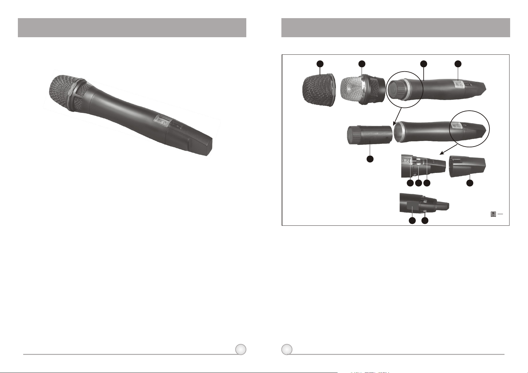
1. Part Names and Functions
1 2 3 4
Main features:
1. The world's first 24-bit true digital handheld wireless microphone, combining
the best design and the most advanced features.
2. Magnesium alloy housing offers a comfortable feel, balanced weight
allocation and special surface finishing, giving it a truly professional
appearance and quality.
3. Available in three colors: black, rose metallic and blue diamond. Custommade colors are also available for special requirements.
4. Anti-roll & anti-pop microphone capsule module with extremely low touch
noise characteristics.
5. Optional interchangeable microphone capsule modules.
6. Bright LCD display shows working channel, battery status, input level and
error codes.
7. Integrated antenna provides maximum transmission efficiency and the
patented color rear caps protect the on/off as well as the audio sensitivity
switches while providing easy channel identification.
8. Built-in and detachable lithium-polymer (Li-Poly) battery pack can be
recharged alone or together with the transmitter. Eight continuous hours of
operation are possible due to its compact size and high-efficiency circuitry
design.
9. Second generation of the world's first ACT function rapidly and precisely sets
up the transmitter frequency.
1
5
SET
OFF
MODE
7
86 9
()
1110
1. Upper Grille: Provides access & protection to capsule.
2. Capsule Module: Metal grille integrated to protect the capsule.
3. Housing: Houses various PCB and Li-Poly battery module.
4. LCD Display Panel: Displays group, frequency, gain, battery level, input SPL and
error code.
5. Lithium-Polymer Battery Back: Built-in and detachable Li-Poly battery module can
be recharged alone or together with transmitter; gives 8 hours continuous
operation time.
6. Power Switch: Switch to ''ON'' when using microphone and ''OFF'' position when
not.
7. MODE: Mode selection button.
8. SET: Parameter selection button.
9. Color Rear Cap: Designed to protect the ON/OFF switch to help prevent the user
turning off the microphone during use.
10. ACT Receptor: Signal reception via the ACT function; automatically programs the
frequency and the encryption code from the receiver.
11. Battery Charging Contact: For charging battery module.
2
DIGITAL WIRELESS HANDHELD MICROPHONE
DIGITAL WIRELESS HANDHELD MICROPHONE
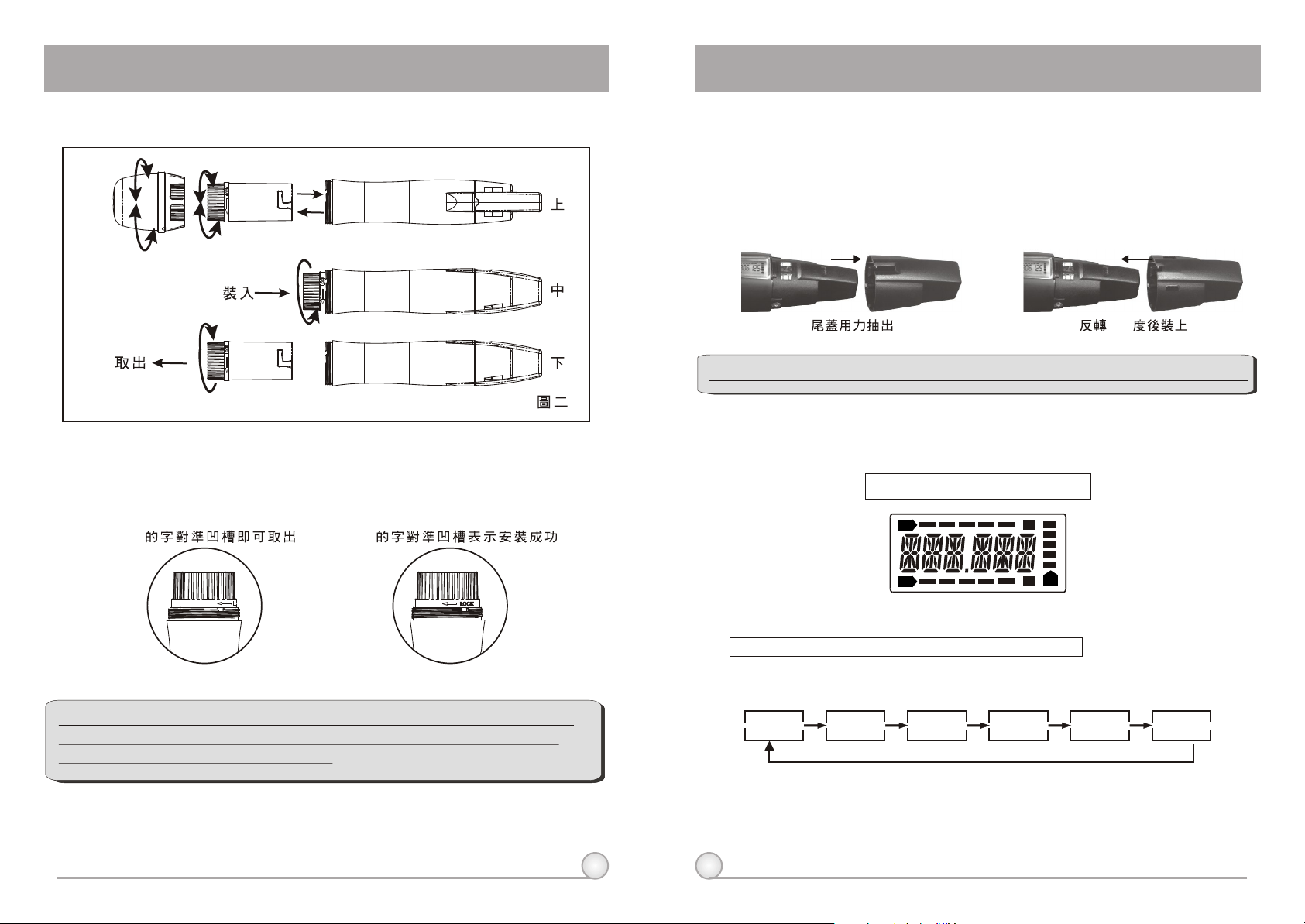
2. Battery Removals and Installation
()
Open the upper grille and capsule module, then turning the battery pack
in a counterclockwise direction in order to replace the battery (see diagram 2).
To reinstall the battery module after loading the new battery, turn it in a
clockwise direction (see diagram 2).
OPEN LOCK
3. Rear Cap On/Off Switch Protection
The patented color rear cap serves two purposes, provides easy channel
identification and protecting the toggle on/off switch. It allows the on/off switch
to either be exposed or concealed as desired. You can avoid unintended
switching off of the microphone by rotating the color rear cap 180 degrees to
cover the on/off switch completely.
180
**Note: When using the microphone, the color rear cap must be in place.
4. LCD Panel Functions
Fully Lit VFD Display
RF
A
**NOTE: When microphone is not in use, please turn the power off.
Battery pack can be recharged while in the transmitter or remove
from transmitter and charged alone.
B
AF
BT
Function Selection:
Mode Switch: To select from different menu
The LCD panel has 6 functions displayed sequentially; their respective
descriptions and operations are as follows:
FREQ LOW--CU
AF--SEN
LIMIT ENCRYPGR--CH
A. Operation Guide
a. Press MODE (7) to access the 6 different functions. Once a function is selected, it
starts flashing on the screen. If parameter needs to be modified on selected
function, press SET (8) to modify the value while the display is still flashing. Once
3
4
done, leave it for 5 seconds until it stops flashing and the selection will be
programmed into the transmitter.

DIGITAL WIRELESS HANDHELD MICROPHONE
DIGITAL WIRELESS HANDHELD MICROPHONE
(1)GR-CH: Displays Information of Group and Channel
RF
AF
BT
5
RF
AF
BT
A. Operate via MODE Button
MODE
GR--CH
B. Operation Guide:
a. Press ''MODE'' and stop on "GR-CH" function, the display showing current group
and channel will be flashing. After 5 seconds, the display will stop flashing.
b. "GR-CH" function is added to display group and channel information. Changing
current group and channel must be done on the receiver.
**NOTE: When program a special frequency via monitoring software;
LCD screen cannot display the number. This is because this special
channel is not in the preset group and channel. Therefore, LCD panel
will look like illustration below.
A. Operate via MODE Button
MODE
FREQ
B. Operation Guide:
a. Press ''MODE'' and stop on "FREQ" function, the display showing current
frequency will be flashing. After 5 seconds, the display will stop flashing.
B. "FREQ" function is added to display frequency information. Changing current
frequency must be done on the receiver.
**NOTE: To modify transmitter's group, channel and frequency, all
three must be set at the receiver and transmit the new setting to
transmitter via ACT.
(3) LOW-CU: Setup and Change of Low Frequency Cut Off
SET OFF
SET ON
RF
AF
BT
5
RF RF
AF AF
BT BT
RF
AF
BT
RF
AF
(2) FREQ: Displays Information of Transmitter Frequency
RF
AF
BT
5
"MHz"
RF
AF
BT
BT
A. Operate via MODE Button
MODE
LOW--CU
OFF
ON
SET
B. Operation Guide:
a. Press ''MODE'' and stop on "LOW-CU" function, the display showing current state
will be flashing and is ready to be modified.
b. Press ''SET'' button to change to ''ON'' or ''OFF'' as desired.
**NOTE: When the LOW-CU function is ''ON'', the frequency response
below 100Hz will decrease about 4dB with a slope of -6dB/Octave.
5
6
5

DIGITAL WIRELESS HANDHELD MICROPHONE
DIGITAL WIRELESS HANDHELD MICROPHONE
(4) AF-SEN: Setup and Change of Input Sensitivity
SET 6dB
RF
AF
BT
RF RF
AF AF
BT BT
5
A. Operate via MODE Button
MODE
AF--SEN
0 DB
SET
6 DB
SET
12 DB
SET
B. Operation Guide:
a. Press "MODE" and stop on "AF-SEN" function, the display showing current state
will be flashing and is ready to be modified.
b. Every push of ''SET'' button, the dB value increases by 6dB to a maximum of
12dB.
0 dB 6 DB 12 DB
**NOTE:
1. The higher the gains are set, the lower the dynamic range for signal input.
Meanwhile the danger of unwanted noises and feedback getting into the system would
obviously rise.
2. It is advisable to generally set the sensitivity to a level between 0dB-6dB.
3. When set at 0 dB, the maximum SPL for handheld microphone is 145dB.
A. Operate via MODE Button
OFF
MODE
LIMIT
ON
SET
B. Operation Guide:
a. Press "MODE" and stop on "LIMIT" function, the display showing current state will
be flashing and is ready to be modified.
b. Press ''SET'' to change the setting to "ON" or "OFF".
**NOTE: When the LIMIT is ''ON'', the maximum output of the receiver is limited to 1V.
(6) ENCRYP: Displays Information of Encryption
A. Operate via MODE Button
ON
MODE
ENCRYP
OFF
B. Operation Guide:
a. Press "MODE" and stop on "ENCRYP" function, the display showing current state
will be flashing.
(5) LIMIT: Setup and Change of Input Limit
RF
AF
BT
5
RF RF
AF AF
SET OFF
SET ON
BT BT
**NOTE: "ENCRYP" function is added to display status information only. Changing of
current status must be done from receiver via ACT.
7
8

DIGITAL WIRELESS HANDHELD MICROPHONE
DIGITAL WIRELESS HANDHELD MICROPHONE
7. BT: Displays Information of Battery Level
BT BT BT BT BT
BT
90% 80% 40% 10% 0%
100%
When the battery level drops down to 10%, please replace or recharge the
battery. If the battery continues to be used at a very lower level, the LCD will
display and then automatically switch off to avoid over-discharging the
"PO--OFF"
battery.
8. ERR: Error Code
If the LCD displays ''ERR'' after turning on the power, it indicates the
operation is not correct. The error codes are as follows:
ROM-ER Transmitter does not have the initial data so the
microphone is completely dead.
ERROR1 Failure on RF circuitry, frequency can not be
programmed.
NO----O3 Frequency to be programmed into the transmitter
exceeds its highest frequency of designated frequency
band of the transmitter.
NO----O4 Frequency to be programmed into the transmitter
exceeds its lowest frequency of designated frequency
band of the transmitter.
**NOTE:
NO----OR3 and NO----OR4 will not change transmitter's original frequency, and the
transmitter still operates normally with error message on display.. To remove error
message from display panel, please switch off the transmitter and switch it on again.
(9) PO-OFF: System Turning Off
When the power is turned off, the LCD displays ''PO-OFF''
indicating the system is at the state of shutting down and then
automatically cuts the power off. The display panel has no further
message afterward.
9
5. Cautions
1. Unless necessary, do not remove the battery module from the microphone
when the microphone needs to be charged. The best way is to put the whole
microphone into the charger for recharging; this prolongs life of contact
spring on the capsule module.
2. Traditionally designed microphones have an antenna protruding on the
bottom of the housing. Modern designs have a built-in antenna in the upper
or lower housing. Antenna section of ACT-8H is located on the end of the
transmitter (where the color cap is). Users should avoid holding the
microphone over or near antenna section as this will deteriorate transmission
efficiency, and deterioration gets even more severe if users hold the
microphone directly above the antenna with both hands..
3. Many performers tend to hold the microphone by the grille. Unfortunately,
this position seriously degrades both the sound quality and directionality of a
microphone. Even the most expensive microphone will have its original
sound quality compromised by this method. Grabbing a microphone by the
grille will isolate the capsule's acoustic resonance circuit and or change the
capsule resonator's frequency. This results in an inferior performance in both
frequency response and the separation of directionality. In addition, a palm's
sound-focusing effect will tend to strengthen resonances in certain
frequencies and can cause unwanted echo.
4. A proper technique is required for using directional microphones because the
distance between the microphone and your mouth has a significant impact
on sensitivity and performance. There is an inverse relationship between
microphone sensitivity and the distance from the mouth to the microphone.
Consequently, performers with a ''weaker'' sound level cannot expect to hold
the microphone too far away from their mouth and compensate by turning up
the amplifier volume to increase the sound level as this can easily cause
echo or feedback. In contrast, performers with a ''louder'' sound level should
not hold the microphone too close as this can easily result in distortion by
causing the amplifier system to be overloaded.
Furthermore, a large-diaphragm directional microphone has a very distinct
proximity effect. When the microphone is close to the mouth, the bass
response is strengthened as the distance gets closer. Therefore, if a
performer's sound is insufficient in bass, they can hold the microphone closer
and use the proximity effect to help compensate for the lower bass level.
Conversely, if a performer's voice is too heavy in the bass register, increasing
the distance between the microphone and their mouth will decrease the
proximity effect and reduce the bass response, thus making their voice
become clearer and brighter.
5. It is recommended to keep the grille and sponge windscreen clean to avoid
any substance blocking the proximity effect of the microphone.
10

DIGITAL WIRELESS BODY PACK TRANSMITTER
ACT- 8T DIGITAL WIRELESS BODY PACK TRANSMITTER
DIGITAL WIRELESS BODY PACK TRANSMITTER
1. Part Names and Functions
1
Main Features:
1. Super-compact magnesium alloy
housing protects the circuit board.
2. Separated antenna, toggle power
switch and XLR input connector.
3. LCD displays channel / battery level /
input SPL, error message, etc. on
front panel.
4. Equipped with push buttons to set up
different functions.
5. Lithium-Polymer (Li-Po) battery
module can be removed from
transmitter for charging. The
transmitter can be used continuously
for up to 8 hours. It is the most
compact design as well as
possessing the longest operating
hours of any digital series of products.
6. Uniquely designed spring clip can
attach the transmitter to clothing in
any position including upside down
according to the user's preference.
7. Second generation of the world's first
ACT function rapidly and precisely
sets up the transmitter frequency.
11
2
3
4
9
10
11
12
1. AF Input: Connects with 5 different connectors (see reference 5, page 36).
2. Power Switch: Switch to "ON" position for operation; switch to "OFF" when not in
use.
3. Transmitting Antenna: Detachable 1/4 antenna.
4. ACT Receptor: Signal reception via the ACT function; automatically programs the
frequency and the encryption code from the receiver.
5. LCD display panel: Displays group, frequency, gain, battery level, input SPL and
error messages.
6. SET: Parameter selection button.
7. MODE: Function selection button.
7. Transmitter Housing: Protects transmission PCB assembly, battery holder, LCD
display and control switches.
8. Battery Module Wedge: To securely fix the battery module in place.
10. Lithium Battery: Lithium battery cartridge module is easy to pull out to charge
separately or can be charged installed in the transmitter as well. It can be
continuously operated up to 8 hours.
11. Belt clip: Special design of spring clip enables users to wear the transmitter in any
position according to their own preference.
12. Battery Charging Contacts: For battery module charging.
5
6
7
8
(Fig.1)
12

DIGITAL WIRELESS BODY PACK TRANSMITTER
DIGITAL WIRELESS BODY PACK TRANSMITTER
2. Battery Removals and Installation
Removing the Battery:
1 2 3
1. Push open the belt clip in the direction shown in step 1 to remove the
belt clip.
2. Press the battery wedge (9) as shown in step 2, then push down as
shown in step 3 to remove the lithium battery module.
Replacing the Battery:
3. LCD Panel Functions
LCD
RF
AF
Function Selection:
Mode Switch: To select from different menu
The LCD panel has 6 functions displayed sequentially; their respective
descriptions and operations are as follows:
FREQ LOW--CU
AF--SEN
A. Operation Guide
a. Press MODE (7) to access the 6 different functions. Once a function is selected, it
starts flashing on the screen. If parameter needs to be modified on selected
function, press SET (8) to modify the value while the display is still flashing. Once
done, leave it for 5 seconds until it stops flashing and the selection will be
programmed into the transmitter.
A
B
BT
LIMIT ENCRYPGR--CH
1 2 3
1. Hook the battery module in position as shown in step 1.
2. Push the battery module upwards until it locks into position as shown in
step 2.
3. Push open the belt clip like step 1 on removing the battery. Then put the
belt clip back as shown in step 3.
13
14
 Loading...