

Page 1
ElectronicsCo.,Ltd.
Headoffice:814,Pei-KangRoad,Chiayi,600,Taiwan.
Taipeioffice:5,Lane118,Sung-tehRoad,100,Taipei,Taiwan.
Web-http://www.mipro.com.tw
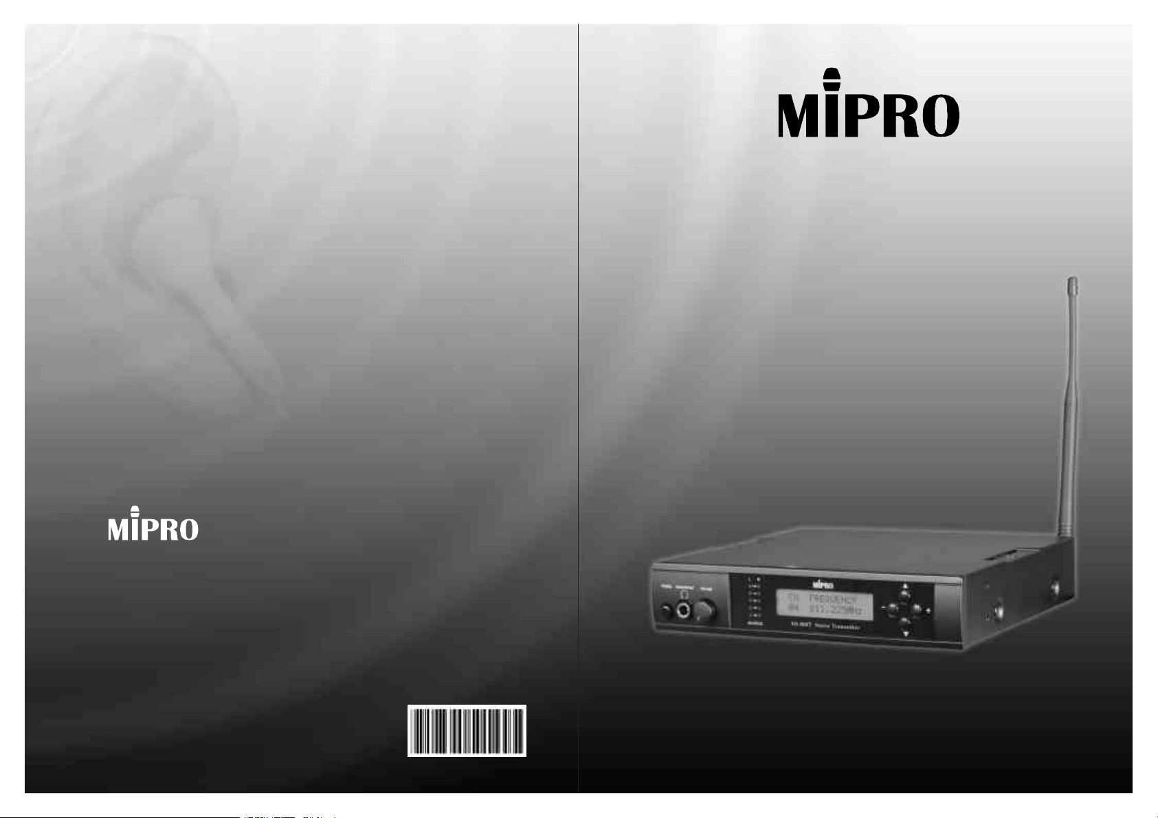
MI-808TStereoTransmitter
UserGuide
E-mail:@mipro.com.twmipro
2CE180
Page 2

Index
StereoTransmitter
1.Preface:
1.Preface:
2.FeaturesofMI-808T:
3.Glossary:
4.OperatingMI-808R:
5.ImportantNotes:
1
2
3
4-8
8
ThankyouforchoosingMIPRO'sfinestminiaturestereotransmitter.
Thissystemisengineeredtosatisfyallworkrequirementsinproaudio
applications,suchasmusicians,performers,anddirectors.
Togetthemostoutofyoursystem,pleasereadtheapplicablesection
thoroughlyinthisguidebeforeyouattempttousethesystem.
CharacteristicofMI-808T:
MI-808Tisawirelessmonitoringsystemdesignedspeciallyforpeoplein
stageperformanceandbroadcasting.Mainpurposeofthissystemistoallow
peopletolistentotheiraudiosourceseasilyinsteadofviacomplicatedaudio
cablesormonitoringspeakers.Inaddition,MI-808Tcanserveasconference
PAsystemormulti-lingualtranslator.Toincreaseaudioquality,S/Nratio,and
dynamicrange,MIPROadopts"DynamicSignalProcessingTechnology"to
limitnoiseleveltoitsminimal.
YourPackageContainstheFollowingAccessories﹕
Switchingpowersupply
Antenna1×
UserGuide
0
1
Page 3
StereoTransmitter
StereoTransmitter
2.FeaturesofMI-808T:
MI-808TisanUHFstereotransmittorwithpreset16non-interferece
frequenciesineach24MHz.Itisthebestchoiceforprofessionalstage,
furthermore,itiscompatiblewithMIPROWirelessMicrophoneSystemwithits
characteristicofhighspuriousemission.
Features:
1.LCDdisplaypanel
2.InternationalEIAstandard1/2-rackunit
3.InputSocketforBalancedandunbalanced.
4.Selectableforstereoormonofunction.
5.AdoptUHFPLLsynthesizeddesignwhereeachfrequencybandcovers
24MHzbandwithand16non-interferencechannels.
6.Featureshigh-passS/NRatioover90dB.
7.Built-inlimitingcircuittoavoidsounddistortionfromhugeinput.
8.FeaturesmonitoringoutputsocketofHeadphone.
ImportantNote:
MusttouseMIPROdesignedminireceivertomatchMI-808Ttransmitter.
3.Glossary:
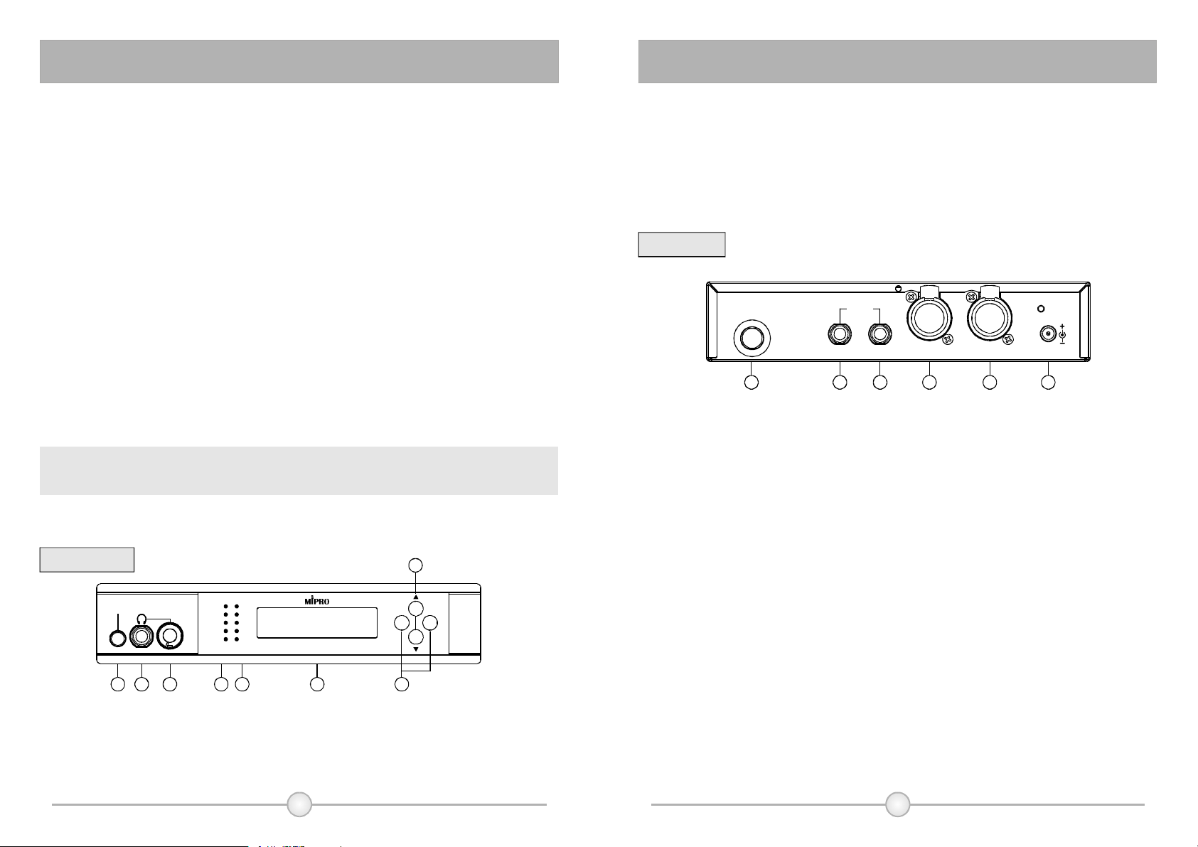
(4)LeftLevelIndicator,includinglimitorindicator.
(5)RightLevelIndicator,includinglimitorindicator.
(6)LCDDisplayPanel:Displaythedetailsofsettingandspecification.
(7)ModificationFunctionKey:Modifysettingfunction.
(8)FunctionSelectingKey:Selectsettingfunction.
RearPanel:
ANTENNA
9 10 11 12 13 14
(9)TransmittionSignalOutputConnector:InstalltransmittionAntennas.
(10)LeftUnbalancedOutputLevelSocket.
(11)RightUnbalancedOutputLevelSocket.
(12)LeftInputLevelSocket:Mixedusedforbalancedandunbalancedinput.
(13)RightInputLevelSocket:Mixedusedforbalancedandunblancedinput.
(14)DCPowerInputSocket:Toconnect15VDCpowerinputSocket.Connectthe
centerpoleofthejacktopositivevoltage.
LOOPOUT
AFIN(L) AFIN(R)
DCIN(15~18V)L R
(2)(fig.
FrontPanel:
POWER HEADPHONE VOLUME
SOURCE
4
L R
LIM
-12
-20
-30
-40
FREQUENCY
CH
04
MI-808TStereoTransmitter
MHz
5
22.181
6
8
-
+
75321
(1)(fig.
(1)PowerSwitch:Toturnonandoffthepowersupplyforthesystem.
(2)HeadphoneOutputSocket:AllowlinkingwithstereoHeadphonetomonitoroutput
signal.
(3)VolumeControl:AdjustthevolumeofstereoHeadphonebycounterclockwise
direction.
2
3
Page 4
StereoTransmitter
StereoTransmitter
4.OperatingMI-808T:
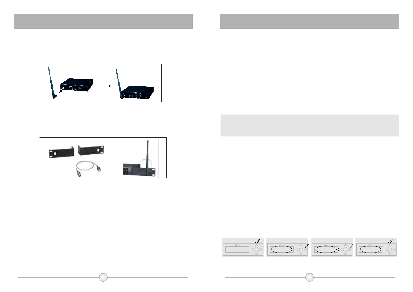
1.InstallationofAntenna
Installcoaxialcableonthetransmitterwillreachthebesttransmissioneffectsbut
itmustnoticefrequencyconsistencyforbothantennaandtransmitter.
2.InstallationofFrontAntenna
SelectFB-71Rackmountkit,useoneendtoconnectwithoutputsocketof
transmissionsignalandtheotherendconnectwithtransmissionantennas.The
transmissioneffectwillenhanceifinstallantennasinfrontofthepanel.
3.InstallationofPowerSupply
ConnectoutputendofDC12V~15V/1ApowersupplywithinputsocketofAC
poweroftransmitter.ToavoidthefalloffofDCplugaccidentally,gettingthrough
linkingcablefromfixholeandthenfastenit.
4.Turnonthetransmitter
Whenturnonthepowerswitch,thegreenLCDdisplaywillbebrightandshowall
informationonit.TransmitterwilloutputtransmissionsignalifPLLcircuitislocked.
5.Line-inLevelinput
ItcanselectstereoormonoLin-ininput,thesignalwillinputfromAFINofright
side.ItcanselectXLR-3balancedinputjackor6.3mmunbalancedinputjack.
φ
Becauseofcompoundsocket,itisavailableforbothtypeofjacks.
Cause:
ThestrengthlevelofsignalinputisLINELEVEL.Itmustmagnifythesignal
beforeinputifMICPHONELEVELinputisnecessary,otherwisesensitivityis
insufficient.Suggesttoconnectwithmonitoroutputjackofmixer.
6.SetupappropriateLINELEVEL
ThestrengthofLINELEVELinputwillshowontwobarofLINELEVELlistofleft
side.Adjustthestrengthofoutputappropriatelytolightupthreelamps.Themaximum
ofdisplayofLINELEVELwouldnotexceedfourlights.Wheninputstrengthexceeds
thestrengthoffourlights,theredlightwilllightup;andtheninputsignalshouldbe
limitedandmodulationshouldnotincrease.Therefore,adjustappropriateinput
strengthtoobtainthebestdynamicrangeandS/Nratioandavoidsignaldistrotion.
7.Howtosetuptransmissionfrequency:
a)Pressup/downkey,thenLCDdisplaywouldshowpresetfrequency.
b)Pressleft/rightkeyandthenLCDdisplaywillstartblinking.
c)Pressleft/rightkeytoselectdesiredfrequency.
d)Pressup/downkeytokeeptheLCDdisplayfixedandthentheselectedfrequency
isupdatedandsaved.
a)
FREQUENCY
CH
MHz
0
5
2 2.181
4
MI-808TStereoTransmitter MI-808TStereoTransmitter MI-808TStereoTransmitter MI-808TStereoTransmitter
4
b)
Displaystartsblinking ChangeFrequency SaveFrequencySelecttothedisplayoffrequency
FREQUENCY FREQUENCY FREQUENCY
CH CH CH
MHz MHz MHz
0 0 0
5 0 0
2 8 82 0 0. . .1 4 48 8 81 1 1
4 5 5
c) d)
5
Page 5
StereoTransmitter
StereoTransmitter
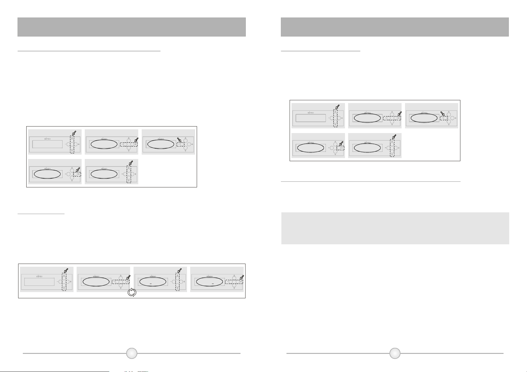
8.TheoperatingtoselectStereoandMonosound
a)Pressup/downkeytodisplaySTEREO/MONOON/OFF.
b)Pressleft/rightkey,thenthedisplaystartblinking.
c)PressleftkeyandtheSTEREOwilldisplaythepositionofON.Itindicatesthe
selectingofStereotransmission.
d)PressrightkeyandMONOwilldisplaythepositionofON.Itindicatesthe
selectionofMonotransmission.
e)Pressupordownkeythenthedisplaystopsblinking.Atthisstage,theselecting
issaved.
a)
MONO MONO
STEREO STEREO STEREO
ON ON ONOFF OFF OFF
MI-808TStereoTransmitter MI-808TStereoTransmitter MI-808TStereoTransmitter
d)
SelectMonoSound
STEREO
MONO
ON OFF
MI-808TStereoTransmitter
b)
e)
Displaystartsblinking SelecttoStereoSoundSelecttoModeDisplay
SaveMode
STEREO
MONO
ON OFF
MI-808TStereoTransmitter
c)
MONO
9.SettingName
a)Pressup/downfunctionkeytodisplayNAMEonLCDdisplay.
b)Pressleft/rightfunctionkeythenthedisplaywillstartblinking.
c)Pressup/downfunctionkeytosetupalphabetornumerals.
d)Pressleft/rightfunctionkeytoskiptosettingofnextcharacter.Thenfinishthe
settingof6charactersbyduplicateoperation.
10.SettingofLockFunction
a)Pressup/downkeytodisplayLockFunction.
b)Pressleftkey,displaywillshowLOCKON,allsettingislocked.Settingcan'tbe
changedbeforeremovingLockfunction.
c)Pressrightkey,displaywillshowLOCKOFF,Lockfunctionisremovableand
allowtochangeeachsetting.
a)
LOCK LOCK LOCK
OFF OFF ON
MI-808TStereoTransmitter
d)
RemoveLockFunction
LOCK LOCK
OFF OFF
MI-808TStereoTransmitter MI-808TStereoTransmitter
b)
Displaystartsblinking LockFunctionSelecttoLockDisplay
MI-808TStereoTransmitter MI-808TStereoTransmitter
e)
SaveMode
c)
11.HowtoMonitorSoundSignalandConnectwithHeadphone
PlugstereoheadphoneintoHeadphoneoutputsocket(2)andusevolumecontrol
toadjustthevolumeappropriately.Itmustadoptstereoconnectorof6.3mm.φ
Caution:
Toprotectyourhearing,adjustthevolueappropriately.Theoutputofheadphone
willoccurwhenvolumeistooloud.
Thesystemwillsaveandupdatecurrentsettingautomaticallyoncepressnoneof
thebottonin5secondswhenblinking.
a)
NAME NAME NAME NAME
ABCDEF ABCDEF -MCDEF -MIPRO
MI-808TStereoTransmitter MI-808TStereoTransmitter MI-808TStereoTransmitter MI-808TStereoTransmitter
b)
Thedisplayisblinking Changethename SelectnextcharacterSelecttothedisplayofNAME
b)c)c)
d)
6 7
Page 6
StereoTransmitter
StereoTransmitter
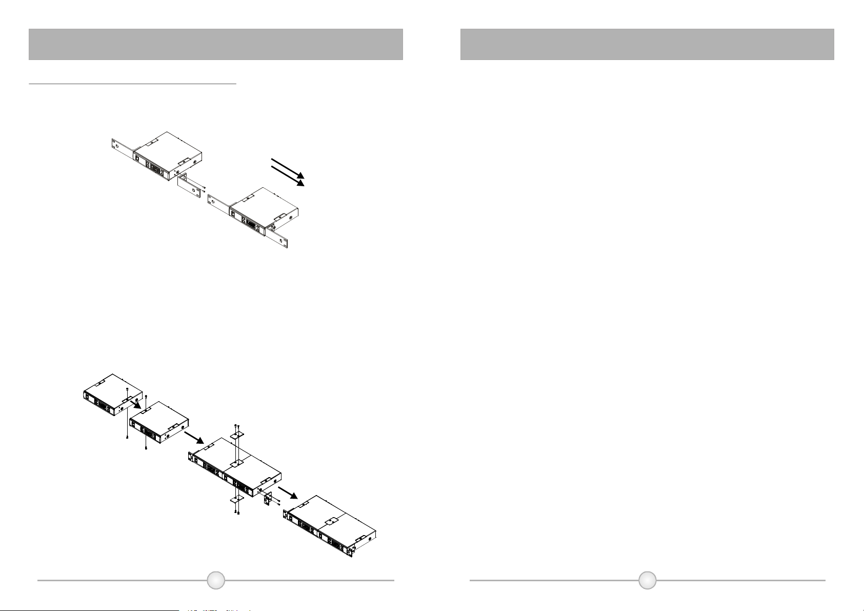
13.RackInstallationof2UnitsofMI-808T
A)Singlehalf-racktransmitter
① ScrewthefixedrackmountearonLeftandRightsides.Pleaseseebelow
illustrationforcorrectassembly.(Fig.5)
B)Dualhalf-racktransmitters
①
Removethescrewsoftopandbottomofthetwotransmitters
counterclockwise.
②
Positiontheconnectplatesbetweenthetopandbottomofthetwo
transmittersandtighten.
③
Afterjoiningthetwotransmitterstogether,screwtheoptionalaccessoryrack
mountears(FB-72)onleftandrightsides.(Fig.6)
(5)(fig.
5.ImportantNotes:
1.Don'tusesamefrequencybandforbothmonitorandwirelessmicrophone
systemwhentheyworksimultaneously.
2.Itmustuse50coaxialcabletoconnectthetransmissionsignalto
exteralantennas.Avoidtouselongcableexceeding5meterswhenuse
RG-58or3Dcables.
3.Itisbettertomaintainnon-barriersightdistancebetweentransmission
antennasandreceiver.Thisdistancewillshortenoncetherearetoo
manybarrierstoabsorbelectricwaveandobjects.
4.WhenusingDCpowersupply,pleasebeawareoftheoperatingvoltage.
Pleasemakesureminimumof12voltscanbeobtainedforfunction
properly.However,thepowersupplyshouldnotexceeditsmaximum
capacityof18volts.Whenthesupplyvoltageistoohigh,thesystemwill
suffersevereinternaldamange.Itispreferredthepowersourceisfrom
aregulatedpowerwiththeminimumcurrentof500mA.
Ω
Notice:
Thechangesormodificationsnotexpresslyapproved
bythepartyresponsibleforcompliancecouldvoidthe
user'sauthoritytooperatetheequipment.
IMPORTANTNOTE:
TocomplywiththeFCCRFexposurecompliance
requirements,nochangetotheantennaorthedeviceis
permitted.Anychangetotheantennaorthedevicecould
resultinthedeviceexceedingtheRFexposure
requirementsandvoiduser'sauthoritytooperatethe
device.
(fig.6)
8 9
Page 7

NOTE﹕NOTE﹕
1110
 Loading...