

Page 1
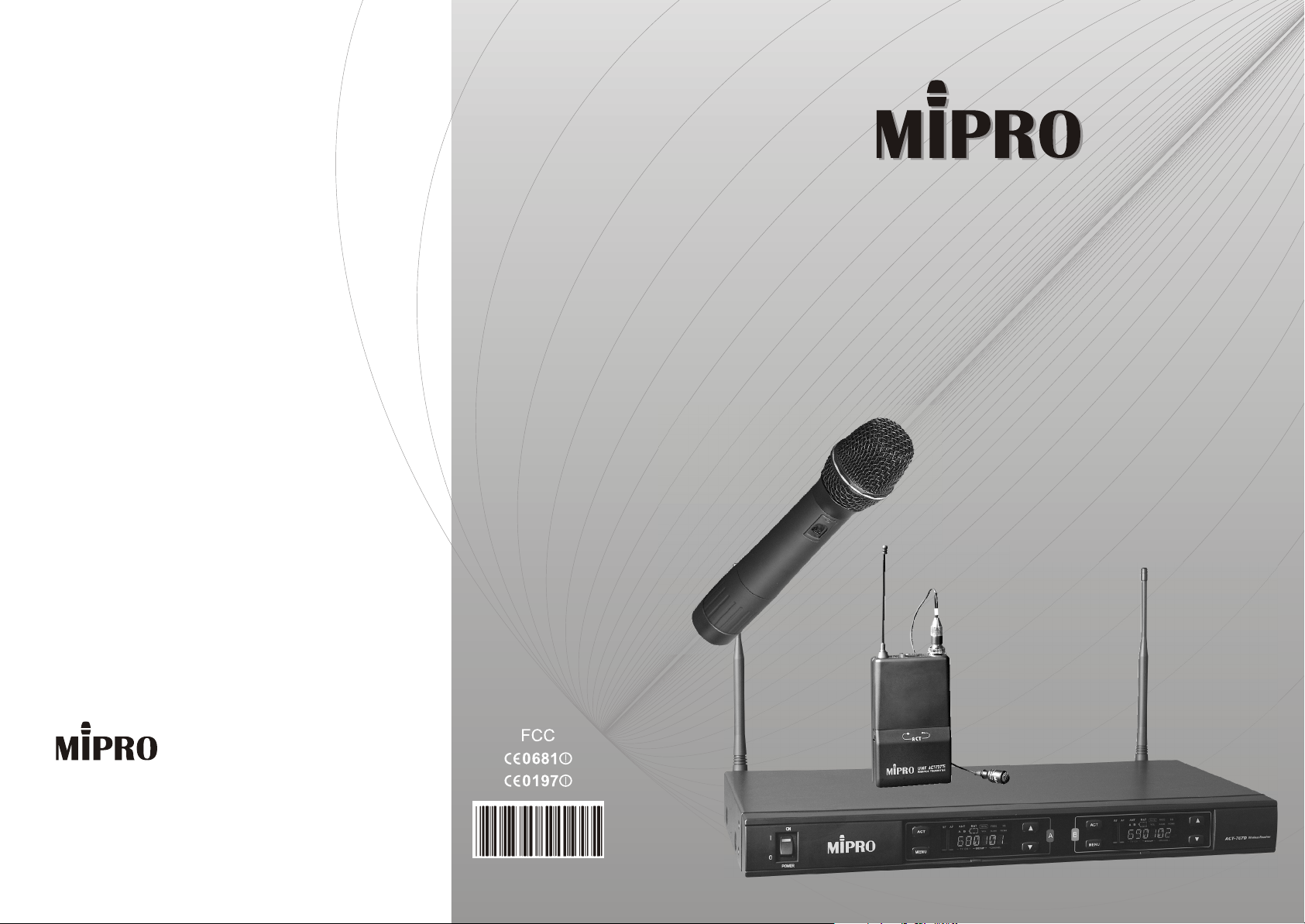
ACT-Series Dual Channel Wireless Receiver
ACT-Series Dual Channel Wireless Receiver
Instruction Manual
Z 1- rack Frame
Z ACT-function
Z Color LCD Panel
Z Dual 100 Preset Channels
Electronics Co., Ltd.
Head office: 814, Pei-Kang Road, Chiayi, 600, Taiwan.
Taipei office: 5, Lane 118, Sung-teh Road, 100, Taipei, Taiwan.
Web-http: //www.mipro.com.tw
E-mail: [email protected]
2CE128
Page 2
CONTENTS
ACT DUAL CHANNEL WIRELESS RECEIVER
ACT DUAL CHANNEL WIRELESS RECEIVER
1. INTRODUCTION
2. PARTS NAME AND FUNCTIONS
3. INSTALLATION OF THE RECEIVER
4. RECEIVER OPERATING PROCEDURES
5. CAUTIONS
6. OPERATION OF RECEIVER WITH LCD DISPLAY PANEL
HANDHELD WIRELESS MICROPHONE
1. PARTS NAME AND FUNCTIONS
2. BATTERY INSERTION
3. OPERATING INSTRUCTIONS
4. CAUTIONS
BELT PACK TRANSMITTER
1
2-3
4-5
6
6
7-13
14
15
15
15
1. INTRODUCTION
Thanks for choosing the most advanced dual channel wireless receiver
system from MIPRO.
Please read this manual thoroughly for correct operating and optimal
performance.
ACT-707D is an international EIA standard, 1-rack, true diversity metal
receiver. It features the world's first ACT-function, color LCD panel displaying
multiple statuses. It allows rapid change of channels, offers non-interfering
channel selection and eliminates spurious interference. Other unique features
include a built-in switch-mode power supply, an antenna divider system and
independent or mixed outputs. It's 1-rack, dual-channel design saves space
and reduces installation time. Another great value system! The ideal choice for
dual-channel receives in one rack space!
Included Accessories
Antenna 2 Instruction Manual 1
Power Cable 1 Rack-mount Brackets 1-pair
Audio Output Cable 1
1. PARTS NAME AND FUNCTIONS
2. OPERATING INSTRUCTIONS
3. AF 4-PIN INPUT CONNECTION METHODS
4. BATTERY INSERTION
5. CAUTIONS
16-17
17
18
19
19
0
1
Page 3
ACT DUAL CHANNEL WIRELESS RECEIVER ACT DUAL CHANNEL WIRELESS RECEIVER
2. PARTS NAME AND FUNCTIONS
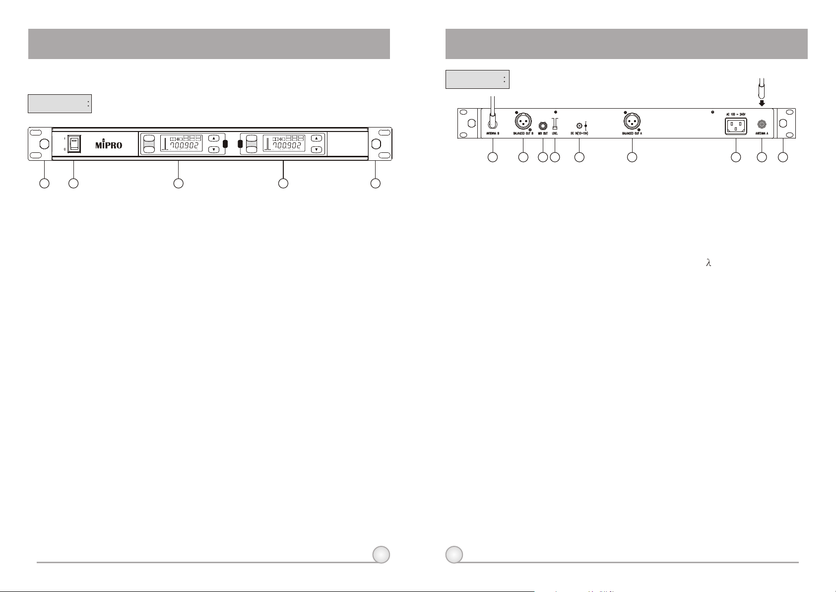
Front Panel
ON
POWER
2 3 4
1 5
(1) Front Antenna A Input Connector : Allows an optional rear-to-front
Antenna kit for front antenna placement.
(2) Power Switch & Indicator: When switch is turned on, red indicator
illuminates to denote normal power status.
(3) Receiver Panel A : Color LCD Panel A.
(4) Receiver Panel B : Color LCD Panel B.
(5) Front Antenna B Input Connector : Allows an optional rear-to-front
Antenna kit for front antenna placement.
RF AF
ANT
BAT
FREQ SQ
ACT
MENU
G/CH
A
B
VOL
REMO
NAME
GROUP
TV CH
CHANNEL
A B
MHz
RF AF
ANT
BAT
FREQ SQ
ACT
MENU
G/CH
A
B
VOL
REMO
NAME
MHz
GROUP
TV CH
CHANNEL
ACT-707D
Wireless Receiver
(Fig.1)
Rear Panel
MIC LINE
6
7
8 9 10 12
11
13
14
(Fig.2)
(6) Rear Antenna B input Connector: B Antenna connector can be
installed with antenna directly and provides power for antenna booster..
(7)(11) Balanced Audio Output Jack: With Cannon / XLR type connector
provides balanced audio output signal from this jack to the amplifier.
(8) Unbalanced Audio Mixed Output Jack : With 1/ 4 Phone Jack
provides the mixed unbalanced audio output signal from this jack to the
amplifier.
(9) Unbalanced Level Switch: "MIC" selection is for "Microphone-level"
output. "LINE" selection is for "Line-out" level output.
(10) DC 12V Input Jack: To connect 12 VDC from the AC/DC adapter.
(12) AC Input Jack: To connect 85 ~ 265 Volts AC power.
(13) Rear Antenna A input Connector: A Antenna connector can be installed
with antenna directly and provides power for antenna booster.
(14) Rackmount Bracket: To install the receiver into an EIA 19-inch standard
rack case.
2
3
Page 4
ACT DUAL CHANNEL WIRELESS RECEIVER ACT DUAL CHANNEL WIRELESS RECEIVER
3. INSTALLATION OF THE RECEIVER
MIC LINE
(Fig.3)
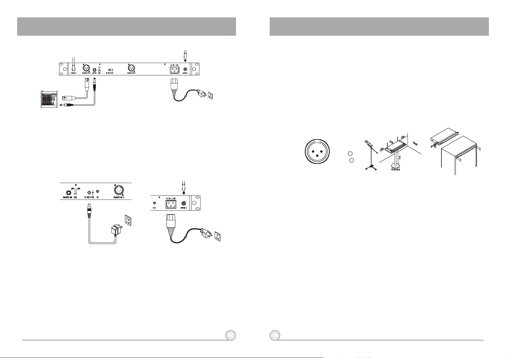
1. Install 2 separate antennas on the antenna sockets (6), (13) on the rear
panel. Illustrated in figure 3.
2. Power Output Connection:
(a) Connect the AC/DC adapter cable to DC 12V INPUT JACK (10), then plug the
adapter unit into an appropriate AC outlet with caution to the correct voltage
under both AC outlet and adapter marked, as shown in fig. 4.
(b) With the appropriate AC power cable connects from AC Input Jack (12) to an
AC outlet under the marked voltage 85~265 V, as shown in Fig. 5.
(b) Unbalanced Output: Using audio output cable attached with "PHONE
PLUG" type, connect one end from the unbalanced output jack (8) of the
receiver, and the other end to the "LINE-IN" input jack of the amplifier, as
shown in Fig. 3.
(c) Balanced Output: Using audio output cables attached with "XLR" or
"Cannon" type, connect one end from the balanced output jacks (7) of the
receiver, and the other end to the "MIC IN" input jack of the mixer or
amplifier, as shown in Fig. 3. (The characteristic of the 3-pin connector is
as shown in Fig. 6
(d) Guitar Output: Using audio output cable attached with "PHONE PLUG" type,
plug one end from the unbalanced output jack of a receiver, and the other
end to the input jack of a guitar amplifier. Switch the Level Switch (9) to
"LINE" position.
1: GND
21
3
(Fig.6)
2: HOT
3: COLD
+ +
- -
(Fig.8)(Fig.7)
4. To ensure best reception possible, receiver must be installed at least one
meter above ground. In addition, the distance between transmitter and
receiver must be more than one meter and away from noise. (Shows in
figure 7)
5. On the front panel of the receiver, 4 openings are pre-drilled for instant
installation on the standard 19-inch rack case. (Shows in figure 8)
(Fig.4)
(Fig.5)
3. Audio Output Connection:
(a) Unbalanced Level Switch (9) Setting Position: When inputs the unbalanced
output of a receiver into "AUX-IN" input jack of a mixer or amplifier or "Electric
Guitar", switch the Level Switch (9) to the right "LINE" position. Low
sensitivity may occur if switch to the wrong position. When input the
unbalanced output of a receiver into the "MIC-IN" input jack of a mixer or
amplifier; switch the Level Switch (9) to the left "MIC" position. Over load
distortion may occur if switch to the wrong position. When using electric guitar,
don't use "MIC" position as it may have generated insufficient level.
4
5
Page 5
ACT DUAL CHANNEL WIRELESS RECEIVER ACT DUAL CHANNEL WIRELESS RECEIVER
4. RECEIVER OPERATING PROCEDURES
1. Turn volume controls of the mixer in use to a minimum setting before turn
on the microphones or transmitters. After switches on the receiver, the
power switch red indicator illuminates to denote normal power status.
2. Under normal circumstances, the RF indicator lights up when a
microphone or transmitter is turned on near the receiver to indicate the
receiver is ready for normal operation. Once sounds to the microphone
and the AF indicators will glow according to the strength of sound level.
If no LED glows or no sound outputs, the system is not function properly,
thus it must be checked
3. The microphone output level needs to be adjusted at the amplifier or
mixer. No need to adjust at the receiver itself.
5. CAUTIONS
1. When using DC power supply, please be aware of the operating voltage.
First of all, please make sure minimum of 12 volts can be obtained for
function properly. However, the power supply should not exceed its
maximum capacity of 15 volts. When the supply voltage is more than 15
volts, the system will suffer severe internal damage. It is preferred the
power source is from a regulated power with the minimum current of 1 A.
2. Use only MIPRO standard antenna to ensure the sensitivity of the
receiver.
3. Antenna socket has 8-volts DC power supply; please do not short the
circuit of this part.
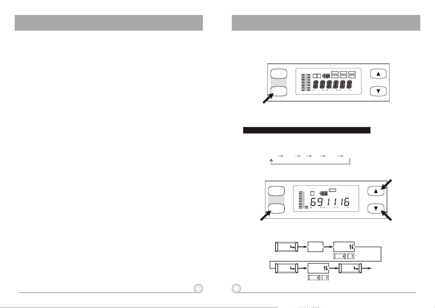
6. Operation of Receiver with LCD Display Panel
1. Full Display of LCD Screen and Locations of buttons
ACT
MENU
RFRF AFAF
2. Designations of buttons and Functions
MENU: Enable user to select from one function to the other
"MENU" button allows user to select among 6 options (in the sequence
showing below) that each is surrounded in a square frame and shown on the
upper half of LCD display. Detail functions and operations are as follows.
G/CH FREQ SQ VOL NAME REMO
(1) G/CH: Indicates or setups the receiver GROUP and CHANNEL.
ACT
MENU
RFRF AFAF
AA
TV CHTV CH
AA
TV CHTV CH
BB
BATBATANTANT
BB
BATBATANTANT
GROUPGROUP
GROUPGROUP
G/CHG/CH
VOLVOL
G/CHG/CH
VOLVOL
FREQFREQ SQSQ
NAMENAME
CHANNELCHANNEL
FREQFREQ SQSQ
NAMENAME
CHANNELCHANNEL
REMOREMO
MHzMHz
REMOREMO
A. Operating Procedures.
MENU
MENU
6
7
G/CH
CHANNEL
DOWN UP
GROUP
DOWN UP
MENU
Save
EXIT
Page 6
ACT DUAL CHANNEL WIRELESS RECEIVER ACT DUAL CHANNEL WIRELESS RECEIVER
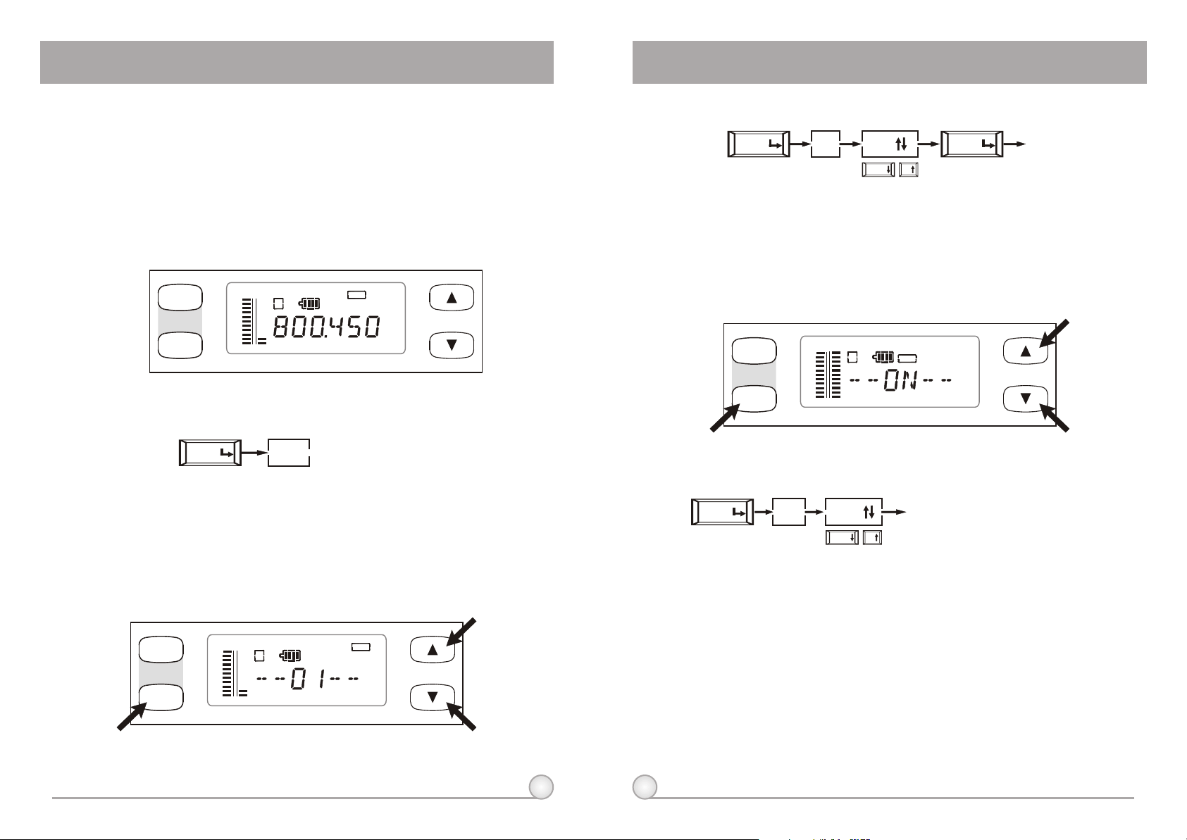
B. How to Operate?
a. In the lower row of LCD display, TV CHANNEL, GROUP, and CHANNEL are
separately shown in dual-digit numbers (from left to right).
b. Push "UP" or "DOWN" button once and the number above "GROUP" will start
blinking. Push "UP" or "DOWN" button now will permit user to change to another
pre-programmed group. Push "MENU" button to confirm the modification and group
number will stop blinking.
(2) FREQ: Indicates the frequency that is currently in use.
ACT
MENU
RFRF AFAF
BATBATANTANT
AA
BB
G/CHG/CH
VOLVOL
FREQFREQ SQSQ
NAMENAME
REMOREMO
MHzMHz
A. Operating Procedures.
MENU
FREQ
B. How to Operate?
a. After push "MENU" button and select the "FREQ" frame, it will show the frequency
that is set under the GROUP and CHANNEL that one had selected previously.
b. This function cannot be used for frequency alternation.
(3) SQ: Indicates or setups the Squelch level.
ACT
MENU
RFRF AFAF
BATBATANTANT
AA
BB
G/CHG/CH
VOL VOL
FREQFREQ SQSQ
REMOREMO
NAMENAME
A. Operating Procedures.
MENU
SQ
01
DOWN UP
MENU
save
EXIT
B. How to Operate?
a. User can set the squelch level within the range of 01-99.
b. To set the squelch level, simply by pushing the "UP" or "DOWN" button and confirm
the modification by pushing "MENU" button.
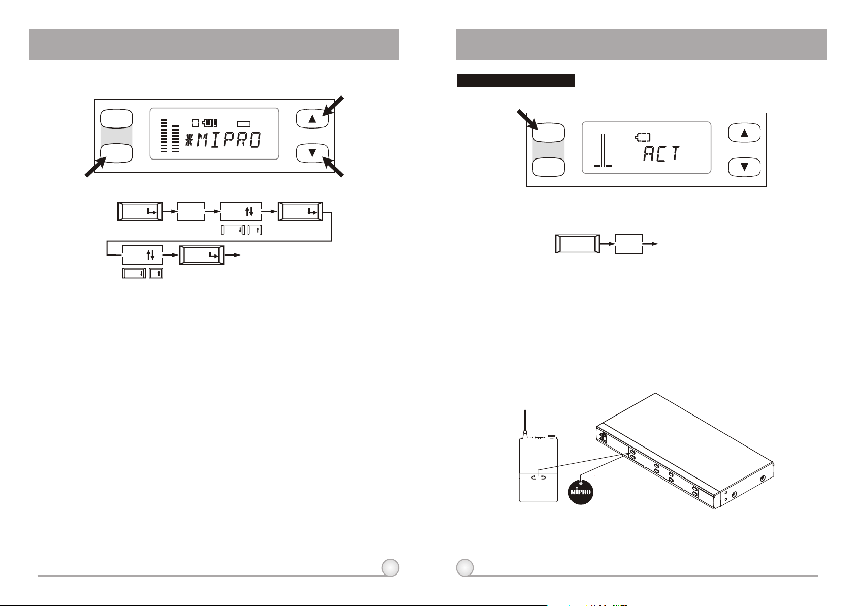
(4) VOL: Indicates Volume Level is at On or Mute position.
ACT
MENU
RFRF AFAF
BATBATANTANT
A A
B B
G/CHG/CH
VOLVOL
FREQFREQ SQSQ
NAMENAME
REMOREMO
Switching From Audible To Mute
A. Operating Procedures.
MENU
VOL
B. How to Operate?
Push "UP" or "DOWN" Button allows one to switch volume to "ON" or "Mute" status.
C. CAUTIONS :
AF bar and Ant. A, B of LCD panel will not displayed when the receiver module is
at Mute status. To ascertain if receiver is at Mute status, press Menu key, select
Volume. If LCD indicates "Mute" it is a Mute status. If LCD indicates "On" audio is
operating normally.
MUTE
DOWN UP
EXIT
8 9
Page 7
ACT DUAL CHANNEL WIRELESS RECEIVER ACT DUAL CHANNEL WIRELESS RECEIVER
(5) NAME: Indicates or setups the name of current channel user.
ACT
MENU
RFRF AFAF
BATBATANTANT
A A
B B
G/CHG/CH
VOLVOL
FREQFREQ SQSQ
NAMENAME
REMOREMO
A. Operating Procedures.
MENU
A
DOWN UP
NAME
MENU
save
A
DOWN UP
EXIT
MENU
NEXT
B. How to Operate?
a. Maximum 6 characters are allowed (Select from capitalized English letter, numbers,
+ - x /, and space).
b. Push "UP" or "DOWN" button into setup mode and the character on the far left will
start blinking. (There will be no blinking if there is no character in the specific space).
c. Push "UP" or "DOWN" button to select desired character and confirm by pushing the
"MENU" button. Once confirmed, the next character will start blinking and ready for
setup.
d. Repeat step c until ALL 6 characters are set.
Operation of ACT Feature:
ACT
MENU
A. Operating Procedures.
B. How to Operate?
a. At LCD panel displays "Group" and "Channel" mode keystroke "ACT"
button . ACT mode is activated when "ACT" word appears on the
LCD panel.
b. Position the "ACT" marking of the transmitter about 30cm (12-inch)
towards the "ACT" button on the receiver. (see below figure)
c. ACT function will release automatically once the transmitter channel is
locked on. Simultaneously, "Group" and "Channel" mode will be
back showing on the LCD panel.
ACT
RFRF AFAF
ANTANT
A A
ACT
BATBAT
B B
G/CHG/CH
VOLVOL
FREQFREQ SQSQ
NAMENAME
REMOREMO
EXIT
10
ACT
11
Page 8
ACT DUAL CHANNEL WIRELESS RECEIVER ACT DUAL CHANNEL WIRELESS RECEIVER
NOTE NOTE
12
13
 Loading...