

Page 1
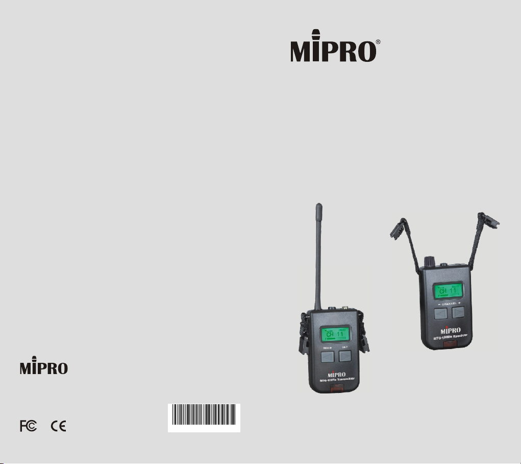
User Guide
2 CE4 3 5A
MTG-100
Digital Wireless Tour Guide System
MIPRO Electronics Co., Ltd.
Headquarters: 814 Pei-Kang Road, Chiayi, 60096, Taiwan.
Web: www.mipro.com.tw
E-mail: [email protected]
Design and specifications are subject to change without prior notice
MTG-100Ra
MTG-100Ta
AS111101
100% Made In Taiwan
Page 2
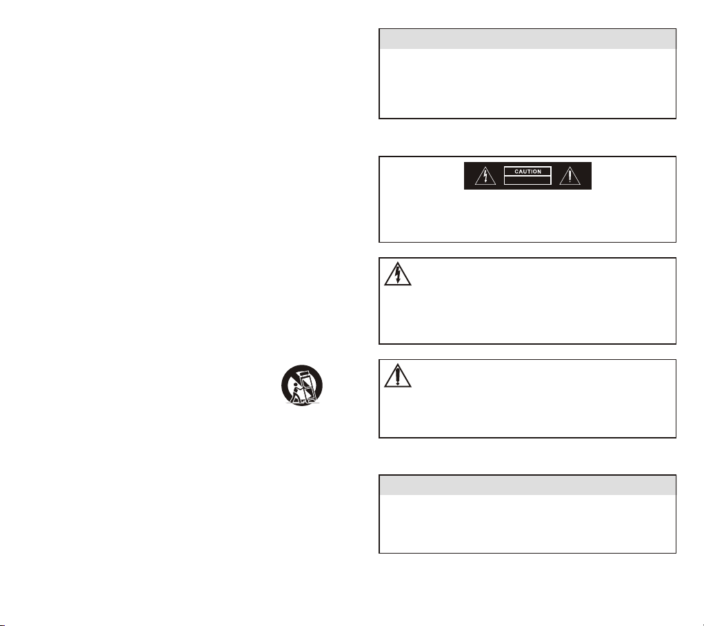
IMPORTANT SAFETY INSTRUCTIONS
1. Read these instructions.
2. Keep these instructions.
3. Heed all warnings.
4. Follow all instructions.
5. Do not use the apparatus near water.
6. Clean only with dry cloth.
7. Do not block any ventilation openings. Install in accordance
with the manufacturer's instructions.
8. Do not install near any heat sources such as radiators, heat
registers, stoves, or other apparatus(including amplifiers)
that produce heat.
9. Do not defeat the safety purpose of the polarized or
grounding-type plug. A polarized plug has two blades with
one wider than the other. A grounding-type plug has two
blades and a third grounding prong. The wide blade or the
third prong is provided for your safety. If the provided plug
does not fit into your outlet, consult an electrician for
replacement of the obsolete outlet.
10. Protect the power cord from being walked on or pinched
particularly at plugs, convenience receptacles, and the point
where they exit from the apparatus.
11. Only use attachments/accessories specified by the
manufacturer.
12. Use only with a cart, stand, tripod, bracket or table
specified by the manufacturer, or sold with the
apparatus. When a cart is used, use caution when
moving the cart/apparatus combination to avoid
injury from tip-over.
13. Unplug this apparatus during lighting storms or when
unused for long periods of time.
14. Refer all servicing to qualified service personnel. Servicing
is required when the apparatus has been damaged in any
way, such as power-supply cord or plug is damaged, liquid
has been spilled or objects have fallen into the apparatus,
the apparatus has been exposed to rain or moisture, does
not operate normally, or has been dropped.
15. When the main plug or appliance coupler used as the
disconnect device, it shall remain readily operable.
16. Please keep the unit in a good ventilation environment.
17. The appliance coupler is used as the disconnect device, the
disconnect device shall remain readily operable.
WARNING
To reduce the risk of fire or electric shock, do not expose
this apparatus to rain or moisture. The apparatus shall
not be exposed to dripping or splashing and that no
objects filled with liquids, such as vases, shall be placed
on the apparatus.
DO NOT OPEN
RISK OF ELECTRIC SHOCK
CAUTION: To reduce the risk of electric shock, do not
remove any cover. No user-serviceable parts inside. Refer
servicing to qualified service personnel only.
The lightning flash with arrowhead symbol within
the equilateral triangle is intended to alert the use
to the presence of un-insulated "dangerous
voltage" within the product's enclosure that may
be of sufficient magnitude to constitute a risk of
electric shock.
The exclamation point within the equilateral
triangle is intended to alert the user to the
presence of important operation and maintenance
(servicing) instructions in the literature
accompanying this appliance.
CAUTION
To prevent electric shock, do not use this polarized plug
with an extension cord, receptacle or other outlet unless
the blades can be fully inserted to prevent blade
exposure.
Page 3

Federal Communication Commission
Interference Statement
This equipment has been tested and found to comply with
the limits for a Class B digital device, pursuant to Part 15
of the FCC Rules. These limits are designed to provide
reasonable protection against harmful interference in a
residential installation.
This equipment generates, uses and can radiate radio
frequency energy and, if not installed and used in
accordance with the instructions, may cause harmful
interference to radio communications. However, there is no
guarantee that interference will not occur in a particular
installation. If this equipment does cause harmful
interference to radio or television reception, which can be
determined by turning the equipment off and on, the user
is encouraged to try to correct the interference by one of
the following measures:
!
Reorient or relocate the receiving antenna.
!
Increase the separation between the equipment and
receiver.
!
Connect the equipment into an outlet on a circuit
different from that to which the receiver is connected.
!
Consult the dealer or an experienced radio/TV technician
for help.
FCC Caution: To assure continued compliance, any
changes or modifications not expressly approved by the
party responsible for compliance could void the user's
authority to operate this equipment. (Example - use only
shielded interface cables when connecting to computer or
peripheral devices).
IC
This device complies with Industry Canada licence-exempt
RSS-210 standard.
"Operation is subject to the following two conditions:
(1) this device may not cause interference, and
(2) this device must accept any interference, including
interference that may cause undesired operation of the
device."
Disposal
2005 -08- 132005 -08- 13
Dispose of any unusable devices or batteries
responsibly and in accordance with any
applicable regulations.
Disposing of used batteries with domestic
waste is to be avoided!
Batteries / NiCad cells often contain heavy
metals such as cadmium(Cd), mercury(Hg) and
lead(Pb) that makes them unsuitable for
disposal with domestic waste. You may return
spent batteries/ accumulators free of charge to
recycling centres or anywhere else
batteries/accumulators are sold.
By doing so, you contribute to the conservation
of our environment!
This device complies with part 15 of the FCC rules.
Operation is subject to the following two conditions
(1) This device may not cause harmful interference and
(2) This device must accept any interference received,
including interference that may cause undesired operation.
Page 4

Contents
Digital Wireless T our Guide S ystem
Product Overview
1
2 Key Features
MTG-100Ra
3
Receiver Controls and Indicators
MTG-100Ta
4
Controls and Indicators
5
Transmitter
LCD Screen
5 Setting Up Receiver
8 Setting Up Transmitter
14 Battery Removal and Installation
15 Wearing Neck Lanyards
15 MTG-100Ta Transmitter Audio Input
16 MTG-100Ra Receiver Audio Input
17 Optional Microphone Accessories for
MTG-100Ta Transmitters
18 Optional Earphone Accessories for
MTG-100Ra Receivers
Product Overview
MTG-100 is an innovative digital wireless tour guide
system. It is ultra compact, lightweight and easy to
use. Digital design provides crystal-clear audio
quality, secured and reliable transmission and
insensitive to interference attributes that are
unmatched by the deficiency of simple analog
design systems.
It operates in the license-free ISM band. ISM band
requires no user licensing; thus, no worries about
changing groups and channels when operating in
multiple countries.
This system comprises of durable MTG-100Ra
portable receiver and MTG-100Ta portable
transmitter. Each band is preset with 16 switchable
frequencies and up to 4 compatible systems are
available ensuring several different tours or groups
can be operated at the same venue without
interfering with each other.
Both MTG-100Ra portable receiver and MTG-100Ta
portable transmitter required two 'AA' size
disposable alkaline batteries (recommended) for
small to large, indoor or outdoor applications for
guides, interpreters or presenters to communicate
effectively to a group of people, rejecting irritating
surrounding noise. MTG-100 is a ideal choice for
functional features and high performance wireless
tour guide system.
0
1
Page 5
Digital Wireless T our Guide S ystem Digital Wireless T our Guide S ystem
Key Features
!Operates on user license-free ISM bands.
!Industry's only true diversity design ensures
maximum reception quality and reduces signal
dropouts.
!Interference-free from Bluetooth, Wi-Fi and
2.4GHz wireless transmission.
!Encrypted digital technology enables secure audio
transmission, preventing unauthorized listening.
!Proprietary 16-bit audio compression technology
ensures crystal-clear sound quality.
!Miniaturized, lightweight receiver can be worn
comfortably around the neck with a lanyard or fit
inside any pocket.
!Easy to use, durable, reliable quality and
affordable price.
!Innovative automatic shut-off timer reduces
battery consumption.
!LCD displays battery level and other parameters.
!Channel lock - to avoid accidental changes.
!Net Weight:
MTG-100Ra: Approx. 50 g / 1.8 oz (excluding
battery) MTG100Ta: Approx. 50 g / 1.8 oz (excluding battery)
!Dimensions(W×H×D): 45 × 84 × 28mm /
1.8 × 3.3 × 1.1".
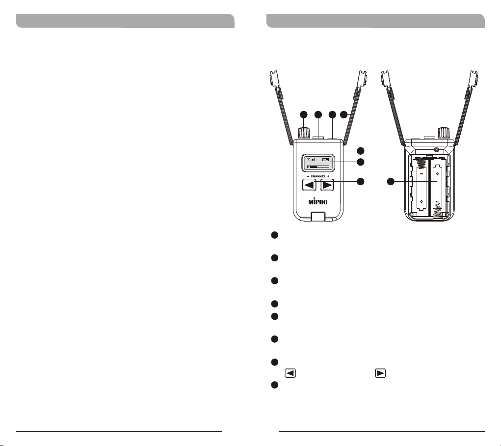
MTG-100Ra
Receiver Controls and Indicators
4
3
1
2
5
CH 1 2
MTG-100Ra Receiver
1
Volume Control: 1-20 levels volume
6
7 8
adjustment.
2
Power button: Press and hold for 2 seconds to
power on & off.
3
3.5mm Jack: Insert earphones or headphones
here.
4
Lanyards & Buckle: Detachable neck lanyards.
5
Housing: Holds internal circuitry and build-in
rechargeable battery.
6
LCD Display: Display channel, RF & audio
signals and battery status.
7
Channel Buttons: 16 factory preset channels.
, one channel down; one channel up.
8
Battery Compartment: Holds 2 'AA' batteries.
2
3
Page 6
Digital Wireless T our Guide S ystem Digital Wireless T our Guide S ystem
CH 1 2
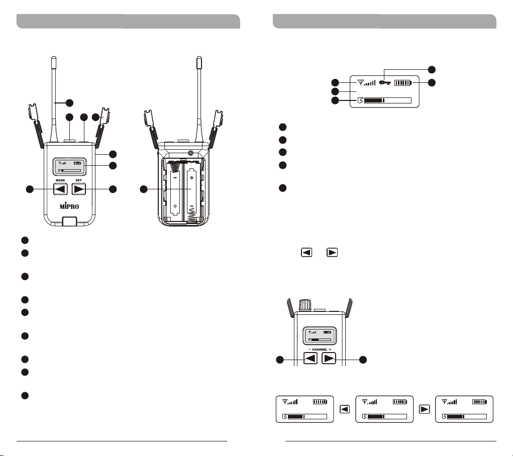
MTG-100Ta
Transmitter Controls and Indicators
9
12
10
11
13
868.125
MHz
15
MTG-100Ta Transmitter
9
Antenna: Transmitting antenna.
10
Power button: Press and hold for 2 seconds to
14
16
17
power on & off.
11
3.5mm Audio Input: Accepts Microphone-input
or Line-input.
12
Lanyards & Buckle: Detachable neck lanyards.
13
Housing: Holds internal circuitry and build-in
rechargeable battery.
14
LCD Display: Display channel, RF & audio
signals and battery status.
15
MODE button: To select functions.
16
SET button: To set and change parameter
values.
17
Battery Compartment: Holds 2 'AA' batteries.
LCD Screen
Displays current settings and indicators
22
18
19
20
18
Received/Transmitted RF Signals
19
Current Function Display
20
Received/Transmitted Audio Signals
21
Battery Level Indicator (battery icon will flash
CH 1 2
21
when battery level is low)
22
Locked icon
Setting Up Receiver
Press or channel button for a factory pre-set
channel. Channels CH 01 ~ 16 will be displayed
accordingly.
7 7
CH 09CH 08CH 07
4
5
Page 7
Digital Wireless T our Guide S ystem Digital Wireless T our Guide S ystem
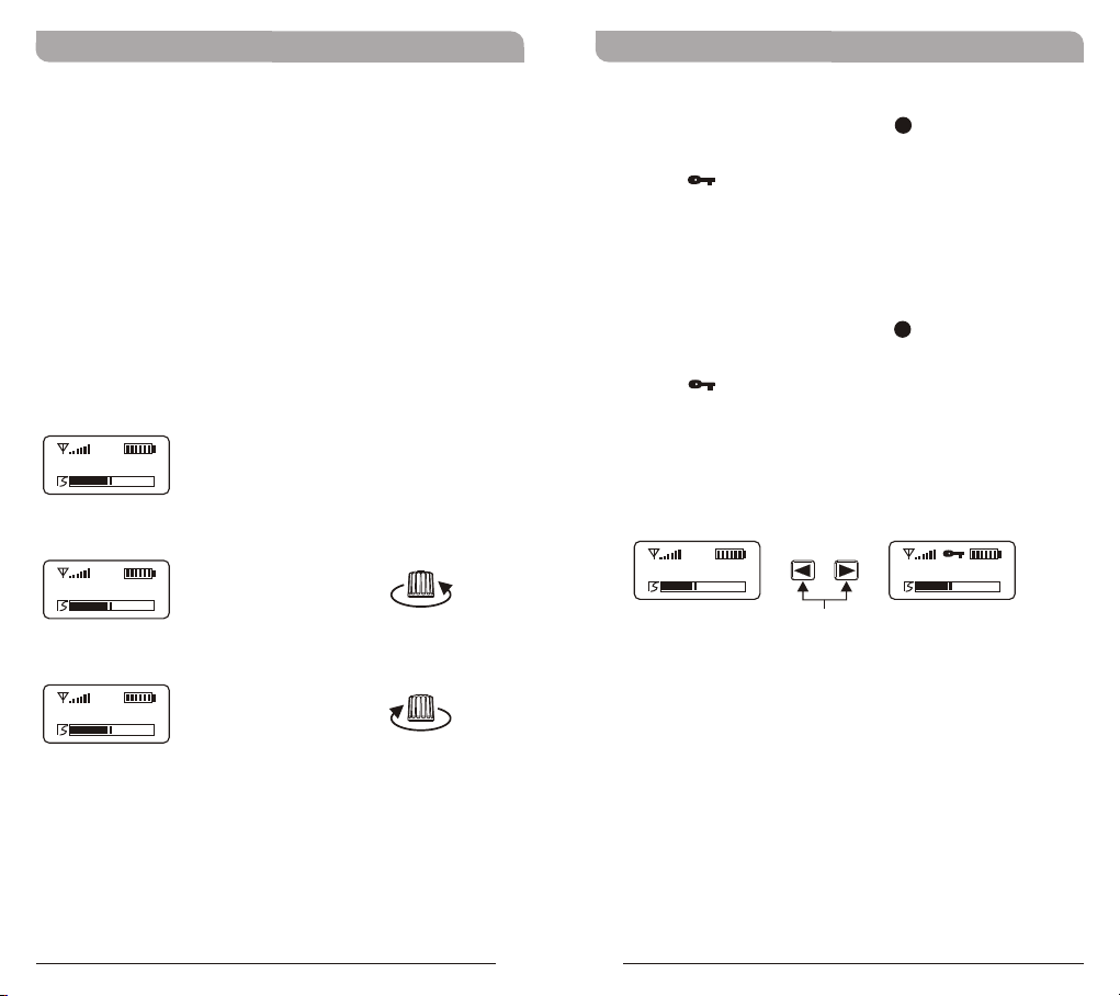
Volume Control
!
Insert the earphones or headphones and slowly
turn up the volume to a comfortable, safe sound
level.
!
"Mute" is lowest volume level. "VOL 20" is
highest volume level.
Warning
! Avoiding Hearing Damage - Permanent
hearing loss may occur if earphones or
headphones are used at high volume. Set the
volume to a safe level.
Mu te
VO L 9
VO L 2 0
" "No Sound
"Lower Volume"
" "Increase Volume
To Lock Receiver Channel:
!
Press and hold both buttons for approx. 3
7
seconds.
!
The " " icon then appears on the display. The
receiver channel is now locked and the ability to
change channels manually is inoperative.
To Unlock Receiver Channel:
!
Press and hold both buttons for approx. 3
7
seconds.
!
The " " icon disappears. The receiver channel
is now unlocked. Pressing the buttons will now
allow the user to manually change the receiver
channel UP/DOWN as normal.
CH 08CH 08
Press and Hold Buttons Simultaneously
6
7
Page 8
Digital Wireless T our Guide S ystem Digital Wireless T our Guide S ystem
868.125
MHz
Setting Up Transmitter
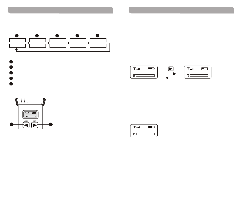
Press "MODE" button for one of the five functions.
a
CH 05
a
Channel
b
Frequency
c
Sensitivity Level
d
Audio Input Source
e
RF Output Power
15
b
868.500MHz
c
Gain 0dB
16
d
InPut Line
e
RF Mid
Channel Set-Up
!
Press MODE button until CH mode appears.
!
Press SET button once to activate function. CH
00 blinks once when activated.
!
Press SET button increases the channel number
by one.
!
Press MODE button to confirm and save the
change.
CH 01 CH 16
Frequency
! The displayed frequency corresponds to the
selected channel number. Frequency cannot be
changed.
86 8.1 25
MHz
8
9
Page 9
Digital Wireless T our Guide S ystem Digital Wireless T our Guide S ystem
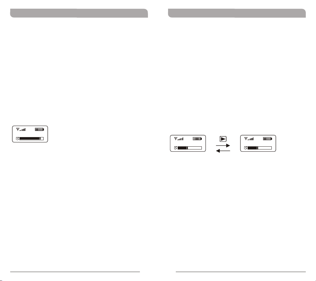
Sensitivity Level Set-Up
Gain Levels: Microphone Input (-12dB~9dB)
!
Line Input (-12dB~3dB).
Press MODE button until Gain mode appears.
!
Press SET button once to activate function. Gain
!
0 dB blinks once when activated.
Press SET button for -12, -9, -6, -3, 0, or 3 dB.
!
Press MODE button to confirm and save the
!
change.
Note:
* Approximately 70% of the level indicator is
optimal and recommended.
Gain- 9dB
Audio Input Source Set-Up
!
Press MODE button until InPut mode appears.
!
Press SET button once to activate function. InPut
Mic or Line blinks once when activated.
!
Press SET button for either Mic (Microphone) or
Line (Line ).
!
Press MODE button to confirm and save the
level
change.
Note:
* Mic-level provides biased power for electret
condenser microphone.
* Line-level provides audio transmission of
MP3/CD/DVD player.
InPut Line InPut Mic
10
11
Page 10
Digital Wireless T our Guide S ystem Digital Wireless T our Guide S ystem
RF Output Power Set-Up
! Press MODE button until RF mode appears.
! Press SET button once to activate function. RF
Hi, Mid or Low blinks once when activated.
! Press SET button for Hi, Mid or Low power.
! Press MODE button to confirm and save the
change.
Notes:
* Low or Mid setting is recommended for indoor,
smaller environment.
* Hi setting has 10mW RF power output.
RF LowRF MidRF Hi
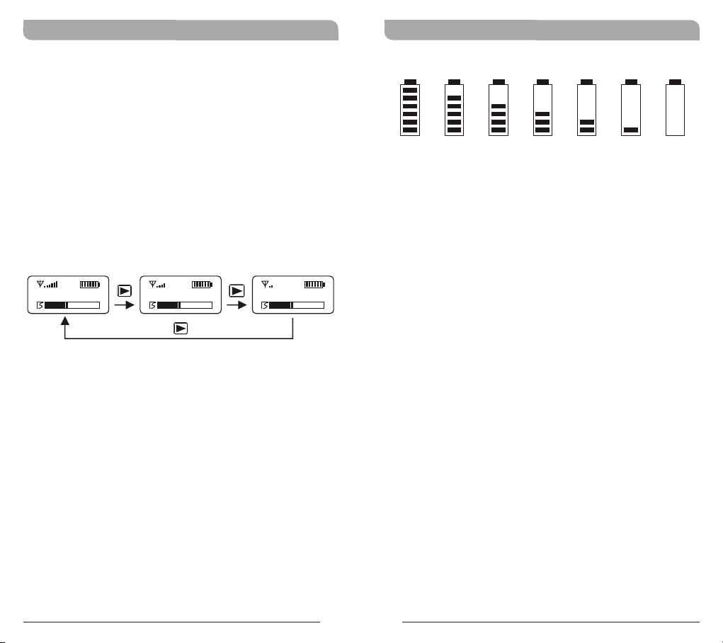
Battery Level Status
10 0% 80 % 60 % 40 % 20 % 10 %
Flashes
Change to new, fresh battery when zero or one
level indicator (10%) remains or when the battery
icon is flashing indicating a lower battery level.
Power will shut-off automatically if continuous use
without changing to protect from being overly
discharged.
Note:
!
The portable receiver and transmitter are
equipped with a programmable automatic shut-
off timer which, upon expiration will turn off.
!
The shut-off timer is pre-programmable with
MIPRO PC interface software and is currently
factory set for a duration of 6 hours (360
minutes).
!
Thirty (30) seconds before the shut-off timer
elapses a TIME OUT message will appear on the
LCD screen and then it will be powered off
automatically to conserve the battery.
12
13
Page 11
Digital Wireless T our Guide S ystem Digital Wireless T our Guide S ystem
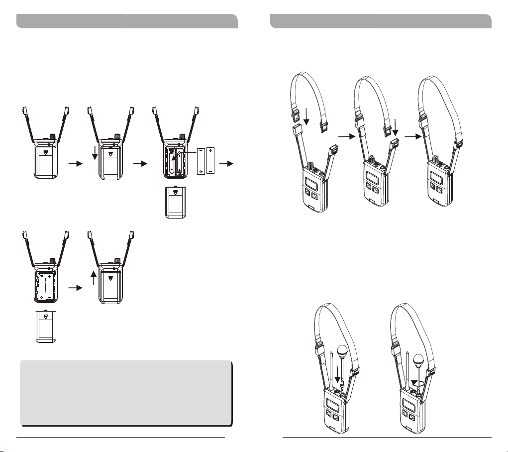
Battery Removal and Installation
! Slide the battery latch down and lift out of the
battery cover.
! Place new, fresh 2 "AA" batteries into the slots
and slide up until the latch locks into place.
Wearing Neck Lanyards
Insert into both side-release buckles and adjust the
straps for ideal length.
MTG-100Ta Transmitter Audio Input
MM-202P: Mini-Gooseneck Microphone (once
plugged, it can be used as a handheld)
Insert & fasten the optional MM-202P microphone.
Select MODE and Input Mic.
Caution:
Remove the batteries if unused for a long
period of time to prevent battery leakage,
corrosion and causes possible damage to
electronics.
14
15
Page 12
Digital Wireless T our Guide S ystem Digital Wireless T our Guide S ystem
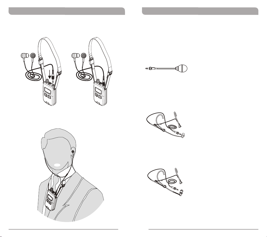
MTG-100Ra Receiver Audio Input
Optional Microphone Accessories for
MTG-100Ta Transmitters
MM-202P: Mini-Gooseneck Microphone with 3.5mm
screw-lock plug.
MU-101P: Headworn Microphone with 3.5mm
screw-lock plug.
MU-53HNP: Premium Headworn Microphone with
3.5mm screw-lock plug.
16
17
Page 13
Digital Wireless T our Guide S ystem Digital Wireless T our Guide S ystem
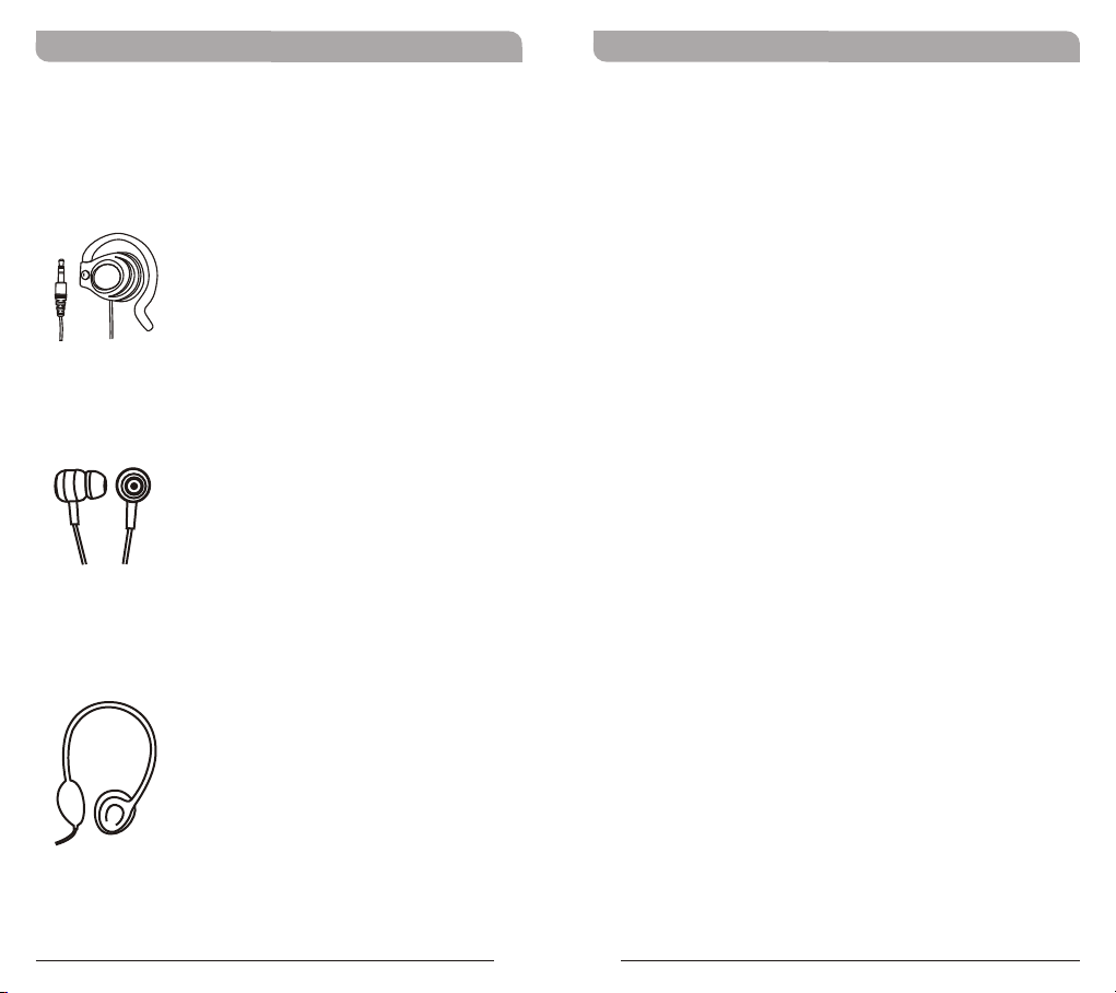
Optional Earphone Accessories for MTG-100Ra
Receivers
E-5S: Single-sided Earphone with 3.5mm mini-jack
plug
E-10S: Stereo Earphones with 3.5mm mini-jack
plug
E-20S: Stereo Headphones with 3.5mm mini-jack
plug
18
19
 Loading...