

Mipro Electronics Co ACT80TC18 Users manual
ACT-80TC
DIGITAL TRANSMITTER
User Guide
All rights reserved.
Do not copy or forward without prior approvals MIPRO.
Specifications and design subject to change without notice.
MN 015/01
2 CE 5 1 5 A
Rechargeable Digital Wideband Bodypack Transmitter Rechargeable Digital Wideband Bodypack Transmitter
Contents Bodypack Controls and Indicators
1 Bodypack Controls and Indicators
4 O
5 LCD
perating Instructions
Display Screen
1
2
6
How to Setup Transmitter Parameters
19 Battery Status
21
25 AF
26 B
MUTE Control Set-Up
Input Connections
attery Removal and Installation
3
4
5
6
7
8
9
10
11
12
FREQ UENCY
485.000MHz
ON MODE
13
SET
14
15
0
1
Rechargeable Digital Wideband Bodypack Transmitter Rechargeable Digital Wideband Bodypack Transmitter
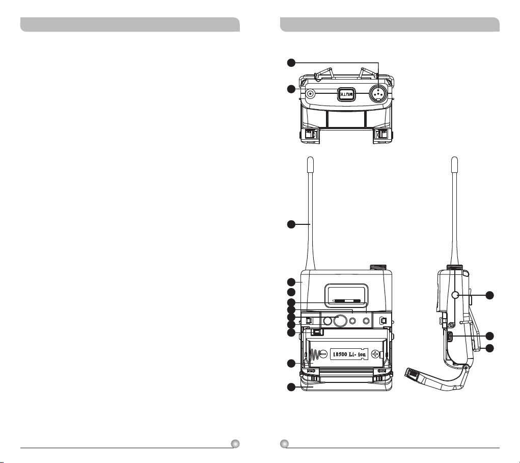
1
Audio Input Connector: TA4F mini 4-pin
connector accepts any MIPRO lavalier,
instrument and headset microphones and
cables. (See 5 ways of connection on AF Input
Connections)
2
MUTE Button: To mute and un-mute the audio
signal temporary.
3
Antenna: Flexible 1/ 4 wave transmitting
antenna.
4
Transmitter Housing: Holds PCB board and
wires.
5
LCD Panel: Display transmitter parameters.
6
SET Button: Parameter selection button.
7
MODE Button: Allows access to available
functions displaying in LCD panel.
8
ACT IR Port: Align and syncs the transmitter
and receiver frequency automatically.
9
Power Button: Press and hold 2 seconds to
power ON or OFF.
10
Battery Circuitry Protection Reset Button
11
Battery Compartment: Accommodates one
18500 rechargeable battery.
12
Battery Cover: Hinged cover opens to provide
access to one 18500 rechargeable battery.
13
External Mute Connector: When an external
mute switch cable, MJ-70 (optional) is connected
, user can manually mute and un-mute the
audio temporary.
14
Battery Charging Contact: Align contacts
during charging.
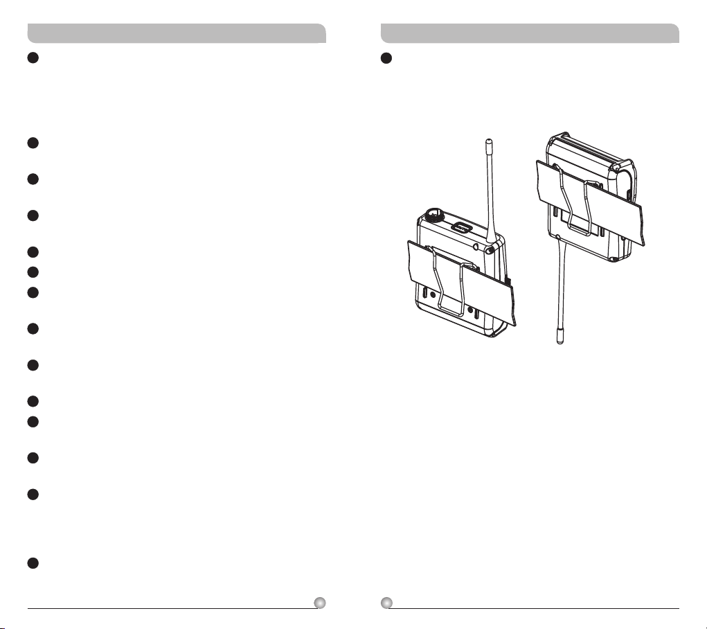
15
Belt Clip: Detachable and reversible design
allows the transmitter to be worn on a belt,
waistband, or guitar strap ( .Figure 1)
(Positive Wear)
(Opposite Wear)
32
(Figure 1)
Rechargeable Digital Wideband Bodypack Transmitter Rechargeable Digital Wideband Bodypack Transmitter
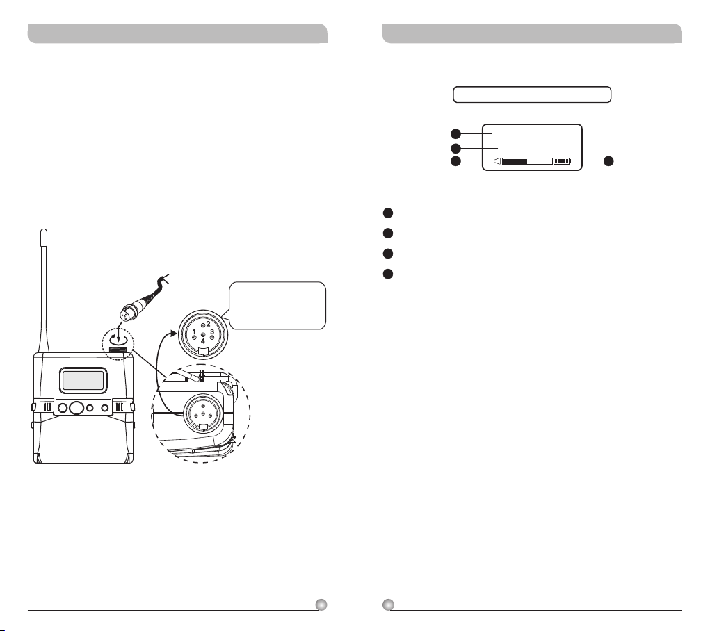
Operating Instructions
!
Insert the lavalier, headset microphone or
instrument cable into the audio input connector
before power ON the transmitter.
Tighten the connector screw clockwise direction
!
as shown in (Figure 2) for a secured fit.
! Please make sure sensitivity level is set at
proper level.
Capsule Connector
Headset
ON MODE
Lavalier
SET
The ridge on the
connector must align and
match the indentation on
the socket when inserting
for a proper fit.
(Figure 2)
LCD Display Screen
Fully Lit LCD Display
14
15
16
14
LCD Screen
15
Parameters Screen
16
AF (audio) MUTE
17
Transmitter Battery Meter
GRP CH
0 1 0 2
17
4
5
Rechargeable Digital Wideband Bodypack Transmitter Rechargeable Digital Wideband Bodypack Transmitter
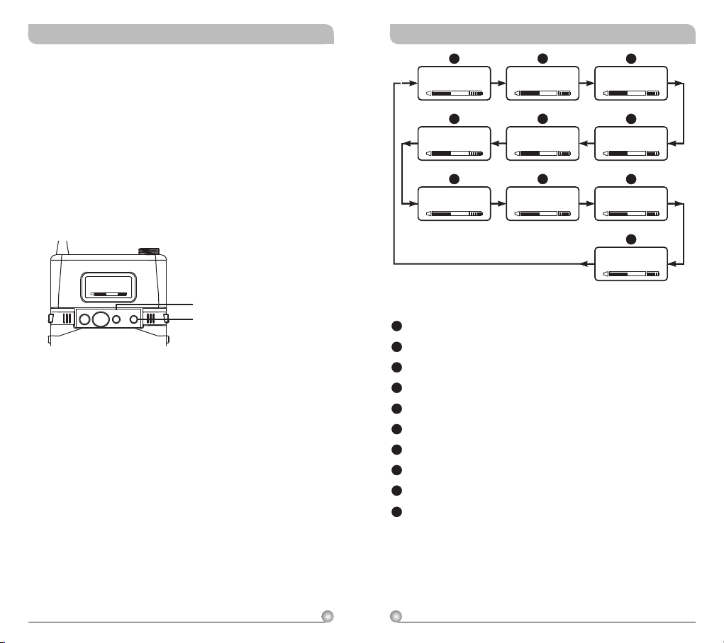
How to Setup Transmitter Parameters
! MODE Button:
Press “MODE” button to access one of the NINE
functions below.
! SET Button:
Press “SET” button and LCD wills start flashing.
During flashing, press SET button to change
parameters.
FREQU ENCY
485.000MHz
ON MODE
SET
MODE
SET
A
GRP CH
0 1 0 2
F
ENC RYPTIO N
N O
G
RF P OWER
RF-L O W
A
Group and Channel
B
Frequency
C
Sensitivity Level
D
AF Low Cut
E
AF Limit
F
Encryption
G
RF Output Power
H
AF Phase
I
Parameters Lock & Unlock Status
J
MUTE MODE
B
FRE QUENC Y
485.000MHz
E
AF L IMIT
Y E S
H
AF P HASE
INVE R T
C
AF G AIN
0 dB
D
AF L OW-CU T
LOW CUT
I
SET LOCK
UNLO C K
J
MUT E MODE
MANU A L
6
7
Rechargeable Digital Wideband Bodypack Transmitter Rechargeable Digital Wideband Bodypack Transmitter
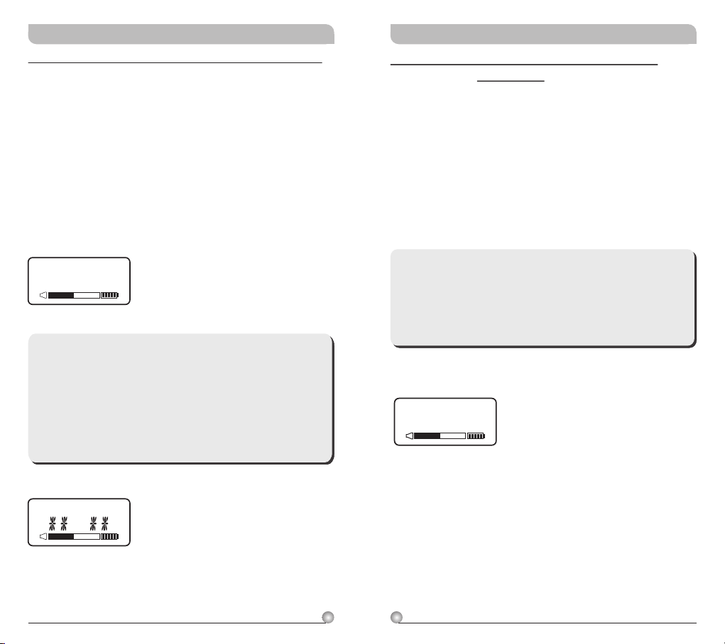
GRP CH: Displays Group and Channel Information
a. Press MODE and stop on the GRP CH function;
the display showing the current group and
channel will be flashing. After 5 seconds, the
display will stop flashing and the current group
and channel selection will be set.
b. The group and channel information is now
shown on the display. Changing the current
group and channel must be done on the
receiver.
GRP CHGRP CH
0 1 0 2
**Note:
When programming a special frequency via
monitoring software, the LCD screen cannot
display the number. This is because this special
channel is not in the preset group and channel.
RF, the LCD panel will look like the illustration
below.
FREQUENCY: Displays Transmitter Frequency
Information
a. Press MODE and stop on the FREQUENCY
function; the display showing the current
frequency will be flashing. After 5 seconds, the
display will stop flashing.
b. The frequency information is now shown on the
display. Changing the current frequency must be
done on the receiver.
**Note:
To modify the transmitter's group, channel and
frequency, all three must be set at the receiver
and the new setting transmitted to the
transmitter via the ACT function.
FR EQ UE NC Y
485.000MHz
GRP CH
8
9
 Loading...