

Mipro Electronics Co ACT80T18 Users manual

2 CE 4 6 4 A
MIPRO Electronics Co., Ltd.
Headquarters: 814 Pei-Kang Road, Chiayi, 60096, Taiwan.
Web: www.mipro.com.tw
E-mail: mipro@mipro.com.tw
ACT-80T Wideband Digital
Bodypack Transmitter
User Guide
Design and specifications are subject to change without prior notice
AS120901

FCC
This device complies with Part 15 of the FCC Rules. Operation
is subject to the following two conditions:
(1) This device may not cause harmful interference, and
(2) This device must accept any interference received,
including interference that may cause undesired operation.
This device complied with FCC radiation exposure limits as set
forth for an uncontrolled environment.
This device should be installed and operated so that its
antenna(s) are not co-located or operating in conjunction with
any other antenna or transmitter
FCC Caution: To assure continued compliance, any changes or
modifications not expressly approved by the party responsible
for compliance could void the user's authority to operate this
equipment. (Example - use only shielded interface cables
when connecting to computer or peripheral devices).
IC
This device complies with Industry Canada’s RSSs. Operation
is subject to the following two conditions:
(1) This device may not cause interference; and
(2) This device must accept any interference, including
interference that may cause undesired operation of the
device.
Le présent appareil est conforme aux CNR d’Industrie Canada
applicables aux appareils radio. L’exploitation est autorisée
aux deux conditions suivantes :
(1) l’appareil ne doit pas produire de brouillage;
(2) l’utilisateur de l’appareil doit accepter tout brouillage
radioélectrique subi, même si le brouillage est susceptible
d’en compromettre le fonctionnement.
Disposal
2005 -08- 13
Dispose of any unusable devices or batteries
responsibly and in accordance with any
applicable
Disposing of used batteries with domestic waste
to be avoided!
is
Batteries / NiCad cells often contain heavy
metals such as cadmium(Cd), mercury(Hg) and
lead(Pb) that makes them unsuitable for
disposal with domestic waste. You may return
spent batteries/ accumulators free of charge to
recycling centres or anywhere else
batteries/accumulators are sold.
By doing so, you contribute to the conservation
of our environment!
regulations.
Digital Bodypack Transmitter
Contents
1 Key Features
3 Bodypack Controls and Indicators
6 O
7 LCD
8
19 Battery Status
22
26 AF
27 B
0
perating Instructions
Display Screen
How to Setup Transmitter Parameters
MUTE Control Set-Up
Input Connections
attery Removal and Installation

Digital Bodypack Transmitter Digital Bodypack Transmitter
Key Features
! Industry's smallest and lightest digital bodypack
transmitter with extremely rugged low-profile
metal housing.
! Detachable antenna, XLR input socket, mute
button and remote mute control input.
! Backlit LCD displays working band-code, group
channel, AF gain, limiter, low cut, phase, output
power, mute, battery status, encryption status &
error codes.
! Innovatively designed battery cover allows easy
access to operate buttons and prevents
accidental operation.
! Mute button and remote-control jack is equipped
for easy activation of mute function.
! High efficiency, low power consumption and low
spurious PLL synthesized circuit is applied.
! An interference-free working channel can be
synchronized quickly and precisely by MIPRO's
patented ACT™ function.
! Selectable AF input polarity for various
microphone capsule modules.
! Mini-XLR input connector for quick screw lock
with lavalier / headworn mics and guitar.
! 2 AA batteries for long operation time.
! Adjustable belt clip allows wearing transmitter in
any position.
Furnished Accessories:
! USER GUIDE ×1
1
2
Digital Bodypack Transmitter Digital Bodypack Transmitter
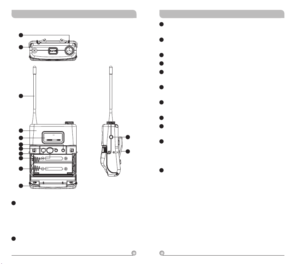
Bodypack Controls and Indicators
1
2
3
4
5
6
7
8
9
10
11
GROUP CHAN
0 1 02
MODEON
SET
3
Antenna: Flexible 1/ 4 wave transmitting
antenna.
4
Transmitter Housing: Holds PCB board and
wires.
5
LCD Panel: Display transmitter parameters.
6
SET Button: Parameter selection button.
7
MODE Button:
Allows access to 9 available
functions displaying in LCD panel.
8
Power Button: Press and hold 2 seconds to
power ON or OFF.
9
ACT IR Port: Align and syncs the transmitter
and receiver frequency automatically.
10
Battery Compartment: Holds 2 'AA' batteries.
11
Battery Cover: Hinged cover opens to provide
12
13
access to 2 'AA' batteries.
12
External Mute Connector: When an external
mute switch cable, MJ-70 (optional) is
connected, user can manually mute and unmute the audio temporary.
13
Belt Clip: Detachable and reversible design
allows the transmitter to be worn on a belt,
waistband, or guitar strap ( .
Figure 1)
1
Audio Input Connector: TA4F mini 4-pin
connector accepts any MIPRO lavalier,
instrument and headset microphones and
cables. (See 5 ways of connection on AF Input
Connections)
2
MUTE Button: To mute and un-mute the audio
signal temporary.
43
Digital Bodypack Transmitter Digital Bodypack Transmitter
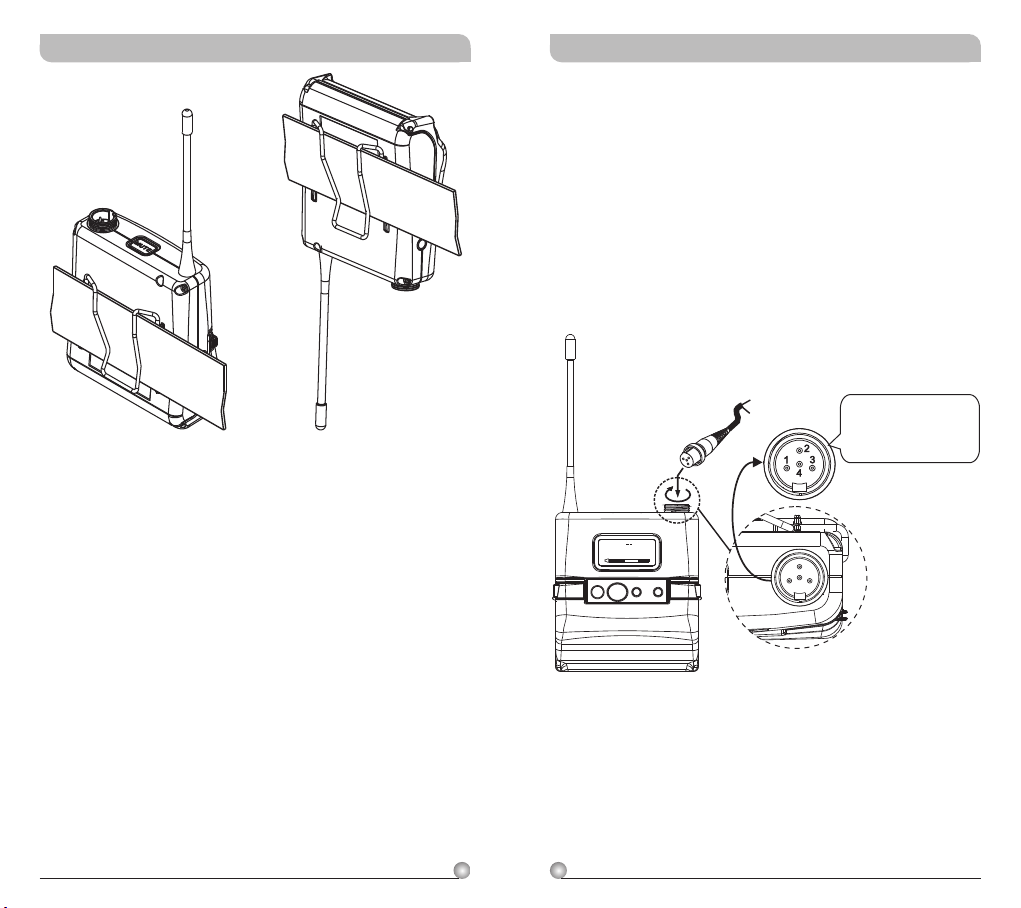
(Positive Wear) (Opposite Wear)
(Figure 1)
Operating Instructions
! Please make sure sensitivity level is set at
proper level.
! Guitar setting is recommended at LINE level.
!!Insert the lavalier, headset microphone or
instrument cable into the audio input connector
before power ON the transmitter.
Tighten the connector screw clockwise direction
as shown in (Figure 2) for a secured fit.
Capsule Connector
GROUP CHAN
0 1 02
MODEON
Headset
Lavalier
SET
The ridge on the
connector must align and
match the indentation on
the socket when inserting
for a proper fit.
(Figure 2)
5
6
Digital Bodypack Transmitter Digital Bodypack Transmitter
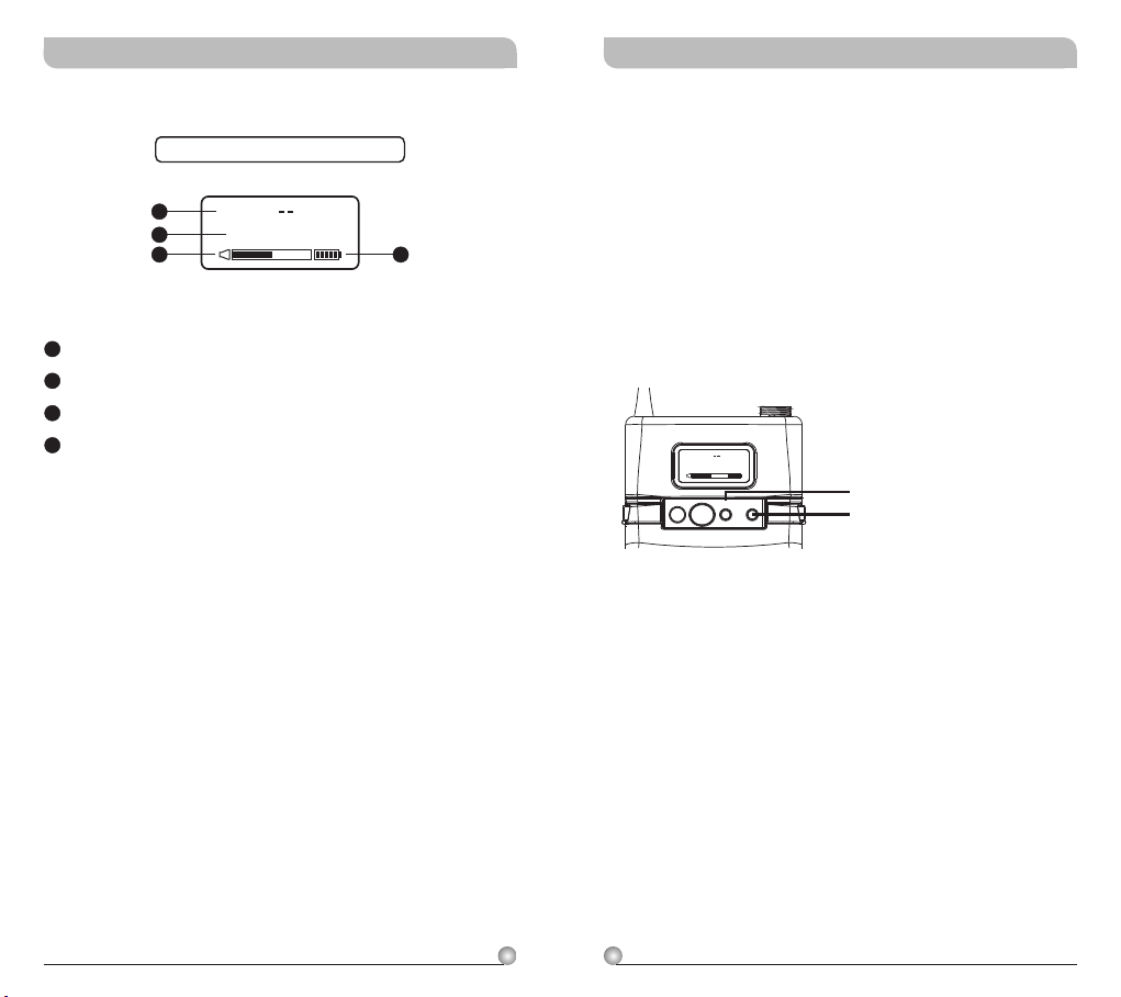
LCD Display Screen
Fully Lit LCD Display
14
15
16
14
LCD Screen
15
Parameters Screen
16
AF (audio) MUTE
17
Transmitter Battery Meter
GR OU P C HA N
0 1 0 2
How to Setup Transmitter Parameters
! MODE Button:
Press “MODE” button to access one of the NINE
functions below.
! SET Button:
17
Press “SET” button and LCD wills start flashing.
During flashing, press SET button to change
parameters.
GROUP CHAN
0 1 02
SET
MODEON
MODE
SET
7
8
 Loading...