

MIPRO ACT-52T User Manual
User Guide
2 CE 5 2 2 A
ACT-52T Bodypack Transmitters
All rights reserved.
Do not copy or forward without prior approvals MIPRO.
Specifications and design subject to change without notice.
MN 014/07
Bodypack Transmitter Bodypack Transmitter
Contents
1 Bodypack Controls and Indicators
3 O
4 LCD
5 T
12 Battery Status
13
15 AF
16 B
perating Instructions
Display Screen
ransmitter Parameters
MUTE Control Set-Up
Input Connections
attery Removal and Installation
Bodypack Controls and Indicators
1
2
3
4
5
6
7
8
9
10
11
CH GRP
CH GRP
07 03
07 03
12
13
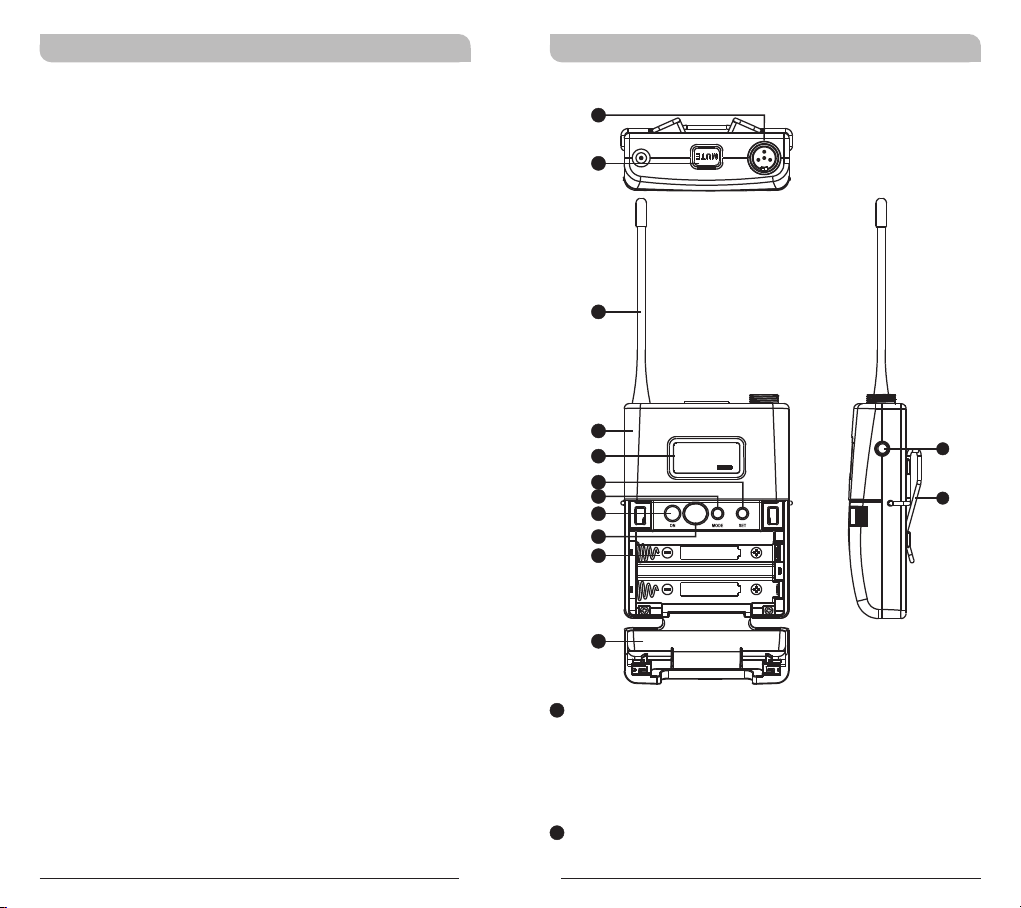
1
Audio Input Connector: TA4F mini 4-pin
connector accepts any MIPRO lavalier,
instrument and headset microphones and
cables. (See 5 ways of connection on AF Input
Connections)
2
MUTE Button: To mute and un-mute the audio
signal temporary.
0
1
Bodypack Transmitter Bodypack Transmitter
3
Antenna: Flexible 1/4 wave transmitting
antenna.
4
Transmitter Housing: Holds PCB board and
wires.
5
LCD Panel: Display transmitter parameters.
6
SET Button: Parameter selection button.
7
MODE Button: Allows access to 6 available
functions displaying in LCD panel.
8
Power Button: Press and hold 2 seconds to
power ON or OFF.
9
ACT IR Port: Align and syncs the transmitter
and receiver frequency automatically.
10
Battery Compartment: Holds 2 'AA' batteries.
11
Battery Cover: Hinged cover opens to provide
access to 2 'AA' batteries.
12
External Mute Connector: When an external
mute switch cable, MJ-70 (optional) is
connected, user can manually mute and unmute the audio temporary.
13
Belt Clip: Detachable and reversible design
allows the transmitter to be worn on a belt,
waistband, or guitar strap ( .Figure 1)
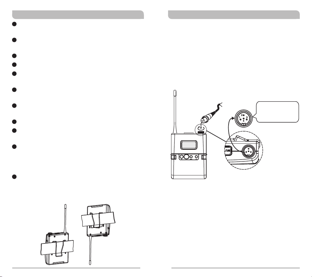
Operating Instructions
!!Insert the lavalier, headset microphone or
instrument cable into the audio input connector
before power ON the transmitter.
Tighten the connector screw clockwise direction
as shown in (Figure 2) for a secured fit.
Capsule Connector
Headset
Lavalier
The ridge on the
connector must align and
match the indentation on
the socket when inserting
for a proper fit.
(Figure 2)
(Positive Wear)
(Figure 1)
(Opposite Wear)
2
3
07 03
CH GRP
Bodypack Transmitter Bodypack Transmitter
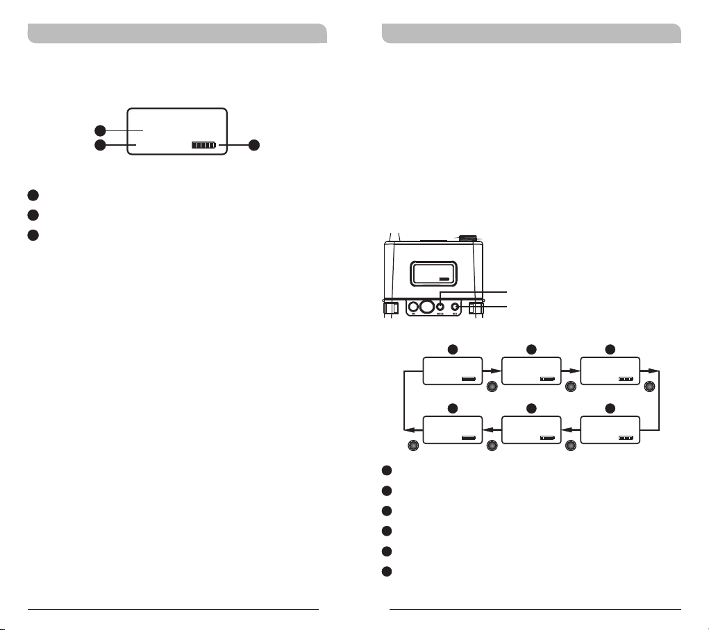
LCD Display Screen Transmitter Parameters
!
MODE button
Press “MODE” button to access one of the
6 parameters below.
SET button
!
Press “SET” button then the changeable
functions will twinkle. Change to the desired
parameters during the above twinkle by pressing
“SET” button.
MODE
SET
A1
A2
A1
LCD Screen
A2
AF (audio) MUTE
A3
Transmitter Battery Meter
AF MUTE
CH GRP
07 03
A3
A
GRP CH
07 03
AF MUTE AF MUTE AF MUTE
F
SET LOCK
UNLOCK
MODE
AF MUTE AF MUTE
A
Group and Channel
B
Frequency
C
Sensitivity Level
D
RF Output Power
E
MUTE Mode
F
Parameters Lock & Unlock Status
4
5
B
FREQUENCY
802.000MHz
MUTE MODE
MANUAL
MODE MODEMODE
E
MODEMODE
C
AF GAIN
0 dB
D
RF POWER
RF-LOW
AF MUTE
 Loading...