

MIPRO ACT-311 User Manual
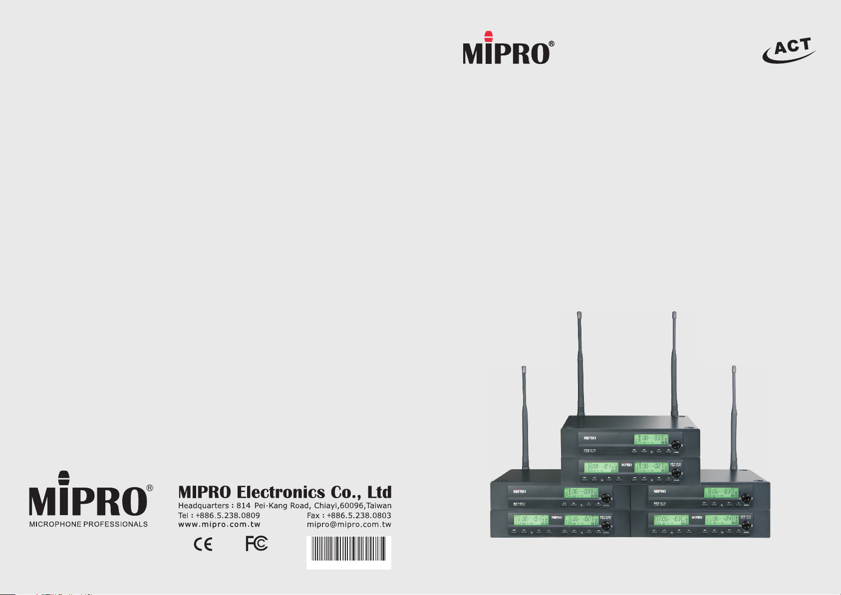
ACT 3-Series
2 CE 3 8 8 E
Diversity Wireless Microphone Systems
User Guide
All rights reserved. Do not copy or forward without prior approvals MIPRO.
Specifications and design subject to change without notice. MN 013/11
! IMPORTANT SAFETY INSTRUCTIONS !
WARNING
1. Read these instructions.
2. Keep these instructions.
3. Heed all warnings.
4. Follow all instructions.
5. Do not use this apparatus near water.
6. Clean only with a dry cloth.
7. Do not block any ventilation openings. Install in accordance with the manufacturer's
instructions.
8. Do not install near any heat sources such as radiators, heat registers, stoves, or
other apparatus (including amplifiers) that produce heat.
9. Do not defeat the safety purpose of the polarised or ground plug: A polarised plug
has two blades with one wider than the other. The wide blade is provided for your
safety. When the provided plug does not fit into your outlet, consult an electrician
for replacement of the obsolete outlet.
10. Protect the power cord from being walked on or pinched particularly at plug,
convenience receptacles, and the point where they exit from the apparatus.
11. Only use attachments/accessories specified by the manufacturer.
12. Use only with a cart, stand, tripod, bracket, or table specified by the
manufacturer, or sold with the apparatus. When a cart is used, use
caution when moving the cart/apparatus combination to avoid injury
from tip-over.
13. Unplug this apparatus during lightning storms or when unused for long
periods of time.
14. Refer all servicing to qualified service personnel. Servicing is required
when the apparatus has been damaged in any way, such as power-supply
cord or plug is damaged, liquid has been spilled or objects have fallen into
the apparatus, the apparatus has been exposed to rain or moisture, does not
operate normally, or has been dropped.
15. To reduce the risk of fire or electric shock, do not expose this apparatus to rain or
moisture.
16. Apparatus should not be exposed to dripping or splashing and no objects filled with
liquids, should be placed on the apparatus.
17. Use only with the battery which specified by manufacturer.
18. The power supply cord set is to be the main disconnected device.
1. FOR OUTDOOR USE:
To reduce the risk of fire or electric shock, do not expose this apparatus to rain or
moisture.
2. UNDER WET LOCATION:
Apparatus should not be exposed to dripping or splashing and no objects filled with
liquids, such as vases should be placed on the apparatus.
3. SERVICE INSTRUCTIONS:
CAUTION - These servicing instructions are for use by qualified service personnel
only. To reduce the risk of electric shock, do not perform any servicing other than
that contained in the operating instructions unless you are qualified to do so.
This symbol indicates that dangerous voltage constituting a risk of electric
shock is present within this unit.
This symbol indicates that there are important operating and maintenance
instructions in the literature accompanying this unit.
& IC - ID
THIS DEVICE COMPLIES WITH PART15 OF THE FCC RULES AND RSS-123 ISSUE2 OF
CANADA. OPERATION IS SUBJECT TO THE FOLLOWING TWO CONDITIONS:
(1) This device may not cause interference.
(2) This device must accept any interference, including interference that may cause
undesired operation of the device. This equipment complies with FCC RF radiation
exposure limits set forth for an uncontrolled environment.
Disposal
2005 -08-1 3
Dispose of any unusable devices or batteries responsibly and in accordance
with any applicable regulations.
Disposing of used batteries with domestic waste is to be avoided!
Batteries / NiCad cells often contain heavy metals such as cadmium(Cd),
mercury(Hg) and lead(Pb) that makes them unsuitable for disposal with
domestic waste. You may return spent batteries/ accumulators free of
charge to recycling centres or anywhere else batteries/accumulators are
sold.
By doing so, you contribute to the conservation of our environment!

Diversity Wireless Systems Diversity Wireless Systems
Contents
1 Product Overview
3 Key Features and Benefits
4 MIPRO's Proprietary "ACT" Function & Operation
5 Receiver Controls and Indicators - Front Panel
6 Receiver LCD Interface
7 Receiver Controls and Indicators - Rear Panel
9 Receiver Installation
10 Receiver Operating Tips
11 Rackmount Installation for Receivers
13 Receiver Parameters
20 Dimming & Lit Display Mode
22 Wireless Accessories & Replacement Parts
Product Overview
MIPRO is a leading manufacturer of truly innovative wireless microphone systems. No
other brands can match the easy set-up of MIPRO’s industry’s first AutoScan and
patented ACT (Automatic Channel Targeting) channel sync set-up technology.
MIPRO’s ACT systems are built to handle tough conditions, delivering superb RF
reliability and transparent audio performance in a wide variety of professional venues
and applications.
23 General Tips for Improving System Performance
24 Troubleshooting
0
1
Diversity Wireless Systems Diversity Wireless Systems
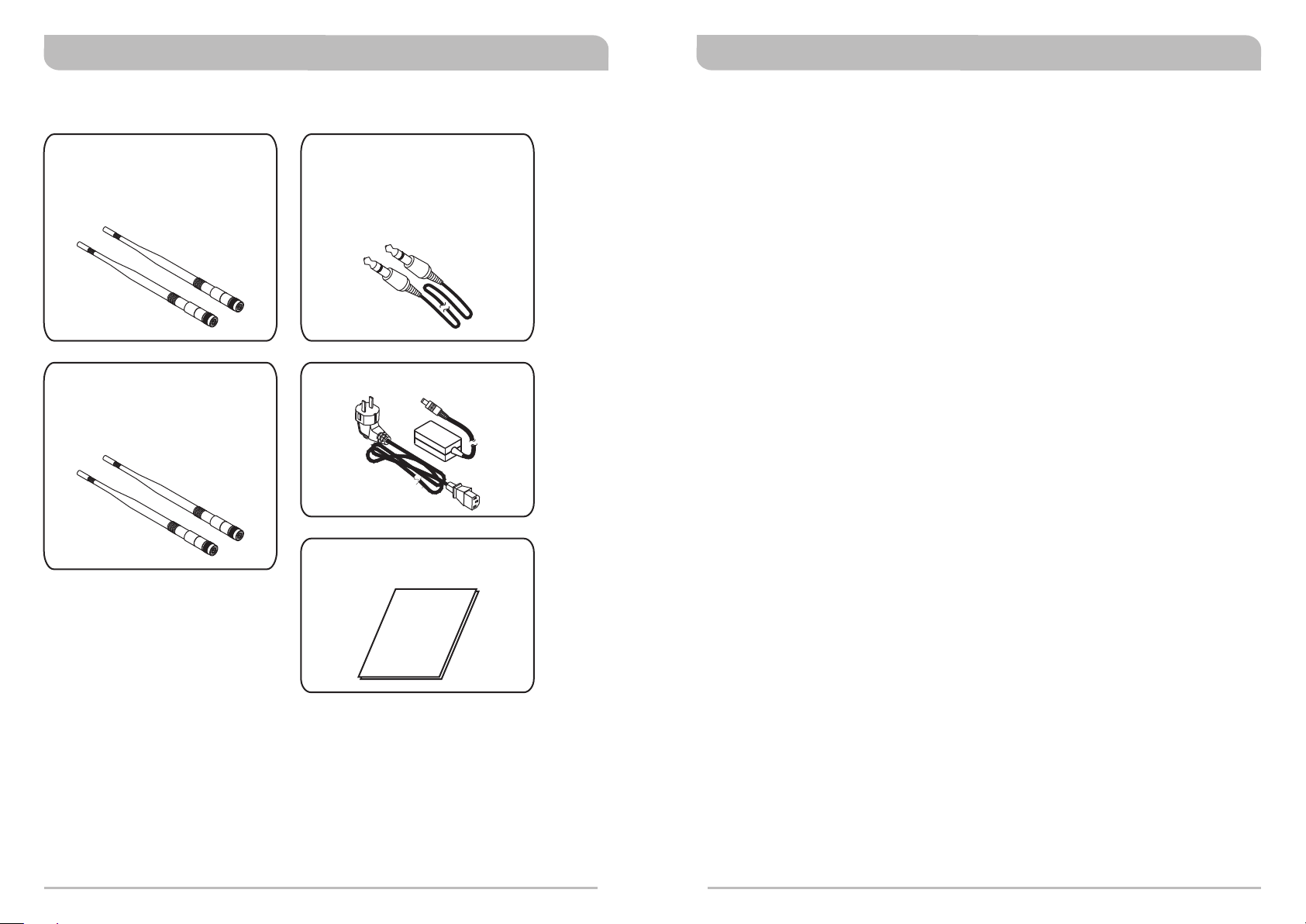
Receiver Accessories Included
Detachable 1/2 Wave Antenna ×2 Audio Output Cable
(1-pc for ACT-311B & ACT-312B
ACT-311 & ACT-312)
(2-pcs for ACT-311BT & ACT-312BT
ACT-311T & ACT-312T)
Optional
Detachable 1/2 Wave Antenna
(4-pcs for ACT-311BT & ACT-312BT
ACT-311T & ACT-312T)
Power Supply with Cable ×1
User Guide ×1
Key Features and Benefits
Single, dual & quad channels in EIA standard 1/2 & 1-RU metal housing.
!
Diversity technology for optimum reception.
!
961 channels across 24 MHz band. (except EU/ISM 863~865MHz range)
!
Up to 8 preset compatible channels in each band. (except EU/ISM 863~865MHz
!
band)
One-touch AutoScan for a clear, interference-free receiver frequency.
!
MIPRO's patented ACT feature and now, industry standard, facilitates simple
!
frequency synchronization between receiver and transmitter
Advanced multi-function backlit LCD for clear visibility and displays RF/Audio/
!
transmitter battery/squelch meters; A/B diversity & lock indicators; and Group,
Channel and Frequency.
Programmable Group, Channel, Frequency, Squelch and Lock functions.
!
Automatic brightness display during performance and idle.
!
Dual "PiloTone & NoiseLock" circuits minimize interference.
!
All parameters easily monitored in a single display for easy control and monitoring.
!
The receiver panel controls can be locked to prevent accidental changing of settings.
!
Industry's only interference 'warning' indicator and control to manage it.
!
Detachable antennas for front or rear panel installation.
!
Receiver provides bias voltage for MIPRO antenna booster systems.
!
Balanced XLR & unbalanced 1/4” audio outputs.
!
2
3
Diversity Wireless Systems Diversity Wireless Systems
MIPRO'S Proprietary "ACT" Function & Operation
What is ACT?
'ACT' stands for 'Automatic Channel Targeting'. MIPRO developed and patented this
innovative infrared (IR) sync technology in 2001. MIPRO was the first manufacturer in
the industry to automatically synchronize the frequency selected on the receiver to any
ACT handheld or bodypack transmitter on the same frequency band.
ACT Benefits:
!
No manual frequency adjusting needed, unlike traditional transmitters.
!
Simple, fast and precise frequency set-up without mechanical errors.
!
Once the frequency has been set, the data is stored in memory, meaning that the
frequency is set until it is changed by performing the 'ACT' function again, even
after powering off.
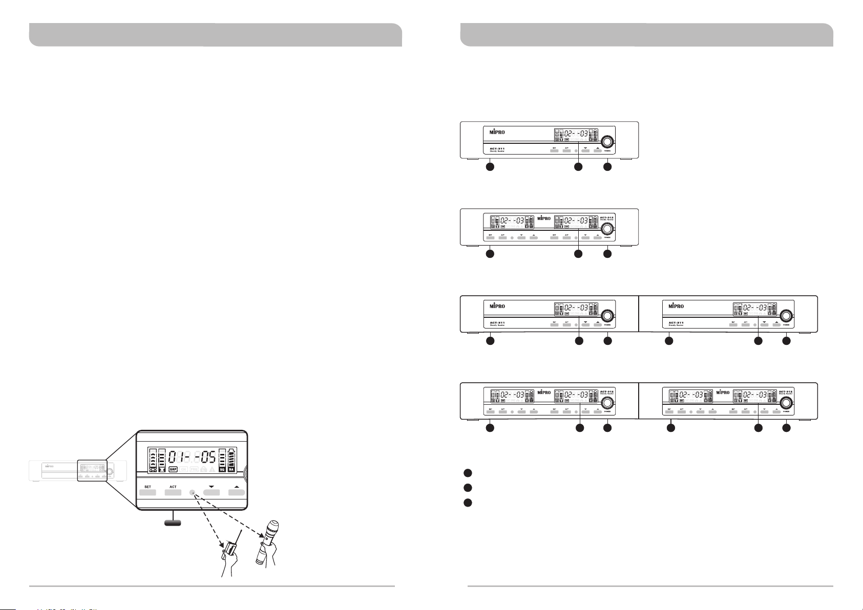
ACT Set-Up
!
Ensure a receiver channel is set-up and transmitter batteries are fresh, installed
correctly and powered-on.
!
Press the ACT button on the receiver to activate the ACT syncing function. Once
activated, the group/channel and working frequency start blinking.
!
Bring ACT handheld or bodypack transmitter within 30cm (12”) of the IR port on the
receiver. The IR port is located between the 'ACT' and “▼” buttons and indicated by
a round-shaped red color spot. The frequency will sync automatically.
!
When the frequencies are synchronized successfully between the receiver and
transmitter, the RF meter cursor and working frequency stop blinking and the
indicators in the RF meter are lit.
Receiver Controls and Indicators
Front Panel
ACT-311B/ACT-311 Single Channel
2 31
ACT-312B/ACT-312 Dual Channel
2 31
ACT-311BT/ACT-311T Dual Channel
2 23 31 1
ACT-312BT/ACT-312T Quad Channel
Press button to
ACT
facilitate simple frequency
synchronization between
receiver and transmitter
2 23 31 1
1
Receiver Panel: LCD screen and control buttons.
2
Receiver Display: LCD screen.
3
<
3
0
cm
(
1
2
i
n
.)
Power On/Off Button: Press and hold button to turn the receiver on and off.
or
4
5
 Loading...