

Page 1
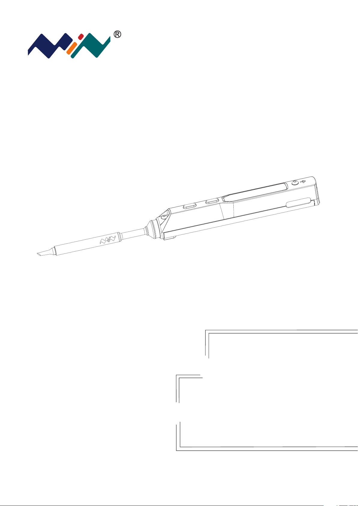
TS100 Soldering Iron
Instruction Manual
TS100
Version 1.0.1
Please read this manual before operating
the TS100(this instruction
manual is based on APPV2.11
Page 2
WARNING:Failure to comply a
WARNING may result in serious
!
injury to the user or others.
Content
1
Safety Statement
2
!
P1
Overview
CAUTION:Failure to comply
a CAUTION may cause damage
to the product or other equipments.
NOTE:Annotations,operation
notes or additional information.
P3
3
Power Adaptor
Selection
P5
6
4
Operation
P6
5
Trouble Shooting Guide
Soldering Iron Tip
P16
7
P14
Technical Support
P18
8
Legal Statements
P20
Page 3

1
1.1 General Safety
Safety Statememt
Use only certified power source/adaptors from your region.
(please refer to 3.0 for specifications)
Do not operate in humid environment.
Do not operate in inflammable/explosive environment.
1.2 Working condition
Working condition
Temperature
Keep the surface of the product clean and dry.
Requirements
Operating Condition: from 0℃ to +50℃
Non-operating Condition: from -20℃ to +60℃
Humidity
Operating Condition: from 40℃ to 50 ℃,0% to 60% RH
Operating Condition: from 0℃ to 40 ℃,10% to 90% RH
Non-operating Condition: from 40℃ to 60℃,5% to 60%RH
Non-operating Condition: Low temperature: from 0℃ to 40℃,
5% to 90%RH
1
Page 4
1
1.3 Warnings
Safety Statememt
When using TS100,
Turn the power off when not in use,or left unattended.
When power is ON,tip temperatures will between
100℃~400℃(212℉~752℉),please be careful.
Please don’t operate TS100 when it’s wet or operate
it with wet hands,which will cause an electric shock.
1.4 Cautions
When using TS100,
• The handle is constructed with precision, dropping shall be avoided.
• After continuous use up to 40 minutes, the handle surface temperature
!
will reach 50℃~60℃.
• For the first time using, TS100 may generate a light smoke due to the
heating of heating elements, which is a normal phenomenon.
1.5 Liability Statement
Any damage of the product,or losses related to the product damage,
if it’s man-caused,or assumed to be man-caused,the liability will belong to
the user.
2
Page 5
Overview
2
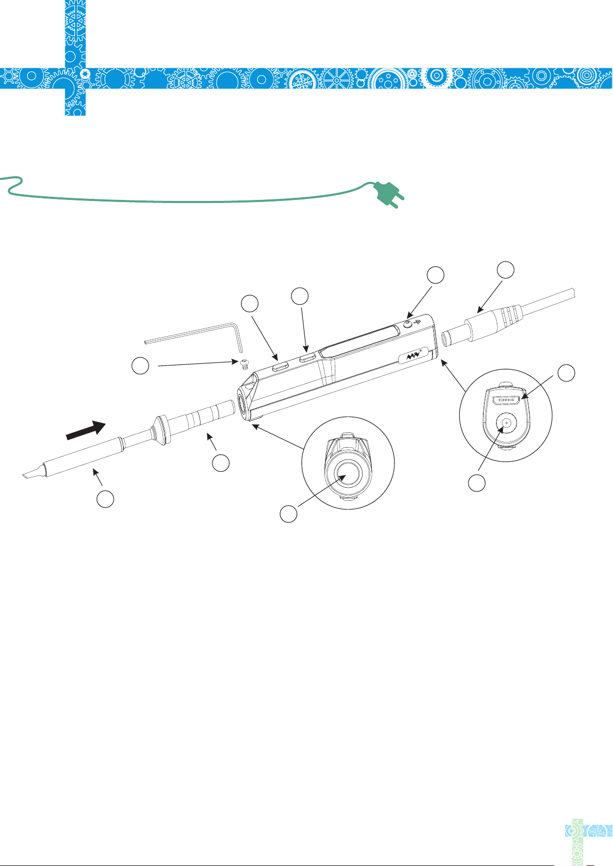
2.1 Ports and Control Panel Introduction
10
4
2
1
9
3
8
5
6
7
1.The tip setscrew
2.Button A
3.Button B
4.Ground cable fixing screw
5.Power c
6.Micro USB
7.DC5525
8.Soldering tip port
9.Soldering tip connector
10.Solder
onnector
12-24V port
ing tip heating end
3
Page 6
2
2.2 Specifications
Overview
Screen
USB port
Power port
Operation unit
Dimensions
Heating unit
Weight
2.3 Operation Specifications
OLED
Micro USB
DC5525
Length:96mm,Diameter:16.5mm
Length:72+33mm,Diameter:5.5mm
33g(power adaptor not included)
Power
Temperature range
Temperature stability
Operation temperature under heat
Soldering tip resistance to the ground
65W
100℃~400℃(max)
±2%
40℃
<2Ω
4
Page 7
3
Power Adaptor Selection
Before connecting DC5525(12-24V)power
adaptor,check if the adaptor is in good
condition as below standard.
We would recommend the DYS404-190210V
(19V,2.1A)power supply as an accessory for
TS100.
Operation voltage
12V
16V
PowerElectric current
17W
30W
>1.4A
>1.9A
Time required to increased tip
temperature from 30℃ to 300℃
40s
20s
19V
24V
40W
65W
>2.1A
>2.7A
15s
11s
5
Page 8

4
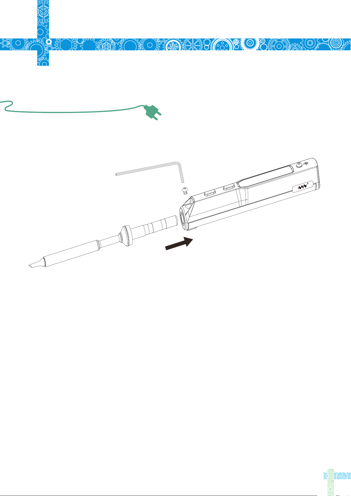
4.1 TS100 Installation
Operation
1. Loosen the tip setscrew, insert the soldering tip connector and
tighten the screw;
2. Connect the ground wire to the ground wire setscrew ;
3. Connect the DC connector to TS100, connect the power cord and turn
on the power accordingly.
Note: If the screen displays "sen-errwhen it’s plugged, means the soldering iron tip is not properly
fixed, please re-install it properly.
4.2 Default Settings
Default temperature unit
"
℃
Default temperature
Sleep mode temperature
Adjustable temperature range
300℃(Default)
200℃(Default)
100℃~400℃(Max)
6
Page 9
4
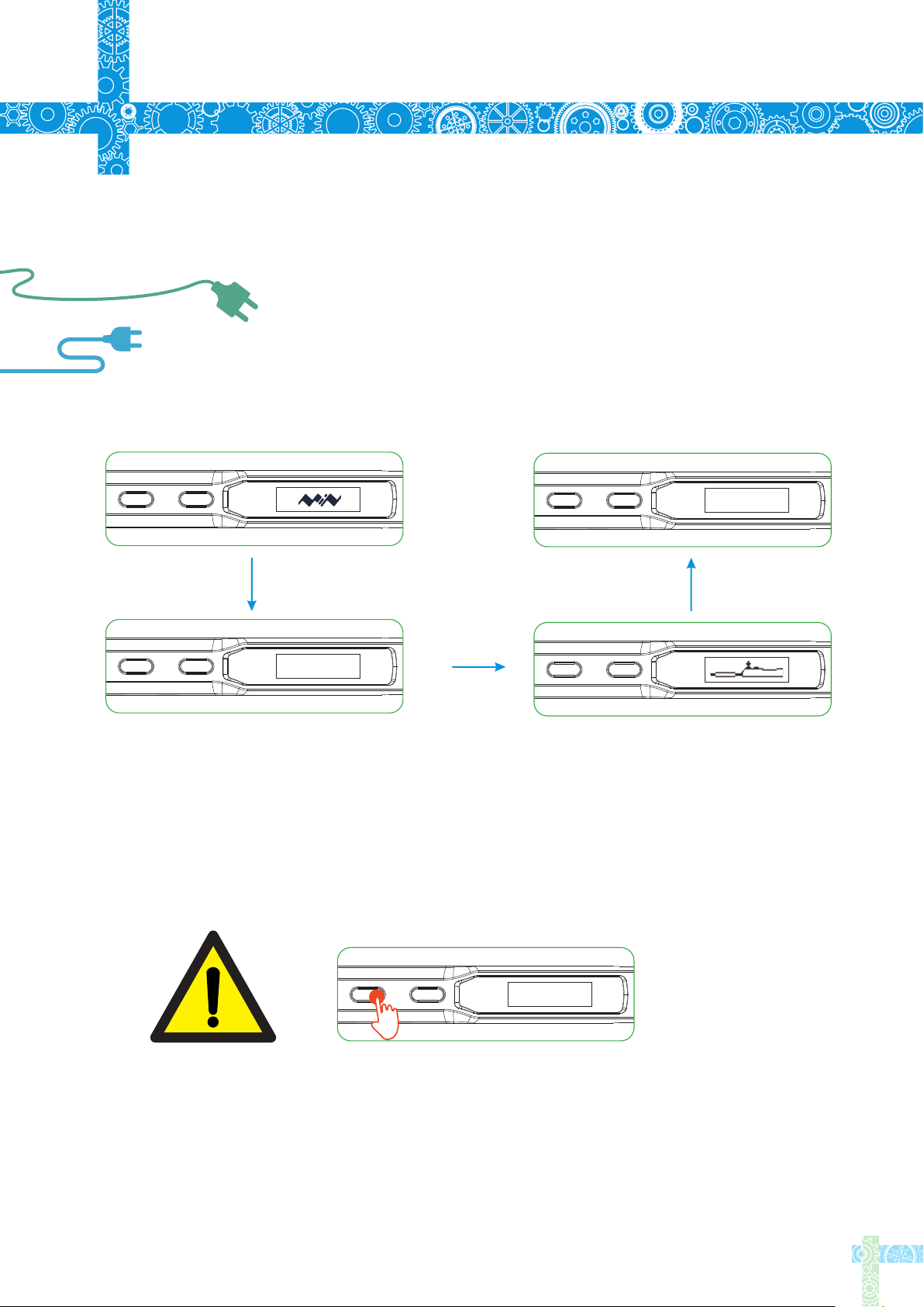
4.3 Basic Control
4.3.1 Screen Display
Operation
Press
.
Ver2 01
When plugged into DC12-24V power adaptor ,TS100 will display its logo,
Version number and its standby screen in sequence.
DFU1.0
When plugging into DC 12-24V power adaport ,pressing Button A at the sametime
will enter DFU mode,"DFU1.0" will appear on OLED screen .
To exit DFU mode: unplug and plug in the device again without pressing
any button ,then it will enter standby mode.
7
Page 10

4
4.3 Basic Control
4.3.2 Automatic Calibration
Operation
Press
Press Button B in standby mode to enter the thermometer mode
In thermometer mode, press 2 buttons at the same
time to enter the calibration mode
V
Cal_V
Display shows when calibration is succedd.
24℃
Cal_X
Display shows when calibration failed
24℃
Long press any button to exit thermometer mode
Note: Calibration shall be done when TS100 in room temperature
8
Page 11

4
4.3 Basic Control
4.3.3 Heating up
Operation
Press
When pressing Button A in standby mode,TS100 will heat up
to preset temperature
300℃
When OLED displays as picture, means it’s ready for soldering
300℃
In operation mode, holding both buttons for 3 senconds will return to standby mode
9
Page 12

4
4.3 Basic Control
4.3.4 Temperature Adjustment
Operation
300℃
In standby mode, press Button A will enter
preset temperature
246℃200℃
Release Button A when display reads the
expected temperature, and TS100 will
automatically adjust to it.
300℃
Temperature down: In temperature adjusting
mode, hold Button A for at least 2 seconds,
until display reads the temperature you want.
300℃
Temperature up: In temperature adjusting
mode, hold Button B for at least 2 seconds,
300℃
Release Button B when display reads the
expected temperature, and TS100 will
automatically adjust to it.
until display reads the temperature you want.
10
Page 13

4
4.3 Basic Control
4.3.4 Temperature Adjustment
Operation
400℃
Note: When screen displays arrow pointing to left or right (◀or▶)
which means the adjustment has already reached its upper/lower
limit temperature, settings will not be saved when power is off
Remark: Maximum temperature: 400℃
Minimum temperature:100℃
298℃
When TS100 temperature stabilizes for 60 seconds,it will automaticall yenter feedback mode,
100℃
temperature status will feedback every 5-8 seconds
The last digit on the right end of the display shown as below
Arrows up-heating arrows down-cooling
horizontal lines- temperature
stabilizeb
11
Page 14

4
4.3 Basic Control
4.3.5 Sleep Mode
Operation
200℃
In operation mode, when leaving TS100 for more than 180
seconds( 3 minutes in Default) will trigger the sleep mode,
and temperature will automactically adjust to preset sleep
temperature.
300℃
When working, TS100 will restart to operation mode and temperature
will automatically heat up to preset temperauture(300°C in Default).
Press
In sleep mode, if it’s not being operated for longer than the IDLE_TIME
setting, TS100 will then enter the standby mode.
Note:IDLE_TIME can be adjusted( 6 minutes in Default).(Preset minimum
IDLE time: 5 minutes)
12
Page 15

4
4.4 System Parameters
Operation
ParameterExplanationDefault
T_Standby
T_Work
Wait_Time
Idle_Time
T_Step
Standby mode temerature
Operating temperature
Time from operation mode
to sleep mode
Time from sleep mode
to standby mode
When preset "1",each step
will progress in 1,2,5,25;
when preset 2-25, each step
will progress according to
settings
200℃
300℃
180
seconds
360
seconds
10
Adjustable
range
100℃~400℃
100℃~400℃
60~9999
seconds
300~9999
seconds
5-25
Turn_Off_v
TempShowFlag
ZeroP_Ad
When operation voltage is
lower than default voltage
TS100 will return to stadby
mode
Temperature unit selection
Temperature calibration
parameter, TS100 automatical
adjustment
Notice: Preset parameter(s) will be updated to TS100 after saved.
10V
℃
9-12V
0 ℃,1 is ℉is
No manual
setting required
13
Page 16
5
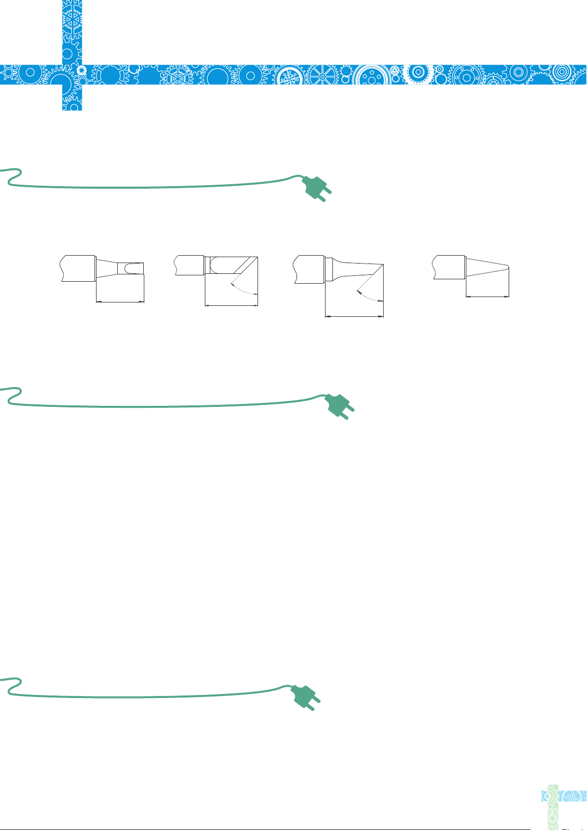
Soldering Iron Tip
5.1 Changing Soldering Tips
1.Unplug TS100 before changing.
2.Loosen the tip setscrew.
3.Pull out the tip, replace with another one.
4.Tighten the screw.
Note: When TS100 displays "sen-err", it means the soldering
iron tip is not installed properly.
14
Page 17
Soldering Iron Tip
5
5.2 Choosing Soldering Iron Tips
Note: Choosing the right tips will help you to work more efficient
4
5
°
10.0
15.0
11.5
4
5
°
10.0
TS-D24TS-BC2TS-KTS-B2
5.3 Soldering Iron Tip Maintenance
(1) Before switching off, wipe the tip’s soldering side with some solder.
(2) Do not leave the tip in high temperature for long time, which may causeit burn out.
(3) Do not push too hard while soldering, which will damage the tip.
(4) Do not use rough material or files to clean the tip.
(5) If the tip surface is oxidized and makes it hard to apply solder on it, you may use
600~800 grit sandpaper to wipe the tip with Ethanol or Isopropyl alcohol, heat
up to 200℃ and apply solder immdeiately to avoid it oxidize again.
(6) Do not use Flux that contains high chlorine or acid, use only resin based flux.
5.4 Soldering Iron Tip Lifespan
Soldering iron tips lifespan is related to its maintenance (refer to 5.3)and use intensity.
15
Page 18
6
Trouble Shooting Guide
Problem 1:No Display
Problem 2:Every time when installing
a new tip, the temperature status display
random numbers
Problem 3:Soldering iron restart
automatically
Check:If the cable is broken
Check:Is there any data in USB mode
Check:If the screen needs to be replaced
Means the machine is checking status,which is
normal
Check 1:Is it properly plugged into the power source?
Check 2:Is the voltage too low?
(need to be set up in the config file)
Problem 4:Soldering iron is heating up
and cooling down simultaneously
Problem 5:OLED shows "Warning!"
Check 1:Is the tip first time in use?
Check 2:Is the power cord in loose or defective contact?
Check 3:Is the tip overheating?
Set the temperature in appropriate level
Check 4:Is the soldering iron clean?
refer to "Soldering iron tip maintenance"
Check 1:Is the TS100 overheating?
Is TS100 temperature higher than the maximun
operation temperature
When temperature is lower than maximum operation
temperature, the warning sign will disappear and it will
return to operation mode
16
Page 19

6
Trouble Shooting Guide
Problem 6:OLED displays"High-Vt"
Problem 7:OLED displays "Sen-err"
Problem 8: The tip doesn’t stick to the solder
Check:Is the voltage too high?(over 24V)
Check 1:Is the soldering iron installed propely?
Check 2:If check 1 passes, then replace the
soldering iron tip
1.Tip temperature is over 400℃
2.The soldering side of the tip is not applied
with solder properly
3.Lack of flux during operation
4.Rub the tip against dry or high sulfur sponge
or fabric
5.Tip touched organic material like plastic,silicone
oil or other chemicals
Problem 9:TS100 return to standby mode
during operation
6.Using impure solder or solder that contains low
proportion of tin
Checl:Is the voltage lower than default(10V)
Wait until voltage recovers , it could work
normally when the voltage is over 10V
17
Page 20
Technical Support
7
7.1 Standard service
1 year of warranty will be provided for one year, if the damage was not caused by false
manipulation by the user.Plesae contact your retailer for warranty detail
Tips are consumables, once it’s used, no replacement will be provided.
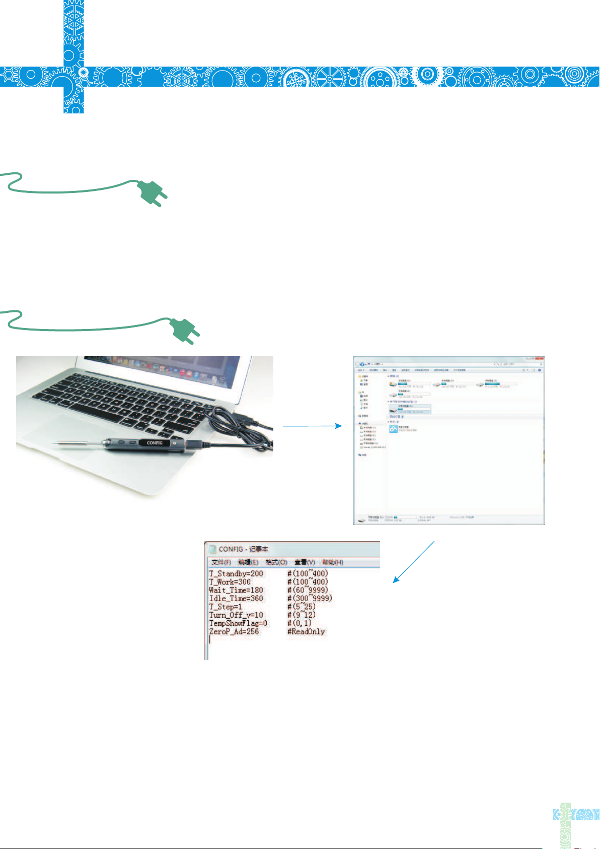
7.2 Default Parameter Setting
Connect TS100 to your PC with USB data cord, OLED will display "CONFIG"
and means it's in setting mode. Open config.txt file from the USB drive, set the
default parameters.
18
Page 21
7
Technical Support
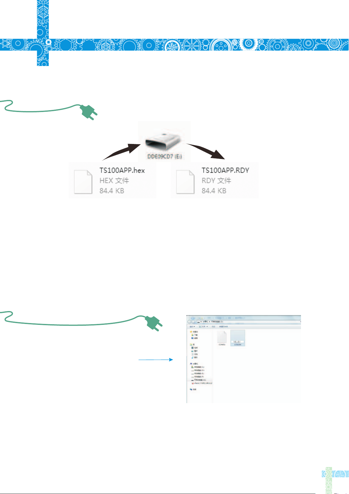
7.3 Firmware Update
1.Visit www.miniware.com.cn and download the latest TS100 firmware to your PC.
2.Connect TS100 to your PC with USB data cord,meanwhile,press TS100’s Button A
to enter DFU mode once a “DFU1.0” notice appears on the screen. A virtual disk with
8 serial numbers will appear on your PC.
3.Copy the hex firmware to the root directory of that disk. When the extension of the
firmware changes from “hex” to “rdy”, disconnect USB and the firmware is upgraded.
7.4 Changing Boot Up Screen
Create your own 96*16 pixel
image save as BMP in single
color bitmap
Copy the file to soldering iron’s USB
drive, change file name to "LOGOIN"
Note:When the "LOGOIN.BMP" exists in the USB drive, the boot up logo will be
using the file, if the file doesn’t exist, it will be using the default logo instead
19
Page 22
8
8.1 Disposal
Legal Statements
Do not dispose this product with domestic waste
Handling and recycle:Disposal of the product shall be
manipulated according to laws and regulations in your
area.
8.2 Statement of Fulfilling FCC Standard
This device fulfills part 15 of the FCC regulations Device must fulfill below 2
conditions:
(1) Device must not generate interference
(2) Device must be able to resist any interferences
on it, including interferences that could cause dangerous
manipulation
8.3 Statement of Fulfilling CE Standard
This is a trademark of Europe Union
This product with CE logo on it fulfills related
Euro Union laws and regulations
20
 Loading...