

Page 1
Online Edition for Part no. 01402917368 - © 10/12 BMW AG
OWNER'S MANUAL
MINI COUNTRYMAN
MINI PACEMAN
Contents
A - Z
Page 2

Cooper
Online Edition for Part no. 01402917368 - © 10/12 BMW AG
Cooper S
Cooper S ALL4
John Cooper
Works
Congratulations on your new MINI
This Owner's Manual should be considered a permanent part of
this vehicle. It should stay with the vehicle when sold to provide
the next owner with important operating, safety and maintenance information.
We wish you an enjoyable driving experience.
Page 3

© 2012 Bayerische Motoren Werke
Online Edition for Part no. 01402917368 - © 10/12 BMW AG
Aktiengesellschaft
Munich, Germany
Reprinting, including excerpts, only with the
written consent of BMW AG, Munich.
US English X/12, 11 12 500
Printed on environmentally friendly paper,
bleached without chlorine, suitable for recycling.
Page 4

Contents
Online Edition for Part no. 01402917368 - © 10/12 BMW AG
The fastest way to find information on a particular topic or item is by using the index, refer to
page 260.
4 Notes
7 Reporting safety defects
AT A GLANCE 9
10 Cockpit
16 Onboard computer
20 Letters and numbers
21 Voice activation system
CONTROLS 25
26 Opening and closing
38 Adjustments
46 Transporting children safely
50 Driving
60 Controls overview
71 Technology for driving comfort and safety
84 Lamps
88 Climate
93 Practical interior accessories
COMMUNICATIONS 163
164 Hands-free device Bluetooth
174 Mobile phone preparation Bluetooth
187 Office
195 MINI Connected
MOBILITY 199
200 Refueling
203 Wheels and tires
214 Engine compartment
218 Maintenance
220 Care
224 Replacing components
236 Giving and receiving assistance
REFERENCE 243
244 Technical data
252 Short commands for the voice activation
system
260 Everything from A to Z
DRIVING TIPS 103
104 Things to remember when driving
NAVIGATION 117
118 Navigation system
120 Destination entry
129 Route guidance
137 What to do if…
Entertainment 139
140 On/off and tone
143 Radio
151 CD player
153 External devices
Page 5

Notes
Online Edition for Part no. 01402917368 - © 10/12 BMW AG
Notes
Using this Owner's
Manual
We have tried to make all the information in this
Owner's Manual easy to find. The fastest way to
find specific topics is to refer to the detailed
index at the back of the manual. If you wish to
gain an initial overview of your vehicle, you will
find this in the first chapter.
Should you wish to sell your MINI at some time in
the future, remember to hand over this Owner's
Manual to the new owner; it is an important part
of the vehicle.
Additional sources of information
Should you have any other questions, your MINI
dealer will be glad to advise you at any time.
You can find more information about the MINI,
for example on its technology, on the Internet at
www.MINI.com.
Symbols used
Indicates precautions that must be followed precisely in order to avoid the pos-
sibility of personal injury and serious damage to
the vehicle.<
Indicates information that will assist you in
gaining the optimum benefit from your
vehicle and enable you to care more effectively
for your vehicle.<
Refers to measures that can be taken to
help protect the environment.<
< Marks the end of a specific item of informa-
tion.
"..." Identifies Control Display texts used to
select individual functions.
{...} Verbal instructions to use with the voice
activation system.
{{...}} Identifies the answers generated by the
voice activation system.
Symbols on vehicle components
Indicates that you should consult the relevant section of this Owner's Manual for
information on a particular part or assembly.
Vehicle equipment
The manufacturer of your MINI is the Bayerische
Motoren Werke Aktiengesellschaft, BMW AG.
This Owner's Manual describes all models as well
as all production, country and special equipment that is offered in the model range. Equipment is also described that is not available
because of, for example, selected options or
country version. This also applies to safety
related functions and systems. For equipment
and models that are not described in this
Owner's Manual, please see the supplementary
Owner's Manuals that are provided.
Status of this Owner's
Manual at time of
printing
The high level of safety and quality of the MINI
vehicles is ensured through continuous development. In rare cases, there may be differences
between the description and the vehicle.
For your safety
Maintenance and repair
Advanced technology, e.g. the use of
modern materials and high-performance
electronics, requires specially adapted mainte-
4
Page 6

Notes
Online Edition for Part no. 01402917368 - © 10/12 BMW AG
nance and repair methods. Therefore, have the
necessary work on your MINI only carried out by
a MINI dealer or a workshop that has specially
trained personnel working in accordance with
the specifications of the MINI manufacturer. If
this work is not carried out properly, there is a
danger of subsequent damage and related
safety hazards.<
Parts and accessories
For your own safety, use genuine parts
and accessories approved by the manu-
facturer of the MINI.
When you purchase accessories tested and
approved by the manufacturer of the MINI and
Original MINI Parts, you simultaneously acquire
the assurance that they have been thoroughly
tested by the manufacturer of the MINI to
ensure optimum performance when installed on
your vehicle.
The manufacturer of the MINI warrants these
parts to be free from defects in material and
workmanship.
The manufacturer of the MINI will not accept any
liability for damage resulting from installation of
parts and accessories not approved by the manufacturer of the MINI.
The manufacturer of the MINI cannot test every
product made by other manufacturers to verify
if it can be used on a MINI safely and without risk
to either the vehicle, its operation, or its occupants.
Original MINI Parts, MINI Accessories and other
products approved by the manufacturer of the
MINI, together with professional advice on using
these items, are available from all MINI dealers.
Installation and operation of accessories that
have not been approved by the manufacturer of
your MINI, such as alarms, radios, amplifiers,
radar detectors, wheels, suspension components, brake dust shields, telephones, including
operation of any mobile phone from within the
vehicle without using an externally mounted
antenna, or transceiver equipment, for instance,
CBs, walkie-talkies, ham radios or similar acces-
sories, may cause extensive damage to the vehicle, compromise its safety, interfere with the
vehicle's electrical sys te m o r a ff ec t t he va lidi ty of
the MINI Limited Warranty. See your MINI dealer
for additional information.<
Maintenance, replacement, or repair of
the emission control devices and systems
may be performed by any automotive repair
establishment or individual using any certified
automotive part.<
California Proposition 65 Warning
California law requires us to issue the following
warning:
Engine exhaust and a wide variety of
automobile components and parts,
including components found in the interior furnishings in a vehicle, contain or emit chemicals
known to the State of California to cause cancer
and birth defects and reproductive harm. In
addition, certain fluids contained in vehicles and
certain products of component wear contain or
emit chemicals known to the State of California
to cause cancer and birth defects or other reproductive harm.
Battery posts, terminals and related accessories
contain lead and lead compounds. Wash your
hands after handling.
Used engine oil contains chemicals that have
caused cancer in laboratory animals. Always
protect your skin by washing thoroughly with
soap and water.<
Service and warranty
We recommend that you read this publication
thoroughly.
Your MINI is covered by the following warranties:
> New Vehicle Limited Warranty
> Rust Perforation Limited Warranty
> Federal Emissions System Defect Warranty
5
Page 7

Notes
Online Edition for Part no. 01402917368 - © 10/12 BMW AG
> Federal Emissions Performance Warranty
> California Emission Control System Limited
Warranty
Detailed information about these warranties is
listed in the Service and Warranty Information
Booklet for US models or in the Warranty and
Service Guide Booklet for Canadian models.
Your vehicle has been specifically adapted and
designed to meet the particular operating conditions and homologation requirements in your
country and continental region in order to
deliver the full driving pleasure while the vehicle
is operated under those conditions. If you wish
to operate your vehicle in another country or
region, you may be required to adapt your vehicle to meet different prevailing operating conditions and registration requirements. You should
also be aware of any applicable warranty limitations or exclusions for such country or region. In
such a case, please contact Customer Relations
for further information.
Maintenance
Maintain the vehicle regularly to sustain road
safety, operational reliability and the New Vehicle Limited Warranty.
Specifications for required maintenance measures:
> MINI Maintenance System
> Service and Warranty Information Booklet
for US models
> Warranty and Service Guide Booklet for
Canadian models
If the vehicle is not maintained according to
these specifications, this could result in serious
damage to the vehicle. Such damage is not covered by the MINI New Vehicle Limited Warranty.
Data memory
A variety of electronic components in your vehicle include data storage devices, which store
technical information on the condition of your
vehicle, events and errors, either temporarily or
permanently. In general, this technical information documents the condition of a component, a
module, a system or the surroundings:
> Operating conditions of system compo-
nents, e.g., fill levels.
> Status messages regarding the vehicle and
of its individual components, such as wheel
rpm/vehicle speed, response delay, lateral
acceleration.
> Malfunctions and defects in the major sys-
tem components, such as the lights and
brakes.
> Responses of the vehicle in special driving
situations, such as the deployment of an airbag, the utilization of stability control systems.
> Environmental conditions, such as tempera-
ture.
These data are exclusively of a technical nature
and are used for the detection and correction of
errors, as well as the optimization of vehicle
functions. Motion profiles of traveled routes can
not be deduced from these data. If services are
required, such as repair services, service processes, warranty claims and quality assurance,
then this technical information can be read out
by employees of service departments, including
the manufacturer, from the event and error data
storage devices by using special diagnostic
equipment. There, if necessary, you will receive
further information. After remedying an error,
the information in the error memory is deleted
or progressively overwritten.
When using the vehicle, situations are conceivable in which this technical data, in conjunction
with other information, such as accident reports,
vehicle damage, witness statements, etc. - possibly with the assistance of an expert - could be
traced to particular individuals. Additional functions that are agreed upon contractually with
the customer, such as vehicle tracking in case of
emergency, permit the transmission of certain
vehicle data from the vehicle.
6
Page 8

Notes
Online Edition for Part no. 01402917368 - © 10/12 BMW AG
Event data recorder EDR
This vehicle is equipped with an event data
recorder EDR. The main purpose of an EDR is to
record, in certain crash or crash-like situations
such as an air bag deployment or collision with a
road obstacle, data that will assist in understanding how a vehicle's systems performed.
The EDR is designed to record data related to
vehicle dynamics and safety systems for a short
period of time, typically 30 seconds or less.
The EDR in this vehicle is designed to record data
such as:
> How various systems in your vehicle were
operating.
> Whether or not the driver and passenger
safety belts were fastened.
> How far, if at all, the driver was depressing
the accelerator and/or brake pedal.
> How fast the vehicle was traveling.
These data can help provide a better understanding of the circumstances in which crashes
and injuries occur.
EDR data are recorded by your vehicle only if a
nontrivial crash situation occurs; no data are
recorded by the EDR under normal driving conditions and no personal data, e.g., name, gender, age, and crash location, are recorded.
However, other parties, such as law enforcement, could combine the EDR data with the type
of personally identifying data routinely acquired
during a crash investigation.
Reading the data recorded by an EDR requires
special equipment and access to the vehicle or
the EDR. In addition to the vehicle manufacturer, other parties that have the special equipment such as law enforcement, can read the
information if they have access to the vehicle or
the EDR.
Reporting safety defects
For US customers
The following applies only to vehicles owned
and operated in the US.
If you believe that your vehicle has a defect that
could cause a crash or could cause injury or
death, you should immediately inform the
National Highway Traffic Safety Administration,
NHTSA, in addition to notifying MINI of
North America, LLC, P.O. Box 1227,
Westwood, New Jersey 07675-1227,
Telephone 1-800-831-1117.
If NHTSA receives similar complaints, it may
open an investigation, and if it finds that a safety
defect exists in a group of vehicles, it may order
a recall and remedy campaign. However, NHTSA
cannot become involved in individual problems
between you, your dealer, or MINI of North
America, LLC.
To contact NHTSA, you may call the Vehicle
Safety Hotline toll-free at 1-888-327-4236
(TTY: 1-800-424-9153); go to http://www.safercar.gov; or write to: Administrator, NHTSA, 400
Seventh Street, SW., Washington, DC 20590. You
can also obtain other information about motor
vehicle safety from http://www.safercar.gov
For Canadian customers
Canadian customers who wish to report a
safety-related defect to Transport Canada,
Defect Investigations and Recalls, may telephone the toll-free hotline 1-800-333-0510.
You can also obtain other information about
motor vehicle safety from http://www.tc.gc.ca/
roadsafety.
7
Page 9
Watch Me.
Online Edition for Part no. 01402917368 - © 10/12 BMW AG
Page 10

AT A GLANCE
Online Edition for Part no. 01402917368 - © 10/12 BMW AG
CONTROLS
DRIVING TIPS
NAVIGATION
Entertainment
COMMUNICATIONS
MOBILITY
REFERENCE
Page 11
AT A GLANCE Cockpit
Online Edition for Part no. 01402917368 - © 10/12 BMW AG
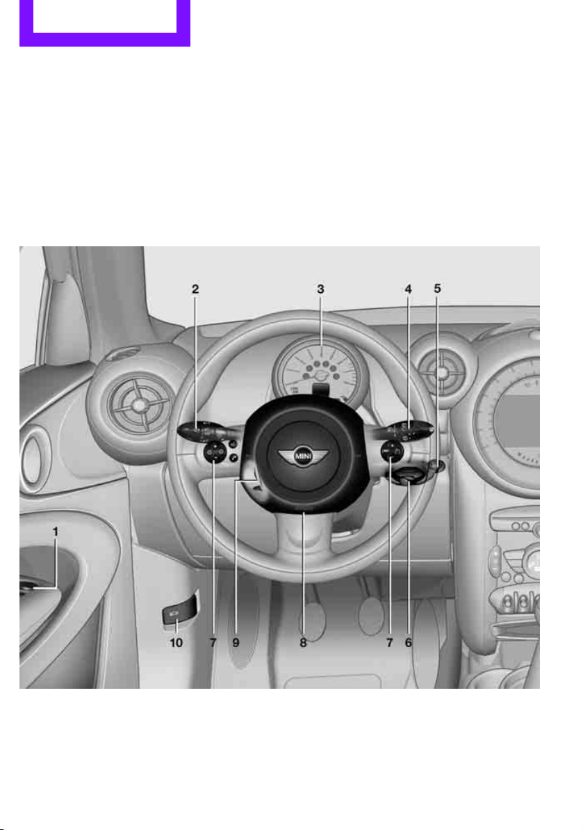
Cockpit
Vehicle equipment
In this chapter, all production, country, and
optional equipment that is offered in the model
Around the steering wheel
range is described. Equipment is also described
that is not available because of, for example,
selected options or country version. This also
applies to safety related functions and systems.
10
Page 12
Cockpit AT A GLANCE
Online Edition for Part no. 01402917368 - © 10/12 BMW AG
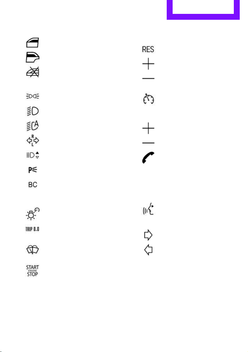
1 Adjusting the exterior mirrors in and out 44
Power windows, front 36
MINI Countryman: power windows,
rear 36
MINI Countryman: safety switch for
power windows in rear passenger
compartment 37
2
Parking lamps 84
Low beams 84
Automatic headlamp control 84
Adaptive Light Control 85
Turn signals 55
High beams 86
Headlamp flasher 55
Roadside parking lamps 86
Computer 61
3 Tachometer 12
Instrument lighting 86
Resetting the trip odometer 60
4
Wiper system 55
7 Buttons on steering wheel,
right
Resuming cruise control 58
Storing speed and accelerating or
decelerating
Activating/deactivating cruise
control 58
left side
Increasing or reducing volume
Telephone
Press: accepting and ending a call,
starting dialing of selected phone
number and redialing if no phone
number is selected
Microphone in the roofliner on the
driver's side
Activating/deactivating voice activation system 21
Microphone in the roofliner on the
driver's side
Changing the radio station
Selecting a music track
Scrolling through the redial list
5
Switching the ignition on/off and
starting/stopping the engine 50
6 Ignition lock 50
8 Horn: the entire surface
9 Adjusting the steering wheel 45
10 Releasing the hood 215
11
Page 13
AT A GLANCE Cockpit
Online Edition for Part no. 01402917368 - © 10/12 BMW AG
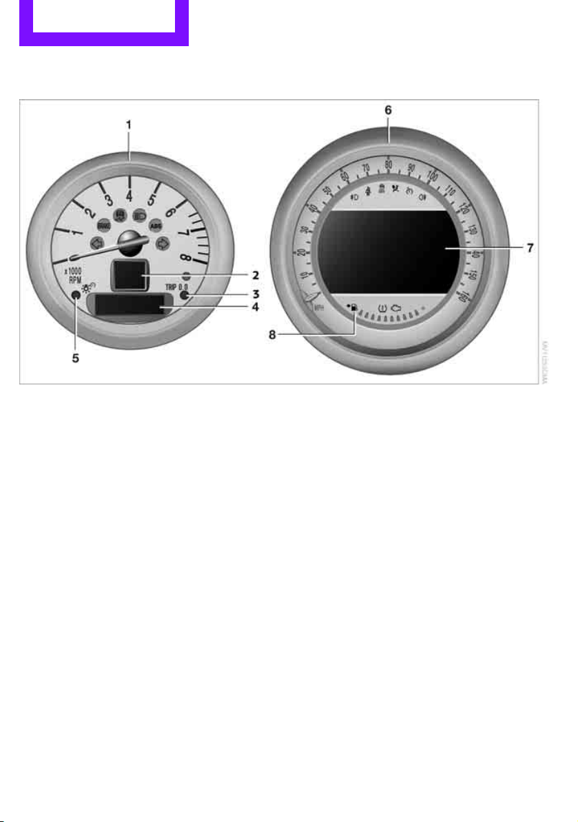
Displays
1 Tachometer 60
with indicator and warning lamps 13
2 Display for
> Current vehicle speed 60
> Indicator and warning lamps 13
3 Resetting the trip odometer 60
4 Display for
> Position of automatic transmission 52
> Computer 61
> Date of next scheduled service, and
remaining distance to be driven 64
> Odometer and trip odometer 60
> Settings and information 62
> Personal Profile settings 26
5 Instrument lighting 86
6 Speedometer
with indicator and warning lamps 13
7 Control Display 17
8 Fuel gauge 60
12
Page 14
Indicator and warning
Online Edition for Part no. 01402917368 - © 10/12 BMW AG
lamps
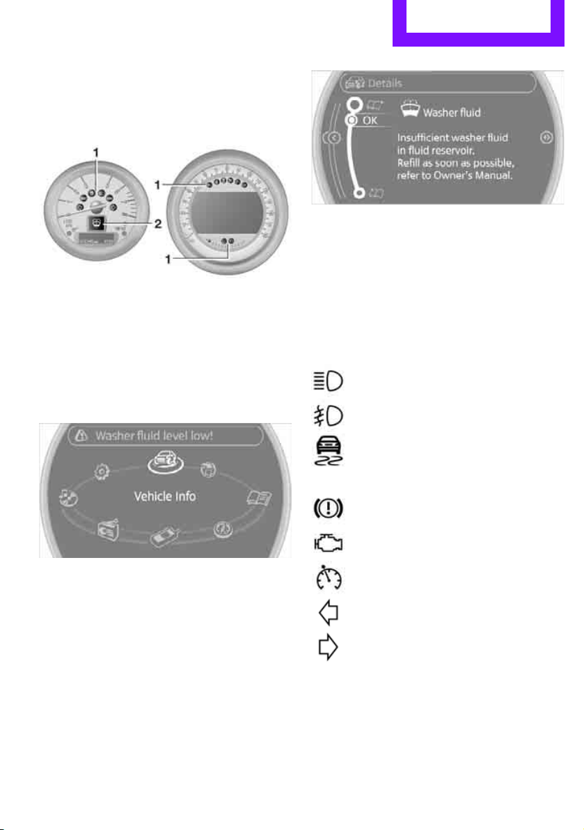
The concept
Indicator and warning lamps can light up in various combinations and colors in indicator area 1
or 2.
Some lamps will be tested for proper functioning
when the engine is started or the ignition is
switched on and will therefore light up briefly.
Cockpit AT A GLANCE
You can call up more information, e.g. on the
cause of a malfunction and on how to respond,
via Check Control, page 67.
In urgent cases, this information will be shown
as soon as the corresponding lamp lights up.
Indicator lamps without text messages
The following indicator lamps in display area 1
indicate certain functions:
High beams/headlamp flasher 86
Explanatory text messages
Text messages at the upper edge of the Control
Display explain the meaning of the displayed
indicator and warning lamps.
Front fog lamps 86
Lamp flashes:
DSC or DTC is regulating the drive
forces in order to maintain driving
stability 72
Parking brake applied 52
Engine malfunction with adverse effect
on exhaust emissions 219
Cruise control 58
Turn signals 55
13
Page 15
AT A GLANCE Cockpit
Online Edition for Part no. 01402917368 - © 10/12 BMW AG
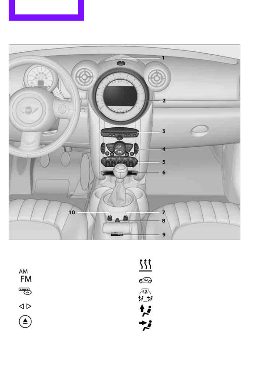
Around the center console
1 Hazard warning flashers
2 Speedometer 12
3 Radio/CD 143
Selecting waveband
Changing the audio source
Changing the radio station or track
Ejecting CD
4 Air conditioner or automatic climate
14
control 88
Temperature
Recirculated-air mode
Air distribution for air conditioner
Air distribution to the windshield
Air distribution to the upper body
area
Page 16
Cockpit AT A GLANCE
Online Edition for Part no. 01402917368 - © 10/12 BMW AG
Air distribution to the footwell
Automatic air distribution and flow
rate
Maximum cooling
Cooling function
Defrosting windows
Rear window defroster
Windshield heating
Air flow rate
5 Switches in the center console
Seat heating 42
Central locking system, inside 30
Front fog lamps 86
6 Storage compartment
7 Changing to a different menu on the Control
Display 18
8 MINI joystick 16
Move in four directions, turn or press
9 USB audio interface 154
10 Accessing the main menu on the Control
Display 17
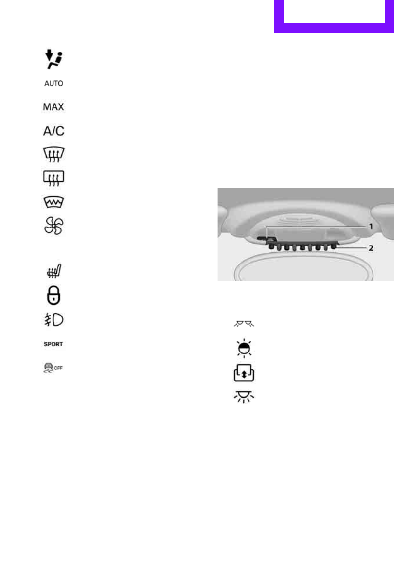
Around the headliner
1 Indicator/warning lamp for front passenger
airbags 82
2
Reading lamps 87
Sport button 74
Driving stability control systems
Dynamic Stability Control DSC 72
Dynamic Traction Control
DTC 73
Ambient lighting 87
Glass roof, electric 35
Interior lamps 87
15
Page 17
AT A GLANCE Onboard computer
Online Edition for Part no. 01402917368 - © 10/12 BMW AG
Onboard computer
Vehicle equipment
In this chapter, all production, country, and
optional equipment that is offered in the model
range is described. Equipment is also described
that is not available because of, for example,
selected options or country version. This also
applies to safety related functions and systems.
The concept
The onboard computer integrates the functions
of a large number of switches. This allows these
functions to be operated from a single central
position. The following section provides an
introduction to basic menu navigation. The control of the individual functions is described in
connection with the relevant equipment.
Make entries only when traffic and road
conditions permit; otherwise, you may
endanger vehicle occupants and other road
users by being distracted.<
Overview of operating
elements
Controls
Control Display
Notes
> When cleaning the Control Display, follow
the care instructions.
> Do not place any objects in the area of the
Control Display; otherwise, the Control Display can be damaged.
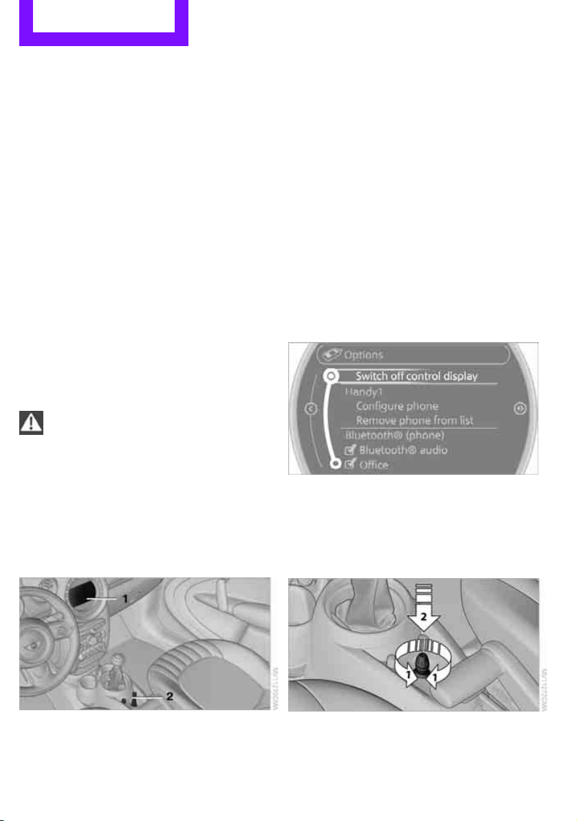
Switching Control Display off/on
1. Move the MINI joystick to the right repeat-
edly until the "Options" menu is displayed.
2. "Switch off control display"
To switch on, press the MINI joystick.
MINI joystick with buttons
Selecting menu items and carrying out settings.
1. Turning 1 and pressing 2.
1 Control Display
2 MINI joystick with buttons
16
Page 18
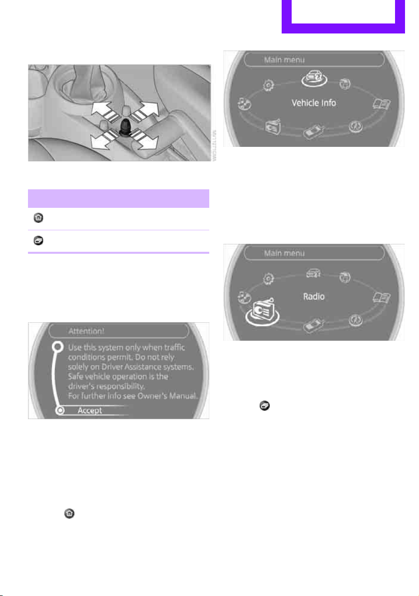
2. Tilting in four directions.
Online Edition for Part no. 01402917368 - © 10/12 BMW AG
Buttons on MINI joystick
Button Function
Accessing the main menu
Changing to another menu
Operating principle
As of radio readiness, the following message
appears on the Control Display:
Onboard computer AT A GLANCE
All functions of the onboard computer can be
accessed via the main menu.
Selecting a menu item
Menu items displayed in white can be selected.
1. Turn the MINI joystick until the desired
menu item is highlighted.
To hide the message:
Press the MINI joystick.
The main menu is displayed.
The message is automatically hidden after
approx. 10 seconds.
Opening the main menu
Press the button.
2. Press the MINI joystick.
A new menu is displayed or the function is executed.
Using the button on the MINI joystick:
Press the button.
Each time that the button is pressed, the menu
items of the main menu can be called up, one
after another.
Menu items in the Owner's Manual
In the Owner's Manual, the menu items that
should be selected are depicted in quotation
marks, e.g. "Settings".
17
Page 19
AT A GLANCE Onboard computer
Online Edition for Part no. 01402917368 - © 10/12 BMW AG
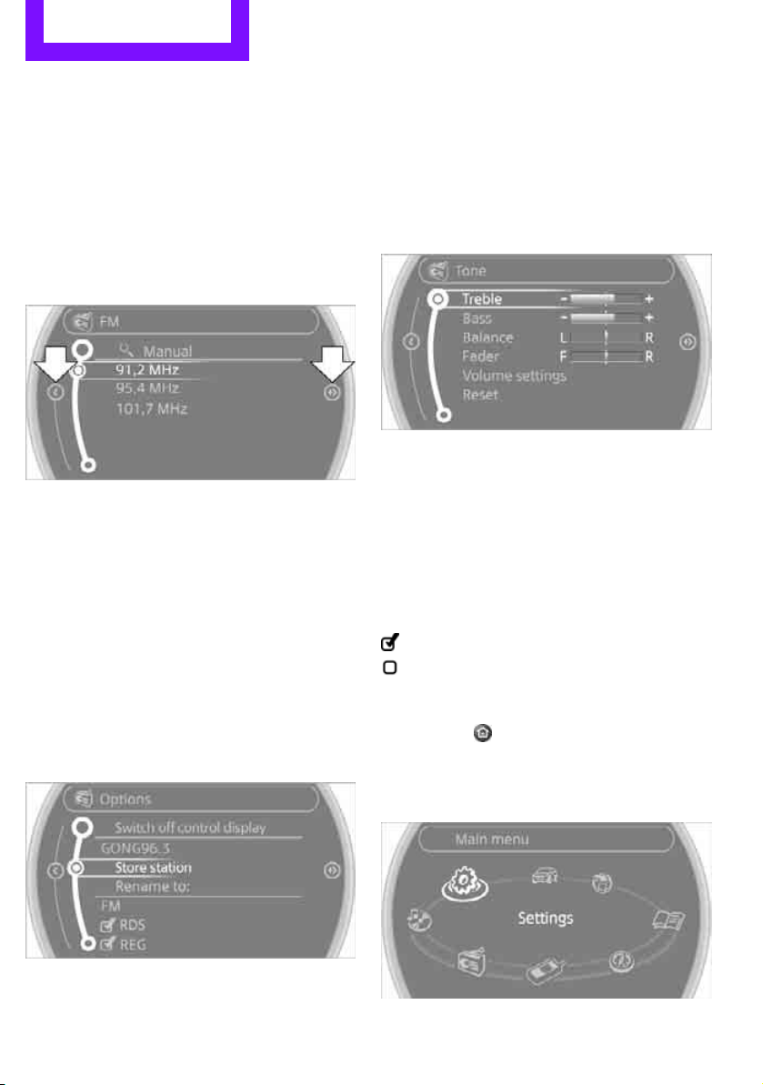
Changing between panels
After selecting a menu item, e.g. "Radio", a new
menu is displayed on a panel. The panels can
overlap.
> Move the MINI joystick to the left.
Current panel is closed and the previous
panel is displayed.
> Move the MINI joystick to the right.
The new panel is opened and placed on top.
Arrows pointing left or right indicate that additional panels can be accessed.
View of a menu that has been called up
In general, when a menu is called up, the panel
that was last selected in the menu is displayed.
To display the first panel of the menu:
Move the MINI joystick as often to the left as
necessary until the first panel is displayed.
> Screen settings.
> Control options for the selected menu.
Adjusting settings
1. Select a field.
2. Turn the MINI joystick until the desired set-
ting is displayed.
3. Press the MINI joystick to confirm the set-
ting.
Activating/deactivating functions
Some menu items are preceded by a check box.
It indicates whether the function is activated or
deactivated.
Selecting the menu item activates or deactivates
the function.
Function is activated.
Function is deactivated.
Opening the Options menu
Move the MINI joystick to the right repeatedly
until the "Options" menu is displayed.
The following is displayed in the "Options"
menu:
Example: setting the clock
1. Press the button.
2. Turn the MINI joystick until "Settings" is
18
The main menu is displayed.
selected, and press the MINI joystick.
Page 20
Onboard computer AT A GLANCE
Online Edition for Part no. 01402917368 - © 10/12 BMW AG
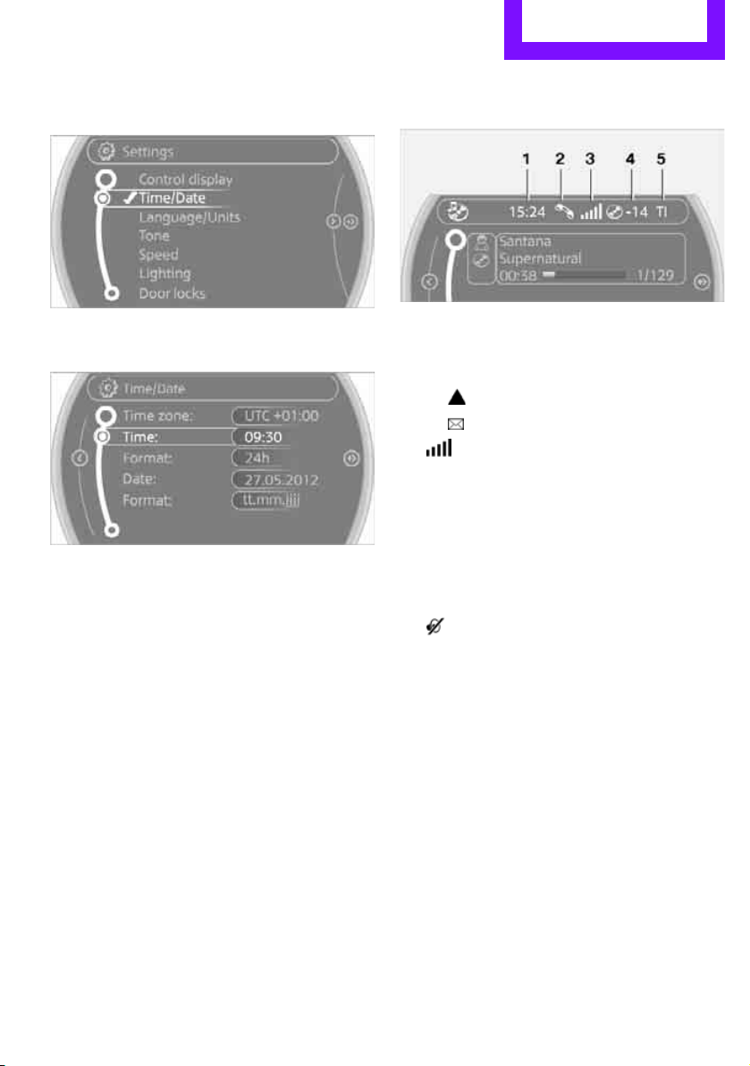
3. Turn the MINI joystick until "Time/Date" is
selected, and press the MINI joystick.
4. Turn the MINI joystick until "Time:" is
selected, and press the MINI joystick.
5. Turn the MINI joystick to set the hours and
press the MINI joystick.
6. Turn the MINI joystick to set the minutes and
press the MINI joystick.
Status information
1 Time
2 Telephone status
> Incoming, outgoing or missed call
> Roaming active
> Text message received
3 Reception strength of the wireless net-
work, depends on the mobile phone
4 Display for:
> Entertainment:
Radio, CD, external devices
> Telephone:
Name of the mobile phone paired with
the vehicle
5 Sound output is switched off or
display for traffic bulletins:
> "TI":
Traffic bulletins are switched on.
> No display:
Traffic bulletins are switched off.
Other displays:
Status information is temporarily hidden during
Check Control message displays or entries via
the voice activation system.
19
Page 21
AT A GLANCE Letters and numbers
Online Edition for Part no. 01402917368 - © 10/12 BMW AG
Letters and numbers
Vehicle equipment
In this chapter, all production, country, and
optional equipment that is offered in the model
range is described. Equipment is also described
that is not available because of, for example,
selected options or country version. This also
applies to safety related functions and systems.
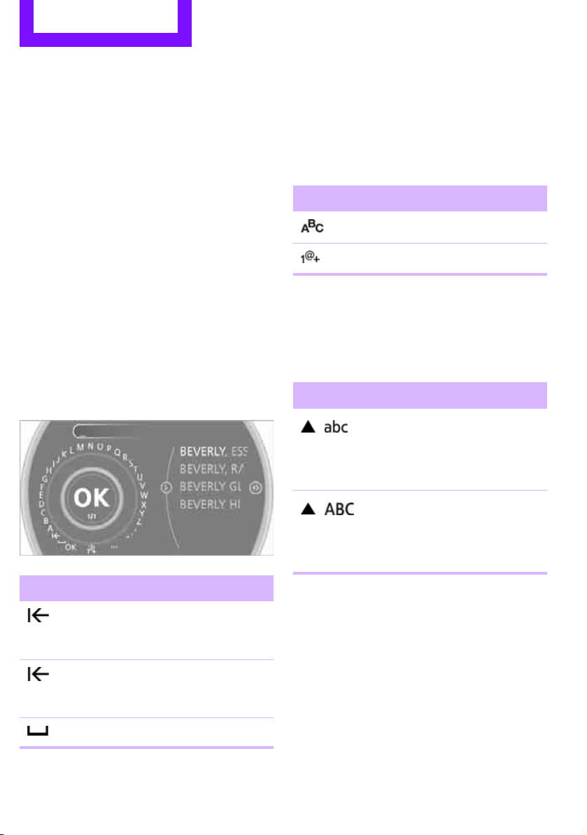
Entering letters and
numbers
1. Turn the MINI joystick: select the letters or
numbers.
2. Select additional letters or numbers if
needed.
3. "OK": confirm entry.
Switching between letters and numbers
Depending on the menu, you can switch
between entering letters and numbers:
Symbol Function
Entering letters
Entering numbers
Switching between uppercase and
lowercase letters
Depending on the menu, you can switch
between entering uppercase letters and lowercase letters:
Symbol Function
Move the MINI joystick forward: to switch from uppercase letters to lowercase letters
Move the MINI joystick forward: to switch from lowercase letters to uppercase letters
Symbol Function
Press the MINI joystick:
delete one letter or number
Press and hold the
MINI joystick: delete all letters or numbers
Enter a blank space
Wordmatch concept during navigation
Entry of names and addresses: the selection is
narrowed down every time a letter is entered
and letters may be added automatically.
Destination search: the entries are continuously
compared to the data stored in the vehicle.
> The only letters offered for entering
> Town/city names can be entered with the
20
addresses are those for which data are available.
spelling used in any of the languages available on the Control Display.
Page 22
Voice activation system AT A GLANCE
Online Edition for Part no. 01402917368 - © 10/12 BMW AG
Voice activation system
Vehicle equipment
In this chapter, all production, country, and
optional equipment that is offered in the model
range is described. Equipment is also described
that is not available because of, for example,
selected options or country version. This also
applies to safety related functions and systems.
The concept
> By using the voice activation system, most of
the functions that are displayed on the Control Display can be operated via voice commands. The system supports the entry process by means of announcements.
> Functions that can only be used while the
vehicle is not moving cannot be operated via
the voice activation system.
> The system includes a special microphone in
the roofliner on the driver's side.
Prerequisite
So that voice commands can be identified, set a
language on the Control Display that is supported by the voice activation system.
To set the language, see page 69.
Symbols in the Owner's Manual
{...} Say the specified commands word for
word.
{{...}} Identifies the answers generated by
the voice activation system.
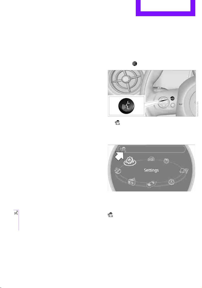
Saying commands
Activating voice activation system
1. Press the button on the steering wheel.
This symbol on the Control Display and
an acoustic signal indicate that the voice
activation system is ready to receive spoken
commands.
2. Say the command.
The command appears on the Control Display.
This symbol is displayed on the Control Display when you can enter additional commands.
If no further commands are possible, continue
by operating the item of equipment via the
onboard computer.
21
Page 23

AT A GLANCE Voice activation system
Online Edition for Part no. 01402917368 - © 10/12 BMW AG
Terminating or canceling voice
activation system
Press the button on the steering wheel
or
{Cancel}
Possible commands
Most menu items on the Control Display can be
spoken as commands.
The commands that are possible depend upon
which menu is currently shown on the Control
Display.
There are short commands for many functions.
Some list items, for example telephone book
listings, can also be selected using the voice activation system. In particular, say the list items
exactly as they are displayed in the respective
list.
Having the possible commands read
aloud
Having the possible commands read aloud:
{Voice commands}
For example if you have selected "CD" the system will read aloud the possible commands for
operating the CD player.
Carrying out functions through short
commands
Main menu functions can be executed immediately by short commands, almost regardless of
which menu item is selected, e.g., {Vehicle status}.
List of voice activation system short commands,
see page 252.
Help for the voice activation system
Calling up Help:
{Help}
Additional commands for Help:
> {Help with examples}: information about
the current operating options and the most
important commands for them are
announced.
> {Help with voice activation}: information
regarding the principles behind the voice
activation system is announced.
Using alternative commands
There are often a number of commands to run a
function, e.g.:
{Radio} or {Radio on}
Opening the main menu
{Main menu}
Example: playing a CD
Via the main menu
The commands of the menu items are spoken
aloud; they can also be selected using the MINI
joystick.
1. Switch on Entertainment sound output if
necessary.
2. Press the button on the steering wheel
3. {{C D and multimedia}}
4. {C D}
5. {C D track …}
6. {Track …}e.g. CD track 4.
Via short commands
The CD playback can also be started by a short
command.
1. Switch on Entertainment sound output if
necessary.
2. Press the button on the steering wheel.
3. {C D … track …} e.g. CD track 4.
22
Page 24
Voice activation system AT A GLANCE
Online Edition for Part no. 01402917368 - © 10/12 BMW AG
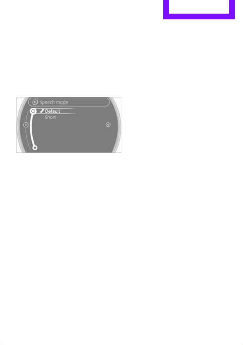
Setting the voice dialog
You can set whether the system uses the standard dialog or a short version.
With the short version of the spoken dialog, a
shortened version of the requests and responses
of the voice activation system are played aloud.
1. "Settings"
2. "Language/Units"
3. "Speech mode:"
4. Select a setting:
> "Default"
> "Short"
Notes
> Keep the doors, windows and glass roof
closed to prevent interference from outside
noise.
> Avoid ambient noise in the vehicle while
speaking.
For voice commands, bear in mind the following:
> Do not use the voice activation system to ini-
tiate an emergency call. In stressful situations, the voice and vocal pitch can change.
This can unnecessarily delay the establishment of a telephone connection.
> Pronounce the commands and digits
smoothly and at normal volume, avoiding
excessive emphases and pauses. The same
applies to spelling when entering a destination for navigation.
> Always speak the commands in the lan-
guage of the voice activation system.
> When selecting a radio station, use the stan-
dard pronunciation of the station name
{Select station} e.g. WPLJ
23
Page 25
Handle Me.
Online Edition for Part no. 01402917368 - © 10/12 BMW AG
Page 26

AT A GLANCE
Online Edition for Part no. 01402917368 - © 10/12 BMW AG
CONTROLS
DRIVING TIPS
NAVIGATION
Entertainment
COMMUNICATIONS
MOBILITY
REFERENCE
Page 27
CONTROLS Opening and closing
Online Edition for Part no. 01402917368 - © 10/12 BMW AG
Opening and closing
Vehicle equipment
In this chapter, all production, country, and
optional equipment that is offered in the model
range is described. Equipment is also described
that is not available because of, for example,
selected options or country version. This also
applies to safety related functions and systems.
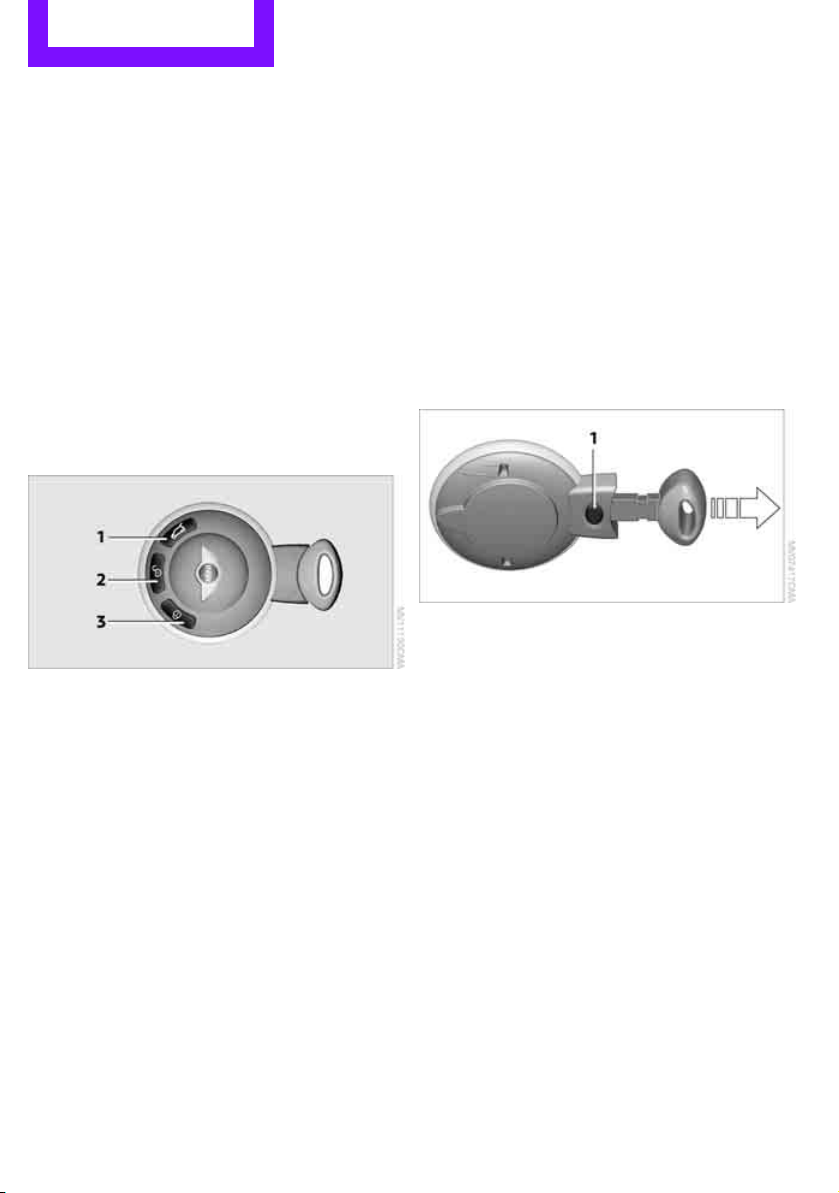
Keys/remote controls
Buttons on the remote control
1 Opening the tailgate
2 Unlocking
3 Locking
In addition, information about service requirements is stored in the remote control, refer to
Service data in the remote control, page 218.
New remote controls
Your MINI dealer can supply new remote controls as additional units or as replacements in the
event of loss.
Integrated key
Press button 1 to release the key.
The integrated key fits the following locks:
> Driver's door, page 29
Personal Profile
General information
Each remote control contains a rechargeable
battery that is recharged when it is in the ignition lock while the car is being driven. You
should therefore use each remote control at
least twice a year to maintain the charge status.
In vehicles equipped with Comfort Access, the
remote control contains a replaceable battery,
page 35.
If more than one remote control unit is used, the
settings called up and implemented depend on
which remote control is recognized when the
car is unlocked, refer to Personal Profile,
page 26.
The concept
The functions of your MINI can be set individually. By means of Personal Profiles, most of these
settings are stored for the remote control currently in use. When you unlock the car, the
remote control is recognized and the settings
stored for it are called up and implemented.
This means that your settings will be activated
for you, even if in the meantime your car was
used by someone else with another remote control and the corresponding settings.
Individual settings are stored for a maximum of
three remote controls.
26
Page 28

Opening and closing CONTROLS
Online Edition for Part no. 01402917368 - © 10/12 BMW AG
Personal Profile settings
For more information on specific settings, refer
to the specified pages.
> Response of the central locking system
when the car is being unlocked 27
> Automatic locking of the vehicle 30
> Triple turn signal activation 55
> Settings for the displays on the onboard
computer, in the speedometer and in the
tachometer:
> 12 h/24 h mode of the clock 66
> Date format 67
> Brightness of the Control Display 70
> Language on the Control Display 69
> Units of measure for fuel consumption,
distance covered/remaining distances
and temperature 64
> Light settings:
> Pathway lighting 85
> Daytime running lights 85
> Automatic climate control: activating/deac-
tivating the AUTO program, setting the temperature, air volume and air distribution 90
> Entertainment:
> Audio volume 141
> Tone control 141
Central locking system
The concept
The central locking system is ready for operation
whenever the driver's door is closed.
The system simultaneously engages and
releases the locks on the following:
> Doors
> Tailgate
> Fuel filler flap
Operating from outside
> Via the remote control
> Using the door lock
> In cars with Comfort Access, via the door
handles on the driver's and passenger's
sides
The anti-theft system is also operated at the
same time. It prevents the doors from being
unlocked using the lock buttons or door handles. The remote control can also be used to
switch the welcome lamps, the interior light, and
the ambient lighting on and off. The alarm sys-
is also activated or deactivated, page 32.
tem
Operating from inside
Switch/button for central locking system,
page 30.
In the event of a sufficiently severe accident, the
central locking system unlocks automatically. In
addition, the hazard warning flashers and interior lamps come on.
Opening and closing:
from outside
Persons or animals in a parked vehicle
could lock the doors from the inside. Take
the key with you when you leave the vehicle so
that the vehicle can be opened from the outside.<
Using the remote control
Unlocking
Press the button.
The welcome lamps and interior lamps come on.
Unlocking mode
You can also set which parts of the car are
unlocked. The setting is stored for the remote
control in use.
27
Page 29
CONTROLS Opening and closing
Online Edition for Part no. 01402917368 - © 10/12 BMW AG
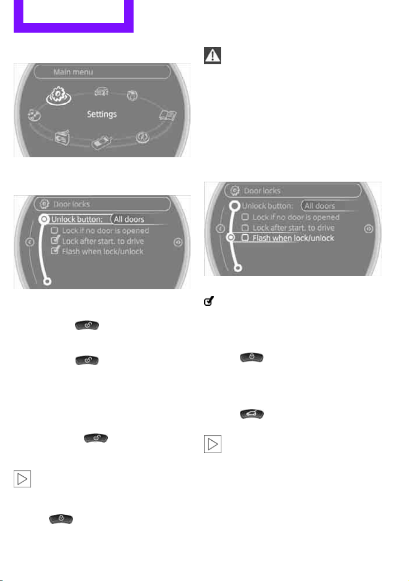
1. "Settings"
2. "Door locks"
3. "Unlock button"
4. Select a menu item:
> "All doors"
Press the button once to unlock
the entire vehicle.
> "Driver's door only"
Press the button once to unlock
only the driver's door and the fuel filler
flap.
Press the button twice to unlock the
entire vehicle.
Convenient opening
Press and hold the button.
The power windows are opened and the glass
is tilted.
roof
Convenient closing is not possible by
means of the remote control.<
Locking
Press the button.
Do not lock the vehicle from the outside if
there is any person inside, because the
vehicle cannot be unlocked from inside without
special knowledge.<
Setting confirmation signals
To have the vehicle confirm when it has been
locked or unlocked.
1. "Settings"
2. "Door locks"
3. "Flash when lock/unlock"
4. Press the MINI joystick.
Flashing when locking/unlocking the vehicle
is switched on.
Switching on interior lamps
While the car is locked:
Press the button.
You can also use this function to locate your
vehicle in parking garages, etc.
Unlocking tailgate
Press the button for approx. 1 second
and then release it.
When it is opened, the tailgate swings out
and up toward the rear. Make sure that
adequate clearance is available before opening.
To prevent accidentally locking yourself out, do
not place the key down in the cargo area. If the
tailgate was locked before opening, it will be
locked again after it is closed.
Before and after each trip, check that the tailgate has not been inadvertently unlocked.<
28
Page 30

Opening and closing CONTROLS
Online Edition for Part no. 01402917368 - © 10/12 BMW AG
Malfunctions
The remote control may malfunction due to
local radio waves. If this occurs, unlock and lock
the car at the door lock with the integrated key.
If the car can no longer be locked with a remote
control, the battery in the remote control is discharged. Use this remote control during an
extended drive; this will recharge the battery,
page 26.
For US owners only
The transmitter and receiver units comply with
part 15 of the FCC/Federal Communications
Commission regulations. Operation is governed
by the following:
FCC ID:
LX8766S
LX8766E
LX8CAS
Compliance statement:
This device complies with part 15 of the FCC
Rules. Operation is subject to the following two
conditions:
> This device must not cause harmful interfer-
ence, and
> this device must accept any interference
received, including interference that may
cause undesired operation.
Any unauthorized modifications or
changes to these devices could void the
user's authority to operate this equipment.<
Using the door lock
Depending upon the equipment, it is possible
that only the driver's side door is unlocked or
locked using the door lock.
Do not lock the vehicle from the outside if
there is any person inside, because the
vehicle cannot be unlocked from inside without
special knowledge.<
Locking doors and tailgate together
To lock all doors, the fuel filler flap, and the tailgate together:
> With the doors closed, press the interior cen-
tral locking button, page 30, to lock the
vehicle.
> Unlocking and opening the driver or passen-
ger door, page 30.
Lock the vehicle.
> Lock the driver's door with the integrated
key via the door lock, or
> press the safety lock button on the pas-
senger's door and close the door from
the outside.
Convenience operation
With an alarm system or Comfort Access, the
windows and glass roof can be operated via the
door lock.
Opening/closing
Hold the key in the position for unlocking or
locking.
Watch during the closing process to make
sure that no one gets trapped. Releasing
the key stops the operation.<
You can set which parts of the car are unlocked,
page 27.
Manual operation
In the event of an electrical malfunction, the
driver's door can be unlocked or locked by turning the integrated key in the door lock to the end
positions.
29
Page 31

CONTROLS Opening and closing
Online Edition for Part no. 01402917368 - © 10/12 BMW AG
Opening and closing:
from inside
Operation via
> Switch in the center console
> Button in the driver's door or front passen-
ger door:
The illustration shows the button in the MINI
Paceman as an example.
The switch or the button locks or unlocks the
doors and tailgate when the doors are closed,
but the anti-theft system is not activated. The
fuel filler flap remains unlocked.
Locking
> Press the switch/button or
> press down the safety lock button of a door.
To prevent you from being locked out, the
open driver's door cannot be locked using
the lock button.
Persons or animals in a parked vehicle
could lock the doors from the inside. Take
the key with you when you leave the vehicle so
that the vehicle can be opened from the outside.<
Automatic locking
You can also set the situations in which the car
locks. The setting is stored for the remote control in use.
1. "Settings"
2. "Door locks"
3. Select a menu item:
> "Lock if no door is opened"
The central locking system automatically
locks the vehicle after a short time if no
door has been opened.
> "Lock after start. to drive"
The central locking system locks the
vehicle as soon as you begin to drive.
Unlocking and opening
> Either unlock the doors together using the
switch or the buttons for the central locking
system and then pull the door handle above
the armrest or
> pull on the door handle of either door twice:
the first time unlocks the door, the second
time opens it.
The setting is stored for the remote control currently in use.
30
Page 32

Opening and closing CONTROLS
Online Edition for Part no. 01402917368 - © 10/12 BMW AG
Unlocking tailgate
Press the button in the driver's footwell.
Tailgate
To avoid damage, make sure there is sufficient clearance before opening the tail-
gate.<
While driving, sharp objects or objects
with edges may strike against the rear
window and damage the heating element for
the rear window. Assure that there are no
objects with sharp edges near the rear window.<
Opening
In some market-specific versions, the tail-
gate cannot be unlocked using the remote
control unless the vehicle is unlocked first.
Only drive with the tailgate fully closed; otherwise, the tail lamps will be obscured and driving
safety will be compromised.<
MINI Countryman:
MINI Paceman:
Press the top side of the MINI emblem, arrow, or
Press the button on the remote control
for approx. 1 second and then release it. The
tailgate is unlocked.
Closing
Make sure that the closing path of the tailgate is clear; otherwise, injuries may
occur.<
Take the remote control with you and do
not put it into the luggage compartment:
otherwise, the remote control can be locked in
the vehicle when the tailgate is closed.<
MINI Countryman:
MINI Paceman:
31
Page 33

CONTROLS Opening and closing
Online Edition for Part no. 01402917368 - © 10/12 BMW AG
The handle recesses on the interior trim panel of
the tailgate make it easier to pull it down.
Alarm system
The concept
The alarm system, when activated, reacts if:
> A door, the engine compartment lid or the
tailgate is opened
> There is movement inside the car
> The car's inclination changes, for instance if
an attempt is made to jack it up and steal the
wheels or to raise it prior to towing it away
> There is an interruption in the power supply
from the battery
The alarm system briefly indicates unauthorized
entry or tampering by means of:
> An acoustic alarm
> Switching on the hazard warning flashers
Arming and disarming
General information
Whenever the car is locked or unlocked, the
alarm system is armed or disarmed.
Door lock with armed alarm system
Because of the design, unlocking the door lock
may trigger the alarm in some countries.
To turn off the alarm, unlock the vehicle using
the remote control or switch on the ignition.
Tailgate with armed alarm system
Even when the alarm system is armed, you can
open the tailgate by means of the button
on the remote control.
When you subsequently close the tailgate it is
again locked and monitored.
Panic mode
You can activate the alarm system if you find
yourself in a dangerous situation.
Press the button for at least 2 seconds.
Switching off the alarm:
Press any button.
Switching off an alarm
> Unlock the car with the remote control.
> Insert the key fully into the ignition lock.
> In cars with Comfort Access, press the button
on the door lock.
Display on the revolution counter
When the system is armed, all LEDs pulse. After
approx. 16 minutes one LED flashes.
> LEDs pulse or LED flashes: system is armed.
> One LED flashes at short intervals:
Doors, the hood or the tailgate are not properly closed. Even if these are not closed fully,
the remaining items are deadlocked and the
LEDs pulse after approx. 10 seconds for
approx. 16 minutes. Afterwards, one LED
flashes.
The interior movement detector is not activated.
> LEDs go out after the vehicle is unlocked:
No attempt was made to tamper with the
car.
> LEDs flash after unlocking until the key is
inserted in the ignition, but for no longer
than approx. 5 minutes: an attempt was
made to tamper with the vehicle.
32
Page 34

Opening and closing CONTROLS
Online Edition for Part no. 01402917368 - © 10/12 BMW AG
Tilt alarm sensor
The vehicle's inclination is monitored. The alarm
is triggered, for instance, if an attempt is made
to steal the vehicle's wheels or tow it away.
Interior movement detector
Before the interior movement detector can
operate correctly, the windows and glass roof
must be closed.
Avoiding false alarms
The tilt alarm sensor and the interior movement
detector can be switched off together.
This prevents false alarms, e.g. in the following
situations:
> In duplex garages
> When being transported on car-carrying
trains, ferries or trailers
> If pets are to remain inside the car
Switching off the tilt alarm sensor and
interior movement detector
Press the button on the remote control
twice in succession.
LEDs flash in short succession for approx.
2 seconds.
The tilt alarm sensor and the interior movement
detector are switched off until the car is next
unlocked and locked.
> Unlocking/locking the vehicle
> Convenient closing
> Unlocking the tailgate separately
> Starting the engine
Functional requirements
> There are no external malfunction sources in
the vicinity.
> For locking, the remote control must be out-
side of the vehicle.
> The vehicle cannot be locked or unlocked
again until after approx. 2 seconds.
> The engine can only be started if the remote
control is in the vehicle.
> The doors and tailgate must be closed to be
able to operate the windows and glass roof.
Comparison to standard remote controls
The indicated function can be operated by
pressing the buttons or via Comfort Access.
Instructions on opening and closing are found
starting on page 26.
If you notice a brief delay while opening or
closing the windows or glass roof, the system is checking whether a remote control is
inside the vehicle. Repeat the opening or closing
procedure, if necessary.<
Unlocking
Comfort Access
The concept
Access to the vehicle is possible without the use
of the remote control. All you need to do is wear
the remote control close to your body, e.g. in
your jacket pocket. The vehicle automatically
detects the remote control within the immediate vicinity or in the passenger compartment.
Comfort Access supports the following functions:
Press button 1.
Depending on the setting, refer to Unlocking
mode on page 27, only the driver's door or the
entire vehicle is unlocked.
33
Page 35

CONTROLS Opening and closing
Online Edition for Part no. 01402917368 - © 10/12 BMW AG
Press the button again to lock the vehicle
again.<
Convenient opening with the remote control,
refer to page 28.
Locking
Press button 1.
For Convenient closing, press and hold button 1.
In addition, the windows and the glass sunroof
are closed.
Unlocking the tailgate separately
Press the top side of the MINI emblem.
If the vehicle detects that a remote control
has been accidentally left inside the
locked vehicle's cargo area after the tailgate is
closed, the tailgate will reopen slightly. The hazard warning flashers flash and an acoustic signal
sounds.<
Windows and glass roof, electric
If the engine is switched off, you can still operate
the windows and glass sunroof so long as a door
or the tailgate has not been opened.
If the doors and tailgate are closed again and the
remote control is located inside the vehicle, the
windows and the glass sunroof can be operated
again.
Insert the remote control into the ignition lock to
be able to operate the windows or glass roof
when the engine is switched off and the doors
are open.
Switching on radio readiness
Switch on radio readiness by pressing the Start/
Stop button, page 50.
Do not depress the brake or the clutch;
otherwise, the engine will start.<
Starting the engine
The engine can be started or the ignition can be
switched on when a remote control is inside the
vehicle. It is not necessary to insert a remote
control into the ignition lock, page 50.
Switching off the engine in cars with
automatic transmission
The engine can only be switched off when the
selector lever is in position P, page 52.
To switch the engine off when the selector lever
is in position N, the remote control must be in
the ignition lock.
Before driving a vehicle with automatic
transmission into a car wash
1. Insert remote control into ignition lock.
2. Depress the brake.
3. Move the selector lever to position N.
4. Switch off the engine.
The vehicle can roll.
Malfunction
Comfort Access may malfunction due to local
radio waves.
If this happens, open or close the vehicle via the
buttons on the remote control or using the integrated key.
Insert the remote control into the ignition lock
and start the engine.
Warning lamps
The warning lamp lights up when an
attempt is made to start the engine: the
engine cannot be started. The remote
control is not inside the vehicle or is malfunctioning. Take the remote control with you inside
the vehicle or have it checked. If necessary,
insert another remote control into the ignition
lock.
34
Page 36

Opening and closing CONTROLS
Online Edition for Part no. 01402917368 - © 10/12 BMW AG
The warning lamp lights up when the
engine is running: the remote control is
no longer inside the vehicle. After the
engine is switched off, the engine can only be
restarted within approx. 10 seconds.
The indicator lamp lights up and a mes-
sage appears on the Control Display:
replace the battery in the remote control.
Replacing the battery
The remote control for Comfort Access contains
a battery that will need to be replaced from time
to time.
1. Remove the cover.
2. Insert the new battery with the plus side fac-
ing up.
3. Press the cover on to close.
Take the old battery to a recycling center
or to your MINI dealer.<
Glass roof, electric
To prevent injuries, exercise care when
closing the glass roof and keep it in your
field of vision until it is shut.
Take the key with you when you leave the car;
otherwise, children could operate the roof and
possibly injure themselves.<
Tilting
> Press the switch backward to the resistance
point and hold it there.
Both glass roofs are tilted.
Releasing the switch stops the movement.
> With the ignition switched on, press the
switch backward beyond the resistance
point.
Both closed roofs are tilted fully.
Pressing again stops the movement.
Opening, closing
With the ignition switched on and the glass sunroof tilted, press the switch backward and hold it
there.
The front glass roof opens.
The rear glass roof is closed.
Releasing the switch stops the movement.
The glass roof can be closed in the same way by
pressing the switch forward.
The front glass roof remains in a tilted position.
The rear glass roof is tilted. Pressing on the
switch again closes both roofs completely.
Convenience operation via door lock or Comfort
Access, refer to page 28 and 34.
Roller sunblind
The roller sunblind can be opened and closed
independently of the glass roof.
35
Page 37

CONTROLS Opening and closing
Online Edition for Part no. 01402917368 - © 10/12 BMW AG
Following interruptions in electrical
power supply
After a power failure, there is a possibility that
the glass roof can only be tilted. In this case,
have the system initialized. The manufacturer of
your MINI recommends that you have this work
done by your MINI dealer.
Windows
General information
To prevent injuries, exercise care when
closing the window and keep it in your
field of vision until it is shut.
Take the remote control with you when you
leave the car; otherwise, children could operate
the electric windows and possibly injure themselves.<
If, after a window is opened and closed
several times in close succession, the window can only be closed and not opened, the system is overheated. Let the system cool for several minutes with the ignition switched on or the
engine running.<
Opening, closing
Front window
To open:
> Press the switch to the resistance point.
The window continues to open as long as
the switch is held.
> Press the switch beyond the resistance
point.
The window opens automatically in radio
readiness mode or higher.
Push the switch again to stop the opening
movement.
To close:
> Pull the switch to the resistance point.
The window continues to close as long as
the switch is held.
> Pull the switch beyond the resistance point.
The window closes automatically.
Pushing the switch again stops the operation.
MINI Countryman: rear window
To open:
> Press the switch to the resistance point.
The window continues to open as long as
the switch is held.
> Press the switch beyond the resistance
point.
The window opens automatically in radio
readiness mode or higher.
To close:
> Pull the switch to the resistance point.
The window continues to close as long as
the switch is held.
> Pull the switch beyond the resistance point.
The window closes automatically.
Pushing the switch again stops the operation.
36
Page 38

Opening and closing CONTROLS
Online Edition for Part no. 01402917368 - © 10/12 BMW AG
After switching off the ignition
When the ignition is switched off, the windows
can still be operated for approx. 1 minute as
long as no door is opened.
Take the key with you when you leave the
car; otherwise, children could operate the
electric windows and possibly injure themselves.<
Pinch protection system
If the closing force rises beyond a predefined
threshold during closing, the system will stop
moving the window prior to lowering it again
slightly.
Even though there is the pinch protection
system, always make sure that the window's travel path is clear; otherwise, the safety
system might fail to detect certain kinds of
obstructions, such as thin objects, and the window would continue closing.
Do not install any accessories that might interfere with window movement. Otherwise, the
pinch protection system could be impaired.<
Closing without pinch protection
To prevent injuries, exercise care when
closing the window and make sure that
the closing area is unobstructed.<
If there is an external danger, or if ice on the windows, etc., prevents you from closing the windows normally, the window can be closed manually.
1. Pull the switch past the resistance point and
hold it there.
Pinch protection is limited and the window
reopens slightly if the closing force exceeds
a certain value.
2. Pull the switch again past the resistance
point within approx. 4 seconds and hold it
there.
The window closes without pinch protection.
MINI Countryman: safety switch
With the safety switch, you can prevent the rear
windows from being opened or closed via the
switches in the rear passenger area, by children,
for example.
Press the button.
The LED lights up when this safety feature is activated.
Always press the safety switch when children ride in the rear, otherwise uncon-
trolled closing of the windows could lead to injuries.<
37
Page 39

CONTROLS Adjustments
Online Edition for Part no. 01402917368 - © 10/12 BMW AG
Adjustments
Vehicle equipment
In this chapter, all production, country, and
optional equipment that is offered in the model
range is described. Equipment is also described
that is not available because of, for example,
selected options or country version. This also
applies to safety related functions and systems.
Sitting safely
The ideal sitting position can make a vital contribution to relaxed, fatigue-free driving. In conjunction with the safety belts, the head restraints
and the airbags, the seated position has a major
influence on your safety in the event of an accident. To ensure that the safety systems operate
with optimal efficiency, we strongly urge you to
observe the instructions contained in the following section.
For additional information on transporting children safely, refer to page 46.
Airbags
Always maintain an adequate distance
between yourself and the airbags. Always
grip the steering wheel on the rim, with your
hands in the 3 o'clock and 9 o'clock positions, to
minimize the risk of injury to the hands or arms
in the event of the airbag being deployed.
No one and nothing should come between the
airbags and the seat occupant.
Do not use the cover of the front airbag on the
front passenger side as a storage area. Ensure
that the front passenger is correctly seated, e.g.
that no feet or legs are propped against the
dashboard. Otherwise, leg injury could result if
the front airbag suddenly deployed.
Make sure that passengers keep their heads
away from the side airbag and do not lean
against the cover of the head airbag; otherwise
injuries can occur when the airbags are
deployed.<
Even if you follow all the instructions, injuries
resulting from contact with airbags cannot be
fully excluded, depending on the circumstances.
The ignition and inflation noise may provoke a
mild hearing loss in extremely sensitive individuals. This effect is usually only temporary.
For airbag locations and additional information
on airbags, refer to page 81.
Head restraint
A correctly adjusted head restraint reduces the
risk of neck injury in the event of an accident.
Adjust the head restraint in such a way
that its center is at approx. ear level. Oth-
erwise, there is an increased risk of injury in the
event of an accident.<
Head restraints, refer to page 41.
Safety belt
Before every drive, make sure that all occupants
wear their safety belts. Airbags complement the
safety belt as an additional safety device, but
they do not represent a substitute.
Number of safety belts
Never allow more than one person to
wear a single safety belt. Never allow
infants or small children to ride in a passenger's
lap.
Make sure that the belt in the lap area sits low
across the hips and does not press against the
abdomen. The safety belt must not rest against
the throat, run across sharp edges, pass over
hard or fragile objects or be pinched. Fasten the
safety belt so that it is pulled taut across the lap
and shoulder, fitting the body snugly without
any twists. Otherwise, the belt could slide over
the hips in the event of a frontal collision and
injure the abdomen. Avoid wearing bulky clothing and regularly pull the belt in the upper-body
area taut; otherwise, its restraining effect could
be impaired.<
38
Page 40

Adjustments CONTROLS
Online Edition for Part no. 01402917368 - © 10/12 BMW AG
Safety belts, refer to page 42.
Seats
Note before adjusting
Never attempt to adjust your seat while
the vehicle is moving. The seat could
respond with unexpected movement, and the
ensuing loss of vehicle control could lead to an
accident.
On the front passenger seat as well, do not
incline the backrest too far to the rear while the
vehicle is being driven; otherwise, there is a danger in the event of an accident of sliding under
the safety belt, eliminating the protection normally provided by the belt.<
Comply with the instructions on head restraint
height on page 41 and on damaged safety belts
on page 44.
Seat adjustment, front
Observe the instructions on page 39 to
ensure the best possible personal protection.<
Height
Pull up or push down the lever repeatedly,
arrows 1, until the desired height is reached.
Backrest
MINI Countryman:
Pull lever, arrow 1, and apply weight to or
remove weight from the backrest as needed.
MINI Paceman:
Longitudinal direction
Pull the lever, arrow 1, and slide the seat into the
desired position, arrows 2.
After releasing the lever, move the seat slightly
forward or back so that it engages properly.
Pull the lever, arrow 1, and apply your weight to
the backrest or lift it off as necessary, arrows 2.
39
Page 41

CONTROLS Adjustments
Online Edition for Part no. 01402917368 - © 10/12 BMW AG
Lumbar support
You can also adjust the contour of the backrest
to obtain additional support in the lumbar
region.
The upper hips and spinal column receive supplementary support to help you maintain a
relaxed, upright sitting position.
The illustration shows the MINI Countryman as
an example.
Turn the wheel to increase or decrease the curvature.
MINI Paceman: getting in back
Return seat to original position
The driver's seat has a mechanical memory
function for the forward/back setting and the
backrest adjustment.
1. Slide the seat to return to its starting posi-
tion.
Do not fold the backrest up until the
seat is in its previous position. Otherwise, the seat will engage in its current position. In this case, adjust the longitudinal
position manually, page 39.<
2. Fold the backrest back up to lock the seat.
When moving the seat backward, make
sure that you do not cause personal injury
or property damage.
Before driving off, engage the front seats and
seat backrests. Otherwise, there is a risk of accident due to unexpected movement.<
MINI Countryman: seat adjustment, rear
Do not adjust rear seats while the vehicle
is moving; otherwise, passengers could be
injured.
Make sure that the locking devices of the rear
seats engage properly. Otherwise the restraining effect of the safety belts during an accident
could be reduced.<
Longitudinal adjustment
1. Pull up the lever on the seat backrest,
arrow 1.
The backrest folds forward.
2. Move the seat forward by pushing on the
backrest, arrow 2.
After getting in or out, revert to the original seat
position, refer to the following section.
To facilitate entry into the rear seat, you might
slide the safety belt backwards in the lower belt
slide rail.
1. Pull the lever and slide the seat into the
2. Release the lever and move the seat slightly
40
desired position.
forward or back so that it engages properly.
Page 42

Adjustments CONTROLS
Online Edition for Part no. 01402917368 - © 10/12 BMW AG
Backrest
Adjusting backrest angle, refer to page 106.
Head restraints
Correctly adjusted head restraint
A correctly adjusted head restraint reduces the
risk of neck injury in the event of an accident.
Correctly adjust the head restraints of all
occupied seats; otherwise, there is an
increased risk of injury in an accident.<
Height
Adjust the head restraint so that its center is
approximately at ear level.
Height adjustment
To raise: pull up.
To lower: press the button, arrow 1, and slide
the head restraint down.
Removing
Only remove a head restraint if no one will be
sitting on the seat in question.
Reinstall the head restraint before transporting passengers, as otherwise the head
restraint cannot provide its protective function.<
Front
1. Pull up as far as it will go.
2. Fold the backrest back slightly.
3. Press button 1 and pull the head restraint
out as far as it will go.
4. MINI Countryman: press the additional
button 2 with a suitable tool.
5. Pull out the head restraint.
6. Fold back the backrest.
Rear
1. Pull up as far as it will go.
2. Fold the backrest forward slightly.
3. Press button 1 and pull the head restraint
out as far as it will go.
4. Press the additional button 2 with a suitable
tool.
5. Pull the head restraint all the way out.
6. Fold rear seat backrest back into position.
41
Page 43

CONTROLS Adjustments
Online Edition for Part no. 01402917368 - © 10/12 BMW AG
Seat heating
Switching on
Press once for each temperature level.
Three LEDs indicate the highest temperature.
If you continue driving within the next
15 minutes, the seat heating is automatically
activated at the previously set temperature.
The temperature is lowered or the heating is
switched off entirely to reduce the drain on the
battery.
The LEDs stay lit.
Switching off
Press button longer.
Safety belts
Observe the instructions on page 39 to
ensure the best possible personal protec-
tion.<
Before every drive, make sure that all occupants
wear their safety belts. Airbags complement the
safety belt as an additional safety device, but
they do not represent a substitute.
Front and rear seats
MINI Countryman:
MINI Paceman:
Closing
Make sure you hear the lock engage in the belt
buckle.
The upper belt anchor is suitable for adults of
any stature as long as the seat is adjusted properly, page 39.
Opening
1. Grasp the belt firmly.
2. Press the red button in the buckle.
3. Guide the belt into its reel.
MINI Countryman: height adjustment for
rear safety belt tongues
When the outer rear seats are unoccupied, the
safety belt tongues can be slid back to the cargo
area trim panel with a clasp to prevent noise.
42
Page 44

Adjustments CONTROLS
Online Edition for Part no. 01402917368 - © 10/12 BMW AG
MINI Countryman: rear seat center belt
The belt buckle marked with the word CENTER is
designed exclusively for the middle passenger.
If the center safety belt is used in the back, the
backrests must be locked, see page 107; otherwise the safety belt will not have a restraining
effect.
Belt take-up on headliner
The take-up for the safety belt is on the headliner.
1 Opening for safety belt
2 Receptacle for small belt latch
Remove small belt latch from the take-up. Guide
both belt latches downwards.
Opening
Press red button on small belt buckle 3 with belt
latch 1.
If the center belt is locked:
Press red button 3 with the belt latch of the left
outside belt.
Buckle belt
Fastening
Insert safety belt with small belt latch 2 into the
small belt buckle 3.
1 Large belt latch
2 Small belt latch
3 Small belt buckle
4 Large belt buckle
The belt latch 1 must be inserted into the belt
buckle 4. Make sure you hear the lock engage in
the belt buckle.
Insert the belt latch into the belt buckle so
that the safety belt is properly attached
when a person is buckled in, and is not
twisted.<
43
Page 45

CONTROLS Adjustments
Online Edition for Part no. 01402917368 - © 10/12 BMW AG
Stow away the center belt
If the center seat is not occupied, then insert the
belt buckles 3 and 4 into the corresponding
holders, arrows.
Guide belt latches to the belt take-ups on the
headliner, refer to page 43, and insert them in
the provided take-ups.
Safety Belt Reminder
Front seats
The indicator lamps come on and an
acoustic signal sounds. A message also
appears on the Control Display. Check
whether the safety belt has been fastened correctly. The Safety Belt Reminder is
issued when the driver's safety belt has not been
fastened. The Safety Belt Reminder is also activated at road speeds above approx. 5 mph or
8 km/h if the front passenger's safety belt has
not been fastened, if objects are placed on the
front passenger seat, or if driver or front passenger unfasten their safety belts.
Mirrors
Exterior mirrors
The mirror on the passenger's side is more
curved than the driver's mirror. The
objects seen in the mirror are closer than they
appear. Do not gauge your distance from traffic
behind you on the basis of what you see in the
mirror; otherwise, there is an increased risk of an
accident.<
Adjusting electrically
1 Adjustments
2 Select left/right mirror
3 Tilting mirrors in and out
Selecting the mirror:
Switching to the other mirror: slide the
mirror switch.
To adjust:
The same as the button movement.
Damage to safety belts
If the safety belts are damaged or stressed
in an accident: have the safety belt system
and its seat-belt tensioners replaced and the
belt anchors checked. Have this work carried out
only by a MINI dealer or by a workshop that has
specially trained personnel working in accordance with the specifications of the MINI manufacturer; otherwise, correct operation of these
safety systems is not ensured.<
Folding mirrors in and out:
Press button 3.
The mirrors can be folded in at road speeds up to
approx. 20 mph/30 km/h.
This can be beneficial in narrow streets, for
example, or for moving mirrors that were folded
in by hand back out into their correct positions.
44
Page 46

Adjustments CONTROLS
Online Edition for Part no. 01402917368 - © 10/12 BMW AG
Manual adjustment
If there is, for example, an electrical failure, press
on the edges of the mirror glass.
Automatic heating
At external temperatures below a certain limit,
both exterior mirrors are automatically heated
while the engine is running or the ignition
switched on.
Interior rearview mirror
To reduce glare from vehicles behind you when
you are driving at night:
Turn the knob.
Interior and exterior mirrors,
automatic dimming feature
For proper function:
> Keep the photosensors clean.
> Do not cover the area between the interior
rearview mirror and the windshield.
> Do not place stickers or decals on the wind-
shield in front of the mirror.
Steering wheel
Adjustments
Do not adjust the steering wheel position
while the car is in motion; otherwise, there
is a risk of accident due to an unexpected movement.<
1. Fold the lever down.
2. Move the steering wheel to the preferred
distance and angle to suit your seated position.
3. Swing the lever back up.
Do not use force to swing the lever
back up; otherwise, the mechanism
will be damaged.<
It is controlled by two photosensors:
> Inside the interior rearview mirror, arrow.
> On the back of the mirror.
45
Page 47

CONTROLS Transporting children safely
Online Edition for Part no. 01402917368 - © 10/12 BMW AG
Transporting children safely
Vehicle equipment
In this chapter, all production, country, and
optional equipment that is offered in the model
range is described. Equipment is also described
that is not available because of, for example,
selected options or country version. This also
applies to safety related functions and systems.
The right place for
children
Do not leave children unattended in the
vehicle; otherwise, they could endanger
themselves and/or other persons by opening the
doors, for example.<
Children should always sit in the rear
Accident research has shown that the safest
place for children is on the rear seat.
Only transport children under the age of
13 or smaller than 5 ft/150 cm in the rear
in a child restraint system suitable for their age,
weight and size. Otherwise, there is an
increased risk of injury in the event of an accident.<
Children 13 years of age or older must be buckled in with a safety belt as soon as there no
longer is any child restraint system that is appropriate for their age, size and weight.
Exception for front passenger seat
Front passenger airbags
Should it be necessary to use a child
restraint system on the front passenger
seat, the front and side airbags must be deactivated. Otherwise, there is an increased risk of
injury to the child if the airbags deploy, even if
the child is seated in a child restraint system.<
For more information on automatic deactivation
of the front passenger airbags, refer to page 82.
Child restraint systems,
installation
Before installing a child restraint system on the
rear seats, move the seat as far back as possible.
5-seater: adjust the inclination of the center
backrest to the respective outer backrest.
After the child restraint system has been
installed on the respective rear seat, move the
backrest forward so that the it rests lightly
against the child restraint system, refer to Rear
seat backrests on page 107.
Observe the child restraint system manu-
facturer's instructions when selecting,
installing and using child restraint systems. Otherwise, the protective effect may be diminished.<
On the front passenger seat
After installing a child restraint system on
the front passenger seat, make sure that
the front, side, and knee airbags for the front
passenger are deactivated; otherwise, there is
an increased risk of injury if the airbags deploy.<
Seat position
Before installing a child restraint system, move
the front passenger seat as far back and up as
possible to obtain the best possible position for
the belt. Do not change the seat position after
this.
46
Page 48

Transporting children safely CONTROLS
Online Edition for Part no. 01402917368 - © 10/12 BMW AG
Child seat security
The illustration shows the MINI Countryman as
an example.
All rear safety belts and the safety belt for the
front passenger can be prevented from being
pulled out in order to secure child restraint systems.
Locking the safety belt
1. Secure the child restraint system with the
belt.
2. Pull the belt strap all the way out.
3. Allow the belt strap to retract and pull it taut
against the child restraint system.
The safety belt is locked.
system; otherwise, the protective function of the
seat may be compromised.<
Anchor points for LATCH anchors
When the child is restrained by the internal harnesses, the lower anchors may be used to attach
the CRS to the vehicle seat up to a combined
child and CRS weight of 65 lb/30 kg.
Before installing the child seat, pull the belt out
of the area for the child restraint fixing system.
MINI Countryman:
MINI Paceman:
Unlocking the safety belt
1. Open the belt buckle.
2. Remove the child restraint system.
3. Allow the safety belt strap to retract all the
way.
Center belt: unlocking additional belt
buckle 3, see page 43.
Guide safety belt to the take-up on the
headliner.
LATCH child restraint
fixing system
LATCH: Lower Anchors and Tethers for Children.
To install and use the LATCH child restraint
system, follow the operating and safety
instructions provided by the manufacturer of the
The mounts for the lower LATCH anchors are
located at the points indicated by the arrows.
Make sure that both lower LATCH anchors
are properly engaged and that the child
restraint system rests firmly against the seat
backrest; otherwise, the protective function of
the seat may be compromised.<
Child restraint system with tether strap
Use the tether strap anchors to secure
child restraint systems only; otherwise, the
anchors could be damaged.<
47
Page 49

CONTROLS Transporting children safely
Online Edition for Part no. 01402917368 - © 10/12 BMW AG
MINI Countryman
4-seater:
The child restraint anchor fittings, see arrows,
are located behind the back of the rear seats.
5-seater:
The child restraint anchor fittings for the two
outer seats, see arrows, are located behind the
back of the rear seats.
The child restraint anchor fitting for the center
seat is located under the luggage-compartment
sill, position 4 in picture center seat.
Placement of the tether strap
Make sure the upper tether strap does not
run over sharp edges and is not twisted as
it passes to the top anchor. Otherwise, the strap
will not properly secure the child restraint system in the event of an accident.<
Outer seats:
1 Direction of travel
2 Head restraint
3 Rear cargo well
4 Tether strap hook
5 Anchor
6 Seat backrest
7 Tether strap of the child restraint system
MINI Countryman, center seat:
MINI Paceman
1 Forward driving direction
2 Head rest
3 Attaching clip
4 Child restraint anchor fitting
The child restraint anchor fittings, see arrows,
are located behind the back of the rear seats.
5 Load area floor
6 Seat back
7 Strap of the child restraint system
48
Page 50

Transporting children safely CONTROLS
Online Edition for Part no. 01402917368 - © 10/12 BMW AG
Attaching upper tether strap to the
attachment point
1. Slide the head restraint upward.
2. Center seat: fold the load area floor back-
wards
3. Guide the tether strap between the head
restraint holders.
4. Attach the tether strap to the anchor using
the hook.
5. Push the head restraint into its lowermost
position.
6. Pull the tether strap tight.
MINI Countryman:
Securing doors and
windows
Rear doors
Slide down the safety lever on the rear doors.
The door can now be opened from the outside
only.
Safety switch for power windows
The rear power windows are blocked and cannot be operated from the rear. Press safety
switch, refer to page 37.
49
Page 51

CONTROLS Driving
Online Edition for Part no. 01402917368 - © 10/12 BMW AG
Driving
Vehicle equipment
In this chapter, all production, country, and
optional equipment that is offered in the model
range is described. Equipment is also described
that is not available because of, for example,
selected options or country version. This also
applies to safety related functions and systems.
Ignition lock
Inserting the key into the ignition lock
Insert the key all the way into the ignition lock.
Radio readiness
Individual electrical consumers can operate.
Removing the key from the ignition lock
Press in the key briefly. It is ejected slightly.
At the same time:
> The ignition is switched off if it was on
beforehand.
Automatic transmission
The key can only be removed if the selector lever
is in position P: interlock.
Start/Stop button
Press the Start/Stop button to switch radio readiness or the ignition on and off. Do not depress
the brake or clutch while doing so.
If the Start/Stop button is pressed while
the clutch is depressed in the manual
transmission or the brake pedal is depressed in
the automatic transmission, the engine starts.<
Radio readiness
Individual electrical consumers can operate. The
time and external temperature are displayed in
the tachometer.
Radio readiness is switched off automatically:
> When the key is removed from the ignition
lock
> When using Comfort Access
the button on the door handle or the
button on the remote control, refer to
Locking on page 34
> After a certain has elapsed
by pressing
Ignition on
Most indicator and warning lamps in indicator
area 1, page 13, light up for varying lengths of
time.
sumers in order to preserve the battery.<
50
When the engine is off, switch off the ignition and any unnecessary electrical con-
Page 52

Radio readiness and ignition off
Online Edition for Part no. 01402917368 - © 10/12 BMW AG
All indicator and warning lamps in the displays
go out.
The ignition switches off automatically if the
driver's door is opened. Pressing the Start/Stop
button again switches the ignition back on.
The ignition is not switched off in situations such
as the following:
> The clutch or brake is depressed
> The low beams are switched on
Starting the engine
Do not allow the engine to run in enclosed
areas; otherwise, inhalation of the noxious
exhaust gases can lead to loss of consciousness
and death. Exhaust gases contain carbon monoxide, an odorless and colorless, but highly toxic
gas. Never leave an unattended vehicle with the
engine running; otherwise, such a vehicle represents a potential safety hazard.
Before leaving the car while the engine is running, place the transmission in neutral or move
the selector lever to position P and forcefully
apply the parking brake to prevent the car from
moving.<
Avoid frequent starting in quick succes-
sion or repeated start attempts in which
the engine does not start. Otherwise, the fuel is
not burned or inadequately burned and there is
a danger of overheating and damaging the catalytic converter.<
Do not let the engine warm up with the vehicle
at a standstill. Move off immediately at a moderate engine speed.
When starting the engine, do not depress the
accelerator pedal.
Driving CONTROLS
Manual transmission
Key in ignition lock or inside vehicle with Comfort Access, refer to page 33.
1. Depress the brake.
2. Depress the clutch.
3. Press the Start/Stop button.
Automatic transmission
Key in ignition lock or inside vehicle with Comfort Access, refer to page 33.
1. Depress the brake.
2. Shift the selector lever into position P or N.
3. Press the Start/Stop button.
The starter operates automatically for a certain
time, and stops automatically as soon as the
engine has started.
Switching off the engine
Always take the key with you when you
leave the vehicle.
When parking, apply the parking brake forcefully; otherwise, the vehicle could begin to roll.
Secure the vehicle on steep upward and downward slopes, for example, turn the steering
wheel towards the curb.<
Manual transmission
1. With the car at a standstill, press the Start/
Stop button.
2. Shift into first gear or reverse.
3. Forcefully apply the parking brake.
51
Page 53

CONTROLS Driving
Online Edition for Part no. 01402917368 - © 10/12 BMW AG
Automatic transmission
1. With the car at a stop, move the selector
lever to position P.
2. Press the Start/Stop button.
3. Forcefully apply the parking brake.
Before driving into a car wash
By following these steps, the vehicle is able to
roll:
1. Place the remote control, even with Comfort
Access, in the ignition lock.
2. Depress the brake.
3. Move the selector lever to position N.
4. Switch off the engine.
Parking brake
The parking brake is primarily intended to prevent the vehicle from rolling while parked; it
brakes the rear wheels.
In addition, follow the instructions on page 51
under Switching off the engine.
Applying
The lever locks in position automatically.
Releasing
lever.
Otherwise, excessive force could lead to overbraking and loss of traction, i.e. fishtailing, at the
rear axle.<
Manual transmission
When shifting into 5th or 6th gear, press
the gearshift lever to the right. Otherwise,
the engine could be damaged if you inadvertently shift into 3rd or 4th gear.<
Reverse gear
Select this only when the vehicle is stationary.
When the gearshift lever is pressed to the left, a
slight resistance has to be overcome.
Automatic transmission
with Steptronic
In addition to the fully automatic mode, you can
shift gears manually using Steptronic, page 54.
Parking the vehicle
brake before leaving the vehicle with the engine
running.<
Pull upward slightly, press the button, arrow,
and guide the lever down.
In exceptional cases, if the parking brake
has to be used to slow or stop the car, do
not pull the lever up too hard. In doing so, continuously press the button of the parking brake
Removing the key
To remove the key from the ignition lock, first
move the selector lever into position P and then
switch off the engine: interlock. Remove the key
from the ignition lock, refer to page 50.
52
To prevent the vehicle from rolling, always
select position P and apply the parking
Page 54

Driving CONTROLS
Online Edition for Part no. 01402917368 - © 10/12 BMW AG
Selector lever positions
P R N D M/S + –
Displays in the tachometer
P R N D DS M1 to M6
The selector lever position is displayed, or the
current gear in the manual mode.
Changing selector lever positions
> The selector lever can only be moved out of
position P when the ignition is switched on
or the engine is running.
> Before moving the lever away from P or N
with the vehicle stationary, first depress the
brake; otherwise, the selector lever will
refuse to move: shiftlock.
To prevent the vehicle from creeping
after you select a driving position,
depress the brake until you are ready to
start.<
A lock prevents accidental shifting into selector
lever positions R and P.
Overriding the selector lever lock
Press the button on the front of the selector
lever, arrow.
P Park
Select this only when the vehicle is stationary.
The front wheels are blocked.
R Reverse
Select this only when the vehicle is stationary.
N Neutral
Select this when you are in a car wash, for example. The vehicle can roll.
D Drive, automatic position
Position for normal vehicle operation. All forward gears are selected automatically.
Under normal operating conditions, the fuel
consumption is lowest when driving in
position D.
Kickdown
Kickdown enables you to achieve maximum
performance.
Depress the accelerator pedal beyond the fullthrottle resistance point.
53
Page 55

CONTROLS Driving
Online Edition for Part no. 01402917368 - © 10/12 BMW AG
Sport program and manual mode M/S
Move the selector lever from position D to the
left into the M/S shifting slot:
The Sport program is activated and DS is displayed. This position is recommended for a performance-oriented driving style.
To deactivate the Sport program or manual
mode M/S, move the selector lever to the right
into position D.
Shifting with the selector lever
Push the selector lever forward or pull it back to
activate manual operation. Steptronic shifts the
gear.
> Pull the selector lever in the + direction.
Transmission shifts up.
> Push the selector lever in the – direction.
Transmission shifts down.
The selected gear is displayed in the tachometer, e.g. M1.
To use the automatic mode again, move the
selector lever to the right into position D.
Upshifts and downshifts are executed only when
they will result in a plausible combination of
engine and vehicle speed; thus, for example, a
downshift that would cause the engine to overrev will not be executed by the system. The
selected gear is displayed briefly, followed by
the current gear.
If you do not shift gears with the shift paddles or
accelerate for a certain amount of time, the
transmission automatically returns to D, automatic drive.
> Pull one of the shift paddles.
Transmission shifts up.
> Push one of the shift paddles.
Transmission shifts down.
M1 through M6 are displayed in the tachometer.
Manually releasing the selector lever
lock
Should the selector lever refuse to move out of
position P even though the ignition is switched
on, the brake is depressed and the button on the
selector lever is pressed, the selector lever lock
can be overridden:
1. Unclip the sleeve of the selector lever.
2. Pull the sleeve up over the selector lever
until the sleeve is inside out. Disconnect the
cable connector if necessary.
Shifting on the steering wheel
With the selector lever in position D, automatic
drive, you can shift gears using the shift paddles
on the steering wheel. The transmission automatically switches to manual mode.
3. Insert extractor hook 1 into the loop on the
54
passenger's side.
Page 56

Driving CONTROLS
Online Edition for Part no. 01402917368 - © 10/12 BMW AG
The extractor hook is in the onboard
document holder or in the pouch for
the tire-changing set, page 232.<
4. Pull the loop up.
5. Move the selector lever into the desired
position by pressing the button on the front
of the selector lever.
Before manually unlocking the selector
lever lock, firmly set the parking brake to
prevent the vehicle from rolling away.<
Turn signals/
headlamp flasher
1 Turn signals
2 Headlamp flasher
Using turn signals
Press the lever beyond the resistance point.
To turn off manually, press the lever to the resistance point.
Unusually rapid flashing of the indicator
lamp indicates that an indicator bulb has
failed.<
Triple turn signal activation
Press the lever as far as the resistance point.
You can set whether the turn signal flashes once
or three times.
1. "Settings"
2. "Lighting"
3. "Triple turn signal"
The setting is stored for the remote control currently in use.
Wiper system
Do not turn on the wipers when they are
frozen; otherwise, the wiper blades and
the windshield wiper motor may be damaged.<
Do not use the windshield wipers when
the windshield is dry; otherwise the wiper
blades may wear out faster or be damaged.<
Signaling a turn briefly
Press the lever as far as the resistance point for
as long as you wish to signal a turn.
1 Switching on wipers
2 Switching off wipers or brief wipe
3 Activating/deactivating intermittent wipe or
rain sensor
4 Cleaning windshield and headlamps
55
Page 57

CONTROLS Driving
Online Edition for Part no. 01402917368 - © 10/12 BMW AG
Switching on wipers
Press the lever upward, arrow 1.
The lever automatically returns to its initial position when released.
Normal wiper speed
Press once.
The system switches to intermittent operation
when the vehicle is stationary.
Fast wiper speed
Press twice or press beyond the resistance point.
The system switches to normal speed when the
vehicle is stationary.
Intermittent wipe or rain sensor
If the car is not equipped with a rain sensor, the
intermittent-wipe time is preset.
If the car is equipped with a rain sensor, the time
between wipes is controlled automatically and
depends on the intensity of the rainfall. The rain
sensor is mounted on the windshield, directly in
front of the interior rearview mirror.
Activating intermittent wipe or rain
sensor
Press button, arrow 3.
This symbol is displayed in the
tachometer.
3. Press and hold the button until the display
changes.
4. Press the button as often as necessary until
the symbol and "SET" are displayed.
5. Press and hold the button until the display
changes.
Deactivate the rain sensor before entering
an automatic car wash. Failure to do so
could result in damage caused by undesired
wiper activation.<
Adjusting the sensitivity of the rain
sensor
1. Switch on the ignition, refer to page 50.
2. Press the button in the turn signal indicator
as often as necessary until "SET/INFO" is displayed.
6. Press the button to select the desired sensi-
7. Wait, or press and hold the button until the
56
tivity.
display changes.
The settings are stored.
Page 58

Driving CONTROLS
Online Edition for Part no. 01402917368 - © 10/12 BMW AG
Deactivating intermittent wipe or rain
sensor
Press the button again, arrow 3.
Brief wipe
Press the lever downward once, arrow 2.
Cleaning windshield and headlamps
Pull the lever, arrow 4.
Washer fluid is sprayed onto the windshield and
the wipers are operated briefly.
When the vehicle lighting system is switched on,
the headlamps are cleaned at regular and
appropriate intervals.
In cars equipped with an alarm system, the
headlamps cannot be cleaned when the hood is
open.
Do not use the washers when the washer
fluid reservoir is empty; otherwise, you will
damage the washer pump.
Only use the washers if the hood has been completely closed; otherwise, the headlamp washer
may be damaged. Do not use the wash-
system
ers if there is any danger that the fluid will freeze
on the windshield. If you do, your vision could be
obscured. For this reason, use antifreeze.<
Window washer nozzles
The window washer nozzles are heated automatically while the engine is running or the ignition is switched on.
Rear window wiper
0 Rear wipers parked
1 To switch on intermittent wipe :
Turn the cap to level 1.
Operation is continuous in reverse gear.
The rear wiper does not move if the cap is in
interval stage 1 before the ignition is switched
on.
Cleaning the rear window
2 To clean the rear window during intermit-
tent wipe :
Turn the cap further to level 2 and hold it
there.
3 To clean the rear window when wipers are
parked :
Turn the cap to level 3 and hold it there.
Do not use the washers when the washer
fluid reservoir is empty; otherwise, you will
damage the washer pump.<
Washer fluid
General information
Washer fluid is flammable. Keep it away
from ignition sources, only store it in the
closed, original container, and keep out of reach
of children; otherwise, there is a danger of
injury. Comply with the instructions on the container.<
United States: the washer fluid mixture ratio is
regulated by the U.S. EPA and many individual
states; do not exceed the applicable limits on
allowable washer fluid dilution ratios. Follow the
usage instructions on the washer fluid container.
Use MINI Windshield Washer Concentrate or the
equivalent.
Washer fluid reservoir
Only refill washer fluid that contains anti-
freeze when the engine is cool, to avoid
contact with hot engine parts. Otherwise, fluid
spills constitute a fire hazard and a risk to personal safety.<
57
Page 59

CONTROLS Driving
Online Edition for Part no. 01402917368 - © 10/12 BMW AG
Fill with a mixture of washer fluid concentrate
and water and, if required, with a washer antifreeze according to manufacturer's recommendations.
Do not fill with undiluted washer fluid concentrate and do not use water alone; these can
damage the washer system.
Mix the water and antifreeze before filling
the washer fluid reservoir to make sure
the correct concentration is maintained.<
Capacity
Approx. 4.2 US quarts/4 liters.
Cruise control
The concept
Cruise control is available at vehicle speeds of at
least approx. 20 mph or 30 km/h. The car then
stores and maintains the speed that you specify
using the button on the steering wheel.
Do not use cruise control when driving at
constant speed is prevented by adverse
conditions, e.g. winding roads, dense traffic or
poor road conditions due to, e.g. snow, rain, ice
or loose surfaces. Otherwise, you could lose control of the vehicle and cause an accident as a
result.<
Activating
1 Maintaining, storing and increasing speed
2 Activating/deactivating cruise control
3 Maintaining, storing and decreasing speed
4 Resuming cruise control
Activating/deactivating cruise control
Press button 2.
Interruption
The system is automatically deactivated if:
> Braking takes place
> The clutch is engaged
> The transmission is set on N
> The stability control system is on
Cruise control is not deactivated by depressing
the accelerator pedal. Once the accelerator
pedal is released, the stored speed is achieved
again and maintained.
The stored speed is cleared when the ignition is
switched off.
Maintaining current speed
Press button 1.
The system maintains and stores the current
vehicle speed.
If, on a downhill grade, the engine braking effect
is not sufficient, the controlled speed may be
exceeded. On uphill grades vehicle speed may
drop if the engine output is insufficient.
58
Page 60

Driving CONTROLS
Online Edition for Part no. 01402917368 - © 10/12 BMW AG
Increasing speed
Press button 1 repeatedly until the desired
speed is reached. Every time you press the button, the speed increases by approx. 1 mph or
1km/h.
Accelerating using the button
Press and hold button 1.
The vehicle accelerates without pressure on the
accelerator pedal. After the button is released,
the driving speed is maintained and stored.
Decreasing speed
Press button 3 repeatedly until the desired
speed is reached.
The functions here are the same as for increasing the speed or accelerating, except that the
speed will be decreased.
Resuming a speed stored beforehand
Press button 4.
The last speed stored is achieved again and
maintained.
The stored speed is cleared when the ignition is
switched off.
For better control
Indicator lamp in the speedometer
lights up. The cruise control system is
ready and can be activated.
Malfunction
The warning lamp in the tachometer
lights up if the system fails. A message
appears on the Control Display.
Displays
Selected speed is displayed briefly.
If --- mph or --- km/h is displayed briefly in
the tachometer, the conditions necessary
for operation may not be fulfilled.<
59
Page 61

CONTROLS Controls overview
Online Edition for Part no. 01402917368 - © 10/12 BMW AG
Controls overview
Vehicle equipment
In this chapter, all production, country, and
optional equipment that is offered in the model
range is described. Equipment is also described
that is not available because of, for example,
selected options or country version. This also
applies to safety related functions and systems.
Fuel gauge
Fuel tank capacity
Approx. 12.4 US gal/47 liters.
You will find information on refueling on
page 201.
If the tilt of the vehicle varies for a longer period,
when you are driving in mountainous areas, for
example, the indicator may fluctuate slightly.
The arrow next to the gas pump symbol of the
fuel gauge points toward the side of the vehicle
with the fuel filler flap.
If the range displayed is less than
30 miles/50 km, be sure to refuel; other-
wise, engine functions are not guaranteed and
damage may occur.<
With a dynamic driving style, e.g. rapid cornering, engine functions are not always assured.
Tachometer
Never operate the engine with the needle in the
red overspeed zone of the gauge. In this range,
the fuel supply is interrupted to protect the
engine.
Displays in tachometer
Reserve
Once the fuel level has fallen to the reserve zone
of approx. 2.1 US gal/8 liters the remaining LEDs
change from orange to red, arrow, and a message is displayed briefly on the Control Display.
The tachometer
range. When the range is less than approx.
30 miles/50 km, the message remains in the
Control Display.
displays the remaining cruising
1 Current vehicle speed
2 Odometer in kilometers, trip recorder,
3 Resetting the trip odometer
Press button on turn signal indicator to call up
information in the display area 2.
60
external temperature, time
Page 62

Controls overview CONTROLS
Online Edition for Part no. 01402917368 - © 10/12 BMW AG
The following information is displayed sequentially:
> Trip odometer
> Time
> External temperature
Trip odometer
To display trip recorder:
Briefly press button 3.
Resetting the trip odometer:
While the trip recorder is displayed and the ignition is switched on, press button 3.
Time
To set time, see page 66.
External temperature, external
temperature warning
When the displayed temperature sinks to
approx. +377/+36, a signal sounds and a
warning lamp lights up. There is an increased
risk of black ice.
Even at temperatures above +37 7/+36
ice can form. Therefore, drive carefully,
e.g. on bridges and sections of road in the
shade; otherwise, there is an increased accident
risk.<
Units of measure
Select the respective units of measure, miles or
km for the odometer as well as 7 or 6 for the
external temperature, page 64.
Computer
Displays in the tachometer
Press the button in the turn signal lever repeatedly to call up various items of information.
The following information is displayed sequentially:
> Cruising range
> Average fuel consumption
> Current fuel consumption
> Average speed
To set the corresponding units of measure, refer
to Units of measure on page 64.
Cruising range
Displays the estimated cruising range available
with the remaining fuel. The range is calculated
on the basis of the way the car has been driven
over the last 18 miles/30 km and the amount of
fuel currently in the tank.
If the range displayed is less than
30 miles/50 km, be sure to refuel; other-
wise, engine functions are not guaranteed and
damage could occur.<
Average fuel consumption
Calculated for the time the engine has been running.
With the trip computer, page 62, you can have
the average fuel consumption for another trip
displayed.
61
Page 63

CONTROLS Controls overview
Online Edition for Part no. 01402917368 - © 10/12 BMW AG
To reset average fuel consumption: press the
button in the turn signal lever for approx.
2seconds.
Current fuel consumption
Displays the current fuel consumption to allow
you to see whether your current driving style is
conducive to fuel economy with minimum
exhaust emissions.
Average speed
Periods with the vehicle parked and the engine
switched off are not included in the calculations
of average speed.
With the trip computer, page 62, you can have
the average speed for another trip displayed.
To reset average speed: press the button in the
turn signal lever for approx. 2 seconds.
Displays on the Control Display
1. "Vehicle Info"
2. "Onboard info" or "Trip computer"
> Probable arrival time when a destination has
been input into the navigation system,
page 120.
Displays in the "Trip computer":
> Departure time
> Trip duration
> Trip distance
Both displays show:
> Average fuel consumption and
> Average speed.
Resetting the fuel consumption and
speed
To reset the values for the average speed and
average fuel consumption:
1. Select the respective menu entry.
2. Press the MINI joystick to confirm the mes-
sage.
Resetting the trip computer
Displays in the "Onboard info":
To reset all values:
1. "Vehicle Info"
2. "Trip computer"
3. "Reset"
Settings and information
Operating principle
Certain settings and information are only avail-
> Cruising range
> Distance from destination
62
able when the ignition is switched on, the vehicle is at a standstill and the doors are closed.
Page 64

1 Button for:
Online Edition for Part no. 01402917368 - © 10/12 BMW AG
> Selecting display
> Setting values
> Confirming selected display or set values
> Calling up computer information 61
Controls overview CONTROLS
Exiting displays
1. Press the button in the turn signal lever
repeatedly until "HOME" is displayed.
2. Press the button for a longer period.
Displays are also exited if no entries are made
for approx. 8 seconds.
Symbol Function
Adjusting rain sensor 56
Calling up Check
Control 67
Service requirements 64
Exiting the menu
Next setting or item of information
1. While in a setting or information item, press
the button in the turn signal indicator
repeatedly until "NEXT" is displayed.
2. Press the button for a longer period.
The display changes directly to the next setting
or item of information.
63
Page 65

CONTROLS Controls overview
Online Edition for Part no. 01402917368 - © 10/12 BMW AG
Units of measure
To set the units of measure. The settings are
stored for the remote control currently in use,
refer also to Personal Profile on page 26.
1. "Settings"
2. "Language/Units"
3. Select the desired menu item.
4. Select the desired unit.
Service requirements
Possible displays
1 Button for selecting information
Symbol Function
Engine oil
Front brakes
The remaining driving distance and the date of
the next scheduled service are briefly displayed
immediately after you start the engine or switch
on the ignition.
The extent of service work required can be
read out from the remote control by your
MINI dealer.<
64
Rear brakes
Road worthiness test
Vehicle check
Page 66

Controls overview CONTROLS
Online Edition for Part no. 01402917368 - © 10/12 BMW AG
Symbol Function
Brake fluid
Exit display 63
Next setting or item of
information 63
More information on the MINI Maintenance System can be found on page 218.
More information
Detailed information on service
requirements
You can have further information on the scope
of maintenance displayed on the Control Display, refer to page 16.
1. "Vehicle Info"
2. "Vehicle status"
Required maintenance procedures and legally
mandated inspections are displayed.
You can request more detailed information on
every entry:
Select an entry and press the MINI joystick.
To exit from the menu:
Move the MINI joystick to the left. A list of
selected maintenance schedules and, if
required, legally mandated inspections, is
shown.
Symbols
No service is currently required.
The deadline for service or a legally mandated inspection is approaching. Please
schedule a service appointment.
The service deadline has already passed.
Entering deadlines for legally required
inspections
Make sure the date on the Control Display is
always set correctly, page 67; otherwise, the
effectiveness of Condition Based Service CBS is
not ensured.
1. "Vehicle Info"
2. "Vehicle status"
3. "Service required"
3. "Service required"
65
Page 67

CONTROLS Controls overview
Online Edition for Part no. 01402917368 - © 10/12 BMW AG
4. "§ Vehicle inspection"
5. Open the deadline entry menu.
6. "Date:"
7. Create the settings.
8. Press the MINI joystick to apply the setting.
The year is highlighted.
9. Turn the MINI joystick to make the adjust-
ment.
10. Press the MINI joystick to apply the setting.
The date entry is stored.
To exit from the menu:
Move the MINI joystick to the left.
Clock
Setting the time
1. "Settings"
2. "Time/Date"
3. "Time:"
4. Turn the MINI joystick to set the hours and
press the MINI joystick.
5. Turn the MINI joystick to set the minutes and
press the MINI joystick.
The system accepts the new time.
Setting the time format
The settings are stored for the remote control
currently in use, refer also to Personal Profile on
page 26.
1. "Settings"
2. "Time/Date"
3. "Format:"
4. Select the desired format and press the MINI
joystick.
The time format is stored.
Setting time zone
1. "Settings"
2. "Time/Date"
3. "Time zone:"
66
Page 68

Controls overview CONTROLS
Online Edition for Part no. 01402917368 - © 10/12 BMW AG
4. Turn MINI joystick until the desired time
zone is set and press the MINI joystick.
The time zone is stored.
Date
Setting date
1. "Settings"
2. "Time/Date"
3. "Date:"
4. Turn MINI joystick until the desired day is
displayed and press the MINI joystick.
5. Create the necessary settings for the month
and year.
The date is stored.
Setting the date format
1. "Settings"
2. "Time/Date"
3. "Format:"
involve indicator and warning lamps in the display and, in some circumstances, an acoustic
signal as well as text messages at the bottom of
the Control Display.
Indicator and warning lamps
Indicator and warning lamps can light up in various combinations and colors in the indicator
areas 1 and 2.
Text messages
Text messages at the upper edge of the Control
Display explain the meaning of the displayed
indicator and warning lamps.
Supplemental text messages
For most Check Control messages, you can view
more information later, e.g. regarding the cause
of a malfunction and how to respond, refer to
page 68.
4. Select the desired format.
The settings are stored for the remote control
currently in use, refer also to Personal Profile on
page 26.
Check Control
The concept
The Check Control monitors vehicle functions
and alerts you to any malfunctions in the systems monitored. Check Control messages
In urgent cases, this information will be shown
as soon as the corresponding lamp lights up.
Exit display:
"OK"
67
Page 69

CONTROLS Controls overview
Online Edition for Part no. 01402917368 - © 10/12 BMW AG
Hiding Check Control messages
Press the button in the turn signal lever.
> Some Check Control messages are displayed
until the malfunctions have been rectified.
They cannot be hidden. If several malfunctions occur at the same time, they are displayed in succession.
>They are marked with the symbol
shown here.
> Other Check Control messages are automat-
ically hidden after approx. 20 seconds, but
remain stored.
>They are marked with the symbol
shown here.
1. Press the button in the turn signal indicator
as often as necessary until "SET/INFO" is displayed.
2. Press and hold the button until the display
changes.
3. Press the button repeatedly until the corre-
sponding symbol and "CHECK INFO" appear
in the display.
4. Press and hold the button.
If there are no Check Control messages, then
"CHECK OK" is displayed.
If a Check Control message has been stored,
the corresponding message is displayed. In
addition, the text message appears on the
Control Display.
5. Press the button to display any other mes-
sages.
Displaying on the onboard computer
1. "Vehicle Info"
2. "Vehicle status"
3. "Check Control"
The symbol indicates that Check Control messages have been stored. Check Control messages can be viewed whenever it is convenient.
Viewing stored Check Control messages
Stored Check Control messages can only be displayed if the driver's door is closed.
4. Select a text message.
68
Page 70

Controls overview CONTROLS
Online Edition for Part no. 01402917368 - © 10/12 BMW AG
Speed limit
Enter a speed, and a Check Control message will
indicate when you reach this speed. This enables
you, for example, to receive warnings if you
exceed a speed limit in an urban area.
You are only warned of reaching this speed a
second time if your vehicle speed falls below it
again by at least 3 mph or 5 km/h.
Displaying, setting or changing the limit
1. "Settings"
2. "Speed"
3. "Warning at:"
4. Turn the MINI joystick to set the limit.
5. Press the MINI joystick to apply the setting.
The limit is stored.
The system adopts your current speed as the
limit.
Activating/deactivating the limit
1. "Settings"
2. "Speed"
3. "Warning"
4. Press the MINI joystick.
Altering settings
Language on the Control Display
1. "Settings"
Applying your current speed as limit
1. "Settings"
2. "Speed"
3. "Select current speed"
4. Press the MINI joystick.
2. "Language/Units"
69
Page 71

CONTROLS Controls overview
Online Edition for Part no. 01402917368 - © 10/12 BMW AG
3. "Language:"
4. Select the desired language.
The setting is stored for the remote control currently in use.
Setting the voice dialog
Switch between a standard dialog and a short
dialog.
1. "Settings"
2. "Language/Units"
3. "Speech mode:"
4. Select the desired dialog.
Brightness of the Control Display
The brightness is automatically adapted to the
ambient lighting conditions. Note, however,
that you can change the basic setting while the
low beams are switched on. The setting is stored
for the remote control currently in use.
1. "Settings"
2. "Control display"
3. "Brightness"
4. Turn the MINI joystick until the desired set-
ting is reached.
5. Press the MINI joystick.
The setting is stored for the remote control currently in use. In bright conditions, for example,
the brightness control may not be clearly visible.
The setting is stored for the remote control currently in use.
70
Page 72

Technology for driving comfort and safety CONTROLS
Online Edition for Part no. 01402917368 - © 10/12 BMW AG
Technology for driving comfort and
safety
Vehicle equipment
In this chapter, all production, country, and
optional equipment that is offered in the model
range is described. Equipment is also described
that is not available because of, for example,
selected options or country version. This also
applies to safety related functions and systems.
Park Distance Control
PDC
The concept
PDC assists you with parking in reverse. Acoustic
signals and a visual indicator
presence of an object behind the vehicle. The
measurement is carried out by four ultrasonic
sensors in the rear bumper.
These sensors have a range of approx.
6.5ft/2m. However, an acoustic warning
does not sound until an object is approx. 24 in/
60 cm from the rear corner sensors or approx.
5 ft/1.50 m from the rear center sensors. PDC is
a parking aid that can indicate objects when
they are approached slowly, as is usually the
case when parking. Avoid approaching an
object at high speed; otherwise, physical circumstances may lead to the system warning
being issued too late.<
Automatic mode
With the engine running or the ignition switched
on, the system is activated automatically after
approx. 1 second when you engage reverse
gear or move the automatic transmission selector lever to position R. Wait this short period
before driving.
warn you of the
Acoustic signals
As the distance between vehicle and object
decreases, the intervals between the tones
become shorter. If the distance to the nearest
object falls to below roughly 1 ft/30 cm, then a
continuous tone sounds.
If the distance remains constant, e.g. when driving parallel to a wall, the acoustic signal stops
after approx. 3 seconds.
Malfunction
Indicator lamp lights up. PDC has failed.
A message appears on the Control Display. Have the system checked.
To avoid this problem, keep the sensors clean
and free of ice or snow in order to ensure that
they will continue to operate effectively. When
using a high-pressure cleaner, do not direct the
jet toward the sensors for lengthy periods and
only spray from a distance of at least 4 in/10 cm.
PDC with visual warning
To have the system show distances to objects on
the Control Display. The contours of distant
objects are shown on the Control Display even
before the acoustic signal sounds. The display
appears on the Control Display as soon as the
transmission is shifted into reverse or the selector lever is moved into the R position.
System limitations
Even with PDC, final responsibility for esti-
mating the distance between the vehicle
and any obstructions always remains with the
driver. Sensors, too, have blind spots in which
objects cannot be detected. Moreover, ultrasonic detection can reach its physical limits with
objects such as trailer tow bars and couplings,
thin and wedge-shaped objects, etc. Low
objects already indicated, such as curbs, may
71
Page 73

CONTROLS Technology for driving comfort and safety
Online Edition for Part no. 01402917368 - © 10/12 BMW AG
enter the sensors' blind spots before or after a
continuous audible signal is given. Higher, protruding objects, such as wall ledges, may not be
detectable. Therefore, always drive cautiously;
otherwise, there is a risk of personal injury or
property damage. Loud sound sources outside
or inside the car can drown out the PDC signal.<
Driving stability control
systems
Your MINI has a number of systems that help to
maintain the vehicle's stability even in adverse
driving conditions.
The laws of physics cannot be repealed,
even with driving stability control systems.
An appropriate driving style always remains the
responsibility of the driver. Therefore do not
reduce the additional safet y m ar gi n b y en ga gi ng
in hazardous driving thereby running the risk of
an accident.<
Antilock Brake System ABS
ABS prevents locking of the wheels during braking. Safe steering response is maintained even
during full braking. Active safety is thus
increased.
Braking safely, refer to page 105.
ABS is operational every time you start the
engine.
force. Thus, the system helps keep braking distance to a minimum. At the same time, all the
benefits provided by ABS are exploited.
Do not reduce the pressure on the brake for the
duration of the full braking application.
Dynamic Stability Control DSC
The concept
DSC prevents the driving wheels from losing
traction when you pull away from rest or accelerate.
DSC also detects unstable driving conditions
such as when the vehicle's rear end fishtails or
the vehicle is sliding on its front wheels. In these
cases, DSC helps the vehicle maintain a safe
course within physical limits by reducing engine
output and through braking actions at the individual wheels.
Every time that the engine is started, DSC is
ready to operate.
Deactivating DSC
Cornering Brake Control CBC
Driving stability and steering characteristics are
further enhanced while braking in turns or during a lane change.
Electronic brake-force distribution EBV
The system controls the brake pressure in the
rear wheels to ensure stable braking behavior.
Brake Assist
Rapidly depressing the brake causes this system
to automatically develop maximum braking
Press the switch until the DSC OFF indicator
lamp on the speedometer lights up and DSC OFF
is displayed on the tachometer. DSC is deactivated. Stabilizing and propulsion promoting
actions are no longer executed.
When driving with snow chains or to 'rock free'
in snow, it can be helpful to switch off DSC for a
brief period.
To increase vehicle stability, activate DSC again
as soon as possible.
72
Page 74

Technology for driving comfort and safety CONTROLS
Online Edition for Part no. 01402917368 - © 10/12 BMW AG
Activating DSC
Press the switch again: the DSC indicator lamps
in the display elements go out.
For better control
The indicator lamp on the tachometer is
flashing:
DSC controls the driving and braking
forces.
The indicator lamp DSC OFF on the
speedometer is on and DSC OFF is displayed on the tachometer:
DSC is deactivated.
Dynamic Traction Control DTC
The concept
DTC is a type of DSC that is propulsion opti mized
for special road conditions such as uncleared
snowy roads. The system ensures maximum
propulsion though with restricted driving stability. You therefore need to drive with suitable
caution.
In the following exceptional situations, it can be
useful to briefly activate DTC:
> When driving on snow-covered inclines, in
slush, or on uncleared snowy roads
> When rocking the vehicle free, driving out of
deep snow or on loose surfaces
> When driving with snow chains
Activating DTC
Press the switch; the indicator lamp DSC OFF on
the speedometer comes on and TRACTION is
displayed on the tachometer.
The Dynamic Stability Control DSC is deactivated; the Dynamic Traction Control DTC is activated.
For better control
The indicator lamp on the tachometer is
flashing:
DTC controls the driving and braking
forces.
The indicator lamp on the speedometer
is on and TRACTION is displayed on the
tachometer:
DTC is activated.
Deactivating DTC
Press switch again, the indicator lamps DSC OFF
on the speedometer and TRACTION on the
tachometer go out.
73
Page 75

CONTROLS Technology for driving comfort and safety
Online Edition for Part no. 01402917368 - © 10/12 BMW AG
Deactivating both DTC and DSC
Press the switch for at least 3 seconds; the indicator lamp DSC OFF on the speedometer comes
on and DSC OFF is displayed on the tachometer.
The Dynamic Traction Control DTC and Dynamic
Stability Control DSC are both deactivated. There
will be no more stabilizing interventions.
Interventions (differential lock) in braking occur
to improve propulsion when drive wheels are
rotating unevenly, even when DSC is deactivated.
Activating DSC
Press the switch again: the indicator lamps in the
display elements go out.
ALL4 all-wheel drive system
ALL4 is the all-wheel drive system of your MINI.
The combined effects of ALL4 and DSC further
optimize the traction and dynamic driving characteristics. The ALL4 all-wheel drive system variably distributes the drive force to the front and
rear axle depending on the driving situation and
prevailing road conditions.
Sport button
Pressing the button causes your MINI to respond
even more sportily.
> Engine responds more spontaneously to
movements of the accelerator.
> Steering response is more direct.
> Cooper S, John Cooper Works: the engine
sounds more sporty in coasting mode.
With automatic transmission:
> More rapid gear shifting in Sport program.
Activating the system
Hill Assist
Hill Assist aids you in comfortably driving off on
inclines. It is not necessary to use the parking
brake for this.
1. Hold the MINI with the brake.
2. Release the brake and immediately drive
off.
Hill Assist holds the car in place for approx.
2 seconds after the brake is released.
Depending on the load and gradient, the
vehicle can roll backward slightly during
this period. After you release the brake, immediately start driving since the Hill Assist only holds
the vehicle for about 2 seconds, and it will start
to roll backward.<
Press the switch.
The LED lights up.
SPORT is briefly displayed in the tachometer.
Deactivating the system
> Press the switch again.
> Switch off the engine.
74
Page 76

Technology for driving comfort and safety CONTROLS
Online Edition for Part no. 01402917368 - © 10/12 BMW AG
Flat Tire Monitor FTM
The concept
The system does not measure the actual inflation pressure in the tires.
The system detects a pressure loss in a tire by
comparing the rotational speeds of the individual wheels while moving.
In the event of a pressure loss, the diameter and
therefore the rotational speed of the corresponding wheel change. This is detected and
reported as a flat tire.
Functional requirement
The system must have been initialized while the
tire inflation pressure was correct; otherwise,
reliable signaling of a flat tire is not ensured.
Initialize the system after every correction of the
tire inflation pressure and after every tire or
wheel change.
System limitations
Sudden serious tire damage caused by
external influences cannot be indicated in
advance.<
A natural, even pressure loss in all four tires cannot be detected. Therefore, check the tire inflation pressure regularly.
In the following situations, the system could be
delayed or malfunction:
> System has not been initialized
> Driving on snowy or slippery road surface
> Performance-oriented style of driving: slip in
the drive wheels, high lateral acceleration
> Snow chains are attached
Status display
The current status of the Flat Tire Monitor can be
displayed on the Control Display, e.g. whether or
not the FTM is active.
1. "Vehicle Info"
2. "Vehicle status"
3. "Flat Tire Monitor"
The status is displayed.
Initializing the system
The initialization process adopts the set inflation
tire pressures as reference values for the detection of a flat tire. Initialization is started by confirming the inflation pressures.
Do not initialize the system when driving with
snow chains.
1. "Vehicle Info"
2. "Vehicle status"
3. "Reset"
4. Start the engine, but do not start driving.
5. Select "Reset" to start the initialization.
6. Start to drive.
The initialization is completed during driving, which can be interrupted at any time.
When driving resumes, the initialization is continued automatically.<
75
Page 77

CONTROLS Technology for driving comfort and safety
Online Edition for Part no. 01402917368 - © 10/12 BMW AG
Indication of a flat tire
The warning lamps come on in yellow
and red. A message appears on the
Control Display. An acoustic signal also
sounds.
There is a flat tire or a major loss in tire inflation
pressure.
1. Reduce speed and stop the vehicle with cau-
tion. Avoid sudden braking and steering
maneuvers.
2. Check whether the vehicle is equipped with
normal tires or with run-flat tires.
Run-flat tires, refer to page 212, are identified by a circular symbol containing the letters RSC on the tire sidewall.
If the vehicle is not equipped with run-flat
tires, do not continue driving; continuing
to drive can result in serious accidents.<
When a flat tire is reported, the Dynamic Stability
Control DSC is activated.
Actions in the event of a flat tire
Normal tires
1. Identify the damaged tire.
To do so, check the inflation pressure in all
four tires.
The inflation pressure display of the Mobility
Kit, page 230, can be used for this purpose.
If the inflation pressure in all four tires is correct, the Flat Tire Monitor might not have
been initialized. The system must then be
initialized.
If it is not possible to identify the damaged
tire, contact your MINI dealer
2. Use the Mobility Kit to remedy the flat tire on
the damaged wheel, refer to page 230.
Run-flat tires
You can continue driving with a damaged tire at
speeds up to 50 mph or 80 km/h.
Continued driving with a flat tire
When driving with a damaged tire:
1. Avoid sudden braking and steering maneu-
vers.
2. Do not exceed a speed of 50 mph or
80 km/h.
3. At the next opportunity, check the air pres-
sure in all four tires.
If the inflation pressure in all four tires is correct, the Flat Tire Monitor might not have
been initialized. The system must then be
initialized.
Possible driving distance with complete loss of
tire inflation pressure:
The distance it is possible to drive depends on
the load and the stress on the vehicle while driving.
With an average load, it may be possible to drive
for approx. 50 miles/80 km.
When driving with damaged tires, the handling
characteristics change, e.g. the vehicle will skid
sooner when braking, braking distances will be
longer, or self-steering response will change.
Adapt your driving style accordingly. Avoid turning abruptly and driving over obstacles such as
curbs, potholes, etc.
Since the possible driving distance depends to a
considerable degree on the strain exerted on
the vehicle while driving, it can be shorter or,
with a gentle driving style, can also be longer,
depending on the speed, road condition, external temperature, vehicle load, etc.
Drive cautiously and do not exceed a
speed of 50 mph/80 km/h.
A loss of tire inflation pressure results in a
change in the handling characteristics, e.g.
reduced lane stability during braking, a longer
braking distance and altered self-steering properties.<
76
Page 78

Technology for driving comfort and safety CONTROLS
Online Edition for Part no. 01402917368 - © 10/12 BMW AG
Vibrations or loud noises while driving can
indicate final failure of the tire. Reduce
your speed and bring the vehicle to a stop; otherwise, pieces of tire may come off, which could
result in an accident. Do not continue driving
and contact your MINI dealer.<
Tire Pressure Monitor
TPM
The concept
Measuring the inflation pressure in the four
mounted tires. The system notifies you if there is
a significant loss of pressure in one or more tires.
Functional requirement
The system must have been reset while the
inflation pressure was correct; otherwise, reliable signaling of a flat tire is not ensured.
Always use wheels with TPM electronics to
ensure that the system will operate properly.
Reset the system again after each correction of
the tire inflation pressure and after every tire or
wheel change.
System limitations
Sudden, serious tire damage caused by
external influences cannot be indicated in
advance.<
The system does not operate correctly if it has
not been reset. For example, a flat tire may be
indicated despite correct tire inflation pressures.
The system is inactive and cannot indicate a flat
tire:
> If a wheel without TPM electronics is
mounted
> Interference with TPM by other systems or
devices with the same transmission frequency.
Status display
The current status of the Tire Pressure Monitor
can be displayed by the onboard computer, e.g.
whether or not the TPM is activated.
1. "Vehicle Info"
2. "Vehicle status"
3. "Tire Pressure Monitor - TPM"
The status is displayed.
Status indicator on the onboard
computer
The tire and system condition is indicated by the
color of the tires.
A change in the tire inflation pressure during
driving is taken into account.
A correction is only required when this is indicated by the TPM.
Green wheels
The inflation pressure corresponds to the
desired state.
"TPM active" is displayed on the onboard computer.
One wheel yellow
There is a flat tire or substantial loss of tire pressure in the indicated tire.
All wheels yellow
> There is a flat tire or substantial loss of tire
pressure in one or more tires.
> The system was not reset after a wheel
change and thus issues a warning based on
the inflation pressures initialized last.
77
Page 79

CONTROLS Technology for driving comfort and safety
Online Edition for Part no. 01402917368 - © 10/12 BMW AG
Gray wheels
The system cannot detect a puncture.
Reasons for this may be:
> TPM is being reset.
> Interference from systems or devices with
the same transmission frequency.
> Malfunction.
Resetting system
Reset the system again after each correction of
the tire inflation pressure and after every tire or
wheel change.
1. "Vehicle Info"
2. "Vehicle status"
3. "Reset"
4. Start the engine – do not drive away.
5. Select "Reset" to start the initialization.
6. Start to drive.
The tires are shown in gray and "Resetting
TPM..." is displayed.
After driving a few minutes, the set inflation
pressures in the tires are accepted as the target
values to be monitored. The resetting process is
completed automatically as you drive. The tires
are depicted in green on the Control Display and
"Status: TPM active" is displayed again.
The trip can be interrupted at any time. When
driving resumes, resetting is continued automatically.
If a flat tire is detected while the system is
resetting, all tires on the Control Display
are displayed in yellow. The message "Low tire!"
is displayed.<
Message with low tire inflation pressure
The warning lamps come on in yellow
and red. A message appears on the
onboard computer. An acoustic signal
also sounds.
> There is a flat tire or substantial loss in tire
pressure in the displayed tire.
> The system was not reset after a wheel
change and thus issues a warning based on
the inflation pressures initialized last.
1. Reduce speed and stop the vehicle with cau-
tion. Avoid sudden braking and steering
maneuvers.
2. Check whether the vehicle is equipped with
normal tires or with run-flat tires.
Run-flat tires, refer to page 212, are identi-
fied by a circular symbol containing the letters RSC on the tire sidewall.
When a low inflation pressure is reported, the
Dynamic Stability Control DSC is activated.
Actions in the event of a flat tire
Normal tires
1. Identify the damaged tire.
To do so, check the inflation pressure in all
four tires. The inflation pressure display of
the Mobility Kit, page 230, can be used for
this purpose.
If the inflation pressure is correct in all four
tires, then the Tire Pressure Monitor may not
have been reset. The system must then be
reset.
If it is not possible to identify the damaged
tire, contact your MINI dealer.
2. Use the Mobility Kit to remedy the flat tire on
the damaged wheel, refer to page 230.
The use of tire sealant, e.g. Mobility Kit, can
damage the TPM wheel electronics. In this
case, have the electronics checked and
replaced if necessary at your earliest opportunity.
78
Page 80

Technology for driving comfort and safety CONTROLS
Online Edition for Part no. 01402917368 - © 10/12 BMW AG
Run-flat tires
You can continue driving with a damaged tire at
speeds up to 50 mph/80 km/h.
If the vehicle is not equipped with run-flat
tires, do not continue driving; continuing
to drive can result in serious accidents.<
Continued driving with a flat tire
When driving with a damaged tire:
1. Avoid sudden braking and steering maneu-
vers.
2. Do not exceed a speed of 50 mph or
80 km/h.
3. At the next opportunity, check the air pres-
sure in all four tires.
If the inflation pressure is correct in all four
tires, then the Tire Pressure Monitor may not
have been reset. The system must then be
reset.
Possible driving distance with complete loss of
tire inflation pressure:
The distance it is possible to drive depends on
the load and the stress on the vehicle while driving.
With an average load, it may be possible to drive
for approx. 50 miles/80 km.
When driving with damaged tires, the handling
characteristics change, e.g. the vehicle will skid
sooner when braking, braking distances will be
longer, or self-steering response will change.
Adapt your driving style accordingly. Avoid turning abruptly and driving over obstacles such as
curbs, potholes, etc.
Since the possible driving distance depends to a
considerable degree on the strain exerted on
the vehicle while driving, it can be shorter or,
with a gentle driving style, can also be longer,
depending on the speed, road condition, external temperature, vehicle load, etc.
Drive cautiously and do not exceed a
speed of 50 mph/80 km/h.
A loss of tire inflation pressure results in a
change in the handling characteristics, e.g.
reduced lane stability during braking, a longer
braking distance and altered self-steering properties.<
Vibrations or loud noises while driving can
indicate complete failure of the tire.
Reduce your speed and bring the vehicle to a
stop; otherwise, pieces of tire may come off,
which could result in an accident. Do not continue driving and contact your MINI dealer.<
Malfunction
The small warning lamp flashes in yellow and then lights up continuously; the
larger warning lamp lights up in yellow.
On the onboard computer, the tires are
shown in gray and a message appears.
No flat tire can be detected.
Display in the following situations:
> Wheel without TPM electronics is mounted:
If need be, have it checked by your MINI
dealer.
> Malfunction:
Have the system checked
> TPM was unable to complete the resetting
procedure; reset the system again.
The small warning lamp flashes in yellow and then lights up continuously; the
larger warning lamp lights up in yellow.
On the onboard computer, the tires are
shown in gray and a message appears.
No flat tire can be detected.
Display in the following situation:
> Interference due to systems or devices that
use the same radio frequency:
The system automatically reactivates once it
is outside of the field of interference.
79
Page 81

CONTROLS Technology for driving comfort and safety
Online Edition for Part no. 01402917368 - © 10/12 BMW AG
Message for unsuccessful system reset
Yellow warning lamp comes on. A message appears on the onboard computer.
The system has detected a wheel change, but
has not yet been reset. It is not possible to provide a reliable warning about the current inflation pressure.
Check the tire inflation pressure and reset the
system, page 78.
Declaration according to NHTSA/
FMVSS 138 Tire Pressure Monitoring
Systems
Each tire, including the spare, should be
checked monthly when cold and inflated to the
inflation pressure recommended by the vehicle
manufacturer on the vehicle placard or tire inflation pressure label. If your vehicle has tires of a
different size than the size indicated on the vehicle placard or tire inflation pressure label, you
should determine the proper tire inflation pressure for those tires. As an added safety feature,
your vehicle has been equipped with a tire pressure monitoring system TPMS that illuminates a
low tire pressure telltale when one or more of
your tires are significantly underinflated.
Accordingly, when the low tire pressure telltale
illuminates, you should stop and check your tires
as soon as possible, and inflate them to the
proper pressure. Driving on a significantly
underinflated tire causes the tire to overheat
and can lead to tire failure. Underinflation also
reduces fuel efficiency and tire tread life, and
may affect the vehicle's handling and stopping
ability. Please note that the TPMS is not a substitute for proper tire maintenance, and it is the
driver's responsibility to maintain correct tire
pressure, even if underinflation has not reached
the level at which the TPMS low tire pressure telltale illuminates.
The TPMS malfunction indicator is combined
with the low tire pressure telltale. When the system detects a malfunction, the telltale will flash
for approximately one minute and then remain
continuously lit. This sequence will continue
upon subsequent vehicle startups as long as the
malfunction exists. When the malfunction indicator is illuminated, the system may not be able
to detect or signal low tire pressure as intended.
TPMS malfunctions may occur for a variety of
reasons, including the installation of replacement or alternate tires or wheels on the vehicle
that prevent the TPMS from functioning properly. Always check the TPMS malfunction telltale
after replacing one or more tires or wheels on
your vehicle to ensure that the replacement or
alternate tires and wheels allow the TPMS to
continue to function properly.
80
Page 82

Airbags
Online Edition for Part no. 01402917368 - © 10/12 BMW AG
MINI Countryman:
MINI Paceman:
Technology for driving comfort and safety CONTROLS
The following airbags are located under the
marked covers:
1 Front airbags
2 Knee airbag
Protective action
Observe the instructions on page 38 to
ensure the best possible personal protec-
tion.<
The front airbags help protect the driver and
front passenger by responding to frontal
impacts in which safety belts alone cannot provide adequate restraint. When needed, the head
and side airbags help provide protection in the
event of side impact. The relevant side airbag
supports the side upper body area. The head air
bag supports the head.
The airbags are designed to not be triggered in
every type of collision, e.g. not in minor accidents, certain rollover situations or rear impacts.
3 Side airbags in backrests
4 Head airbags at the front and rear
Do not apply adhesive materials to the
cover panels of the airbags, cover them or
modify them in any other way.
Keep the dashboard and window on the passenge r s ide f re e fro m obs tr ucti on, i .e . do n ot cov er it
with adhesive film or coverings, and do not affix
any holders such as for a navigation device or a
mobile phone.
Do not attach seat covers, cushions or other
objects not specifically approved for seats with
integral side airbags to the front seats. Do not
hang items of clothing such as coats or jackets
over the backrests. Do not attempt to remove
the airbag retention system from the vehicle. Do
not modify the individual components of the
system or its wiring in an y way. This includes the
81
Page 83

CONTROLS Technology for driving comfort and safety
Online Edition for Part no. 01402917368 - © 10/12 BMW AG
upholstery in the center of the steering wheel,
on the instrument panel, the doors, and the roof
pillars as well as the sides of the headliner. Do
not attempt to remove or dismantle the steering
wheel.<
Do not touch the individual components
immediately after the system has been
triggered, because there is a danger of burns.
Have the testing, repair, removal, and disposal
of airb ag g ener ato rs ex ecu ted o nly by yo ur M INI
dealer or a workshop that has the required
explosives licenses.
Otherwise, unprofessional attempts to service
the system could lead to failure in an emergency
or undesired airbag activation, either of which
could result in personal injury.<
Warning notices and information about the airbags can also be found on the sun visors.
Automatic deactivation of the front
passenger airbags
The presence of a passenger in the front passenger seat is detected by measuring the resistance
of the human body. The system correspondingly
activates or deactivates the front, side, and knee
airbags for the front passenger.
Make sure that the front passenger's feet
remain in the footwell; otherwise, it is not
possible to guarantee the function of the front
passenger airbags.<
The indicator lamp above the interior rearview
mirror shows the current status of the front passenger airbags, deactivated or activated, refer to
Status of front passenger airbags below.
Before transporting a child on the front
passenger seat, read the safety informa-
tion and follow the instructions under Transporting children safely, page 46.<
Malfunction of the automatic
deactivation
When teenagers and adults assume certain sitting positions, this can cause the front, side, and
knee airbags to deactivate. The indicator lamp
for the front passenger airbags lights up when
this occurs. In such cases, the passenger should
change his or her sitting position so that the
front passenger airbags are activated and the
indicator lamp goes out. If the desired airbag
status cannot be achieved by changing the sitting position, transport the relevant passenger
on a rear seat.
> Do not attach covers, cushions, ball mats or
other items to the front passenger seat
unless they are specifically recommended
by the manufacturer of your MINI.
> Do not place items on the front passenger
seat.
> Do not place items under the seat which
could press against the seat from below.
Status of front passenger airbags
The indicator lamp for the front passenger airbags shows the functional status of the front
passenger's front, side, and knee airbags in
accordance with whether and how the front
passenger seat is occupied. The indicator lamp
shows whether the front passenger airbags are
activated or deactivated.
> The indicator lamp lights up when a child in
a specially designated child restraint system
is properly detected on the seat or the seat is
unoccupied.
The front, side, and knee airbags for the
front passenger are not activated.
Most child seats are detected by the
system. This particularly applies to
child seats that were required by NHTSA at
the time of manufacture of the vehicle. After
82
Page 84

Technology for driving comfort and safety CONTROLS
Online Edition for Part no. 01402917368 - © 10/12 BMW AG
installing a child seat, check that the indicator lamp for the front passenger airbags
lights up. It indicates that the child seat has
been detected and that the front passenger
airbags are deactivated.<
> The indicator lamp does not come on as long
as a person of sufficient size and in a correct
sitting position is detected on the seat.
The front, side, and knee airbags for the
front passenger are activated.
Operational readiness of airbag system
As of radio readiness, page 50, the warning
lamp lights up briefly to indicate that the entire
airbag system and the belt tensioners are operational.
Airbag system malfunction
> The warning lamp does not come on when
radio readiness is switched on.
> The warning lamp stays lit continuously.
In the event of a fault in the airbag system,
have it checked without delay; otherwise,
there is the risk that the system will not function
as intended even if a severe accident occurs.<
83
Page 85

CONTROLS Lamps
Online Edition for Part no. 01402917368 - © 10/12 BMW AG
Lamps
Vehicle equipment
In this chapter, all production, country, and
optional equipment that is offered in the model
range is described. Equipment is also described
that is not available because of, for example,
selected options or country version. This also
applies to safety related functions and systems.
Parking lamps/low beams
0 Lamps off / daytime running lights
1 Parking lamps and daytime running lights
2 Low-beam headlamps and welcome lamps
3 Automatic headlamp control, daytime run-
ning lights, welcome lamps, and Adaptive
Light Control
When you open the driver's door with the ignition switched off, the exterior lighting is automatically switched off if the light switch is in
position 0, 2 or 3.
Switch on the parking lamps if necessary, switch
position 1.
Parking lamps
Turn the light switch to position 1.
The front, rear and side vehicle lighting is
switched on.
Activation of lights on one side of the vehicle for
parking, page 86.
The parking lamps will discharge the bat-
tery. Therefore, do not leave them on for
unduly long periods of time; otherwise, the battery might not have enough power to start the
engine.<
Low beams
Turn the light switch to position 2.
The low beams come on when the ignition is on.
Automatic headlamp control
When the switch is in position 3, the low beams
are switched on and off automatically depending on ambient light conditions, e.g. in a tunnel,
in twilight, or if there is precipitation. Adaptive
Light Control is active.
The headlamps may also come on when the sun
is sitting low on a blue sky.
When driving into tunnels with bright overhead
lights, there may be a delay before the headlamps come on.
The low beams remain switched on independent of the ambient lighting conditions when
you switch on the fog lamps.
If the daytime running lights are activated,
page 85, the low beams are always switched on
with the light switch in position 3 and the ignition on. The exterior lamps are automatically
switched off after the vehicle is parked.
The automatic headlamp control cannot
serve as a substitute for your personal
judgment in determining when the lamps
should be switched on in response to ambient
lighting conditions. For example, the system
cannot detect fog or hazy weather. To avoid
safety risks, you should respond to these kinds
of low-visibility situations by switching the headlamps on manually.<
84
Page 86

Lamps CONTROLS
Online Edition for Part no. 01402917368 - © 10/12 BMW AG
Welcome lamps
If you leave the light switch in the low beam or
automatic headlamp control position when you
switch off the ignition, the parking lamps and
interior lamps come on for a certain time as soon
as the vehicle is unlocked.
Pathway lighting
If you activate the headlamp flasher after
switching off the ignition with the lamps
switched off, the low beams come on and
remain on for a certain time.
The setting is stored for the remote control in
use, refer to Personal Profile, page 26.
Setting the duration or deactivating the
function
1. "Settings"
2. "Lighting"
3. "Pathway light.:"
4. Set a time of duration or deactivate the func-
tion.
Switch on the parking lamps separately if
needed.
Depending on the national-market version, it
may not be possible to deactivate the daytime
running lights.
Activating/deactivating daytime
running lights
The setting is stored for the remote control in
use, refer to Personal Profile, page 26.
1. "Settings"
2. "Lighting"
3. "Daytime running lamps"
The setting is stored for the remote control currently in use.
The setting is stored for the remote control currently in use.
Daytime running lights
The light switch can remain in the lamps off,
parking lamps or automatic headlamp control
position.
In the lamps off position, the exterior lighting is
automatically switched off after the vehicle is
parked. In the parking lamps position, the parking lamps will stay on after the ignition is
switched off.
Adaptive Light Control
The concept
Adaptive Light Control is a variable headlamp
control system that enables better illumination
of the road surface. Depending on the steering
angle and other parameters, the light from the
headlamp follows the course of the road.
Activating Adaptive Light Control
With the ignition switched on, turn the light
switch to position 3, refer to page 84.
Standstill function: to avoid blinding oncoming
traffic, the Adaptive Light Control does not pivot
toward the driver's side when the vehicle is at a
standstill.
85
Page 87

CONTROLS Lamps
Online Edition for Part no. 01402917368 - © 10/12 BMW AG
In reverse, the Adaptive Light Control is not activated.
Malfunction
A message is displayed.
The Adaptive Light Control is malfunctioning or
failed. Have the system checked as soon as possible.
High beams/
roadside parking lamps
1 Turn signals/roadside parking lamps
2 Switching on high beams
3 Switching off high beams/headlamp flasher
Roadside parking lamps, left or right
The vehicle can be illuminated on one side for
parking. Comply with local regulations when
doing so.
Switching on
After parking the vehicle, press and hold the
lever up or down, arrow 1.
The roadside parking lamps drain the bat-
tery. Therefore, do not leave them on for
unduly long periods of time; otherwise, the battery might not have enough power to start the
engine.<
Front fog lamps
Turn on front fog lamps:
Press the switch.
To switch them off, press the switch upward or
downward again.
Front fog lamps
The parking lamps or low beams must be
switched on for the fog lamps to operate. The
green indicator lamp lights up when the fog
lamps are switched on.
Depending on your vehicle's equipment, the fog
lamps are switched off when you activate the
headlamp flasher or switch on the high beams.
If the automatic headlamp control is activated, the low beams will come on auto-
matically when you switch on the fog lamps.<
Instrument lighting
You can adjust the brightness of the instrument
lighting only when the parking lamps or the low
beams are on.
The intensity of the brightness changes up to a
predetermined end point, and then decreases.
Switching off
Press the lever up or down to the pressure point.
86
Page 88

Adjusting brightness
Online Edition for Part no. 01402917368 - © 10/12 BMW AG
> Briefly press button: brightness changes in
stages.
> Press and hold the button. Brightness
changes in a continuous manner.
Lamps CONTROLS
Reading lamps
Reading lamps are provided in the front and rear
adjacent to the interior lamps.
To switch the reading lamps on and off.
In the front: press the switch.
In the rear: press the button.
Interior lamps
The interior lamps, the footwell lamps, the entry
lamps, and the cargo area lamp are controlled
automatically.
To reduce the drain on the battery, a short
while after the ignition is switched off,
refer to Start/Stop button on page 50, all lights in
the vehicle's passenger compartment are
switched off.<
Switching interior lamps on/off manually
To switch the interior lamps on/off.
Press the switch.
To switch off the interior lamps permanently,
press the switch for about 3 seconds.
Ambient lighting
The color and brightness of the ambient lighting
can be changed.
> Press the switch forward.
The color changes in stages.
> Press the switch toward the rear.
The brightness changes in stages.
Intermediate settings and colors are possible.
For a continuous color change in the
ambient lighting, press and hold the
switch forward for longer than 10 seconds.<
87
Page 89

CONTROLS Climate
Online Edition for Part no. 01402917368 - © 10/12 BMW AG
Climate
Vehicle equipment
In this chapter, all production, country, and
optional equipment that is offered in the model
range is described. Equipment is also described
Air conditioner
1 Air flow rate
2 Cooling function
3 Recirculated-air mode
4 Temperature
Air flow rate
Adjust the air flow rate. The higher the
rate, the more effective the heating or
cooling will be.
The air flow rate is lowered or switched off
entirely to reduce the drain on the battery.
Switching the system on/off
Turn the air flow rate rotary switch to 0. Blower
and air conditioner are completely switched off
and the air supply is cut off.
Set any desired air flow rate to switch on the air
conditioner.
that is not available because of, for example,
selected options or country version. This also
applies to safety related functions and systems.
5 Rear window defroster
6 Air distribution
7 Windshield heating
Cooling function
When the cooling function is on,
the air is cooled, dried, then
reheated according to the temperature setting. The passenger compartment can
only be cooled while the engine is running.
The cooling function helps prevent condensation on the windows or removes it quickly.
Depending on the weather, the windshield may
fog over briefly when the engine is started.
To cool the air more quickly and intensely
when the external temperature is high,
you can switch on the recirculated-air mode.<
88
Page 90

Climate CONTROLS
Online Edition for Part no. 01402917368 - © 10/12 BMW AG
Recirculated-air mode
If the air outside the car has an
unpleasant odor or contains pollut-
ants, shut off the supply to the interior of the car temporarily. The system then
recirculates the air currently within the vehicle.
If the windows fog in recirculated-air mode,
switch off the recirculated-air mode and
increase the air volume if necessary. Ensure that
air can flow onto the windshield.
The recirculated-air mode is automatically deactivated at low outside temperatures.
The recirculated-air mode should not be
used over an extended period of time;
otherwise, the air quality in the passenger compartment will deteriorate continuously.<
Temperature
Turn upward, red, to increase the temperature.
Turn downward, blue, to decrease the
temperature.
Rear window defroster
The defroster is switched off auto-
matically after a certain time.
The rear window heating is lowered
or switched off entirely to reduce the drain on
the battery.
Defrosting windows and removing
condensation
1. Set air flow rate to the maximum level.
2. Set air distribution to position .
Condensation is removed from the windows
more quickly when the cooling function
also activated.
3. Set to the highest temperature, red.
4. Deactivate recirculated-air mode.
5. Turn on windshield heating if necessary.
6. Turn on rear window defroster if necessary.
is
Microfilter
The microfilter captures dust and pollen. The
microfilter is changed by your MINI dealer during routine maintenance work.
Air distribution
Direct the flow of air to the
windows , to the upper body
area or to the footwell .
Intermediate settings are possible.
Windshield heating
The windshield heating is switched
off automatically after a short time.
The front window heating is lowered or switched off entirely to reduce the drain
on the battery.
89
Page 91

CONTROLS Climate
Online Edition for Part no. 01402917368 - © 10/12 BMW AG
Automatic climate control
1 Air flow rate, manual
2 AUTO program
3 Recirculated-air mode
4 Maximum cooling
5 Air distribution, manual
Comfortable interior climate
AUTO program 2 offers the ideal air distribution
and air flow rate for almost all conditions, refer
to AUTO program below. All you need to do is
select an interior temperature which is comfortable for you.
The following sections inform you in detail about
how to adjust the settings.
Most settings are stored for the remote control
currently in use, refer also to Personal Profile settings on page 27.
Air flow rate, manual
Press the – button to reduce air flow. Press
the + button to increase it.
You can reactivate the automatic mode
for the air flow rate with the AUTO button.
The air flow rate is lowered or switched off
entirely to reduce the drain on the battery. The
display remains the same.
Switching the system on/off
Reduce the air flow by pressing the – button
repeatedly until the system is switched off. All
displays go out.
6 Temperature
7 Defrosting windows and removing conden-
sation
8 Cooling function
9 Rear window defroster
10 Windshield heating
Press the AUTO button to switch the automatic
climate control back on.
AUTO program
The AUTO program adjusts the air
distribution to the windshield and
side windows, toward the upper body area and
into the footwell for you. The air flow rate and
your temperature specifications will be adapted
to outside influences in accordance with seasonal changes, e.g. sunlight.
The cooling function is automatically switched
on along with the AUTO program.
The program is switched off if the air distribution
is manually adjusted or if the button is pressed
again.
Recirculated-air mode
If the air outside the car has an
unpleasant odor or contains pollut-
ants, shut off the supply to the interior of the car temporarily. The system then
recirculates the air currently within the vehicle.
90
Page 92

Climate CONTROLS
Online Edition for Part no. 01402917368 - © 10/12 BMW AG
If condensation starts to form on the inside window surfaces, press the AUTO button or switch
off the recirculated-air mode and, if necessary,
increase the air flow rate. Ensure that air can
flow onto the windshield.
The recirculated-air mode is automatically deactivated at low outside temperatures.
The recirculated-air mode should not be
used over an extended period of time;
otherwise, the air quality in the passenger compartment will deteriorate continuously.<
Maximum cooling
The automatic climate control
switches to the lowest temperature, high airflow and the recircu-
lated-air mode.
For maximum cooling, open the air vents for the
upper body area.
The air is cooled as quickly as possible:
> For an outside temperature of more than
327/06
> While the motor is running.
Air distribution, manual
The flow of air is directed to the
windows, to the upper body area or
to the footwell as selected.
You can switch the automatic air
distribution back on by pressing the AUTO button.
Temperature
Set the desired temperature individually.
The automatic climate control achieves
this temperature as quickly as possible
regardless of the season, using maximum
cooling or heating power if necessary, and then
maintains it.
If you switch between different temperature settings in quick succession, the auto-
matic climate control does not have enough
time to achieve the set temperature.<
Rear window defroster
The defroster is switched off automatically after a certain time.
Depending on your vehicle's equip-
ment, the upper wires serve as an
antenna and are not part of the rear window
defroster.
Defrosting windows and removing
condensation
Quickly removes ice and condensa-
tion from the windshield and front
side windows.
For this purpose, also switch on the
cooling function.
The windshield heating
ically.
is switched on automat-
Windshield heating
The windshield heating is switched
off automatically after a certain
time.
Cooling function
When the cooling function is on,
the air is cooled, dried, then
reheated according to the temper-
ature setting. The passenger com-
partment can only be cooled while
the engine is running.
The cooling function helps prevent condensation on the windows or removes it quickly.
Depending on the weather, the windshield may
fog over briefly when the engine is started. The
recirculated-air mode may be switched on automatically.
When the AUTO button is pressed, the cooling
function switches on automatically.
Microfilter/activated-charcoal filter
The microfilter captures dust and pollen. The
activated-charcoal filter provides additional protection by filtering gaseous pollutants from the
91
Page 93

CONTROLS Climate
Online Edition for Part no. 01402917368 - © 10/12 BMW AG
outside air. Your MINI dealer replaces this combined filter as a standard part of your scheduled
maintenance.
You can call up further information in the service
requirements display, page 64.
Ventilation
1 Knob for continuous opening and closing
2 Jet for direction of air flow
Opening/closing
Turn the knob.
Direction of air flow
Swivel the entire jet.
92
Page 94

Practical interior accessories CONTROLS
Online Edition for Part no. 01402917368 - © 10/12 BMW AG
Practical interior accessories
Vehicle equipment
In this chapter, all production, country, and
optional equipment that is offered in the model
range is described. Equipment is also described
that is not available because of, for example,
selected options or country version. This also
applies to safety related functions and systems.
Integrated universal
remote control
The concept
By using the Integrated universal remote control, up to 3 functions of remote controlled
devices, e.g., garage door openers or lighting
systems, can be operated. As a result, the universal remote control can replace up to 3 different remote controls. To operate, the buttons on
the rearview mirror must be programmed with
the desired functions. For programming, the
remote control for each device is needed.
To prevent possible damage or injury,
before programming or using the integrated universal remote control, always inspect
the immediate area to make certain that no
people, animals or objects are within the travel
range of the device.
Comply also with the safety instructions supplied
with the original hand-held transmitter.<
Before selling the vehicle, delete the stored
functions as a safety precaution, page.
Checking compatibility
Depending on your vehicle's equipment, the glove compartment can be
ventilated and, if the cooling function is
switched on, can also be cooled.
For additional information, please contact your
MINI dealer or call: 1-800-355-3515.
A list of compatible remote controls is available
on the Internet at www.homelink.com.
HomeLink is a registered trademark of Johnson
Controls, Inc.
Operating elements on the rearview
mirror
1 LED
2 Memory buttons
3 Hand-held transmitter
Programming
General information
1. Switch on ignition.
2. Initial startup:
Press and hold the right and left buttons on
the rearview mirror for approx. 20 seconds
until the LED on the rearview mirror starts
flashing quickly. All the programming for the
buttons on the rearview mirror is deleted.
3. Hold the original hand-held transmitter at a
distance of approx. 1 in/2.5 cm to 3 in/8 cm
from the buttons on the rearview mirror. The
required distance depends on the handheld transmitter.
4. Press both the desired function on the
remote and the button to be programmed
on the rearview mirror at the same time. The
LED flashes slowly at first.
93
Page 95

CONTROLS Practical interior accessories
Online Edition for Part no. 01402917368 - © 10/12 BMW AG
5. As soon as the LED flashes rapidly, release
both buttons. The quick flashing indicates
that the button on the rearview mirror has
been programmed.
If the LED does not flash rapidly after
approx. 60 seconds, alter the distance
between the rearview mirror and hand-held
transmitter and repeat this step. Several
attempts at different distances may be necessary. Wait at least 15 seconds before each
attempt.
Canada: if the programming was interrupted
by the hand-held transmitter, press and hold
the memory button and press the button on
the hand-held transmitter for 2 seconds and
release several times.
6. To program other functions on other but-
tons, repeat steps 3 to 5.
You can operate the system with the engine
running or with the ignition switched on.
Special features of hopping-code
transmitter systems
If the device cannot be operated after being
programmed repeatedly, then check if the
device to be operated is equipped with a hopping-code system. In addition, check in the
operating instructions for the device or press the
programmed button on the rearview mirror for a
longer period of time. If the LED on the rearview
mirror first flashes quickly and then is on for
2 seconds, then the device is equipped with a
hopping-code system. The flashing and the LED
being on repeats itself for approx. 20 seconds.
In addition, for devices with hopping-code systems, the integrated universal remote control
and the device must be synchronized.
Information about synchronizing can be found
in the operating instructions for the device to be
set.
Programming will be easier with the aid of a second person.
Synchronizing:
1. Park your vehicle within the range of the
remote-controlled device.
Do not exceed the 164 ft/50 m range of the
remote-controlled device.
2. Program the particular button on the rear-
view mirrors as described.
3. Find and press the button for synchronizing
the device to be set. There remain approx.
30 seconds for the next step.
4. Press and hold the programmed button on
the rearview mirror for approx. 3 seconds
and then release. Repeat this step, possibly
up to three times, to complete the synchronization. After the synchronization is completed, the programmed function is implemented.
To reprogram individual buttons
1. Switch on ignition.
2. Press and hold the button to be pro-
grammed on the rearview mirror.
3. As soon as the LED on the rearview mirror
starts flashing slowly, hold the hand-held
transmitter of the device to be operated
approx. 1in/2.5cm to 3in/8cm from the
buttons on the rearview mirror. The required
distance depends on the hand-held transmitter.
4. Press and also hold the button with the
desired function on the hand-held transmitter.
5. As soon as the LED on the rearview mirror
starts blinking faster, release both buttons.
The quick flashing indicates that the button
on the rearview mirror has been programmed. The device can now be operated
using the button on the rearview mirror.
Canada: if the LED is not flashing rapidly
after 60 seconds, change the distance and
repeat the step or, if the programming was
interrupted by the hand-held transmitter,
press and hold the memory button and
94
Page 96

Practical interior accessories CONTROLS
Online Edition for Part no. 01402917368 - © 10/12 BMW AG
press the button on the hand-held transmitter for 2 seconds and release several times.
Operation
Before using the integrated universal
remote control, always inspect the immediate area to make certain that no people, animals or objects are within the travel range of the
device.
Comply also with the safety instructions supplied
with the original hand-held transmitter.<
The device, for example a garage door, can be
operated while the engine is running or when
the ignition is on by using the button on the
rearview mirror. In addition, while within the
reception range of the device, press the button
until the function is deleted. The LED on the
rearview mirror is constantly on while the signal
is being transmitted.
Deleting stored functions
Press and hold the right and left buttons on the
rearview mirror for approx. 20 seconds until the
LED on the rearview mirror starts flashing
quickly. All stored functions are deleted. The
functions can not be deleted individually.
Digital compass
Operating principle
By pressing the setting button with a thin, sharp
object, e.g., a pen or a similar object, various
functions can be called up. The following setting
options are displayed one after the other,
depending on how long the setting button is
pressed down:
> Quick press: display switches on/off
> 3 to 6 seconds: compass zone setting
> 6 to 9 seconds: compass calibration
> 9 to 12 seconds: left/right-hand drive setting
> 12 to 15 seconds: setting the language
Setting the compass zones
Set the appropriate compass zone on your vehicle so that the compass operates properly; see
world map with compass zones.
To set the compass zones, press the setting button for approx. 3-4 seconds. The number of the
compass zones that have been set are shown on
the display.
To change the zone setting, quickly press the
setting button as often as necessary until the
number of the compass zone for your location is
displayed.
The compass is again ready to use after approx.
10 seconds.
1 Setting button on the back of the mirror
2 Display
The cardinal or ordinal direction in which the
vehicle is moving is shown on the display.
95
Page 97

CONTROLS Practical interior accessories
Online Edition for Part no. 01402917368 - © 10/12 BMW AG
Calibrating the digital compass
The digital compass must be calibrated in the
following situations:
> The incorrect cardinal direction is displayed.
> The direction that is displayed does not
change even though the driving direction
changes.
> Not all cardinal directions are displayed.
Procedure
1. Make sure that there are no large metal
objects or overhead power lines near your
vehicle, and that you have enough space to
drive in circles.
2. Set the compass zone that currently applies.
3. Press the setting button approx. 6-7 seconds
to call up C. Then drive in a complete circle at
a maximum speed of 4 mph/7 km/h.
If the calibration is successful, the C will be
replaced by the directions.
Setting right/left-hand drive
Your digital compass is already set to right-hand
drive or left-hand drive at the factory, depending upon your vehicle.
Setting the language
You can set the language on the display:
Press the setting button for approx. 12-13 seconds. Briefly press the setting button again to
switch between English "E" and German "O".
The setting is automatically stored after approx.
10 seconds.
96
Page 98

Practical interior accessories CONTROLS
Online Edition for Part no. 01402917368 - © 10/12 BMW AG
Glove compartment
Opening
Pull the handle to open the cover.
The light in the glove compartment comes on.
Closing
Fold cover up.
To prevent injury in the event of an accident, close the glove compartment after
use while the vehicle is being driven.<
Ventilation
Depending on your vehicle's equipment, the
glove compartment can be ventilated and, if the
cooling function is switched on, can also be
cooled.
Depending on the temperature setting of the air
conditioner or the automatic climate control,
high temperatures may result in the glove compartment.
USB interface for data transfer
For the updating of navigation data, refer to
page 118 on USB media via the USB interface in
the glove box.
Observe the following when connecting:
> Do not forcibly connect the plug to the USB
interface.
> Do not connect devices such as fans or
lamps to the USB interface.
> Do not connect USB hard drives.
> Do not use the USB interface to recharge
external devices.
Connection for external
audio device
You can connect an external audio device such
as a CD or MP3 player and play audio tracks over
the vehicle's speaker system, refer to the Entertainment chapter starting on page 153.
Opening
Rotate the switch in the direction of the arrow.
Closing
Rotate the switch in the opposite direction of the
arrow until it is in the vertical position.
Center armrest
The center armrest between the front seats contains either a compartment or the cover for the
snap-in adapter, see page 174.
In the center armrest between the back seats,
there is a storage compartment.
In addition, do not position high accessory parts
directly on the center armrest on the rail; otherwise they could be damaged when the center
armrest is opened or closed.
97
Page 99

CONTROLS Practical interior accessories
Online Edition for Part no. 01402917368 - © 10/12 BMW AG
Center armrest front
Opening
Press the button, arrow, and lift the cover.
Center armrest rear
Removing
The center armrest in the rear can be removed
to increase the amount of storage room.
1. Turn handwheel counterclockwise until it
reaches the stop, arrow 1.
2. Push center armrest in the base plate gently
towards the back, arrow 2.
3. Raise the armrest in front and swing out.
Installing
1. Insert center armrest in the back into the
rear recess of the base plate, arrow 1.
2. Push to rear and swing down in front,
arrow 2.
3. Push center armrest in the base plate for-
ward.
4. Tighten handwheel by turning clockwise.
Ensure that the center armrest engages properly
when it is installed; otherwise, it may be damaged, for example, during braking maneuvers.
Storage compartments
Do not put any unsecured objects into the
interior of the vehicle; otherwise these
may endanger the occupants, e.g., during braking and evasive maneuvers.<
Do not use the instrument panel as a shelf,
for example with non-slip mats; other-
wise, it could be damaged.<
In the vehicle interior
Depending on your vehicle's equipment, you
will find storage compartments in the front and
rear doors and in the center console.
are provided on the backrest rear pan-
Pockets
els of the front seats.
98
Page 100

Practical interior accessories CONTROLS
Online Edition for Part no. 01402917368 - © 10/12 BMW AG
Center Rail
Various accessory parts can be attached to the
Center Rail and installed in different positions.
Do not use accessory parts near the hand
brake; otherwise these could be damaged
when the hand brake lever is operated.<
Smartphone holder
The upper part of the smartphone holder can be
rotated by 360°.
When installing in the front of the rail, make sure
that there is sufficient space, e.g., away from the
seat; otherwise, damage may be caused when
rotating.
1. Pull the lever 1 up to unlock the mounts.
2. First install the smartphone on the Center
Rail with the mounts 2.
3. To secure, push lever 1 down. Ensure that
the lever can lock it properly.
When connecting a smartphone to the USB
audio interface, see page 154, guide the connection cable under the smartphone holder.
Inserting base plate
The lever 3 can be locked in three positions.
0 Locking
1 Sliding along the rail
2 Inserting base plate
For inserting, move the lever into position 2.
Sliding and locking
1. Push lever 3 into position 1.
2. Slide the base plate.
3. Push lever 3 down into position 0.
Make sure not to press the lever beyond the
resistance point.
The base plate is fixed in position.
Lock the base plate in place before driving; otherwise, injuries may result in the
event of an accident.<
Example: cupholder
Put cupholder in the back between the rear
seats and push in.
Base plate
On the base plate, various accessories can be
attached, such as cup holders, holders for sunglasses and cell phone holders.
Installing cupholder
1. Lock base plate in place if necessary, refer to
Sliding and locking.
2. Pull the lever 6 up to unlock the mounts.
99
 Loading...