

Page 1
OWNER'S MANUAL.
MINI COUNTRYMAN.
MINI PACEMAN.
Contents
A-Z
Online Edition for Part no. 01 40 2 964 459 - VI/15
Page 2

Page 3

COOPER
COOPER S
JOHN COOPER
WORKS
Owner's Manual for Vehicle
Thank you for choosing a MINI.
The more familiar you are with your vehicle, the better control
you will have on the road. We therefore strongly suggest:
Read this Owner's Manual before starting off in your new MINI. It
contains important information on vehicle operation that will
help you make full use of the technical features available in your
MINI. The manual also contains information designed to en‐
hance operating reliability and road safety, and to contribute to
maintaining the value of your MINI.
Supplementary information can be found in the additional bro‐
chures in the onboard literature.
Set off now. We wish you a lot of pleasure and enjoyment driving
your MINI.
Online Edition for Part no. 01 40 2 964 459 - VI/15
Page 4

© 2015 Bayerische Motoren Werke
Aktiengesellschaft
Munich, Germany
Reprinting, including excerpts, only with the written
consent of BMW AG, Munich.
US English VI/15, 07 15 500
Printed on environmentally friendly paper, bleached
without chlorine, suitable for recycling.
Online Edition for Part no. 01 40 2 964 459 - VI/15
Page 5

Contents
The fastest way to find information on a partic‐
ular topic or item is by using the index, refer to
page 270.
6 Information
AT A GLANCE
12 Cockpit
18 Onboard monitor
24 Voice activation system
CONTROLS
30 Opening and closing
44 Adjusting
53 Transporting children safely
58 Driving
68 Displays
78 Lamps
82 Safety
93 Driving stability control systems
97 Driving comfort
100 Climate
105 Interior equipment
115 Storage compartments
DRIVING TIPS
120 Things to remember when driving
124 Loading
128 Saving fuel
NAVIGATION
132 Navigation system
134 Destination entry
143 Destination guidance
151 What to do if...
ENTERTAINMENT
154 Tone
156 Radio
164 CD/multimedia
COMMUNICATION
178 Bluetooth hands-free system
188 Bluetooth mobile phone preparation
package
200 Office
208 MINI Connected
MOBILITY
214 Refueling
216 Fuel
218 Wheels and tires
230 Engine compartment
232 Engine oil
234 Coolant
236 Maintenance
238 Replacing components
248 Breakdown assistance
254 Care
REFERENCE
260 Technical data
264 Short commands for voice activation
270 Everything from A to Z
Online Edition for Part no. 01 40 2 964 459 - VI/15
Page 6

Information
Using this Owner's
Manual
The fastest way to find information on a partic‐
ular topic is by using the index.
An initial overview of the vehicle is provided in
the first chapter.
Additional sources of information
A dealer’s service center will be glad to answer
any questions you may have.
Information about MINI, e.g., on technology, is
available on the Internet: www.mini.com
Information about MINI, e.g., on technology, is
available on the Internet: www.miniusa.com
Symbols
Indicates precautions that must be followed
precisely in order to avoid the possibility of
personal injury and serious damage to the
vehicle.
◄ Marks the end of a specific item of
information.
"..." Identifies Control Display texts used to
select individual functions.
›...‹ Verbal instructions to use with the voice
activation system.
››...‹‹ Identifies the answers generated by the
voice activation system.
Refers to measures that can be taken to
help protect the environment.
Symbols on vehicle components
Indicates that you should consult the
relevant section of this Owner's Manual for
information on a particular part or assembly.
Vehicle features and op‐
tions
The manufacturer of your MINI is the Bayeri‐
sche Motoren Werke Aktiengesellschaft, BMW
AG.
This Owner's Manual describes all models and
all standard, country-specific and optional
equipment that is offered in the model series.
Therefore, in this Owner's Manual, we also de‐
scribe and illustrate features that are not avail‐
able in your vehicle, e.g., because of the se‐
lected optional features or the country-specific
version.
This also applies to safety-related functions and
systems.
For options and equipment not described in
this Owner's Manual, please refer to the Sup‐
plementary Owner's Manuals.
Status of the Owner's
Manual
The manufacturer of your vehicle pursues a
policy of constant development that is con‐
ceived to ensure that our vehicles continue to
embody the highest quality and safety stan‐
dards. In rare cases, therefore, the features de‐
scribed in this Owner's Manual may differ from
those in your vehicle.
Own safety
Warranty
Your vehicle is technically configured for the
operating conditions and registration require‐
ments applying in the country of first delivery
also known as homologation. If your vehicle is
to be operated in a different country it might
Information
6
Online Edition for Part no. 01 40 2 964 459 - VI/15
Page 7

be necessary to adapt your vehicle to poten‐
tially differing operating conditions and permit
requirements. If your vehicle does not comply
with the homologation requirements in a cer‐
tain country you may not be able to lodge war‐
ranty claims for your vehicle there. Further in‐
formation on warranty is available from a
dealer’s service center.
Maintenance and repairs
Advanced technology, e.g., the use of modern
materials and high-performance electronics,
requires suitable maintenance and repair work.
The manufacturer of your vehicle recommends
that you entrust corresponding procedures to a
MINI dealer’s service center. If you choose to
use another service facility, the manufacturer of
your vehicle recommends use of a facility that
performs work, e.g. maintenance and repair,
according to MINI specifications with properly
trained personnel, referred to in this Owner's
Manual as "another qualified service center or
repair shop".
If work is performed improperly, e.g. mainte‐
nance and repair, there is a risk of subsequent
damage and related safety risks.
Parts and accessories
The manufacturer of your vehicle recommends
the use of parts and accessory products ap‐
proved by the manufacturer of the MINI.
Approved parts and accessories, and advice on
their use and installation are available from a
MINI dealer's service center.
MINI parts and accessories were tested by the
manufacturer of the MINI for their safety and
suitability in MINI vehicles.
The manufacturer of your vehicle warrants gen‐
uine MINI parts and accessories.
The manufacturer of your vehicle does not
evaluate whether each individual product from
another manufacturer can be used with MINI
vehicles without presenting a safety hazard,
even if a country-specific official approval was
issued. The manufacturer of your vehicle does
not evaluate whether these products are suita‐
ble for MINI vehicles under all usage conditions.
California Proposition 65 Warning
California laws require us to state the following
warning:
Engine exhaust and a wide variety of automo‐
bile components and parts, including compo‐
nents found in the interior furnishings in a vehi‐
cle, contain or emit chemicals known to the
State of California to cause cancer and birth de‐
fects and reproductive harm. In addition, cer‐
tain fluids contained in vehicles and certain
products of component wear contain or emit
chemicals known to the State of California to
cause cancer and birth defects or other repro‐
ductive harm. Battery posts, terminals and re‐
lated accessories contain lead and lead com‐
pounds. Wash your hands after handling. Used
engine oil contains chemicals that have caused
cancer in laboratory animals. Always protect
your skin by washing thoroughly with soap and
water.
Service and warranty
We recommend that you read this publication
thoroughly. Your vehicle is covered by the fol‐
lowing warranties:
▷ New Vehicle Limited Warranty.
▷ Rust Perforation Limited Warranty.
▷ Federal Emissions System Defect Warranty.
▷ Federal Emissions Performance Warranty.
▷ California Emission Control System Limited
Warranty.
Detailed information about these warranties is
listed in the Service and Warranty Information
Booklet for US models or in the Warranty and
Service Guide Booklet for Canadian models.
Your vehicle has been specifically adapted and
designed to meet the particular operating con‐
ditions and homologation requirements in your
country and continental region in order to de‐
Information
7
Online Edition for Part no. 01 40 2 964 459 - VI/15
Page 8

liver the full driving pleasure while the vehicle is
operated under those conditions. If you wish to
operate your vehicle in another country or re‐
gion, you may be required to adapt your vehi‐
cle to meet different prevailing operating con‐
ditions and homologation requirements. You
should also be aware of any applicable war‐
ranty limitations or exclusions for such country
or region. In such case, please contact Cus‐
tomer Relations for further information.
Maintenance
Maintain the vehicle regularly to sustain the
road safety, operational reliability and the New
Vehicle Limited Warranty.
Specifications for required maintenance meas‐
ures:
▷ MINI Maintenance system
▷ Service and Warranty Information Booklet
for US models
▷ Warranty and Service Guide Booklet for
Canadian models
If the vehicle is not maintained according to
these specifications, this could result in serious
damage to the vehicle. Such damage is not
covered by the MINI New Vehicle Limited War‐
ranty.
Data memory
Many electronic components on your vehicle
are equipped with data memories that tempo‐
rarily or permanently store technical informa‐
tion about the condition of the vehicle, events
and faults. This technical information generally
records the state of a component, a module, a
system or the environment:
▷ Operating mode of system components, fill
levels for instance.
▷ Status messages for the vehicle and from its
individual components, e.g., wheel rotation
speed/vehicle speed, deceleration, trans‐
verse acceleration.
▷ Malfunctions and malfunctions in important
system components, e.g., lights and brakes.
▷ Responses by the vehicle to special situa‐
tions such as airbag deployment or engag‐
ing the stability control system.
▷ Ambient conditions, such as temperature.
This data is purely technical in nature and is
used to detect and correct faults and to opti‐
mize vehicle functions. Motion profiles over
routes traveled cannot be created from this
data. When service offerings are used, e.g., re‐
pair services, service processes, warranty
claims, quality assurance, this technical infor‐
mation can be read out from the event and
fault memories by employees of the dealer’s
service center or another qualified service cen‐
ter or repair shop, including the manufacturer,
using special diagnostic tools. You can obtain
further information there if you need it. After
an error is corrected, the information in the
fault memory is deleted or overwritten on a
continuous basis.
With the vehicle in use there are situations
where you can associate these technical data
with individuals if combined with other infor‐
mation, e.g., an accident report, damage to the
vehicle, eye witness accounts — possibly with
the assistance of an expert.
Additional functions that are contractually
agreed with the customer - such as vehicle
emergency locating - you can transmit certain
vehicle data from the vehicle.
Event Data Recorder EDR
This vehicle is equipped with an event data re‐
corder EDR. The main purpose of an EDR is to
record, in certain crash or near crash-like situa‐
tions, such as an air bag deployment or hitting
a road obstacle, data that will assist in under‐
standing how a vehicle's systems performed.
The EDR is designed to record data related to
vehicle dynamics and safety systems for a short
period of time, typically 30 seconds or less.
Information
8
Online Edition for Part no. 01 40 2 964 459 - VI/15
Page 9

The EDR in this vehicle is designed to record
such data as:
▷ How various systems in your vehicle were
operating.
▷ Whether or not the driver and passenger
safety belts were fastened.
▷ How far, if at all, the driver was depressing
the accelerator and/or brake pedal.
▷ How fast the vehicle was traveling.
These data can help provide a better under‐
standing of the circumstances in which crashes
and injuries occur.
EDR data are recorded by your vehicle only if a
nontrivial crash situation occurs; no data are re‐
corded by the EDR under normal driving condi‐
tions and no personal data, e.g., name, gender,
age, and crash location, are recorded.
However, other parties, such as law enforce‐
ment, could combine the EDR data with the
type of personally identifying data routinely ac‐
quired during a crash investigation.
To read data recorded by an EDR, special
equipment is required, and access to the vehi‐
cle or the EDR is needed. In addition to the ve‐
hicle manufacturer, other parties, such as law
enforcement, that have the special equipment,
can read the information if they have access to
the vehicle or the EDR.
Reporting safety defects
For US customers
The following only applies to vehicles owned
and operated in the US.
If you believe that your vehicle has a defect
which could cause a crash or could cause injury
or death, you should immediately inform the
National Highway Traffic Safety Administration
NHTSA, in addition to notifying BMW of North
America, LLC, P.O. Box 1227, Westwood, New
Jersey 07675-1227, Telephone
1-800-831-1117.
If NHTSA receives similar complaints, it may
open an investigation, and if it finds that a
safety defect exists in a group of vehicles, it
may order a recall and remedy campaign.
However, NHTSA cannot become involved in
individual problems between you, your dealer,
or BMW of North America, LLC.
To contact NHTSA, you may call the Vehicle
Safety Hotline toll-free at 1-888-327-4236
(TTY: 1-800-424-9153); go to http://www.safe‐
rcar.gov; or write to: Administrator, NHTSA, 400
Seventh Street, SW., Washington, DC 20590.
You can also obtain other information about
motor vehicle safety from http://www.safe‐
rcar.gov
For Canadian customers
Canadian customers who wish to report a
safety- related defect to Transport Canada, De‐
fect Investigations and Recalls, may telephone
the toll-free hotline 1-800-333-0510. You can
also obtain other information about motor ve‐
hicle safety from http://www.tc.gc.ca/roadsaf‐
ety.
Information
9
Online Edition for Part no. 01 40 2 964 459 - VI/15
Page 10
WATCH ME.
Online Edition for Part no. 01 40 2 964 459 - VI/15
Page 11

AT A GLANCE
CONTROLS
DRIVING TIPS
NAVIGATION
ENTERTAINMENT
COMMUNICATION
MOBILITY
REFERENCE
Online Edition for Part no. 01 40 2 964 459 - VI/15
Page 12
Cockpit
Vehicle features and op‐
tions
This chapter describes all standard, countryspecific and optional features offered with the
series. It also describes features that are not
necessarily available in your car, e. g., due to
the selected options or country versions. This
also applies to safety-related functions and sys‐
tems.
When using the features and systems described
here, adhere to local regulations.
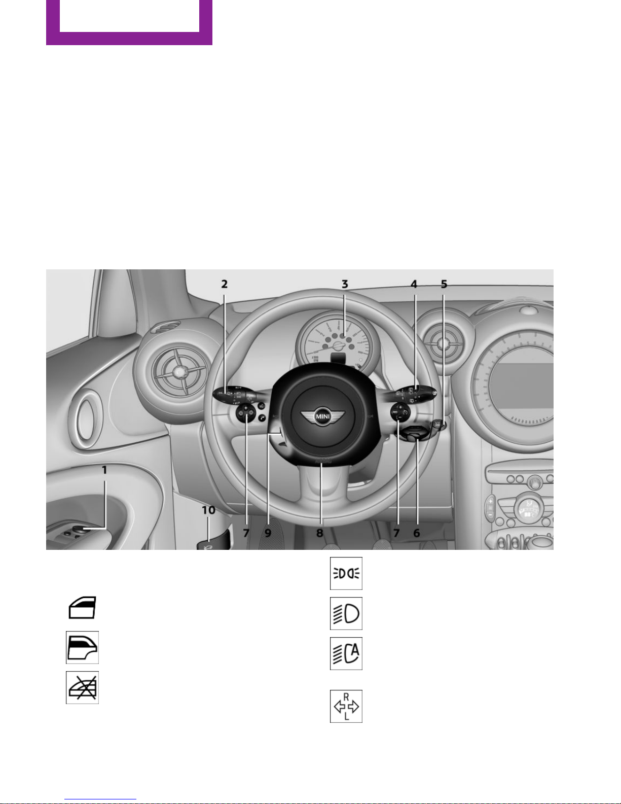
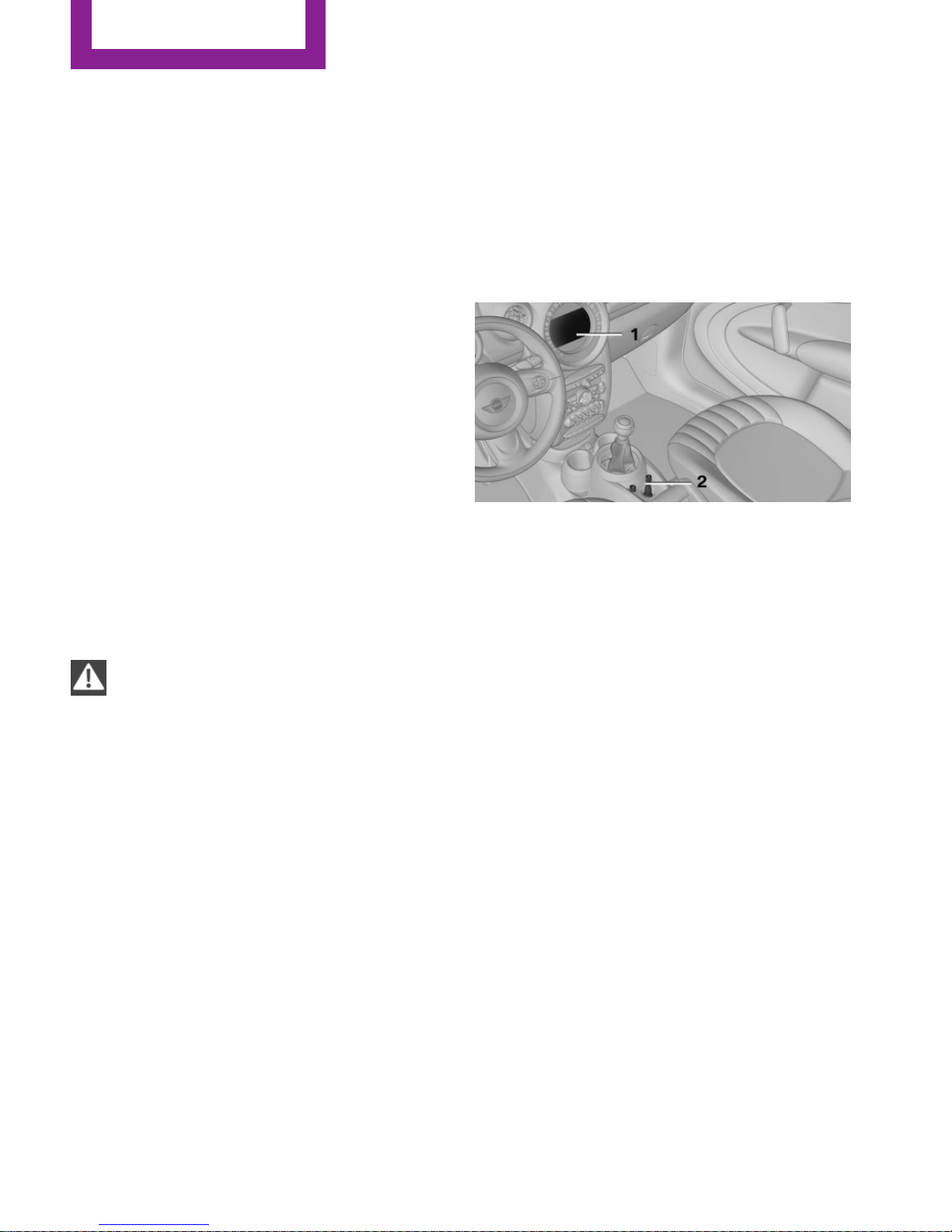
All around the steering wheel
1 Setting the exterior mirror, folding it in and
out 50
Power windows, front 42
MINI Countryman: power win‐
dows, rear 42
MINI Countryman: safety switch
for rear power windows 43
2 Parking lights 78
Low beams 78
Automatic headlamp con‐
trol 78
Adaptive Light Control 80
Turn signal 61
AT A GLANCE
Cockpit
12
Online Edition for Part no. 01 40 2 964 459 - VI/15
Page 13
High-beams 61
Headlight flasher 61
Roadside parking lights 79
Computer 69
3 Tachometer 69
Instrument lighting 80
Resetting the trip odometer 68
4 Washer/wiper system 61
5 Start/stop the engine and switch
the ignition on/off 58
6 Ignition lock 58
7 Steering wheel buttons, right
Resuming cruise control 98
Storing the speed and accelerat‐
ing or slowing down 98
Activating/deactivating cruise
control 97
Steering wheel buttons, left
Volume
Bluetooth hands-free sys‐
tem 178
Bluetooth mobile phone prepara‐
tion package 188
Activate/deactivate the voice acti‐
vation system 24
Change the radio station
Select a music track
Scroll through the redial list
8 Horn, total area
9 Adjust the steering wheel 52
10 Releasing the hood 231
Cockpit
AT A GLANCE
13
Online Edition for Part no. 01 40 2 964 459 - VI/15
Page 14
Displays
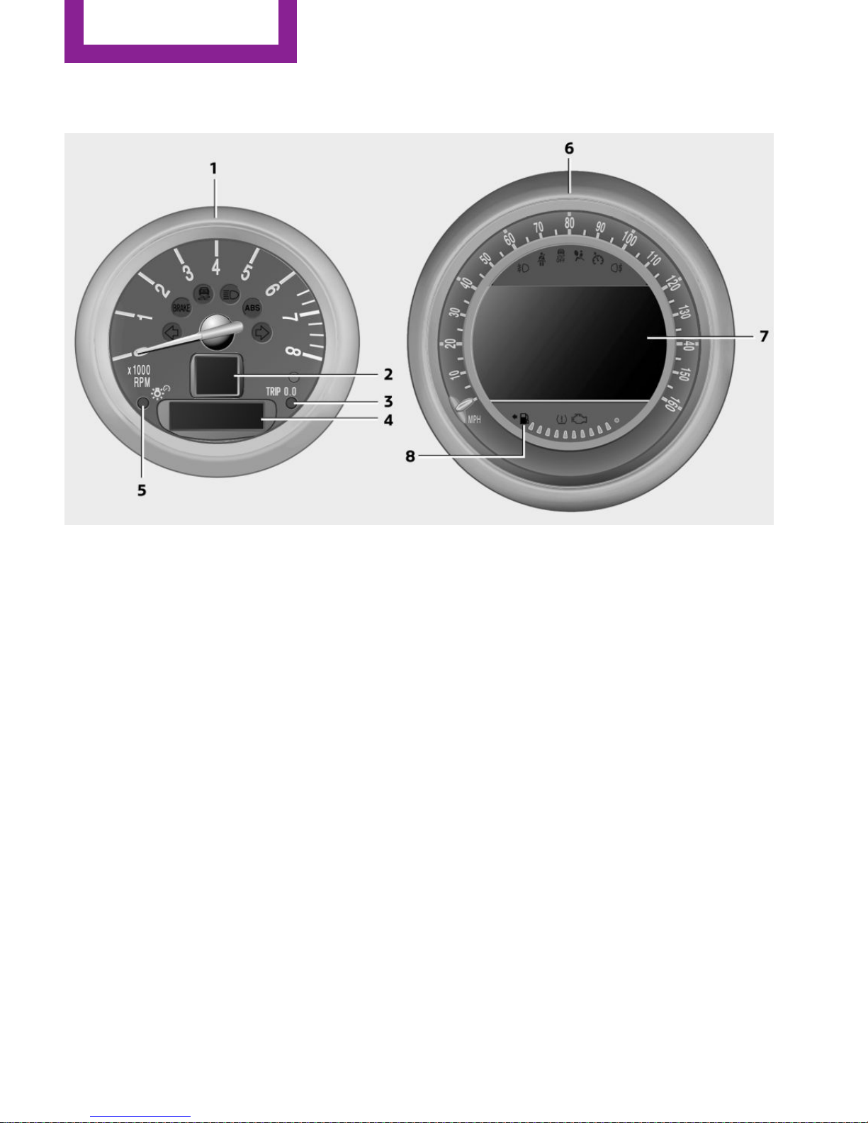
1 Tachometer 69
with indicator and warning lights 15
2 Display for
▷ Current speed 68
▷ Indicator/warning lights 15
3 Resetting the trip odometer 68
4 Display for
▷ Steptronic transmission position 65
▷ On-board computer 69
▷ Service requirements 74
▷ Odometer and trip odometer 68
▷ Flat Tire Monitor 85
▷ Tire Pressure Monitor 87
▷ Settings and information 71
▷ Personal Profile settings 31
5 Instrument lighting 80
6 Speedometer with indicator and warning
lights 15
7 Control Display 18
8 Fuel gauge 69
AT A GLANCE
Cockpit
14
Online Edition for Part no. 01 40 2 964 459 - VI/15
Page 15
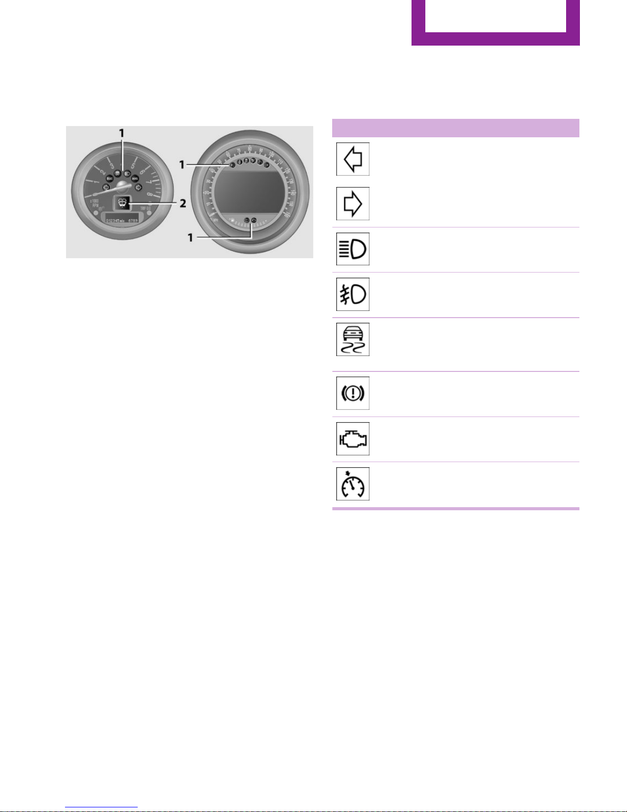
Indicator/warning lights
The principle
The indicator and warning lights can light up in
a variety of combinations and colors in display
area 1 or 2.
Several of the lights are checked for proper
functioning when the engine is started or the
ignition is switched on, and light up briefly.
Text messages
Text messages at the upper edge of the Control
Display explain the meaning of the displayed
indicator and warning lights.
Supplementary text messages
You can call up additional information, e.g., on
the cause of a malfunction and on how to re‐
spond, via Check Control, refer to page 75.
In urgent cases, this information will be shown
as soon as the corresponding light comes on.
Indicator lights without text messages
The following indicator lamps notify you that
certain functions are active:
Symbol Function or system
Turn signal, refer to page 61
High-beams/headlight flasher, refer
to page 61
Front fog lights, refer to page 80
DSC or DTC is regulating the propul‐
sive forces in order to maintain driv‐
ing stability, refer to page 93
The parking brake is set, refer to
page 60
Engine malfunction with adverse ef‐
fect on emissions, refer to page 237
Cruise control, refer to page 97
Cockpit
AT A GLANCE
15
Online Edition for Part no. 01 40 2 964 459 - VI/15
Page 16
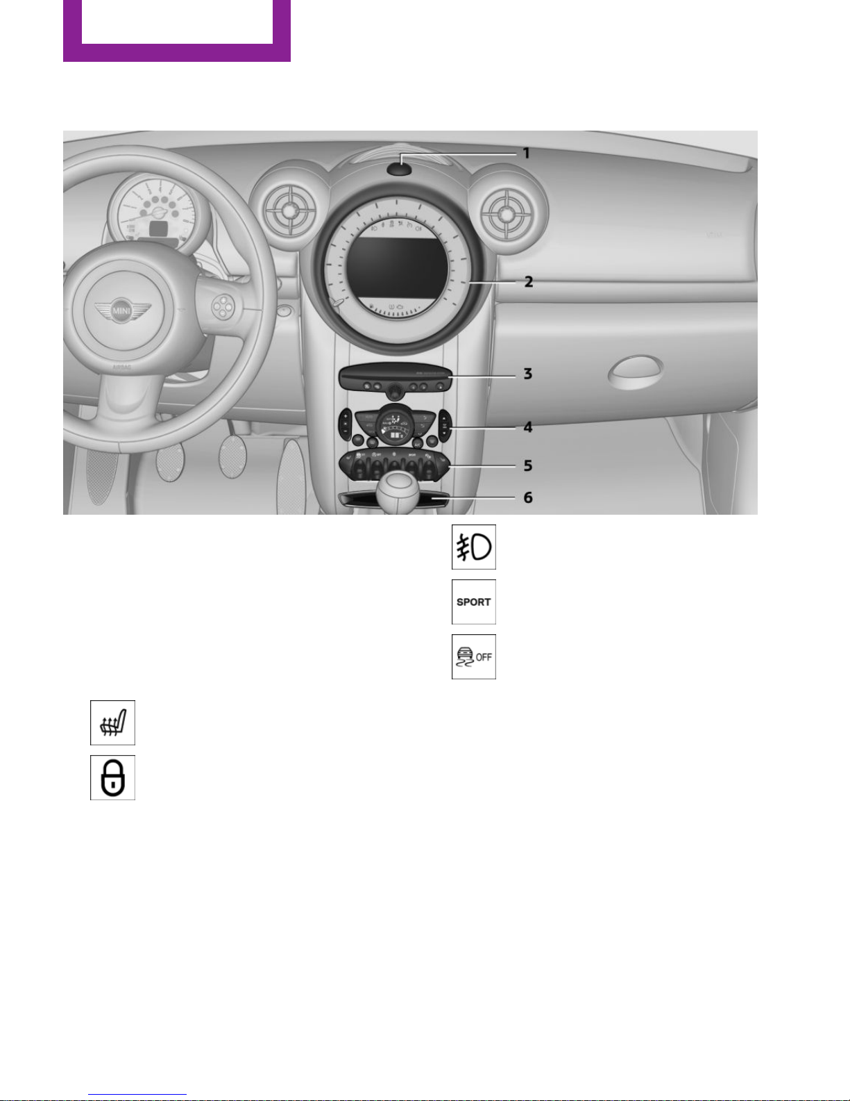
All around the center console
1 Hazard warning system
2 Speedometer with Control Display 14
3 Radio 156
CD/multimedia 156
4 Air conditioning, automatic climate con‐
trol 100
5 Buttons on the center console
Seat heating 46
Central locking, inside 34
Front fog lamps 80
Sport button 95
Driving stability control systems
DSC Dynamic Stability Con‐
trol 93
DTC Dynamic Traction Con‐
trol 94
6 Storage compartment
AT A GLANCE
Cockpit
16
Online Edition for Part no. 01 40 2 964 459 - VI/15
Page 17
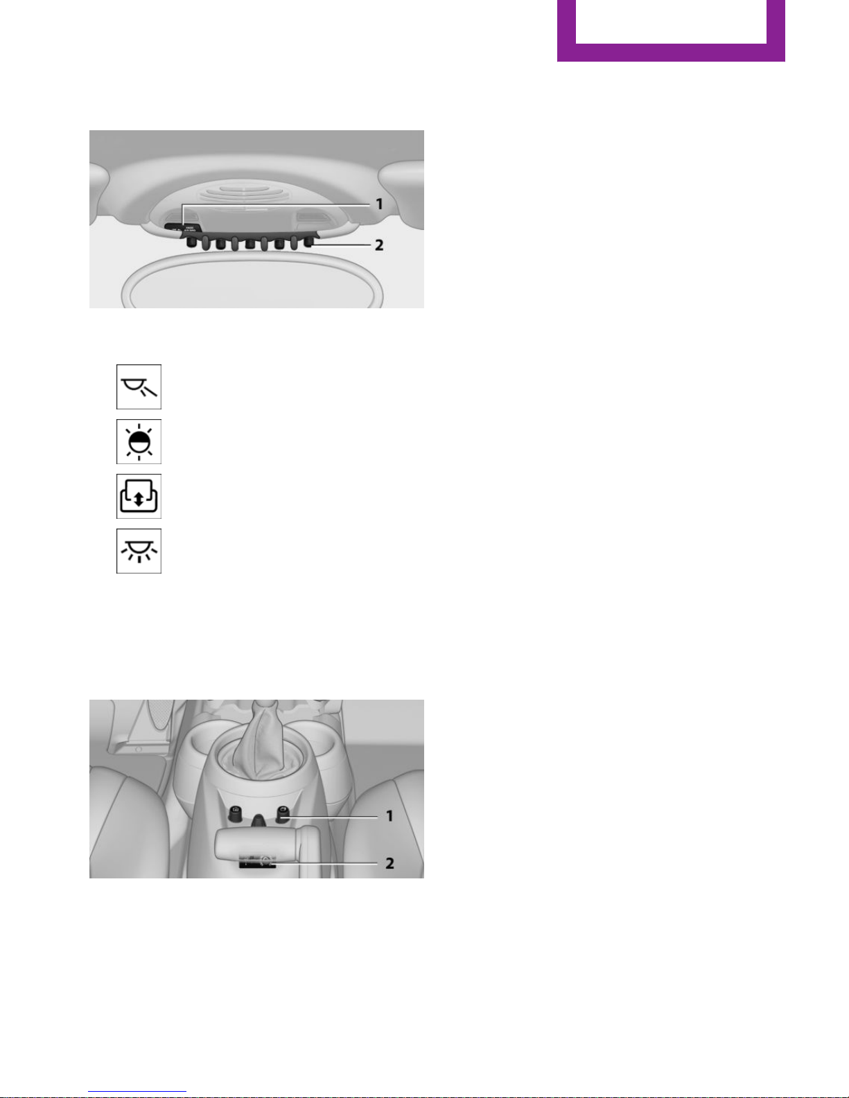
All around the roofliner
1 Indicator/warning lights for the front pas‐
senger airbags 84
2 Reading lights 81
Ambient lighting color 81
Glass sunroof, electrical 40
Interior lights 81
All around the shift/
selector lever
1 MINI joystick with buttons 19
2 USB audio interface 168
Cockpit
AT A GLANCE
17
Online Edition for Part no. 01 40 2 964 459 - VI/15
Page 18
Onboard monitor
Vehicle features and op‐
tions
This chapter describes all standard, countryspecific and optional features offered with the
series. It also describes features that are not
necessarily available in your car, e. g., due to
the selected options or country versions. This
also applies to safety-related functions and sys‐
tems.
When using the features and systems described
here, adhere to local regulations.
The concept
The onboard monitor combines the functions
of a large number of different switches. Thus,
these functions can be operated from a central
location.
WARNING
Operating the integrated information sys‐
tem and communication devices while driving
can distract from traffic. It is possible to lose
control of the vehicle. There is risk of an acci‐
dent. Only use the systems or devices when the
traffic situation allows. If necessary stop and
use the systems and devices while the vehicle is
stationary.◀
Control elements at a
glance
Control elements
1 Control Display
2 MINI joystick with buttons
The buttons can be used to open the me‐
nus directly. The MINI joystick can be used
to select menu items and create settings.
Control Display
Information
▷ To clean the Control Display, follow the care
instructions, refer to page 257.
▷ Do not place objects close to the Control
Display; otherwise, the Control Display can
be damaged.
Switch off
1.
Move the MINI joystick repeatedly to the
right until the "Options" menu appears.
AT A GLANCE
Onboard monitor
18
Online Edition for Part no. 01 40 2 964 459 - VI/15
Page 19
2. "Switch off control display"
Switching on
Press the MINI joystick to switch on.
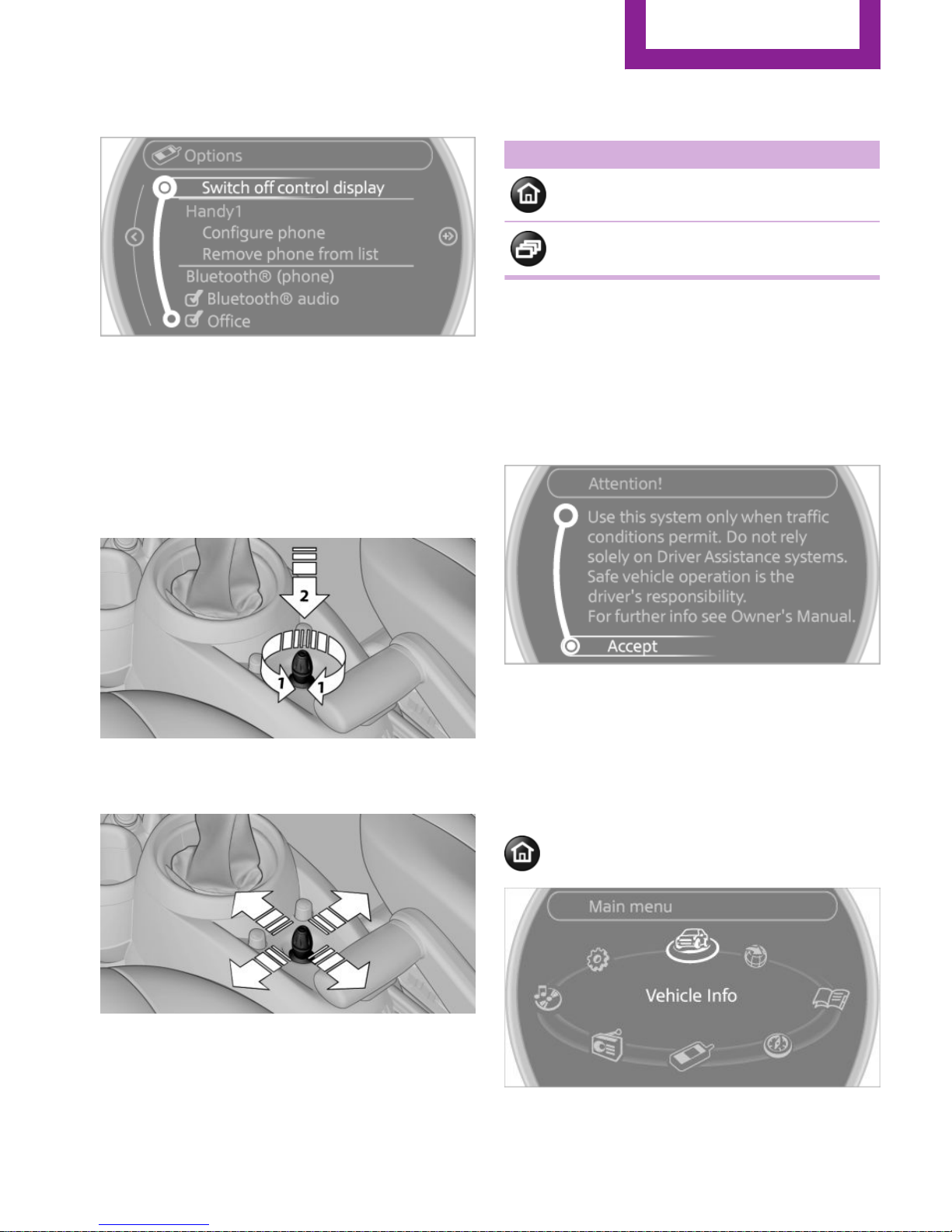
MINI joystick with buttons
Select menu items and create settings.
1.
Turn, arrow 1.
2. Press, arrow 2.
3. Move in four directions.
Buttons on the MINI joystick
Press button Function
Open the main menu.
Changes to another menu.
Operating concept
Start screen
In the radio ready state and higher, the follow‐
ing message appears on the Control Display:
To hide the message: press the MINI joystick.
The main menu is displayed.
The message is automatically hidden after ap‐
prox. 10 seconds.
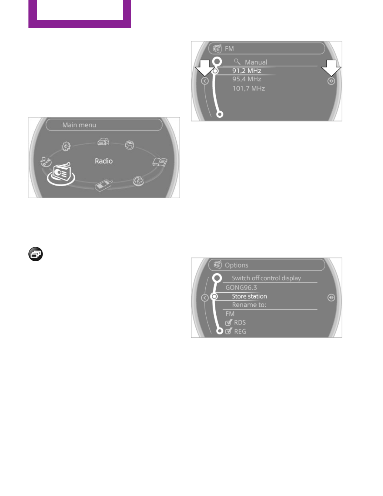
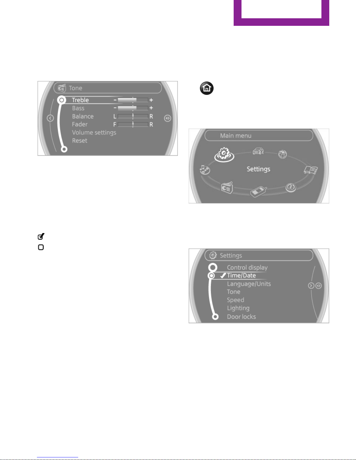
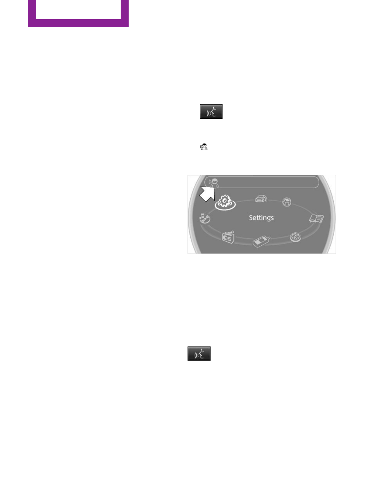
Opening the main menu
Press the button.
The main menu is displayed.
Onboard monitor
AT A GLANCE
19
Online Edition for Part no. 01 40 2 964 459 - VI/15
Page 20
All onboard monitor functions can be called up
via the main menu.
Selecting menu items
Menu items shown in white can be selected.
1. Turn the MINI joystick until the desired
menu item is highlighted.
2. Press the MINI joystick.
A new menu is displayed or the function is per‐
formed.
With the button on the MINI joystick:
Press the button.
The menu items of the main menu can be
opened consecutively by pressing the button
repeatedly.
Menu items in the Owner's Manual
In the Owner's Manual, menu items that can be
selected are set in quotation marks, e.g.,
"Settings".
Changing between panels
After a menu item is selected, e.g., "Radio", a
new panel is displayed. Panels can overlap.
▷ Move the MINI joystick to the left.
The current panel is closed and the previ‐
ous panel is displayed.
▷ Move the MINI joystick to the right.
A new panel is opened on top of the previ‐
ous display.
White arrows pointing to the left or right indi‐
cate that additional panels can be opened.
View of an opened menu
When a menu is opened, it generally opens
with the panel that was last selected in that
menu. To display the first panel of a menu:
Move the MINI joystick to the left repeatedly
until the first panel is displayed.
Opening the Options menu
Move the MINI joystick repeatedly to the right
until the "Options" menu appears.
Options menu
The "Options" menu consists of various areas:
▷ Screen settings, e.g., "Switch off control
display".
▷ Control options for the selected main
menu, e.g., for "Radio".
▷ If applicable, further operating options for
the selected menu, for instance "Store
station".
AT A GLANCE
Onboard monitor
20
Online Edition for Part no. 01 40 2 964 459 - VI/15
Page 21
Changing settings
1. Select a field.
2. Turn the MINI joystick until the desired set‐
ting is displayed.
3. Press the MINI joystick to confirm the set‐
ting.
Activating/deactivating the functions
Several menu items are preceded by a check‐
box. It indicates whether the function is acti‐
vated or deactivated. Selecting the menu item
activates or deactivates the function.
Function is activated.
The function is deactivated.
Example: setting the
clock
Setting the clock
1.
Press the button. The main menu is
displayed.
2. Turn the MINI joystick until "Settings" is
highlighted and press the MINI joystick.
3. If necessary, move the MINI joystick to the
left to display "Time/Date".
4. Turn the MINI joystick until "Time/Date" is
highlighted and press the MINI joystick.
5. Turn the MINI joystick to set the hours and
press the MINI joystick.
6. Turn the MINI joystick to set the minutes
and press the MINI joystick.
Status information
Status field
The following information is displayed in the
status field at the top right:
Onboard monitor
AT A GLANCE
21
Online Edition for Part no. 01 40 2 964 459 - VI/15
Page 22
▷ Time.
▷ Current entertainment source.
▷ Sound output, on/off.
▷ Wireless network reception strength.
▷ Telephone status.
▷ Traffic bulletin reception.
Check Control messages and entries using the
voice activation system temporarily hide the
status information.
Status field symbols
The symbols are grouped into various catego‐
ries.
Radio symbols
Symbol Meaning
HD Radio™ is switched on.
Satellite radio is switched on.
Telephone symbols
Symbol Meaning
Incoming or outgoing call.
Wireless network reception strength
Symbol flashes: searching for network.
Wireless network is not available.
Bluetooth is switched on.
Roaming is active.
Text message, e-mail was received.
Entertainment symbols
Symbol Meaning
CD player.
AUX-IN port.
Symbol Meaning
USB audio interface.
Music interface for smartphones.
Additional symbols
Symbol Meaning
Spoken instructions are switched off.
Entering letters and
numbers
General information
1.
Turn the MINI joystick: select letters or
numbers.
2. Select additional letters or numbers if
needed.
3. "OK": confirm the entry.
Symbol Function
Press the MINI joystick: delete the let‐
ter or number.
Press the MINI joystick for an ex‐
tended period: delete all letters or
numbers.
Enter a blank space.
Switching between letters and numbers
Depending on the menu, you can switch be‐
tween entering letters and numbers.
AT A GLANCE
Onboard monitor
22
Online Edition for Part no. 01 40 2 964 459 - VI/15
Page 23
Symbol Function
Enter the letters.
Enter the numbers.
Switching between upper and lower
case letters
Depending on the menu, you can switch be‐
tween entering uppercase and lowercase let‐
ters.
Symbol Function
Move the MINI joystick forward:
switch from upper to lower case
letters.
Move the MINI joystick forward:
switch from lower to upper case
letters.
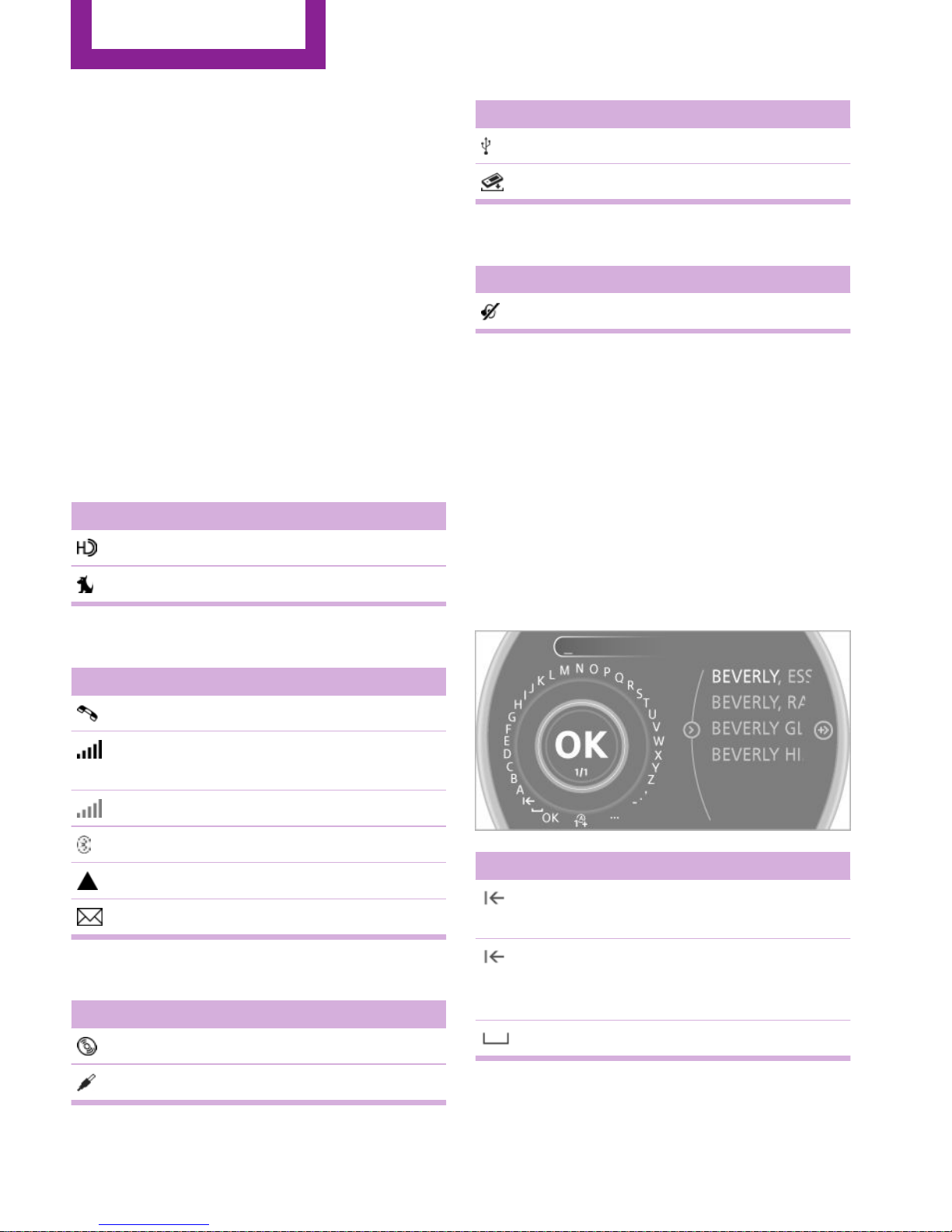
Entry comparison
Entering names and addresses: choice is nar‐
rowed down with every letter entered and let‐
ters may be added automatically.
Entries are continuously compared with data
stored in the vehicle.
▷ Only those letters are offered during input
for which data is available.
▷ Target search: names of locations may be
entered in languages available through
Control Display.
Onboard monitor
AT A GLANCE
23
Online Edition for Part no. 01 40 2 964 459 - VI/15
Page 24
Voice activation system
Vehicle features and op‐
tions
This chapter describes all standard, countryspecific and optional features offered with the
series. It also describes features that are not
necessarily available in your car, e. g., due to
the selected options or country versions. This
also applies to safety-related functions and sys‐
tems.
When using the features and systems described
here, adhere to local regulations.
The concept
▷ Most functions that are displayed on the
Control Display can be operated with the
voice activation system using spoken com‐
mands. The system prompts you to make
your entries.
▷ Functions that can only be used when the
vehicle is stationary cannot be operated us‐
ing the voice activation system.
▷ The system uses a special microphone in
the headliner on the driver's side.
▷ ›...‹ Verbal instructions in the Owner's
Manual to use with the voice activation sys‐
tem.
Requirements
Via the Control Display, set a language that is
also supported by the voice activation system
so that the spoken commands can be identi‐
fied.
Set the language, refer to page 73.
Using voice activation
Activating the voice activation system
1.
Press the button on the steering
wheel.
2. Wait for the signal.
This symbol on the Control Display indi‐
cates that the voice activation system is ac‐
tive.
3. Say the command.
The command appears on the Control Dis‐
play.
If no other commands are available, operate
the function via the onboard monitor in this
case.
Terminating the voice activation
system
Briefly press the button on the steering
wheel or ›Cancel‹.
Possible commands
Most menu items on the Control Display can be
voiced as commands.
The available commands depend on the menu
that is currently displayed on the Control Dis‐
play.
AT A GLANCE
Voice activation system
24
Online Edition for Part no. 01 40 2 964 459 - VI/15
Page 25

The functions of the main menu have short
commands.
Some list items, such as the phone book en‐
tries, can also be selected via the voice activa‐
tion system. Say the list items exactly as they
are displayed on the list.
Having possible commands read aloud
You can have the system read possible com‐
mands aloud: ›Voice commands‹.
For example, if the "CD" menu is displayed, the
commands for the operating the CD player are
read out loud.
Executing functions using short
commands
Functions on the main menu can be performed
directly by means of short commands, usually
irrespective of which menu item is currently se‐
lected, for instance ›Vehicle status‹.
List of short commands of the voice activation
system, refer to page 264.
Help dialog for the voice activation
system
Calling up help dialog: ›Help‹
Additional commands for the help dialog:
▷ ›Help with examples‹: information about
the current operating options and the most
important commands for them are an‐
nounced.
▷ ›Help with voice activation‹: information
about the principle of operation for the
voice activation system is announced.
Example: playing back a
CD
Via the main menu
The commands of the menu items are spoken
out loud, in the same way as they are selected
via the MINI joystick.
1. Switch on the Entertainment sound output
if necessary.
2.
Press the button on the steering
wheel.
3. ›C D and multimedia‹
The medium last played is played back.
4. ›C D‹
5. ›C D drive‹
The CD is played back.
6.
Press the button on the steering
wheel again to select a specific track.
7. ›Track ...‹ e.g., CD track 4.
Via short commands
Playback of the CD can also be started using a
short command.
1.
Switch on the Entertainment sound output
if necessary.
2.
Press the button on the steering
wheel.
3. ›C D drive Track ...‹ e.g., CD track 4.
Setting the voice dialog
You can set whether the system should use the
standard dialog or a shorter version.
In the shorter variant of the voice dialog, the
announcements from the system are issued in
an abbreviated form.
Voice activation system
AT A GLANCE
25
Online Edition for Part no. 01 40 2 964 459 - VI/15
Page 26

On the Control Display:
1. "Settings"
2. "Language/Units"
3. "Speech mode:"
4. Select the setting.
Adjusting the volume
Turn the volume button during the spoken in‐
structions until the desired volume is set.
▷ The volume remains constant even if the
volume of other audio sources is changed.
▷ The volume is stored for the remote control
currently in use.
Notes on Emergency Re‐
quests
Do not use the voice activation system to ini‐
tiate an Emergency Request. In stressful situa‐
tions, the voice and vocal pitch can change.
This can unnecessarily delay the establishment
of a telephone connection.
Environmental condi‐
tions
▷ Say the commands, numbers, and letters
smoothly and with normal volume, empha‐
sis, and speed.
▷ Always say commands in the language of
the voice activation system.
▷ Avoid making other noise in the vehicle
while speaking.
AT A GLANCE
Voice activation system
26
Online Edition for Part no. 01 40 2 964 459 - VI/15
Page 27

Voice activation system
AT A GLANCE
27
Online Edition for Part no. 01 40 2 964 459 - VI/15
Page 28
HANDLE ME.
Online Edition for Part no. 01 40 2 964 459 - VI/15
Page 29

AT A GLANCE
CONTROLS
DRIVING TIPS
NAVIGATION
ENTERTAINMENT
COMMUNICATION
MOBILITY
REFERENCE
Online Edition for Part no. 01 40 2 964 459 - VI/15
Page 30
Opening and closing
Vehicle features and op‐
tions
This chapter describes all standard, countryspecific and optional features offered with the
series. It also describes features that are not
necessarily available in your car, e. g., due to
the selected options or country versions. This
also applies to safety-related functions and sys‐
tems.
When using the features and systems described
here, adhere to local regulations.
Remote control/key
Buttons on the remote control
1 Opening tailgate
2 Unlocking
3 Locking
General information
Each remote control contains a rechargeable
battery that is automatically recharged when it
is in the ignition lock while the car is being
driven. Use each remote control at least twice a
year for longer road trips in order to maintain
the batteries' charge status.
In vehicles equipped with Comfort Access, the
remote control contains a replaceable battery,
refer to page 39.
The settings called up and implemented when
the vehicle is unlocked depend on which re‐
mote control is used to unlock the vehicle, Per‐
sonal Profile, refer to page 31.
In addition, information about service require‐
ments is stored in the remote control, Service
data in the remote control, refer to page 236.
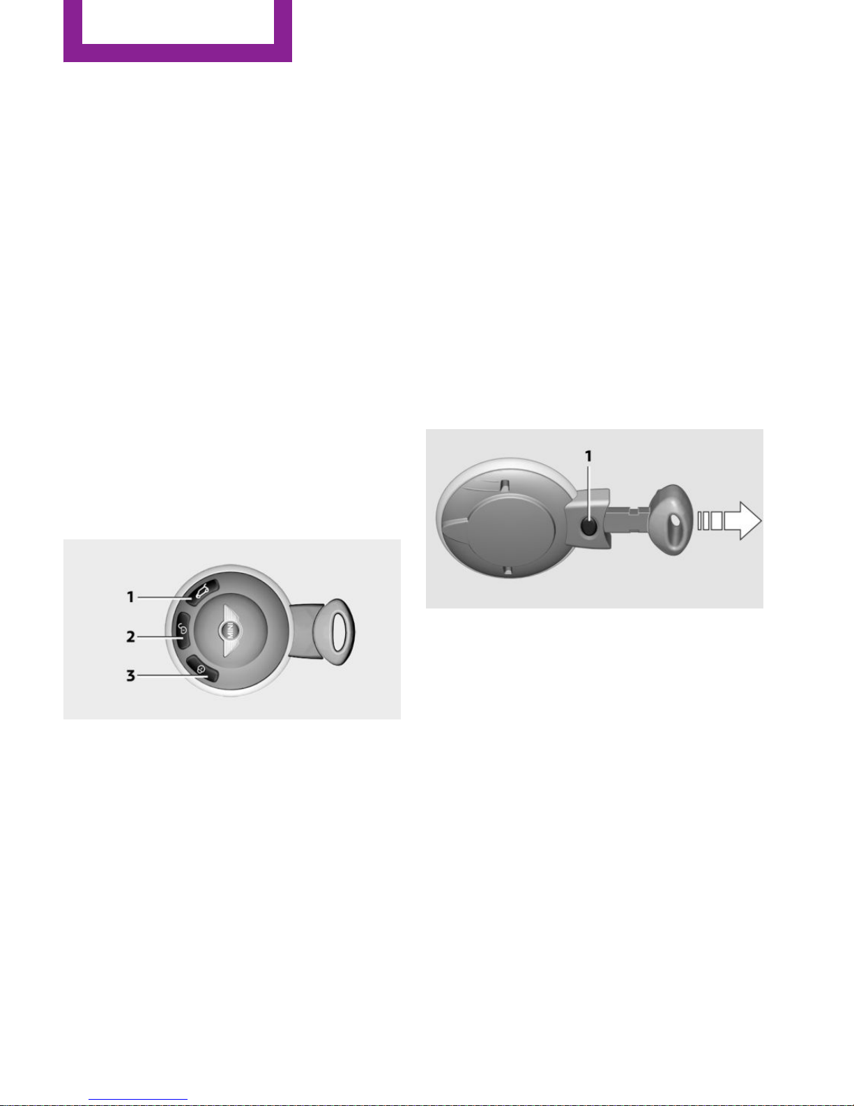
Integrated key
Press button 1 to unlock the key.
The integrated key fits the following locks:
▷ Driver's door, refer to page 34.
New remote controls
New remote controls are available from a
dealer’s service center or another qualified
service center or repair shop.
Loss of the remote controls
A lost remote control can be blocked by a
dealer’s service center or another qualified
service center or repair shop.
CONTROLS
Opening and closing
30
Online Edition for Part no. 01 40 2 964 459 - VI/15
Page 31

Personal Profile
The concept
You can set several of your vehicle's functions
to suit your personal needs and preferences.
▷ Through Personal Profile, most of these set‐
tings are stored for the remote control cur‐
rently in use.
▷ While the vehicle is being unlocked, the re‐
mote control is recognized and the settings
stored with it are called up and imple‐
mented.
▷ Your personal settings will be recognized
and called up again even if the vehicle has
been used in the meantime by someone
else with another remote control.
▷ The individual settings are stored for no
more than three remote controls.
Personal Profile settings
The following functions and settings can be
stored in a profile.
More information on the settings can be found
under:
▷ Response of the central locking system
when the car is being unlocked, refer to
page 32.
▷ Automatic locking of the vehicle, refer to
page 35.
▷ Triple turn signal activation, refer to
page 61.
▷ Settings for the displays on the onboard
monitor, in the speedometer, and in the
tachometer:
▷ 12h/24h clock format, refer to
page 72.
▷ Date format, refer to page 73.
▷ Brightness of the Control Display, refer
to page 74.
▷ Language on the Control Display, refer
to page 73.
▷ Units of measure for fuel consumption,
distance covered/remaining distances,
and temperature, refer to page 72.
▷ Light settings:
▷ Headlight courtesy delay feature, refer
to page 79.
▷ Daytime running lights, refer to
page 79.
▷ Automatic climate control, refer to
page 102: AUTO program, activating/deac‐
tivating the cooling function, setting the
temperature, air volume, and air distribu‐
tion.
▷ Entertainment:
▷ Tone settings, refer to page 154.
▷ Volume, refer to page 154.
Central locking system
The concept
The central locking system becomes active
when the driver's door is closed.
The system simultaneously engages and re‐
leases the locks on the following:
▷ Doors.
▷ Tailgate.
▷ Fuel filler flap.
Operating from the outside
▷ Via the remote control.
▷ Via the door lock.
▷ In cars with Comfort Access, via the door
handles on the driver's and front passenger
sides.
The following takes place simultaneously when
locking/unlocking the vehicle via the remote
control:
▷ Depending on the vehicle equipment, the
anti-theft protection is switched on and off
as well. The anti-theft protection makes it
Opening and closing
CONTROLS
31
Online Edition for Part no. 01 40 2 964 459 - VI/15
Page 32

impossible to unlock the doors using the
lock buttons or door handles.
▷ The welcome lamps, interior lamps, and
ambient lighting are switched on and off.
▷ The alarm system is armed or disarmed, re‐
fer to page 39.
Operating from the inside
Via the switch/button for the central locking
system, refer to page 34.
In an accident of the necessary severity, the
central locking system unlocks automatically.
The hazard warning system and interior lamps
come on.
Opening and closing:
from the outside
Using the remote control
General information
WARNING
People or animals in the vehicle can lock
the doors from the inside and lock themselves
in. The vehicle can then not be opened from
the outside. There is risk of injuries. Take the
remote control along so that the vehicle can be
opened from the outside.◀
Unlocking
Press the button. The vehicle is un‐
locked.
The welcome lamps and interior lamps are
switched on.
You can set how the vehicle is to be unlocked.
Settings are stored for the remote control cur‐
rently in use.
1. "Settings"
2. "Door locks"
3. "Unlock button"
4. Select the desired function:
▷ "All doors"
Press the button once: the en‐
tire vehicle unlocks.
▷ "Driver's door only"
Pressing the button once un‐
locks only the driver's door and the fuel
filler flap. Pressing twice unlocks the
entire vehicle.
Convenient opening
Press and hold the button on the re‐
mote control.
The power windows are opened. Depending on
the vehicle equipment, the glass sunroof is
raised.
CONTROLS
Opening and closing
32
Online Edition for Part no. 01 40 2 964 459 - VI/15
Page 33

Convenient closing with the remote control is
not possible.
Locking
Press the button.
WARNING
Unlocking from the inside is only possible
with special knowledge.
If people must spend a longer time in the vehi‐
cle while it is very hot or cold outside, there is
risk of injuries or danger to life. Do not lock the
vehicle from the outside when there are people
in it.◀
Setting the confirmation signals
Have unlocking or locking of the vehicle con‐
firmed.
1.
"Settings"
2. "Door locks"
3. "Flash when lock/unlock"
4. Press the MINI joystick.
Switching on the interior lamps
When the vehicle is locked:
Press the button.
You can also use this function to locate your ve‐
hicle in parking garages, etc.
Unlocking the tailgate
Press the button for approx. 1 second
and then release it.
Malfunctions
The function of the remote control may be im‐
paired by local radio waves. If this occurs, un‐
lock and lock the vehicle at the door lock with
the integrated key.
If it should become impossible to lock the vehi‐
cle with a remote control, the battery in the re‐
mote control is discharged. Use this remote
control on an extended trip to recharge the
battery, refer to page 30.
For US owners only
The transmitter and receiver units comply with
part 15 of the FCC/Federal Communication
Commission regulations. Operation is governed
by the following:
FCC ID:
LX8766S
LX8766E
LX8CAS
Compliance statement:
This device complies with part 15 of the FCC
Rules. Operation is subject to the following two
conditions:
▷ This device may not cause harmful interfer‐
ence, and
▷ this device must accept any interference re‐
ceived, including interference that may
cause undesired operation.
Any unauthorized modifications or changes to
these devices could void the user's authority to
operate this equipment.
Opening and closing
CONTROLS
33
Online Edition for Part no. 01 40 2 964 459 - VI/15
Page 34

Using the door lock
Sets how the vehicle is to be unlocked, refer to
page 32.
In some vehicle equipment versions, only the
driver's door can be unlocked and locked via
the door lock.
WARNING
Unlocking from the inside is only possible
with special knowledge.
If people must spend a longer time in the vehi‐
cle while it is very hot or cold outside, there is
risk of injuries or danger to life. Do not lock the
vehicle from the outside when there are people
in it.◀
Unlocking the doors and tailgate at
once
To lock all doors, the fuel filler flap, and the tail‐
gate at once:
1.
With the doors closed, lock the vehicle us‐
ing the button for the central locking sys‐
tem in the interior, refer to page 34.
2. Unlock and open the driver's or front pas‐
senger door, refer to page 35.
3. To lock the vehicle:
▷ Lock the driver's door using the
integrated key in the door lock, or
▷ Press down the lock button of the front
passenger door and close the door
from the outside.
Convenient opening and closing
In vehicles with an alarm system or Comfort Ac‐
cess, the windows and the glass sunroof can be
operated via the door lock.
Opening/closing
Turn the key to the unlock or lock position and
hold it there.
WARNING
With convenient closing, body parts can
be jammed. There is risk of injuries. Make sure
that the area of movement of the doors is clear
during convenient closing.◀
Manual operation
If an electrical malfunction occurs, the driver's
door can be unlocked or locked by turning the
integrated key to the end positions of the door
lock.
Opening and closing:
from the inside
Operation via
▷ Switch in the center console:
▷ Button in the driver's or front passenger
door:
CONTROLS
Opening and closing
34
Online Edition for Part no. 01 40 2 964 459 - VI/15
Page 35

The graphic shows the button in the MINI Pace‐
man as an example.
The switch or the buttons can be used to lock
or unlock the doors and tailgate when the
doors are closed, but they are not theft-pro‐
tected. The fuel filler flap remains unlocked.
Unlocking and opening doors
▷ Using the switch or the buttons for the cen‐
tral locking system, unlock all of the doors
at once and then pull the door opener
above the armrest, or
▷ Pull the door handle on each door twice:
the door is unlocked the first time and
opened the second time.
Locking
▷ Press the switch/button or
▷ Push down the lock button of a door. To
avoid locking yourself out by accident, the
driver's door cannot be locked at the lock
button while the door is open.
Automatic locking
In addition, it is possible to set the situations in
which the vehicle locks. The setting is stored for
the remote control in use.
1.
"Settings"
2. "Door locks"
3. Select a menu item:
▷ "Lock if no door is opened"
The central locking system locks after a
short period if no door is opened.
▷ "Lock after start. to drive"
The central locking system locks when
you start driving.
WARNING
People or animals in the vehicle can lock
the doors from the inside and lock themselves
in. The vehicle can then not be opened from
the outside. There is risk of injuries. Take the
remote control along so that the vehicle can be
opened from the outside.◀
Tailgate
Opening
The tailgate pivots back and up when it opens.
Ensure that adequate clearance is available be‐
fore opening.
CAUTION
Sharp-edged or pointed objects can hit
the rear window and heat conductors while
driving. There is risk of property damage. Cover
the edges and ensure that pointed objects do
not hit the rear window.◀
Only drive with the tailgate fully closed; other‐
wise, the tail lamps will be hidden from view
and driving safety will be compromised.
In some market-specific versions, the tailgate
can only be unlocked using the remote control
if the vehicle was unlocked first.
Opening and closing
CONTROLS
35
Online Edition for Part no. 01 40 2 964 459 - VI/15
Page 36

Opening from the inside
Press the button on the driver's footwell.
MINI Countryman
Press the top half of the MINI emblem, arrow,
or
Press the button on the remote control
for approx. 1 second and release. The tailgate is
unlocked.
MINI Paceman
Press the top half of the MINI emblem, arrow,
or
Press the button on the remote control
for approx. 1 second and release. The tailgate is
unlocked.
Closing
WARNING
Body parts can be jammed when operat‐
ing the tailgate. There is risk of injuries. Make
sure that the area of movement of the tailgate
is clear during opening and closing.◀
Make sure that the cargo cover rests on the
rubber buffers of the securing straps when clos‐
ing the tailgate.
MINI Countryman
Recessed grips on the inside trim of the tailgate
can be used to conveniently pull down the tail‐
gate.
MINI Paceman
Recessed grips on the inside trim of the tailgate
can be used to conveniently pull down the tail‐
gate.
CONTROLS
Opening and closing
36
Online Edition for Part no. 01 40 2 964 459 - VI/15
Page 37

Comfort Access
The concept
The vehicle can be accessed without activating
the remote control. All you need to do is to
have the remote control with you, e.g., in your
jacket pocket. The vehicle automatically de‐
tects the remote control when it is nearby or in
the passenger compartment.
Comfort Access supports the following func‐
tions:
▷ Unlocking/locking of the vehicle.
▷ Unlocking of the tailgate separately.
▷ Starting the engine.
Functional requirements
▷ There are no external sources of interfer‐
ence in the vicinity.
▷ To lock the vehicle, the remote control
must be located outside of the vehicle.
▷ The next unlocking and locking cycle is not
possible until after approx. 2 seconds.
▷ The engine can only be started if the re‐
mote control is inside the vehicle.
▷ The doors and tailgate must be closed to
operate the windows.
Comparison with ordinary remote
control
The functions can be controlled by pressing the
buttons or via Comfort Access.
Notes on opening and closing, refer to page 30.
If you notice a brief delay while opening or
closing the windows or glass sunroof, the sys‐
tem is checking whether a remote control is in‐
side the vehicle. Repeat the opening or closing
procedure, if necessary.
Unlocking
Press button 1.
Depending on the setting, either only the driv‐
er's door or the entire vehicle is unlocked, refer
to page 32.
Pressing the button again locks the entire vehi‐
cle again.
Convenient opening with the remote control,
refer to page 32.
Locking
Press button 1.
For Convenient closing, press and hold but‐
ton 1.
The windows and, if applicable, the glass sun‐
roof are closed in addition.
Unlocking the tailgate separately
Press the top half of the MINI emblem.
This corresponds to pressing the following but‐
ton on the remote control: .
If a remote control accidentally left in the cargo
area is detected in the locked vehicle after the
tailgate is closed, the tailgate opens again
slightly. The hazard warning system flashes and
an acoustic signal sounds.
Power windows and electrical glass
sunroof
When the engine is switched off, the windows
and the sunroof can be operated as long as
neither the doors nor the tailgate are opened.
Opening and closing
CONTROLS
37
Online Edition for Part no. 01 40 2 964 459 - VI/15
Page 38

When the door and tailgate are closed again
and the remote control is detected inside the
vehicle, the windows and the sunroof can be
operated again.
Insert the remote control into the ignition lock
to be able to operate the windows and the sun‐
roof while the engine is switched off and the
doors are open.
Switching on the radio ready state
Press the Start/Stop button to switch on the
radio ready state, refer to page 58.
Do not depress the brake or the clutch; other‐
wise, the engine will start.
Starting the engine
The engine can be started or the ignition can
be switched on, refer to page 58, when a re‐
mote control is inside the vehicle. It is not nec‐
essary to insert a remote control into the igni‐
tion lock.
Switching off the engine in cars with
Steptronic transmission
The engine can only be switched off with the
selector lever in position P, refer to page 65.
To switch off the engine with the selector lever
in position N, the remote control must be in‐
serted in the ignition lock.
Before driving a vehicle with Steptronic
transmission into a car wash
1.
Insert the remote control into the ignition
switch.
2. Depress the brake pedal.
3. Move the selector lever to position N.
4. Switch the engine off.
The vehicle can roll.
Malfunction
The Comfort Access functions can be disturbed
by local radio waves, such as by a mobile
phone in the immediate vicinity of the remote
control or when a mobile phone is being
charged in the vehicle.
If this occurs, open or close the vehicle using
the buttons on the remote control or use the
integrated key in the door lock.
To start the engine afterward, insert the remote
control into the ignition switch.
Warning lights
The warning light in the instrument
cluster lights up when you attempt to
start the engine: the engine cannot be
started.
The remote control is not in the vehicle or has a
malfunction. Take the remote control with you
inside the vehicle or have it checked. If neces‐
sary, insert another remote control into the ig‐
nition switch.
The warning lamp in the instrument
cluster lights up while the engine is run‐
ning: the remote control is no longer in‐
side the vehicle.
After switching off the engine, the engine can
only be started again within approx. 10 sec‐
onds if no door has been opened.
The indicator lamp lights up and a mes‐
sage appears on the Control Display: re‐
place the remote control battery.
CONTROLS
Opening and closing
38
Online Edition for Part no. 01 40 2 964 459 - VI/15
Page 39

Replacing the battery
The remote control for Comfort Access contains
a battery that will need to be replaced from
time to time.
1. Remove the cover.
2. Insert a new battery with the positive side
facing upwards.
3. Press the cover closed.
Take the old battery to a collection point,
a dealer’s service center or another quali‐
fied service center or repair shop.
Alarm system
The concept
The enabled alarm system reacts to the follow‐
ing:
▷ Opening of a door, the hood or the tailgate.
▷ Movements inside the vehicle.
▷ Changes in the vehicle tilt, e.g., during at‐
tempts to steal a wheel or tow the car.
▷ Interruptions in battery voltage.
Depending on the market-specific version, the
alarm system briefly signals unauthorized entry
attempts by:
▷ By sounding an acoustic alarm.
▷ By switching on the hazard warning system.
Arming and disarming the alarm system
General information
When the vehicle is locked and unlocked, the
alarm system is armed and disarmed at the
same time.
Door lock and armed alarm system
Unlocking via the door lock will trigger the
alarm on some market-specific versions.
To stop this alarm, unlock the vehicle with the
remote control or switch on the ignition.
Tailgate with armed alarm system
The tailgate, refer to page 33, can also be
opened when the alarm system is armed.
Press the button on the remote con‐
trol.
When you subsequently close the tailgate, it is
again locked and monitored.
Unlocking via the door lock will trigger the
alarm on some market-specific versions.
Switching off the alarm
▷ Unlock the vehicle using the remote con‐
trol, refer to page 32.
▷ Insert the remote control all the way into
the ignition lock.
▷ With Comfort Access and if you are carrying
the remote control with you, push the but‐
ton on the door lock.
Display on the tachometer
When the alarm system is being armed, all LEDs
pulse like a heartbeat. One LED flashes after
approx. 16 minutes.
Opening and closing
CONTROLS
39
Online Edition for Part no. 01 40 2 964 459 - VI/15
Page 40

▷ LEDs pulse or LED flashes: system is armed.
▷ One LED flashes at short intervals: the
doors, hood, or tailgate is not properly
closed.
Even if these are not closed fully, the re‐
maining items are locked and the LEDs
pulse after approx. 10 seconds for approx.
16 minutes; afterwards, one LED flashes.
The interior motion sensor is not activated.
▷ The LEDs go out after the vehicle is un‐
locked: the vehicle has not been tampered
with in the meantime.
▷ The LEDs flash after the vehicle is unlocked
until the remote control is inserted in the
ignition, but for no longer than approx.
5 minutes: the vehicle has been tampered
with in the meantime.
Panic mode
You can trigger the alarm system if you find
yourself in a dangerous situation.
Press the button on the remote control
for at least two seconds.
To switch off the alarm: press any button on the
remote control.
Tilt alarm sensor
The tilt of the vehicle is monitored.
The alarm system responds in situations such as
attempts to steal a wheel or tow the car.
Interior motion sensor
For the interior motion sensor to function prop‐
erly, the windows and the glass sunroof must
be closed.
Avoiding unintentional alarms
The tilt alarm sensor and interior motion sensor
can be switched off together, such as in the fol‐
lowing situations:
▷ In duplex garages.
▷ During transport on car-carrying trains, at
sea or on a trailer.
▷ When animals are to remain in the vehicle.
Switching off the tilt alarm sensor and
interior motion sensor
▷
Press the button on the remote
control twice in succession.
▷ Lock the vehicle twice with the integrated
key.
The LEDs flash in short succession for approx.
2 seconds. The tilt alarm sensor and interior
motion sensor remain switched off until the ve‐
hicle is unlocked and locked again.
Glass sunroof, electrical
General information
WARNING
Body parts can be jammed on operating
the glass sunroof. There is risk of injuries. Make
sure that the area of movement of the glass
sunroof is clear during opening and closing.◀
WARNING
Unattended children or animals can move
the vehicle and endanger themselves and traf‐
fic, e.g. with the following actions:
▷ Pressing the Start/Stop button.
▷ Releasing the parking brake.
CONTROLS
Opening and closing
40
Online Edition for Part no. 01 40 2 964 459 - VI/15
Page 41

▷ Opening and closing of doors or windows.
▷ Shifting the selector lever into neutral.
▷ Using vehicle equipment.
There is risk of accidents or injuries. Do not
leave children or animals unattended in the ve‐
hicle. Carry remote control along when exiting
and lock the vehicle.◀
Convenient operation via:
▷ Door lock, refer to page 34
▷ Comfort Access, refer to page 37
Tilting the glass sunroof
MINI Countryman:
▷ Press the switch back to the resistance
point and hold.
Both glass sunroofs are raised.
Releasing stops the motion.
▷ With the ignition switched on, press the
switch back past the resistance point.
Both closed glass sunroofs are raised fully.
Pressing again stops the motion.
MINI Paceman:
▷ Press the switch back to the resistance
point and hold.
The front glass sunroof is raised.
Releasing stops the motion.
▷ With the ignition switched on, press the
switch back past the resistance point.
The front glass sunroof is fully raised.
Pressing again stops the motion.
Opening, closing
MINI Countryman:
▷ In the raised position with the ignition
switched on, press the switch back and
hold.
The front glass sunroof is opened. The rear
glass sunroof is closed.
Releasing stops the motion.
The same method is used to close the glass
sunroof, in this case by pressing the switch for‐
ward.
The front glass sunroof remains in the raised
position. The rear glass sunroof is raised. Press‐
ing again closes both sunroofs completely.
MINI Paceman:
▷ In the raised position with the ignition
switched on, press the switch back and
hold.
The front glass sunroof is opened.
Releasing stops the motion.
The same method is used to close the glass
sunroof, in this case by pressing the switch for‐
ward.
The front glass sunroof remains in the raised
position. Pressing again closes the roof com‐
pletely.
Roller sunblind
The roller sunblind can be opened and closed
separately from the glass sunroof.
After a power failure
After a power failure, it could happen that the
sunroof can only be raised. In this case, have
the system initialized. The manufacturer of your
MINI recommends that this work be performed
by a dealer’s service center or another qualified
service center or repair shop.
Opening and closing
CONTROLS
41
Online Edition for Part no. 01 40 2 964 459 - VI/15
Page 42

Power windows
General information
WARNING
When operating the windows, body parts
and objects can be jammed. There is risk of in‐
juries or risk of property damage. Make sure
that the area of movement of the windows is
clear during opening and closing.◀
WARNING
Unattended children or animals can move
the vehicle and endanger themselves and traf‐
fic, e.g. with the following actions:
▷ Pressing the Start/Stop button.
▷ Releasing the parking brake.
▷ Opening and closing of doors or windows.
▷ Shifting the selector lever into neutral.
▷ Using vehicle equipment.
There is risk of accidents or injuries. Do not
leave children or animals unattended in the ve‐
hicle. Carry remote control along when exiting
and lock the vehicle.◀
If, after having been opened and closed a num‐
ber of times in close succession, a window can
only be closed, the system is overheated. Let
the system cool down for several minutes with
the ignition switched on or the engine running.
Opening, closing
Front windows
To open:
▷ Press the switch to the resistance point. The
window opens while the switch is held.
▷ Press the switch beyond the resistance
point. The window opens automatically in
the radio ready state and higher.
Press again briefly to stop the opening pro‐
cedure.
To close:
▷ Pull the switch to the resistance point. The
window closes while the switch is held.
▷ Pull the switch beyond the resistance point.
The window closes automatically.
Pressing the switch stops the motion.
MINI Countryman: rear windows
To open:
▷ Press the switch to the resistance point. The
window opens while the switch is held.
▷ Press the switch beyond the resistance
point. The window opens automatically in
the radio ready state and higher.
To close:
▷ Pull the switch to the resistance point. The
window closes while the switch is held.
▷ Pull the switch beyond the resistance point.
The window closes automatically.
Pressing the switch stops the motion.
After the ignition is switched off
The windows can be operated for approx. 1 mi‐
nute after the remote control is removed or the
ignition is switched off.
CONTROLS
Opening and closing
42
Online Edition for Part no. 01 40 2 964 459 - VI/15
Page 43

Pinch protection system
If the closing force exceeds a specific value as a
window closes, the closing action is inter‐
rupted.
The window reopens slightly.
WARNING
When operating the windows, body parts
and objects can be jammed. There is risk of in‐
juries or risk of property damage. Make sure
that the area of movement of the windows is
clear during opening and closing.◀
WARNING
Accessories on the windows such as an‐
tennas can impact jam protection. There is risk
of injuries. Do not install accessories in the area
of movement of the windows.◀
Closing without the pinch protection
system
WARNING
When operating the windows, body parts
and objects can be jammed. There is risk of in‐
juries or risk of property damage. Make sure
that the area of movement of the windows is
clear during opening and closing.◀
If there is an external danger or, for example, if
ice on the windows prevents a window from
closing normally, the window can be closed
manually.
1.
Pull the switch past the resistance point and
hold it there. Pinch protection is limited and
the window reopens slightly if the closing
force exceeds a certain value.
2. Pull the switch past the resistance point
again within approx. 4 seconds and hold it
there.
The window closes without pinch protec‐
tion.
MINI Countryman: safety switch
With the safety switch, the rear windows are
prevented from being opened or closed via the
switches in the rear passenger area, such as by
children.
Press the button. The LED lights up if the safety
function is switched on.
WARNING
When operating the windows, body parts
and objects can be jammed. There is risk of in‐
juries or risk of property damage. Make sure
that the area of movement of the windows is
clear during opening and closing.◀
Opening and closing
CONTROLS
43
Online Edition for Part no. 01 40 2 964 459 - VI/15
Page 44

Adjusting
Vehicle features and op‐
tions
This chapter describes all standard, countryspecific and optional features offered with the
series. It also describes features that are not
necessarily available in your car, e. g., due to
the selected options or country versions. This
also applies to safety-related functions and sys‐
tems.
When using the features and systems described
here, adhere to local regulations.
Sitting safely
The ideal seating position can make a vital con‐
tribution to relaxed, fatigue-free driving.
The seating position plays an important role in
an accident in combination with:
▷ Safety belts, refer to page 46
▷ Head restraints, refer to page 49.
▷ Airbags, refer to page 82.
Seats
Note before adjusting
WARNING
Seat adjustments while driving can lead
to unexpected movements of the seat. Vehicle
control could be lost. There is risk of an acci‐
dent. Only adjust the side on the driver's side
when the vehicle is stationary.◀
WARNING
With a backrest inclined too far to the
rear, the protective effect of the safety belt
cannot be ensured anymore. There is a danger
of sliding under the safety belt in an accident.
There is risk of injuries or danger to life. Adjust
the seat prior to starting the trip. Adjust the
backrest in an as upright position as possible
and do not adjust again while driving.◀
WARNING
There is risk of jamming when moving the
seats. There is risk of injuries or risk of property
damage. Make sure that the area of movement
of the seat is clear prior to any adjustment.◀
Front seat adjustment
Forward/backward
Pull the lever, arrow 1, and slide the seat into
the desired position, arrows 2.
After releasing the lever, move the seat forward
or back slightly to make sure it engages prop‐
erly.
CONTROLS
Adjusting
44
Online Edition for Part no. 01 40 2 964 459 - VI/15
Page 45

Height
Pull the lever up or push it down repeatedly, ar‐
rows 1, until the desired height is reached, ar‐
rows .
Backrest
MINI Countryman:
Pull the lever, arrow 1, and apply your weight
to the backrest or lift it off, as necessary.
MINI Paceman:
Pull the lever, arrow 1, and apply your weight
to the backrest or lift it off, as necessary, ar‐
rows 2.
Lumbar support
You can also adjust the contour of the backrest
to obtain additional support in the lumbar re‐
gion.
The upper hips and spinal column receive sup‐
plementary support to help you maintain a re‐
laxed, upright sitting position.
The graphic shows the MINI Countryman as an
example.
Turn the wheel to increase or decrease the cur‐
vature.
MINI Countryman: rear seat adjustment
Forward/backward
Pull the lever and slide the seat into the desired
position.
Release the lever and move the seat slightly
forward or back so that it engages properly.
Backrest
Adjust the backrest tilt, refer to page 111.
Adjusting
CONTROLS
45
Online Edition for Part no. 01 40 2 964 459 - VI/15
Page 46

MINI Paceman: entry in the rear
1. Pull the lever on the back of the seat up‐
ward, arrow 1.
The backrest folds forward.
2. Push against the backrest to move the seat
forward, arrow 2.
To make it easier to enter the car in the rear,
push back the safety belt on the lower belt
guide rail if necessary.
Restoring the original seat position
The driver's seat has a mechanical memory
function for the forward/backward seat setting
and the backrest setting.
1.
Push the seat back to the original position.
Do not fold back the backrest until the seat
is in its original position; otherwise, the seat
will engage in its current position. If this
happens, adjust the forward/backward po‐
sition manually, refer to page 44.
2. Fold back the backrest to lock the seat.
WARNING
There is risk of jamming when moving the
seats. There is risk of injuries or risk of property
damage. Make sure that the area of movement
of the seat is clear prior to any adjustment.◀
WARNING
Unexpected movements of the backrest
while driving may occur due to an unlocked
backrest. Vehicle control could be lost. There is
risk of injuries. Fold back and lock the backrests
before driving.◀
Seat heating
Switching on
The temperature setting progresses one step
through its control sequence each time you
press the button. The maximum temperature is
reached when three LEDs are lit.
If the trip is continued within approx. 15 mi‐
nutes, the seat heating is activated automati‐
cally with the temperature set last.
The temperature is reduced, if need be, down
to no heat in order to reduce the load on the
battery. The LEDs remain lit.
Switch off
Press the button longer.
Safety belts
Number of safety belts
Your vehicle has been fitted with four or five
safety belts for the safety of you and your pas‐
sengers.
However, they can only offer protection when
adjusted correctly.
Information
Always make sure that safety belts are being
worn by all occupants before driving away.
Although airbags enhance safety by providing
added protection, they are not a substitute for
safety belts.
CONTROLS
Adjusting
46
Online Edition for Part no. 01 40 2 964 459 - VI/15
Page 47

The shoulder strap's anchorage point will be
correct for adult seat occupants of every build if
the seat is correctly adjusted.
WARNING
If the safety belt is used by more than
one person, the protective effect of the safety
belt cannot be ensured anymore. There is risk
of injuries or danger to life. Do not allow more
than one person to wear a single safety belt. In‐
fants and children are not allowed in an occu‐
pant's lap, but must be transported and respec‐
tively secured in designated child restraint
systems.◀
WARNING
The protective effect of the safety belts
can be limited or lost when safety belts are fas‐
tened incorrectly. An incorrectly fastened safety
belt can cause additional injuries, e.g. in the
event of an accident or during braking and eva‐
sive maneuvers. There is risk of injuries or dan‐
ger to life. Make sure that all occupants are
wearing safety belts correctly.◀
WARNING
With a rear backrest that is not locked,
the protective function of the middle safety belt
is not guaranteed. There is risk of injuries or
danger to life. If you are using the middle safety
belt, lock the wider rear backrest.◀
Correct use of safety belts
▷ Wear the belt twist-free and as tight to your
body as possible over your lap and should‐
ers.
▷ Wear the belt deep on your hips over your
lap. The belt may not press on your stom‐
ach.
▷ Do not wear the belt on your throat, rub it
on sharp edges, guide it or jam it in across
hard or fragile objects.
▷ Avoid thick clothing.
▷ Re-tighten the belt frequently upward
around your upper body.
Buckling the belt
MINI Countryman:
MINI Paceman:
Make sure you hear the latch plate engage in
the belt buckle.
The shoulder strap's anchorage point will be
correct for adult seat occupants of every build if
the seat is correctly adjusted, refer to page 44.
Unbuckling the belt
1.
Hold the belt firmly.
2. Press the red button in the belt buckle.
3. Guide the belt back into its reel.
Securing the buckle tongues
If the front passenger seat is not occupied, slide
the buckle tongue up to the belt stop knob with
the clip.
When the outer rear seats are not occupied, the
buckle tongues of the rear seats can be slid up
to the cargo area trim with the clip.
This helps avoid annoying noises when driving.
Adjusting
CONTROLS
47
Online Edition for Part no. 01 40 2 964 459 - VI/15
Page 48

MINI Countryman: center safety belt of
rear seat
The belt buckle embossed with the word CEN‐
TER is intended exclusively for use by passen‐
gers riding in the center position.
If the center safety belt in the rear is used, the
backrests must be locked, refer to page 112.
The safety belt will not have a restraining effect
if the backrest is not locked.
Belt holder in the headliner
The holder for the safety belt is located in the
headliner.
1 Opening for the safety belt
2 Holder for the small buckle tongue
Take the small buckle tongue out of the holder.
Move both buckle tongues downward.
Closing
Insert the small buckle tongue 2 of the safety
belt into the small belt buckle 3.
Opening
Press the red button on the small belt buckle 3
with buckle tongue 1.
When the center safety belt is locked:
Press the red button 3 with the buckle tongue
of the outer left safety belt.
Putting on the belt
1 Large buckle tongue
2 Small buckle tongue
3 Small belt buckle
4 Large belt buckle
Buckle tongue 1 must be inserted in belt
buckle 4. Make sure you hear the buckle
tongue engage in the belt buckle.
Insert the buckle tongue into the belt buckle in
such a way that the belt lies smoothly against
the body of the buckled person and is not
twisted.
Stowing the center safety belt
If the center seat is not occupied, insert the belt
buckles 3 and 4 into the respective holders, ar‐
rows.
CONTROLS
Adjusting
48
Online Edition for Part no. 01 40 2 964 459 - VI/15
Page 49

Move the buckle tongues to the belt holder on
the headliner, refer to page 48, and insert them
into the provided holders.
Safety belt reminder for driver's seat
and front passenger seat
The indicator lamps light up and a sig‐
nal sounds. In addition, a message ap‐
pears on the Control Display. Check
whether the safety belt has been fas‐
tened correctly.
Damage to safety belts
In the case of strain caused by accidents or
damage:
Have the safety belts, including the safety belt
tensioners, replaced and have the belt anchors
checked.
WARNING
The protective effect of the safety belts
may not be fully functional or fail in the follow‐
ing situations:
▷ Safety belts are damaged, soiled or
changed in any other way.
▷ Safety belt buckle is damaged or heavily
soiled.
▷ Belt tensioners or belt retractors were
modified.
Safety belts can be imperceptibly damaged in
the event of an accident. There is risk of injuries
or danger to life. Do not modify safety belts,
safety belt buckles, belt tensioners, belt retrac‐
tors or belt anchors and keep them clean. After
an accident, have the safety belts checked by a
dealer’s service center or another qualified
service center or repair shop.◀
Head restraints
Information
WARNING
A missing protective effect due to re‐
moved or not correctly adjusted head restraints
can cause injuries in the head and neck area.
There is risk of injuries. Install head restraints
on occupied seats prior to driving and make
sure that the center of the head restraint sup‐
ports the back of the head at eye level.◀
WARNING
Objects on the head restraint reduce the
protective effect in the head and neck area.
There is risk of injuries.
▷ Do not use seat or head restraint covers.
▷ Do not hang objects, e.g., clothes hangers,
directly on the head restraint.
▷ Only use accessories that have been deter‐
mined to be safe for attachment to a head
restraint.
▷ Do not use any accessories, e.g. pillows,
while driving.◀
Correctly set head restraint
A correctly adjusted head restraint reduces the
risk of spinal injury in the event of an accident.
Height
Adjust the head restraint so that its center is
approx. at ear level.
MINI Countryman: the center rear head re‐
straint is not height adjustable.
Adjusting
CONTROLS
49
Online Edition for Part no. 01 40 2 964 459 - VI/15
Page 50

Height adjustment
To raise: pull.
To lower: press the button, arrow 1, and push
the head restraint down until it engages.
MINI Countryman: additionally press button 2
on the rear head restraints only if you wish to
remove them.
Removing
Only remove the head restraint if no one will be
sitting in the seat in question.
Front
1.
Pull the head restraint upward as far as
possible.
2. MINI Countryman: tilt the backrest back
slightly.
MINI Paceman: fold the backrest forward if
necessary.
3. Press button 1 and pull out the head re‐
straint all the way to the stop.
MINI Countryman: additionally press but‐
ton 2 using a suitable tool.
4. Pull out the head restraint.
5. Fold back the backrest.
Rear
1. Pull the head restraint upward as far as
possible.
2. Fold the backrest forward slightly.
3. Press button 1 and pull out the head re‐
straint all the way to the stop.
MINI Countryman: additionally press but‐
ton 2 using a suitable tool.
4. Pull out the head restraint completely.
5. Fold back the rear seat backrest.
Mirrors
Exterior mirrors
General information
The mirror on the passenger side is more
curved than the driver's mirror.
WARNING
Objects reflected in the mirror are closer
than they appear. The distance to the traffic
behind could be incorrectly estimated, e.g.
while changing lanes. There is risk of an acci‐
dent. Estimate the distance to the traffic behind
by looking over your shoulder.◀
CONTROLS
Adjusting
50
Online Edition for Part no. 01 40 2 964 459 - VI/15
Page 51

Overview
1 Adjusting
2 Selecting the left/right mirror
3 Folding the mirror in and out
Selecting a mirror
To change to the other mirror: slide the
mirror switch over.
Adjusting electrically
The setting corresponds to the direction
in which the button is pressed.
Adjusting manually
If an electrical malfunction occurs, for example,
press the edges of the mirror glass.
Folding the mirror in and out
Press button 3.
The mirror can be folded in up to a vehicle
speed of approx. 20 mph/30 km/h.
For example, this is advantageous
▷ In car washes.
▷ In narrow streets.
▷ For folding back mirrors that were folded
away manually.
CAUTION
Depending on the vehicle width, the ve‐
hicle can be damaged in car washes. There is
risk of property damage. Before washing, fold
in the mirrors by hand or with the button.◀
Automatic heating
Both exterior mirrors are heated automatically
while the engine is running or the ignition is
switched on when the external temperature is
below a certain value.
Interior rearview mirror
To reduce the blinding effect from the rear
when driving at night: turn the knob.
Interior rearview and exterior mirrors,
automatic dimming feature
Two photocells are used for control:
▷ In the mirror frame, see arrow.
▷ On the back of the mirror.
For proper operation:
▷ Keep the photocells clean.
Adjusting
CONTROLS
51
Online Edition for Part no. 01 40 2 964 459 - VI/15
Page 52

▷ Do not cover the area between the inside
rearview mirror and the windshield.
▷ Do not apply stickers to the windshield in
front of the mirror.
Steering wheel
Adjusting
WARNING
Steering wheel adjustments while driving
can lead to unexpected steering wheel move‐
ments. Vehicle control could be lost. There is
risk of an accident. Adjust the steering wheel
while the vehicle is stationary only.◀
1.
Fold the lever down.
2. Move the steering wheel to the preferred
height and angle to suit your seating posi‐
tion.
3. Fold the lever back.
CONTROLS
Adjusting
52
Online Edition for Part no. 01 40 2 964 459 - VI/15
Page 53

Transporting children safely
Vehicle features and op‐
tions
This chapter describes all standard, countryspecific and optional features offered with the
series. It also describes features that are not
necessarily available in your car, e. g., due to
the selected options or country versions. This
also applies to safety-related functions and sys‐
tems.
When using the features and systems described
here, adhere to local regulations.
The right place for chil‐
dren
Information
WARNING
Unattended children or animals can move
the vehicle and endanger themselves and traf‐
fic, e.g. with the following actions:
▷ Pressing the Start/Stop button.
▷ Releasing the parking brake.
▷ Opening and closing of doors or windows.
▷ Shifting the selector lever into neutral.
▷ Using vehicle equipment.
There is risk of accidents or injuries. Do not
leave children or animals unattended in the ve‐
hicle. Carry remote control along when exiting
and lock the vehicle.◀
Children should always be in the rear
WARNING
Persons shorter than 5 ft, 150 cm cannot
correctly fasten the safety belt without suitable
additional restraint systems. The protective ef‐
fect of the safety belts can be limited or lost
when safety belts are fastened incorrectly. An
incorrectly fastened safety belt can cause addi‐
tional injuries, e.g. in the event of an accident
or during braking and evasive maneuvers.
There is risk of injuries or danger to life. Secure
persons shorter than 5 ft, 150 cm using suitable
restraint systems.◀
Accident research shows that the safest place
for children is on the rear seat.
Only transport children younger than 12 years
of age (13 years of age) or shorter than 5 ft,
150 cm in the rear in child restraint systems
suitable for the age, weight and size of the
child.
Children 13 years of age or older must wear a
safety belt as soon as a suitable child restraint
system can no longer be used due to their age,
weight and size.
Children on the front passenger seat
Should it be necessary to use a child restraint
fixing system on the front passenger seat,
make sure that the front and side airbags on
the front passenger side are deactivated, refer
to page 83.
Information
WARNING
Active front-seat passenger airbags can
injure a child in a child restraint system when
the airbags are activated. There is risk of inju‐
ries. Make sure that the front-seat passenger
airbags are deactivated and that the PASSEN‐
GER AIRBAG OFF indicator lamp lights up.◀
WARNING
The stability of the child restraint system
is limited or compromised with incorrect seat
adjustment or improper installation of the child
seat. There is risk of injuries or danger to life.
Make sure that the child restraint system fits
Transporting children safely
CONTROLS
53
Online Edition for Part no. 01 40 2 964 459 - VI/15
Page 54

securely against the backrest. If possible, adjust
the backrest tilt for all affected backrests and
correctly adjust the seats. Make sure that seats
and backrests are securely engaged. If possible,
adjust the height of the head restraints or re‐
move them.◀
Installing child re‐
straint fixing systems
Before mounting
MINI Countryman: before mounting a child re‐
straint fixing system on the rear seats, move
the seats into the rearmost positions.
Adjust the inclination of the center backrest to
that of the respective outer backrest.
After mounting the child restraint fixing system
on the respective outer rear seat, adjust the
backrest forward, if necessary, to ensure that
the backrest is in contact with the child re‐
straint fixing system. Rear seat backrests, refer
to page 111.
Information
Pay attention to the specifications of the child
restraint system manufacturer when selecting,
installing, and using child restraint systems.
WARNING
The stability of the child restraint system
is limited or compromised with incorrect seat
adjustment or improper installation of the child
seat. There is risk of injuries or danger to life.
Make sure that the child restraint system fits
securely against the backrest. If possible, adjust
the backrest tilt for all affected backrests and
correctly adjust the seats. Make sure that seats
and backrests are securely engaged. If possible,
adjust the height of the head restraints or re‐
move them.◀
On the front passenger seat
Deactivating the airbags
After installing a child restraint fixing system on
the front passenger seat, ensure that the front,
side, and knee airbags on the front passenger
side are deactivated.
Seat position and height
Before installing a child restraint fixing system,
move the front passenger seat as far back as
possible and adjust its height to the highest po‐
sition to obtain the best possible position for
the belt and to offer optimal protection in the
event of an accident.
Do not change this seat position once it has
been set.
Child seat security
The graphic shows the MINI Countryman as an
example.
The rear safety belts and the safety belt for the
front passenger can be locked to prevent ex‐
tension in order to permit attachment of child
restraint fixing systems.
To lock the safety belt
1.
Secure the child restraint fixing system with
the belt.
2. Pull out the belt webbing completely.
3. Allow the belt webbing to be pulled in and
pull it taut against the child restraint fixing
system.
The safety belt is locked.
CONTROLS
Transporting children safely
54
Online Edition for Part no. 01 40 2 964 459 - VI/15
Page 55

To unlock the safety belt
1. Open the belt buckle.
2. Remove the child restraint fixing system.
3. Allow the belt webbing to be pulled in com‐
pletely.
Center safety belt: unlock belt buckle 3 in
addition, refer to page 48.
Guide the safety belt to the holder on the
headliner.
LATCH child restraint fix‐
ing system
LATCH: Lower Anchors and Tethers for Children.
Information
Pay attention to the operating and safety infor‐
mation of the child restraint system manufac‐
turer when installing and using LATCH child re‐
straint fixing system.
Mounts for the lower LATCH anchors
The lower anchors may be used to attach the
CRS to the vehicle seat up to a combined child
and CRS weight of 65 lb/30 kg when the child is
restrained by the internal harnesses.
WARNING
If the LATCH child restraint fixing systems
are not correctly engaged, the protective effect
of the LATCH child restraint fixing system can
be limited. There is risk of injuries or danger to
life. Make sure that the lower anchors are se‐
curely engaged and that the LATCH child re‐
straint fixing system fits securely against the
backrest.◀
Before installing the child seat, pull the belt out
of the area for the child restraint fixing system.
MINI Countryman
The mounts for the lower LATCH anchors are
located at the points indicated by the arrows.
MINI Paceman
The mounts for the lower LATCH anchors are
located at the points indicated by the arrows.
The corresponding symbol shows the
mounts for the lower LATCH anchors.
Mounting LATCH child restraint fixing
systems
1.
Mount the child restraint fixing system; re‐
fer to the operating instructions of the sys‐
tem.
2. Ensure that both LATCH anchors are prop‐
erly connected.
Transporting children safely
CONTROLS
55
Online Edition for Part no. 01 40 2 964 459 - VI/15
Page 56

Child restraint fixing
systems with an upper re‐
taining strap
Mounting points
CAUTION
The mounting points for the upper retain‐
ing straps of child restraint systems are only
provided for these retaining straps. When other
objects are mounted, the anchors can be dam‐
aged. There is risk of property damage. Only
mount child restraint systems to the upper re‐
taining straps.◀
MINI Countryman
There are two additional mounting points for
child restraint fixing systems with an upper re‐
taining strap, arrows.
MINI Paceman
There are two additional mounting points for
child restraint fixing systems with an upper re‐
taining strap, arrows.
Guide of the upper LATCH retaining
strap
WARNING
If the upper retaining strap is incorrectly
used for the child restraint system, the protec‐
tive effect can be reduced. There is risk of inju‐
ries. Make sure that the upper retaining strap is
not guided across sharp edges and without
twisting to the upper retaining strap.◀
Outer seats:
1 Direction of travel
2 Head restraint
3 Cargo area floor
4 Hook for upper retaining strap
5 Mounting point
6 Backrest
7 Upper retaining strap of child restraint fix‐
ing system
MINI Countryman, center seat
1 Direction of travel
2 Head restraint
CONTROLS
Transporting children safely
56
Online Edition for Part no. 01 40 2 964 459 - VI/15
Page 57

3 Hook for upper retaining strap
4 Mounting point
5 Cargo area floor
6 Backrest
7 Upper retaining strap of child restraint fix‐
ing system
Attaching the upper retaining strap to
the mounting point
1. Slide the head restraint upward.
2. Center seat: fold the cargo area floor for‐
ward.
3. Guide the upper retaining strap between
the supports of the head restraint.
4. Attach the upper retaining strap to the
mounting point with the hook.
5. Slide the head restraint into the bottom po‐
sition.
6. Pull the upper retaining strap taut.
WARNING
If the rear backrest is not locked, the pro‐
tective effect of the child restraint system is lim‐
ited or there is none. In particular situations,
e.g. braking maneuvers or in case of an acci‐
dent, the rear backrest can fold forward. There
is risk of injuries or danger to life. Make sure
that the rear backrests are locked.◀
MINI Countryman: lock‐
ing doors and windows
Rear doors
Push the locking lever on the rear doors down.
The door can now be opened from the outside
only.
Safety switch for power window
This locks the rear window switches so that the
windows cannot be operated from the rear.
Press the safety switch, refer to page 43.
Transporting children safely
CONTROLS
57
Online Edition for Part no. 01 40 2 964 459 - VI/15
Page 58

Driving
Vehicle features and op‐
tions
This chapter describes all standard, countryspecific and optional features offered with the
series. It also describes features that are not
necessarily available in your car, e. g., due to
the selected options or country versions. This
also applies to safety-related functions and sys‐
tems.
When using the features and systems described
here, adhere to local regulations.
Ignition lock
Insert the remote control into the
ignition lock
Insert the remote control all the way into the
ignition lock.
Radio ready state is switched on. Individual
electrical consumers can operate.
Steering wheel lock
Removing the remote control from the
ignition lock
Before removing the remote control, push it all
the way in to release the locking mechanism.
The ignition is switched off if it was on.
Steptronic transmission
You can only take out the remote control if
transmission position P is engaged: interlock.
Start/Stop button
Pressing the Start/Stop button switches the ig‐
nition on or off and starts the engine.
The engine starts when the Start/Stop button is
pressed and:
▷ Manual transmission: the clutch pedal is de‐
pressed.
▷ Steptronic transmission: the brake pedal is
depressed.
Radio ready state
Individual electrical consumers can operate.
Radio ready state is switched off automatically:
▷ When the remote control is removed from
the ignition lock.
▷ With Comfort Access, refer to page 37, by
pressing the button on the door handle or
the
button on the remote control.
▷ After a certain period of time.
Ignition on
All electrical consumers can operate. Most indi‐
cator and warning lights light up for different
lengths of time.
CONTROLS
Driving
58
Online Edition for Part no. 01 40 2 964 459 - VI/15
Page 59

To save battery power when the engine is off,
switch off the ignition and any unnecessary
electronic systems/power consumers.
Radio ready state and ignition off
All indicator and warning lights in the displays
go out.
The ignition switches off automatically when
the driver's door is opened. Pressing the Start/
Stop button again switches the ignition back
on.
For example, the ignition is not switched off in
the following situations:
▷ Depress the clutch or brake pedal.
▷ The low beams are switched on.
Starting the engine
General information
DANGER
If the exhaust pipe is blocked or ventila‐
tion is insufficient, harmful exhaust gases can
enter into the vehicle. The exhaust gases con‐
tain carbon monoxide, an odorless and color‐
less but highly toxic gas. In enclosed areas, ex‐
haust gases can also accumulate outside of the
vehicle. There is danger to life. Keep the ex‐
haust pipe free and ensure sufficient ventila‐
tion.◀
WARNING
An unsecured vehicle can put itself into
motion and roll away. There is risk of an acci‐
dent. Before exiting, secure the vehicle against
rolling.
In order to ensure that the vehicle is secured
against rolling away, observe the following:
▷ Set the parking brake.
▷ On uphill grades or on a slope, turn the
front wheels in the direction of the curb.
▷ On uphill grades or on a slope, additionally
secure the vehicle, e.g. with a wheel
chock.◀
CAUTION
In the case of repeated starting attempts
or repeated starting in quick succession, the
fuel is not burned or is inadequately burned.
The catalytic converter can overheat. There is
risk of property damage. Avoid repeated start‐
ing in quick succession.◀
Do not wait for the engine to warm-up while
the vehicle remains stationary; start driving
right away, but at moderate engine speeds.
Do not depress the accelerator when starting
the engine.
Starting the engine
Manual transmission
Remote control in the ignition lock or with
Comfort Access inside the vehicle, refer to
page 37.
1.
Depress the brake pedal.
2. Depress the clutch pedal.
3. Press the Start/Stop button.
The ignition is activated automatically for a cer‐
tain time and is stopped as soon as the engine
starts.
Driving
CONTROLS
59
Online Edition for Part no. 01 40 2 964 459 - VI/15
Page 60

Steptronic transmission
Remote control in the ignition lock or, with
Comfort Access, inside the vehicle, refer to
page 37.
1. Depress the brake pedal.
2. Move the selector lever to position P or N.
3. Press the Start/Stop button.
The ignition is activated automatically for a cer‐
tain time and is stopped as soon as the engine
starts.
Engine stop
General information
WARNING
Unattended children or animals can move
the vehicle and endanger themselves and traf‐
fic, e.g. with the following actions:
▷ Pressing the Start/Stop button.
▷ Releasing the parking brake.
▷ Opening and closing of doors or windows.
▷ Shifting the selector lever into neutral.
▷ Using vehicle equipment.
There is risk of accidents or injuries. Do not
leave children or animals unattended in the ve‐
hicle. Carry remote control along when exiting
and lock the vehicle.◀
WARNING
An unsecured vehicle can put itself into
motion and roll away. There is risk of an acci‐
dent. Before exiting, secure the vehicle against
rolling.
In order to ensure that the vehicle is secured
against rolling away, observe the following:
▷ Set the parking brake.
▷ On uphill grades or on a slope, turn the
front wheels in the direction of the curb.
▷ On uphill grades or on a slope, additionally
secure the vehicle, e.g. with a wheel
chock.◀
Before driving into a car wash
To make it possible for the vehicle to roll in an
automatic car wash, follow the information on
Washing in automatic car washes, refer to
page 254.
Switching off the engine
Manual transmission
1.
With the vehicle at a standstill, press the
Start/Stop button.
2. Shift into first gear or reverse.
3. Set the parking brake firmly.
4. Remove the remote control from the igni‐
tion lock.
Steptronic transmission
1.
Engage transmission position P with the ve‐
hicle stopped.
2. Press the Start/Stop button.
3. Set the parking brake firmly.
4. Remove the remote control from the igni‐
tion lock.
Parking brake
The concept
The parking brake is primarily intended to pre‐
vent the vehicle from rolling while parked; it
brakes the rear wheels.
Also follow the instructions under Switching off
the engine, refer to page 60.
Setting
The lever engages automatically.
CONTROLS
Driving
60
Online Edition for Part no. 01 40 2 964 459 - VI/15
Page 61

Releasing
Pull up slightly, press the button, and lower the
lever.
Information
If for once use during driving is required, en‐
gage the parking brake slightly and hold the
button down.
The brake lights do not light up when the park‐
ing brake is pulled.
Turn signal, high-beams,
headlight flasher
1 Turn signal
2 Switching on the high-beams
3 Switching off the high-beams/headlight
flasher
Turn signal
Press the lever beyond the resistance point.
To switch off manually, press the lever to the
resistance point.
Unusually rapid flashing of the indicator lamp
indicates that a turn signal bulb has failed.
Signaling a turn briefly
Press the lever to the resistance point and hold
it there for as long as you want the turn signal
to flash.
Triple turn signal activation
Press the lever to the resistance point.
The turn signal flashes three times.
This function can be activated or deactivated:
1.
"Settings"
2. "Lighting"
3. "Triple turn signal"
Settings are stored for the remote control cur‐
rently in use.
Washer/wiper system
Information
Do not use the wipers if the windshield is dry,
as this may damage the wiper blades or cause
them to become worn more quickly.
CAUTION
If the wipers are frozen to the windshield,
the wiper blades can be torn off and the wiper
motor overheat on switching on. There is risk of
property damage. Defrost the windshield prior
to switching the wipers on.◀
Driving
CONTROLS
61
Online Edition for Part no. 01 40 2 964 459 - VI/15
Page 62

Overview
1 Switching on wipers
2 Switching off wipers or brief wipe
3 Activating/deactivating intermittent wipe or
the rain sensor
4 Cleaning the windshield and headlights
Switching on wipers
Press the wiper lever upward, arrow 1.
The lever automatically returns to its initial po‐
sition when released.
Normal wiper speed
Press up once.
The system switches to operation in the inter‐
mittent mode when the vehicle is stationary.
Fast wiper speed
Press up twice or press once beyond the resist‐
ance point.
The system switches to normal speed when the
vehicle is stationary.
Switching off wipers or brief wipe
Press the wiper lever down, arrow 2.
The lever automatically returns to its initial po‐
sition when released.
▷ Brief wipe: press down once.
▷ To switch off normal wipe: press down
once.
▷ To switch off fast wipe: press down twice.
Intermittent wipe or rain sensor
If the car is not equipped with a rain sensor, the
intermittent-wipe time is a preset.
If the car is equipped with a rain sensor, the
time between wipes is controlled automatically
and depends on the intensity of the rainfall.
The rain sensor is mounted on the windshield,
directly in front of the interior rearview mirror.
CAUTION
If the rain sensor is activated, the wipers
can accidentally start moving in car washes.
There is risk of property damage. Deactivate
the rain sensor in car washes.◀
Activating intermittent wipe or rain
sensor
Press the button, arrow 3.
The symbol is shown in the tachometer.
Setting the sensitivity of the rain sensor
1.
Switch on the ignition, refer to page 58.
2. Press the button on the turn indicator lever
repeatedly until "SET/INFO" is displayed.
3. Press and hold the button until the display
changes.
CONTROLS
Driving
62
Online Edition for Part no. 01 40 2 964 459 - VI/15
Page 63

4. Press the button repeatedly until the sym‐
bol and "SET" are displayed.
5. Press and hold the button until the display
changes.
6. Press the button to select the desired sensi‐
tivity.
7. Wait or hold the button until the display
changes.
The settings were stored.
Deactivating intermittent wipe or rain
sensor
Press the button again, arrow 3.
Cleaning the windshield and headlights
Pull the lever, arrow 4.
The system sprays washer fluid on the wind‐
shield and activates the wipers briefly.
When the vehicle lighting system is switched
on, the headlights are cleaned at regular and
appropriate intervals.
WARNING
The washer fluid can freeze onto the win‐
dow at low temperatures and obstruct the
view. There is risk of an accident. Only use the
washer systems, if the washer fluid cannot
freeze. Use antifreeze if needed.◀
CAUTION
When the wiper water container is empty,
the wash pump cannot work as intended.
There is risk of property damage. Do not use
the washer system when the wash water con‐
tainer is empty.◀
CAUTION
Use of the washer system with the hood
open may damage the headlamp washer sys‐
tem. There is a risk of property damage. Only
use the washer system if the hood is fully
locked.◀
Windshield washer nozzles
The windshield washer nozzles are heated au‐
tomatically while the engine is running or the
ignition is switched on.
Rear window wiper
0 Resting position
1 Switching on intermittent wipe
Turn the cap to level 1.
When reverse gear is engaged, the system
switches to continuous operation.
2 Cleaning the rear window with intermittent
wipe
Driving
CONTROLS
63
Online Edition for Part no. 01 40 2 964 459 - VI/15
Page 64

Turn the cap further to level 2 and hold.
3 Cleaning the rear window in the resting po‐
sition
Turn the cap to level 3 and hold.
The rear window wiper does not move if the
cap is in position 1 before the ignition is
switched on.
To switch on the rear window wiper:
1. Move the cap to its basic position.
2. Select the required position again.
CAUTION
When the wiper water container is empty,
the wash pump cannot work as intended.
There is risk of property damage. Do not use
the washer system when the wash water con‐
tainer is empty.◀
Washer fluid
General information
WARNING
Some antifreeze agents can contain
harmful substances and are flammable. There
is risk of fire and risk of injuries. Observe the in‐
structions on the containers. Keep antifreeze
away from ignition sources. Do not refill oper‐
ating materials into different bottles. Store op‐
erating materials out of reach of children.
United States: The washer fluid mixture ratio is
regulated by the U.S. EPA and many individual
states; do not exceed the allowable washer
fluid dilution ratio limits that apply. Follow the
usage instructions on the washer fluid con‐
tainer.
Use of BMW’s Windshield Washer Concentrate
or the equivalent is recommended.◀
WARNING
Washer fluid may catch fire if it comes
into contact with hot engine parts. There is risk
of injuries or risk of property damage. Only refill
washer fluid after the engine has cooled down.
Then fully close the cap of the washer fluid res‐
ervoir.◀
Washer fluid reservoir
All washer nozzles are supplied from one reser‐
voir.
The recommended minimum filling quantity is
0.2 US gal/1 liter.
Fill with a mixture of window washing concen‐
trate and water; if needed, add antifreeze ac‐
cording to the manufacturer instructions.
Mix the washer fluid before adding to maintain
the correct mixing ratio.
Do not fill in undiluted window washing con‐
centrate and do not fill in pure water; this could
damage the washer system.
Do not mix window washing concentrate from
different manufacturers; this could cause the
washer nozzles to clog.
CONTROLS
Driving
64
Online Edition for Part no. 01 40 2 964 459 - VI/15
Page 65

Manual transmission
CAUTION
When shifting to a lower gear, excessive
speeds can damage the engine. There is risk of
property damage. When shifting into 5th or 6th
gear, press the gearshift lever to the right.◀
Reverse gear
Select only when the vehicle is stationary. When
the gearshift lever is pressed to the left, a slight
resistance needs to be overcome.
Steptronic transmission
In addition to the fully automatic mode, gears
can also be shifted manually, refer to
page 66, using Steptronic.
Parking the vehicle
Before exiting the vehicle, make sure that se‐
lector lever position P is set. Otherwise, the ve‐
hicle may begin to roll.
Disengaging the remote control
To remove the remote control from the ignition
lock, first move the selector lever to position P
and switch off the engine: interlock. Remove
the remote control from the ignition lock, refer
to page 58.
Selector lever positions
P R N D M/S + –
Displays in the tachometer
The selector lever position is displayed and the
engaged gear, such as M4, is displayed in
manual mode.
Changing selector lever positions
▷ To prevent the vehicle from creeping after
you select a gear, maintain pressure on the
brake pedal until you are ready to start.
▷ With the ignition switched on or the engine
running, the selector lever can be moved
out of position P.
▷ When the vehicle is stationary, step on the
brake before shifting out of P or N; other‐
wise, the selector lever is locked: shiftlock.
A lock prevents accidental shifting into selector
lever positions R and P.
To override the lock, press the button on the
front of the selector lever, see arrow.
P Park
Select only when the vehicle is stationary. The
front wheels are blocked.
Driving
CONTROLS
65
Online Edition for Part no. 01 40 2 964 459 - VI/15
Page 66

R is Reverse
Select only when the vehicle is stationary.
N is Neutral
For example, engage this position in a car
wash. The vehicle can roll.
D Drive
Position for normal vehicle operation. All for‐
ward gears are selected automatically.
Under normal operating conditions, fuel con‐
sumption is lowest when you are driving in po‐
sition D.
Kickdown
Kickdown is used to achieve maximum driving
performance. Press on the accelerator beyond
the resistance point at the full throttle position.
Sport program and manual mode M/S
Activating the Sport program
Move the selector lever from position D toward
the left into the M/S shifting slot.
The Sport program is activated and DS is dis‐
played. This position is recommended for a per‐
formance-oriented driving style.
To deactivate the Sport program or manual
mode M/S, move the selector lever to the right
into position D.
Activating the M/S manual mode
Move the selector lever from position D toward
the left into the M/S shifting slot.
Push the selector lever forward or backward.
Manual mode becomes active and the gear is
changed.
The tachometer displays the engaged gear,
e. g. M1.
▷ To shift up: press the selector lever back‐
ward.
▷ To shift down: press the selector lever for‐
ward.
The vehicle only shifts up or down at suitable
engine and road speeds, e.g., it does not shift
down if the engine speed is too high. The se‐
lected gear is briefly displayed in the instru‐
ment panel, followed by the current gear.
Shifting gears using the shift paddles
on the steering wheel
The shift paddles on the steering wheel allow
you to shift gears quickly while keeping both
hands on the steering wheel.
▷ When the shift paddles on the steering
wheel are used to shift gears while in auto‐
matic mode, the transmission switches to
manual mode.
▷ If the shift paddles are not used to acceler‐
ate or shift gears for a certain amount of
time, the transmission switches back to au‐
tomatic mode.
If the selector lever is in the M/S gear plane,
manual mode remains active.
▷ Pull one of the two shift paddles:
The transmission shifts up.
▷ Press one of the two shift paddles:
CONTROLS
Driving
66
Online Edition for Part no. 01 40 2 964 459 - VI/15
Page 67

The transmission shifts down.
The vehicle only shifts up or down at suitable
engine and road speeds, e.g., it does not shift
down if the engine speed is too high. The se‐
lected gear is briefly displayed in the instru‐
ment panel, followed by the current gear.
Manually unlocking the selector lever
lock
If the selector lever is locked in position P al‐
though the ignition is switched on, the brake is
depressed, and the button on the selector lever
is pressed, the selector lever lock can be over‐
ridden:
1.
Switch off the ignition.
2. Unclip the sleeve of the selector lever.
3. Pull the sleeve up over the selector lever
until the sleeve is inside out.
Pull off the plug-in cable connector if nec‐
essary.
4. Insert the pulling hook 1 into the loop on
the passenger side.
The pulling hook is found in the vehicle
document portfolio or in the pouch of the
wheel change set, refer to page 245.
5. Pull the loop upward.
6. Move the selector lever into the desired po‐
sition, pressing the button on the front of
the selector lever.
WARNING
If the transmission lock is released man‐
ually, the vehicle may begin to roll. There is risk
of an accident. Before manually unlocking the
transmission lock, set the parking brake to pre‐
vent the vehicle from rolling away.◀
Driving
CONTROLS
67
Online Edition for Part no. 01 40 2 964 459 - VI/15
Page 68

Displays
Vehicle features and op‐
tions
This chapter describes all standard, countryspecific and optional features offered with the
series. It also describes features that are not
necessarily available in your car, e. g., due to
the selected options or country versions. This
also applies to safety-related functions and sys‐
tems.
When using the features and systems described
here, adhere to local regulations.
Odometer, external tem‐
perature display, clock
Overview
1 Current speed
2 Odometer, trip odometer, external temper‐
ature, time
3 Resetting the trip odometer
Press the button on the turn indicator lever to
open information in display area 2.
The following information is displayed consecu‐
tively:
▷ Trip odometer
▷ Time
▷ External temperature
Trip odometer
Displaying the trip odometer
Press button 3 briefly.
Resetting the trip odometer
1. Press button 3 briefly.
The trip odometer is displayed.
2. Press button 3 again.
The trip odometer is reset.
Time
Set the time, refer to page 72.
External temperature, external
temperature warning
If the display drops to +37 ℉/+3 ℃, a signal
sounds and a warning light lights up. There is
the increased danger of ice.
WARNING
Even at temperatures above +37 ℉/+3 ℃
there can be a danger of icy roads, e.g. on
bridges or shady sections of road. There is risk
of an accident. Adjust your driving style to the
weather conditions at low temperatures◀
Units of measure
To set the respective units of measure, miles or
km for the odometer and ℃ or ℉ for the exter‐
nal temperature, refer to page 72.
CONTROLS
Displays
68
Online Edition for Part no. 01 40 2 964 459 - VI/15
Page 69

Tachometer
It is imperative that you avoid engine speeds in
the red warning field. In this range, the fuel
supply is interrupted to protect the engine.
Coolant temperature
A warning light will come on if the coolant, and
therefore the engine, becomes too hot. In addi‐
tion, a message will appear on the Control Dis‐
play.
Check the coolant level, refer to page 234.
Fuel gauge
The arrow next to the fuel pump symbol on the
fuel gauge indicates the side of the vehicle with
the fuel filler flap.
The vehicle inclination may cause the display to
vary.
Notes on refueling, refer to page 214.
Filling capacities, refer to page 263.
Range
After the reserve range is reached:
▷ The remaining LEDs change from orange to
red, arrow.
▷ A message is briefly displayed on the Con‐
trol Display.
▷ The remaining range is shown on the tach‐
ometer.
▷ When a dynamic driving style is used, such
as when corners are taken rapidly, engine
functions are not ensured.
The message appears continuously below a
range of approx. 30 miles/50 km.
CAUTION
With a range of less than 30 miles/50 km
it is possible that the engine will no longer have
sufficient fuel. Engine functions are no longer
ensured. There is risk of property damage. Re‐
fuel promptly.◀
Computer
Opening information in the tachometer
Press the button on the turn indicator lever.
Overview of the information
The following information is displayed consecu‐
tively by repeatedly pressing the button on the
turn indicator lever:
▷ Range.
▷ Average fuel consumption.
Displays
CONTROLS
69
Online Edition for Part no. 01 40 2 964 459 - VI/15
Page 70

▷ Current fuel consumption.
▷ Average speed.
To set the corresponding units of measure, re‐
fer to page 72.
Information in detail
Range
Displays the estimated cruising range available
with the remaining fuel.
It is calculated based on your driving style over
the last 18 miles/30 km.
Average fuel consumption
This is calculated for the period during which
the engine is running.
With the trip computer, refer to page 70, the
average consumption can be displayed for an
additional distance.
To reset the average consumption: press the
button on the turn indicator lever for ap‐
prox. 2 seconds.
Current fuel consumption
Displays the current fuel consumption. You can
check whether you are currently driving in an
efficient and environmentally-friendly manner.
Average speed
Periods in which the vehicle was parked and
the engine was switched off manually are not
included in the average speed calculations.
With the trip computer, refer to page 70, the
average speed can be displayed for an addi‐
tional distance.
To reset the average speed: press the button
on the turn indicator lever for approx. 2 sec‐
onds.
Displays on the Control Display
Display the computer or trip computer on the
Control Display.
1. "Vehicle Info"
2. "Onboard info" or "Trip computer"
Displays on the "Onboard info":
▷ Range.
▷ Distance to destination.
▷ Estimated time of arrival if a destination
was entered in the navigation system.
Displays on the "Trip computer":
▷ Departure time.
▷ Trip duration.
▷ Trip distance.
CONTROLS
Displays
70
Online Edition for Part no. 01 40 2 964 459 - VI/15
Page 71

Both displays show:
▷ Average fuel consumption.
▷ Average speed.
Resetting the fuel consumption and
speed
Resetting the values for average speed and
average fuel consumption:
1. Select the respective menu item and press
the MINI joystick.
2. Press the MINI joystick again to confirm
your selection.
Resetting the trip computer
Resetting all values:
1.
"Vehicle Info"
2. "Trip computer"
3. "Reset"
Settings and information
Operating concept
Some settings and information can only be cre‐
ated or opened while the ignition is switched
on, the vehicle is standing, and the doors are
closed.
1 Button for:
▷ Selecting the display.
▷ Setting values.
▷ Confirming the selected display or set
values.
▷ Calling up computer information 69.
Symbol Function
Set the rain sensor, refer to
page 62.
Open Check-Control, refer to
page 75.
Exit the menu.
Exiting displays
1.
Press the button on the turn indicator lever
repeatedly until "HOME" is displayed.
2. Hold the button down.
The current speed is displayed again.
Displays are also exited if no entries are made
within approx. 8 seconds.
Displays
CONTROLS
71
Online Edition for Part no. 01 40 2 964 459 - VI/15
Page 72

Next setting or information
1. Within a setting or information display,
press the button on the turn indicator lever
repeatedly until "NEXT" is displayed.
2. Hold the button down.
Direct change to the next setting or piece of in‐
formation.
Units of measure
The units of measure, such as for fuel consump‐
tion, route/distance, and temperature, can be
changed. The settings are stored for the remote
control currently in use.
1.
"Settings"
2. "Language/Units"
3. Select the desired menu item.
4. Select the desired unit.
Clock
Setting the time
1. "Settings"
2. "Time/Date"
3. "Time:"
4. Turn the MINI joystick to set the hours and
press the MINI joystick.
5. Turn the MINI joystick to set the minutes
and press the MINI joystick.
The time is stored.
Setting the time format
1.
"Settings"
2. "Time/Date"
CONTROLS
Displays
72
Online Edition for Part no. 01 40 2 964 459 - VI/15
Page 73

3. "Format:"
4. Select the desired format.
The time format is stored.
The settings are stored for the remote control
currently in use.
Setting the time zone
1. "Settings"
2. "Time/Date"
3. "Time zone:"
4. Turn the MINI joystick until the desired time
zone is displayed and press the MINI joy‐
stick.
The time zone is stored.
Date
Setting the date
1.
"Settings"
2. "Time/Date"
3. "Date:"
4. Turn the MINI joystick until the desired day
is displayed and press the MINI joystick.
5. Make the necessary settings for the month
and year.
The date is stored.
Setting the date format
1.
"Settings"
2. "Time/Date"
3. "Format:"
4. Select the desired format.
The settings are stored for the remote control
currently in use.
Settings on the Control
Display
Language
Setting the language
1.
"Settings"
2. "Language/Units"
3. "Language:"
4. Select the desired language.
Settings are stored for the remote control cur‐
rently in use.
Setting the voice dialog
Voice dialog for the voice activation system, re‐
fer to page 25.
Displays
CONTROLS
73
Online Edition for Part no. 01 40 2 964 459 - VI/15
Page 74

Brightness
The brightness is automatically adapted to the
ambient lighting conditions. However, the basic
setting can be changed when the low beams
are switched on.
1. "Settings"
2. "Control display"
3. "Brightness"
4. Turn the MINI joystick until the desired set‐
ting is selected.
5. Press the MINI joystick.
Settings are stored for the remote control cur‐
rently in use.
Depending on the light conditions, the bright‐
ness control may not be clearly visible.
Service requirements
The remaining driving distance and the date of
the next scheduled service are displayed briefly
immediately after you start the engine or
switch on the ignition.
A service advisor can read out the current serv‐
ice requirements from your remote control.
Detailed information on service
requirements
More information on the scope of service re‐
quired can be displayed on the Control Display.
1. "Vehicle Info"
2. "Vehicle status"
3. "Service required"
Required maintenance procedures and legally
mandated inspections are displayed.
Additional information can be displayed on
each entry:
Select the entry and press the MINI joystick.
To exit from the menu:
Move the MINI joystick to the left.
Symbols
Symbols Description
No service is currently required.
The deadline for scheduled
maintenance or a legally man‐
dated inspection is approach‐
ing.
The service deadline has al‐
ready passed.
CONTROLS
Displays
74
Online Edition for Part no. 01 40 2 964 459 - VI/15
Page 75

Entering appointment dates
Enter the dates for the required inspections.
Make sure the date on the Control Display is set
correctly.
1. "Vehicle Info"
2. "Vehicle status"
3. "Service required"
4. "§ Vehicle inspection"
5. Open the menu for entering the deadline.
6. "Date:"
7. Adjust the settings.
8. Press the MINI joystick to apply the setting.
The year is highlighted.
9. Turn the MINI joystick to create the setting.
10. Press the MINI joystick to apply the setting.
The date entry is stored.
To exit from the menu:
Move the MINI joystick to the left.
Check Control
The concept
The Check Control monitors vehicle functions
and alerts you to any malfunctions in the sys‐
tems being monitored.
A Check Control message consists of indicator
and warning lights in the instrument cluster
and, in some circumstances, an acoustic signal
and text messages at the top of the Control Dis‐
play.
Indicator/warning lights
The indicator and warning lights can light up in
a variety of combinations and colors in display
area 1 or 2.
Several of the lights are checked for proper
functioning and light up temporarily when the
engine is started or the ignition is switched on.
The symbol indicates that Check Control
messages have been stored. The Check Control
messages can be displayed later.
Displays
CONTROLS
75
Online Edition for Part no. 01 40 2 964 459 - VI/15
Page 76

Text messages
Text messages at the upper edge of the Control
Display in combination with a symbol in the in‐
strument cluster explain a Check Control mes‐
sage and the meaning of the indicator and
warning lights.
Supplementary text messages
Additional information, such as on the cause of
a fault or the required action, can be called up
via Check Control.
In urgent cases, this information will be shown
as soon as the corresponding light comes on.
Hiding Check Control messages
Press the button on the turn indicator lever.
Some Check Control messages are displayed
continuously and are not cleared until the mal‐
function is eliminated. If several malfunctions
occur at once, the messages are displayed con‐
secutively.
They are marked with the symbol
shown here.
Other Check Control messages are hidden au‐
tomatically after approx. 20 seconds. However,
they are stored and can be displayed again
later.
They are marked with the symbol
shown here.
Viewing stored Check Control messages
The stored Check Control messages can only be
displayed while the driver's door is closed.
1. Press the button on the turn indicator lever
repeatedly until "SET/INFO" is displayed.
2. Press and hold the button until the display
changes.
3. Press the button repeatedly until the corre‐
sponding symbol and "CHECK INFO" ap‐
pear on the display.
4. Press and hold the button.
If there is no Check Control message, this is
indicated by "CHECK OK".
If a Check Control message has been
stored, the corresponding message is dis‐
played.
CONTROLS
Displays
76
Online Edition for Part no. 01 40 2 964 459 - VI/15
Page 77

The text message is also displayed on the
Control Display.
5. Press the button to check for other mes‐
sages.
Displaying on the Control Display
1. "Vehicle Info"
2. "Vehicle status"
3. "Check Control"
4. Select the text message.
Displays
CONTROLS
77
Online Edition for Part no. 01 40 2 964 459 - VI/15
Page 78

Lamps
Vehicle features and op‐
tions
This chapter describes all standard, countryspecific and optional features offered with the
series. It also describes features that are not
necessarily available in your car, e. g., due to
the selected options or country versions. This
also applies to safety-related functions and sys‐
tems.
When using the features and systems described
here, adhere to local regulations.
Overview
0 Lamps off / daytime running lights
1 Parking lights and daytime running lights
2 Low-beam headlights and welcome lights
3 Automatic headlight control, Adaptive Light
Control, daytime running lights, and wel‐
come lights
Parking lights/low
beams, headlight con‐
trol
General information
When the driver's door is opened with the igni‐
tion switched off, the exterior lighting is auto‐
matically switched off when the light switch is
in position 0, 2, or 3.
Switch on the parking lights if necessary, switch
position 1.
Parking lights
Switch position 1: the vehicle lights light up on
all sides.
Do not use the parking lights for extended peri‐
ods; otherwise, the battery may become dis‐
charged and it would then be impossible to
start the engine.
When parking, it is preferable to switch on the
one-sided roadside parking lights, refer to
page 79.
Low beams
Switch position 2: the low beams are lit when
the ignition is switched on.
Automatic headlight control
Switch position 3: the low beams are switched
on and off automatically depending on the am‐
bient light, e.g., in tunnels, in twilight, or if
there is precipitation. Adaptive Light Control is
active.
A blue sky with the sun low on the horizon can
cause the lights to be switched on.
The low beams remain switched on independ‐
ent of the ambient lighting conditions when
you switch on the front fog lights.
CONTROLS
Lamps
78
Online Edition for Part no. 01 40 2 964 459 - VI/15
Page 79

The exterior lighting goes out automatically af‐
ter the vehicle is switched off.
System limits
The automatic headlamp control cannot serve
as a substitute for your personal judgment of
lighting conditions.
For example, the sensors are unable to detect
fog or hazy weather. To avoid safety risks, you
should always switch on the lights manually un‐
der these conditions.
High-beams/roadside parking lights
1 Turn signal/roadside parking light
2 Switching on the high-beams
3 Switching off the high-beams/headlight
flasher
To assist in parking, the vehicle can be illumi‐
nated on one side; note the country-specific
regulations.
The roadside parking lights drain the battery.
Therefore, do not leave them on for unduly
long periods of time; otherwise, the battery
might not have enough power to start the en‐
gine.
Switching on the roadside parking light
To switch on the roadside parking light on the
left or right, press the turn indicator lever up or
down after switching off the vehicle, arrow 1.
Switching off the roadside parking light
Press the lever up or down to the resistance
point.
Daytime running lights
The daytime running lights light up in switch
position 0, 1, or 3 when the ignition is switched
on.
The exterior lighting goes out automatically af‐
ter the vehicle is switched off.
In switch position 1, the parking lights light up
after the ignition is switched off.
Activating/deactivating
In some countries, driving with daytime run‐
ning lights is mandatory; for this reason, day‐
time running lights cannot be deactivated in
these cases.
1.
"Settings"
2. "Lighting"
3. "Daytime running lamps"
Settings are stored for the remote control cur‐
rently in use.
Welcome lights
If the light switch stays in switch position 2 or 3
after the vehicle is switched off, the parking
lights and the interior lights light up for a cer‐
tain period when the vehicle is unlocked.
Headlight courtesy delay feature
The low beams stay lit for a short while after
the ignition is switched off, if the lights are
switched off and the headlight flasher is
switched on.
Lamps
CONTROLS
79
Online Edition for Part no. 01 40 2 964 459 - VI/15
Page 80

Setting the duration
1. "Settings"
2. "Lighting"
3. "Pathway light.: s"
4. Set the duration.
Settings are stored for the remote control cur‐
rently in use.
Adaptive Light Control
The concept
Adaptive Light Control is a variable headlight
control system that enables dynamic illumina‐
tion of the road surface.
Depending on the steering angle and other pa‐
rameters, the light from the headlight follows
the course of the road.
Activating
With the ignition switch on, turn the light switch
to position 3, refer to page 78.
To avoid blinding oncoming traffic, the Adap‐
tive Light Control does not swivel to the driver's
side when the vehicle is at a standstill.
When driving in reverse, Adaptive Light Control
is not active.
Malfunction
The warning light lights up. A message
appears on the Control Display. Adap‐
tive Light Control is malfunctioning or
has failed. Have the system checked as soon as
possible.
Fog lights
Overview
To switch on the front fog lights: press the
switch.
To switch off, press the respective switch up‐
ward or downward again.
Fog lights
The parking lights or low beams must be
switched on. The green indicator lamp lights up
when the front fog lights are switched on.
Depending on the vehicle equipment, the front
fog lights are switched off when the headlight
flasher or the high-beams are activated.
If the automatic headlight control is activated,
refer to page 78, the low beams are switched
on automatically when the front fog lights are
switched on.
Instrument lighting
The parking lights or low beams must be
switched on to adjust the brightness. The
brightness is increased to a certain limit and is
then reduced again.
CONTROLS
Lamps
80
Online Edition for Part no. 01 40 2 964 459 - VI/15
Page 81

▷ Press the button briefly: the brightness
changes in stages.
▷ Press and hold the button: the brightness
changes continuously.
Interior lights
The interior lights, the footwell lights and the
cargo area light are controlled automatically.
To avoid draining the battery, all lights inside
the vehicle are switched off some time after the
ignition is switched off.
Switching interior lights on/off
manually
To switch the interior lights on/off: press the
switch.
If the interior lights are to remain switched off,
press the switch for approx. 3 seconds.
Reading lights
Reading lights are located in the front next to
the interior light and in the rear.
Switching the reading lights on/off
Front: press the switch.
Rear: press the button.
Ambient lighting
The color and brightness of the ambient light‐
ing can be changed.
Press the switch forward: the color changes in
steps.
Press the switch back: the brightness changes
in steps.
Intermediate settings and intermediate colors
are possible.
For continuously changing colors of the ambi‐
ent lighting, press the switch forward for more
than 10 seconds.
For Canadian vehicles:
Continuously changing colors of the ambient
lighting is not available.
Lamps
CONTROLS
81
Online Edition for Part no. 01 40 2 964 459 - VI/15
Page 82

Safety
Vehicle features and op‐
tions
This chapter describes all standard, countryspecific and optional features offered with the
series. It also describes features that are not
necessarily available in your car, e. g., due to
the selected options or country versions. This
also applies to safety-related functions and sys‐
tems.
When using the features and systems described
here, adhere to local regulations.
Airbags
The graphic shows the MINI Paceman as an ex‐
ample.
1 Front airbags
2 Knee airbag
3 Side airbag
4 Head airbags
Front airbags
Front airbags help protect the driver and front
passenger by responding to frontal impacts in
which safety belts alone cannot provide ade‐
quate restraint.
Side airbags
In a lateral impact, the side airbag supports the
side of the body in the chest and lap area.
Head airbags
In a lateral impact, the head airbag supports
the head.
CONTROLS
Safety
82
Online Edition for Part no. 01 40 2 964 459 - VI/15
Page 83

Knee airbag
The knee airbag supports the legs in a frontal
impact.
Protective action
Airbags are not triggered in every impact situa‐
tion, e.g., in less severe accidents or rear-end
collisions.
Information for optimum effect of the
airbags
WARNING
If the seat position is incorrect or the de‐
ployment area of the airbags is impacted, the
airbag system cannot protect as intended or
cause additional injuries due to triggering.
There is risk of injuries or danger to life. Follow
the information on optimum protective effect
of the airbag system.◀
▷ Keep at a distance from the airbags.
▷ Always grasp the steering wheel on the
steering wheel rim, holding your hands at
the 3 o'clock and 9 o'clock positions, to
keep the danger of injury to your hands or
arms as low as possible if the airbag is trig‐
gered.
▷ There should be no people, animals, or ob‐
jects between an airbag and a person.
▷ Do not use the cover of the front airbag on
the front passenger side as a storage area.
▷ Keep the dashboard and window on the
front passenger side clear, i.e., do not cover
with adhesive labels or coverings, and do
not attach holders or cables such as for
navigation instruments and mobile phones.
▷ Make sure that the front passenger is sitting
correctly, i.e., keeps his or her feet and legs
in the footwell; otherwise, leg injuries can
occur if the front airbag is triggered.
▷ Do not attach covers, cushions, ball mats or
other items to the front passenger seat un‐
less they are specifically determined to be
safe for use on the front passenger seat.
▷ Do not hang pieces of clothing, such as
jackets, over the backrests.
▷ Make sure that occupants keep their heads
away from the side airbag and do not rest
against the head airbag; otherwise, injuries
can occur if the airbags are triggered.
▷ Do not remove the airbag restraint system.
▷ Do not remove the steering wheel.
▷ Do not apply adhesive materials to the air‐
bag cover panels, cover them or modify
them in any way.
▷ Never modify either the individual compo‐
nents or the wiring in the airbag system.
This also applies to steering wheel covers,
the dashboard, the seats, the roof pillars
and the sides of the headliner.
Even when all instructions are followed closely,
injury from contact with the airbags cannot be
ruled out in certain situations.
The ignition and inflation noise may lead to
short-term and, in most cases, temporary hear‐
ing impairment in sensitive individuals.
Warning notices and information about the air‐
bags can also be found on the sun visors.
Automatic deactivation of the front
passenger airbags
The system determines whether the front pas‐
senger seat is occupied by measuring the elec‐
trical resistance of the human body.
The front, side, and knee airbags on the front
passenger side are activated or deactivated ac‐
cordingly by the system.
The indicator lamp above the interior rearview
mirror, refer to page 84, shows the current
status of the front passenger airbags, deacti‐
vated or activated.
Before transporting a child on the front passen‐
ger seat, read the safety and operating instruc‐
tions under Transporting children safely, refer
to page 53.
Safety
CONTROLS
83
Online Edition for Part no. 01 40 2 964 459 - VI/15
Page 84

WARNING
The ensure the front-seat passenger air‐
bag function, it must be detected, whether a
person occupies the front passenger seat. The
entire seat cushion area must be used for this
purpose. There is risk of injuries or danger to
life. Make sure that the front passenger keeps
his or her feet in the floor area.◀
Malfunction of the automatic
deactivation system
When transporting older children and adults,
the front passenger airbags may be deactivated
in certain sitting positions. In this case, the indi‐
cator lamp for the front passenger airbags
lights up.
In this case, change the sitting position so that
the front passenger airbags are activated and
the indicator lamp goes out.
If it is not possible to activate the airbags, have
the person sit in the rear.
To make sure that occupation of the seat cush‐
ion can be detected correctly:
▷ Do not attach covers, cushions, ball mats or
other items to the front passenger seat un‐
less they are specifically determined to be
safe for use on the front passenger seat.
▷ Do not place electronic devices on the pas‐
senger seat if a child restraint fixing system
is mounted on the seat.
▷ Do not place objects under the seat that
could press against the seat from below.
Indicator light for the front passenger
airbags
The indicator lamp for the front passenger air‐
bags indicates the operating state of the front
passenger airbags.
The light indicates whether the airbags are acti‐
vated or deactivated.
▷ The indicator lamp lights up
when a child who is properly
seated in a child restraint fix‐
ing system intended for that
purpose is detected on the
seat or the seat is empty. The
airbags on the front passen‐
ger side are not activated.
▷ The indicator lamp does not light up when,
for example, a correctly seated person of
sufficient size is detected on the seat. The
airbags on the front passenger side are ac‐
tivated.
Most child seats are detected by the system.
Especially the child seats required by NHTSA at
the time that the vehicle was manufactured.
After installing a child seat, make sure that the
indicator lamp for the front passenger airbags
lights up. This indicates that the child seat has
been detected and the front passenger airbags
are not activated.
CONTROLS
Safety
84
Online Edition for Part no. 01 40 2 964 459 - VI/15
Page 85

Operational readiness of airbag system
Information
WARNING
Individual components can be hot after
triggering of the airbag system. There is risk of
injuries. Do not touch individual components.◀
WARNING
Improperly executed work can lead to
failure, malfunction or unintentional triggering
of the airbag system. In the case of a malfunc‐
tion, the airbag system could not trigger as in‐
tended in the event of an accident despite re‐
spective accident severity. There is risk of
injuries or danger to life. Have the airbag sys‐
tem checked, repaired, dismantled and scrap‐
ped by a dealer’s service center or another
qualified service center or repair shop.◀
Correct function
In the radio ready state and beyond, re‐
fer to page 58, the warning light lights
up briefly to indicate that the entire air‐
bag system and the belt tensioners are opera‐
tional.
Airbag system malfunction
▷ Warning light does not light up in the radio
ready state.
▷ Warning light remains permanently on.
The airbag restraint system and belt tensioner
are not working. Have the vehicle checked im‐
mediately by a dealer’s service center or an‐
other qualified service center or repair shop.
FTM Flat Tire Monitor
The concept
The system does not measure the actual infla‐
tion pressure in the tires.
The system detects a pressure loss in a tire by
comparing the rotational speeds of the individ‐
ual wheels while moving.
In the event of a pressure loss, the diameter
and therefore the rotational speed of the corre‐
sponding wheel change. This is detected and
reported as a flat tire.
Functional requirements
The system must have been initialized when
the tire inflation pressure was correct; other‐
wise, reliable signaling of a flat tire is not en‐
sured.
Initialize the system after each correction of the
tire inflation pressure and after every tire or
wheel change.
System limits
A natural, even pressure loss in all four tires
cannot be detected. Therefore, check the tire
inflation pressure regularly.
Sudden serious tire damage caused by external
influences cannot be indicated in advance.
The system could be delayed or malfunction in
the following situations:
▷ When the system has not been initialized.
▷ When driving on a snowy or slippery road
surface.
▷ Sporty driving style: slip in the drive wheels,
high lateral acceleration.
▷ When driving with snow chains.
Safety
CONTROLS
85
Online Edition for Part no. 01 40 2 964 459 - VI/15
Page 86

Status display
The current status of the Flat Tire Monitor can
be displayed on the Control Display, e.g.,
whether or not the FTM is active.
1. "Vehicle Info"
2. "Vehicle status"
3. "Flat Tire Monitor"
The status is displayed.
Initialization
The initialization process adopts the set infla‐
tion tire pressures as reference values for the
detection of a flat tire. Initialization is started by
confirming the inflation pressures.
Do not initialize the system when driving with
snow chains.
1.
"Vehicle Info"
2. "Vehicle status"
3. "Reset"
4. Start the engine, but do not start driving.
5. Start the initialization with "Reset".
6. Drive away.
The initialization is completed while driving,
which can be interrupted at any time. The initi‐
alization automatically continues when driving
resumes.
Indication of a flat tire
The warning lights come on in yellow
and red. A message appears on the
Control Display. In addition, a signal
sounds.
There is a flat tire or a major loss in tire inflation
pressure.
1.
Reduce your speed and stop cautiously.
Avoid sudden braking and steering maneu‐
vers.
2. Check whether the vehicle is fitted with
regular tires or run-flat tires.
Run-flat tires, refer to page 226, are la‐
beled with a circular symbol containing the
letters RSC marked on the tire sidewall.
WARNING
A damaged regular tire with low or miss‐
ing tire inflation pressure impacts handling,
such as steering and braking response. Run-flat
tires can maintain limited stability. There is risk
of an accident. Do not continue driving if the
vehicle is not equipped with run-flat tires. Fol‐
low the information on run-flat tires and con‐
tinued driving with these tires.◀
When a flat tire is indicated, DSC Dynamic Sta‐
bility Control is switched on if necessary.
Actions in the event of a flat tire
Normal tires
1.
Identify the damaged tire.
Do this by checking the inflation pressure in
all four tires.
The tire pressure gauge of the Mobility Sys‐
tem, refer to page 226, can be used for this
purpose.
CONTROLS
Safety
86
Online Edition for Part no. 01 40 2 964 459 - VI/15
Page 87

If the tire inflation pressure in all four tires is
correct, the Flat Tire Monitor may not have
been initialized. In this case, initialize the
system.
If identification of flat tire damage is not
possible, please contact a dealer’s service
center or another qualified service center or
repair shop.
2. Rectify the flat tire using the Mobility Sys‐
tem, refer to page 226.
Run-flat tires
You can continue driving with a damaged tire
at speeds up to 50 mph/80 km/h.
Continued driving with a flat tire
If continuing to drive with a damaged tire:
1.
Avoid sudden braking and steering maneu‐
vers.
2. Do not exceed a speed of 50 mph/80 km/h.
3. At the next opportunity, check the inflation
pressure in all four tires.
If the tire inflation pressure in all four tires is
correct, the Flat Tire Monitor may not have
been initialized. In this case, initialize the
system.
Possible driving distance with complete loss of
tire inflation pressure:
The possible driving distance after a loss of tire
inflation pressure depends on the cargo load
and the driving style and conditions.
For a vehicle containing an average load, the
possible driving distance is ap‐
prox. 50 miles/80 km.
When the vehicle is driven with a damaged tire,
its handling characteristics change, e.g., re‐
duced lane stability during braking, a longer
braking distance, and altered self-steering
properties. Adjust your driving style accord‐
ingly. Avoid abrupt steering maneuvers or driv‐
ing over obstacles, e. g., curbs, potholes, etc.
Because the possible driving distance depends
on how the vehicle is used during the trip, the
actual distance may be smaller or greater de‐
pending on the driving speed, road conditions,
external temperature, cargo load, etc.
WARNING
Your vehicle handles differently when a
run-flat tire is damaged and has low or missing
tire inflation pressure, e.g., your lane stability is
reduced when braking, braking distances are
longer and the self-steering properties will
change. There is risk of an accident.
Drive moderately and do not exceed a speed of
50 mph/80 km/h.◀
Final tire failure
Vibrations or loud noises while driving can indi‐
cate the final failure of a tire. Reduce speed and
stop, otherwise, pieces of the tire could come
loose and cause an accident. Do not continue
driving. Contact a dealer’s service center or an‐
other qualified service center or repair shop.
Tire Pressure Monitor
TPM
The concept
The system monitors the tire pressure in the
four mounted tires. The system notifies you if
there is a significant loss of pressure in one or
more tires. Sensors in the tire valves measure
the tire pressure.
Information
To operate the system, also note the additional
information and instructions contained under
Tire inflation pressure, refer to page 218.
Functional requirements
The system must have been reset while the in‐
flation pressure was correct; otherwise, it may
not reliably signal a loss in pressure.
Safety
CONTROLS
87
Online Edition for Part no. 01 40 2 964 459 - VI/15
Page 88

Perform a system reset after adjusting the tire
inflation pressure to a new value and after
changing a tire or wheel
Always use wheels with TPM electronics to en‐
sure that the system will operate properly.
Status display
The current status of the Tire Pressure Monitor
TPM can be displayed on the Control Display,
e.g., whether or not the TPM is active.
1. "Vehicle Info"
2. "Vehicle status"
3. "Tire Pressure Monitor - TPM"
The status is displayed.
Status display
The tire and system status is indicated on the
Control Display by the color of the tires and a
text.
All wheels are green
The system is active and issues warnings based
on the tire inflation pressures stored during the
last reset.
One wheel is yellow
A flat tire or major drop in inflation pressure in
the indicated tire.
All wheels are yellow
A flat tire or major drop in inflation pressure in
several tires.
Wheels, gray
The system cannot detect a flat tire.
Reasons for this may be:
▷ The system is being reset.
▷ Malfunction.
Performing a reset
Perform a system reset after adjusting the tire
inflation pressure to a new value and after
changing a tire or wheel.
1. "Vehicle Info"
2. "Vehicle status"
3. "Reset"
4. Start the engine - do not drive away.
5. Start the initialization with "Reset".
6. Drive away.
The wheels are shown in gray and the status is
displayed.
After a short trip at over 20 mph/30 km/h, the
set tire inflation pressures are adopted as tar‐
get values. The reset is completed automati‐
cally as you drive.
After a successful reset, the wheels appear in
green on the Control Display and "Status: TPM
active" is displayed.
The trip can be interrupted at any time. When
driving resumes, the reset is continued auto‐
matically.
CONTROLS
Safety
88
Online Edition for Part no. 01 40 2 964 459 - VI/15
Page 89

Low tire pressure message
The warning lights come on in yellow
and red. A Check Control message is
displayed. A message is displayed on
the onboard monitor. In addition, a sig‐
nal sounds.
▷ There is a flat tire or substantial loss of infla‐
tion pressure on the indicated wheel.
▷ The system was not reset after a wheel
change and thus issues warnings based on
the inflation pressures initialized last.
1. Reduce your speed and stop cautiously.
Avoid sudden braking and steering maneu‐
vers.
2. Check whether the vehicle is fitted with
regular tires or run-flat tires.
Run-flat tires, refer to page 226, are la‐
beled on the tire sidewall with a circular
symbol containing the letters RSC.
WARNING
A damaged regular tire with low or miss‐
ing tire inflation pressure impacts handling,
such as steering and braking response. Run-flat
tires can maintain limited stability. There is risk
of an accident. Do not continue driving if the
vehicle is not equipped with run-flat tires. Fol‐
low the information on run-flat tires and con‐
tinued driving with these tires.◀
When a low inflation pressure is indicated, DSC
Dynamic Stability Control is switched on if nec‐
essary.
Actions in the event of a flat tire
Normal tires
1.
Identify the damaged tire.
Do this by checking the air pressure in all
four tires. The tire pressure gauge of the
Mobility System, refer to page 226, can be
used for this purpose.
If the tire inflation pressure in all four tires is
correct, the Tire Pressure Monitor may not
have been reset. Reset the system.
If identification of flat tire damage is not
possible, please contact a dealer’s service
center or another qualified service center or
repair shop.
2. Rectify the flat tire using the Mobility Sys‐
tem, refer to page 226.
Use of tire sealant, e.g., the Mobility Sys‐
tem, may damage the TPM wheel electron‐
ics. In this case, have the electronics
checked at the next opportunity and have
them replaced if necessary.
Run-flat tires
You can continue driving with a damaged tire
at speeds up to 50 mph/80 km/h.
WARNING
A damaged regular tire with low or miss‐
ing tire inflation pressure impacts handling,
such as steering and braking response. Run-flat
tires can maintain limited stability. There is risk
of an accident. Do not continue driving if the
vehicle is not equipped with run-flat tires. Fol‐
low the information on run-flat tires and con‐
tinued driving with these tires.◀
Continued driving with a flat tire
If continuing to drive with a damaged tire:
1.
Avoid sudden braking and steering maneu‐
vers.
2. Do not exceed a speed of 50 mph/80 km/h.
3. Check the air pressure in all four tires at the
next opportunity.
If the tire inflation pressure in all four tires is
correct, the Tire Pressure Monitor may not
have been reset. Reset the system.
Possible driving distance with complete loss of
tire inflation pressure:
Safety
CONTROLS
89
Online Edition for Part no. 01 40 2 964 459 - VI/15
Page 90

The possible driving distance after a loss of tire
inflation pressure depends on the cargo load
and the driving style and conditions.
For a vehicle containing an average load, the
possible driving distance is ap‐
prox. 50 miles/80 km.
When the vehicle is driven with a damaged tire,
its handling characteristics change, e.g., re‐
duced lane stability during braking, a longer
braking distance, and altered self-steering
properties. Adjust your driving style accord‐
ingly. Avoid abrupt steering maneuvers or driv‐
ing over obstacles, e. g., curbs, potholes, etc.
Because the possible driving distance depends
on how the vehicle is used during the trip, the
actual distance may be smaller or greater de‐
pending on the driving speed, road conditions,
external temperature, cargo load, etc.
WARNING
Your vehicle handles differently when a
run-flat tire is damaged and has low or missing
tire inflation pressure, e.g., your lane stability is
reduced when braking, braking distances are
longer and the self-steering properties will
change. There is risk of an accident.
Drive moderately and do not exceed a speed of
50 mph/80 km/h.◀
Final tire failure
Vibrations or loud noises while driving can indi‐
cate the final failure of the tire.
Reduce your speed and stop. Parts of tires can
peel away, which could cause an accident.
Do not continue driving. Contact a dealer’s
service center or another qualified service cen‐
ter or repair shop.
Message indicating that the inflation
pressure needs to be checked
The yellow warning light lights up.
A Check Control message is displayed.
An additional message is displayed on the on‐
board monitor.
▷ The system has detected that a wheel was
changed but a reset was not performed.
▷ The tire was not inflated according to speci‐
fications.
▷ The tire pressure has dropped since the last
confirmation.
In this case:
▷ Check the tire inflation pressure and correct
it if necessary.
▷ After changing a wheel, reset the system.
System limits
The system will not function properly if a reset
was not performed, e.g., it may identify a tire as
flat although the tire is filled to the correct infla‐
tion pressure.
The tire pressure depends on the temperature
of the tire. An increase in the tire temperature,
e.g., while driving or due to sunlight, increases
the tire inflation pressure. The tire pressure de‐
creases when the tire temperature drops. In
case of severe temperature drops, this behavior
may lead to a warning on account of the de‐
fined warning limits.
The system cannot indicate sudden serious tire
damage caused by external circumstances.
Malfunction
The yellow warning light flashes yellow
and then lights up continuously.
A Check Control message is displayed.
An additional message is displayed on
the onboard monitor.
A flat tire or tire inflation pressure loss cannot
be detected.
Examples and recommendations in the follow‐
ing situations:
▷ A wheel without TPM electronics is
mounted.
CONTROLS
Safety
90
Online Edition for Part no. 01 40 2 964 459 - VI/15
Page 91

Have it checked by a dealer’s service center
or another qualified service center or repair
shop as needed.
▷ Malfunction:
Have system checked by a dealer’s service
center or another qualified service center or
repair shop.
The yellow warning light flashes and
then lights up continuously.
A Check Control message is displayed.
An additional message is displayed on
the onboard monitor.
A flat tire or tire inflation pressure loss cannot
be detected.
Display in the following situation:
▷ Disturbance by other systems or devices
with the same radio frequency:
After leaving the area of the disturbance,
the system automatically becomes active
again.
Declaration according to NHTSA/FMVSS
138 Tire Pressure Monitoring Systems
Each tire, including the spare (if provided)
should be checked monthly when cold and in‐
flated to the inflation pressure recommended
by the vehicle manufacturer on the vehicle
placard or tire inflation pressure label (If your
vehicle has tires of a different size than the size
indicated on the vehicle placard or tire inflation
pressure label, you should determine the
proper tire inflation pressure for those tires.).
As an added safety feature, your vehicle has
been equipped with a tire pressure monitoring
system (TPMS) that illuminates a low tire pres‐
sure telltale when one or more of your tires is
significantly under-inflated. Accordingly, when
the low tire pressure telltale illuminates, you
should stop and check your tires as soon as
possible, and inflate them to the proper pres‐
sure. Driving on a significantly under-inflated
tire causes the tire to overheat and can lead to
tire failure. Under-inflation also reduces fuel ef‐
ficiency and tire tread life, and may affect the
vehicle's handling and stopping ability.
Please note that the TPMS is not a substitute for
proper tire maintenance, and it is the driver's
responsibility to maintain correct tire pressure,
even if under-inflation has not reached the
level to trigger illumination of the TPMS low tire
pressure telltale.
Your vehicle has also been equipped with a
TPMS malfunction indicator to indicate when
the system is not operating properly. The TPMS
malfunction indicator is combined with the low
tire pressure telltale. When the system detects
a malfunction, the telltale will flash for approxi‐
mately one minute and then remain continu‐
ously illuminated. This sequence will continue
upon subsequent vehicle startups as long as
the malfunction exists. When the malfunction
indicator is illuminated, the system may not be
able to detect or signal low tire pressure as in‐
tended. TPMS malfunctions may occur for a va‐
riety of reasons, including the installation of re‐
placement or alternate tires or wheels on the
vehicle that prevent the TPMS from functioning
properly. Always check the TPMS malfunction
telltale after replacing one or more tires or
wheels on your vehicle to ensure that the re‐
placement or alternate tires and wheels allow
the TPMS to continue to function properly.
Speed limit
The concept
Enter a speed for which a Check Control mes‐
sage will be displayed when the speed is
reached. This enables you to receive warnings if
you exceed a speed limit in an urban area, for
example.
You are only warned of reaching this speed a
second time if your vehicle speed falls below it
again by at least 3 mph/5 km/h.
Safety
CONTROLS
91
Online Edition for Part no. 01 40 2 964 459 - VI/15
Page 92

Displaying, setting or changing the
limit
1. "Settings"
2. "Speed"
3. "Warning at:"
4. Turn the MINI joystick to accept the setting.
5. Press the MINI joystick to apply the setting.
The limit is stored.
Applying your current speed as the limit
1.
"Settings"
2. "Speed"
3. "Select current speed"
4. Press the MINI joystick.
The system adopts your current speed as the
limit.
Activating/deactivating the limit
1.
"Settings"
2. "Speed"
3. "Warning"
4. Press the MINI joystick.
CONTROLS
Safety
92
Online Edition for Part no. 01 40 2 964 459 - VI/15
Page 93

Driving stability control systems
Vehicle features and op‐
tions
This chapter describes all standard, countryspecific and optional features offered with the
series. It also describes features that are not
necessarily available in your car, e. g., due to
the selected options or country versions. This
also applies to safety-related functions and sys‐
tems.
When using the features and systems described
here, adhere to local regulations.
Antilock Brake System
ABS
ABS prevents locking of the wheels during
braking.
Steerability is maintained even during full brak‐
ing. This increases active driving safety.
ABS is operational every time you start the en‐
gine.
Electronic brake-force distribution EBV
The system controls the brake pressure in the
rear wheels to ensure stable braking behavior.
CBC Cornering Brake Control
When braking in curves or during a lane
change, driving stability and steering response
are improved further.
Brake assistant
When the brakes are applied rapidly, this sys‐
tem automatically produces the maximum
braking force boost. In this way, the system
helps keep the braking distance as short as
possible. This system utilizes all of the benefits
provided by ABS.
Do not reduce the pressure on the brake pedal
for the duration of full braking.
Dynamic Stability Con‐
trol DSC
The concept
DSC prevents traction loss in the driving wheels
when driving away and accelerating.
DSC also recognizes unstable vehicle condi‐
tions, such as fishtailing or nose-diving. Subject
to physical limits, DSC helps to keep the vehicle
on a steady course by reducing engine speed
and by applying brakes to the individual
wheels.
Adapt your driving style to the situation, for an
appropriate driving style is always the responsi‐
bility of the driver.
DSC is operational every time you start the en‐
gine.
WARNING
When driving with roof load, e.g. with
roof-mounted luggage rack, driving safety may
not be ensured in driving-critical situations due
to the elevated center of gravity. There is risk of
accidents or risk of property damage. Do not
deactivate Dynamic Stability Control DSC when
driving with roof load.◀
Driving stability control systems
CONTROLS
93
Online Edition for Part no. 01 40 2 964 459 - VI/15
Page 94

Deactivating DSC
Press the switch until the DSC OFF indicator
lamp lights up in the speedometer and DSC OFF
appears in the tachometer. DSC is deactivated.
Intervening measures to stabilize the vehicle
and give it forward momentum are no longer
executed.
When driving with snow chains or to rock the
vehicle free of snow, it may be useful to deacti‐
vate DSC temporarily.
To increase vehicle stability, activate DSC again
as soon as possible.
Activating DSC
Press the switch again; the DSC indicator lamps
in the display elements go out.
Indicator/warning lights
The indicator lamp in the tachometer
flashes: DSC is controlling the drive
forces and brake forces.
The indicator lamp lights up: DSC and DTC has
failed.
The indicator lamp in the speedometer
lights up and DSC OFF appears in the
tachometer.
DSC and DTC deactivated.
Dynamic Traction Con‐
trol DTC
The concept
The DTC system is a version of the DSC in which
forward momentum is optimized.
The system ensures maximum forward mo‐
mentum on special road conditions, e.g., unp‐
lowed snowy roads, but driving stability is lim‐
ited.
It is therefore necessary to drive with appropri‐
ate caution.
You may find it useful to briefly activate DTC
under the following special circumstances:
▷ When driving in sand, on snowy inclines, in
slush, or on unplowed, snow-covered road
surfaces.
▷ When rocking a vehicle free or starting off
in deep snow, sand, or on loose ground.
▷ When driving with snow chains.
CONTROLS
Driving stability control systems
94
Online Edition for Part no. 01 40 2 964 459 - VI/15
Page 95

Activating DTC
Press the switch; the DSC OFF indicator lamp
lights up in the speedometer and TRACTION
appears in the tachometer. Dynamic Stability
Control DSC is deactivated, Dynamic Traction
Control DTC is activated.
Deactivating DTC
Press the switch again; the DSC OFF indicator
lamp in the speedometer and TRACTION in the
tachometer go out.
In the interest of better forward momentum,
brake intervention is performed in the manner
of a differential lock when the drive wheels spin
unevenly even when DSC/DTC is deactivated.
Indicator/warning lights
The indicator lamp in the tachometer
flashes: DTC is controlling the drive
forces and brake forces.
The indicator lamp lights up: DSC and DTC has
failed.
The indicator lamp in the speedometer
lights up and TRACTION appears in the
tachometer.
DTC is activated.
Hill drive-off assistant
This system supports driving away on gradients.
The parking brake is not required.
1.
Hold the vehicle in place with the foot
brake.
2. Release the foot brake and drive away
without delay.
After the foot brake is released, the vehicle is
held in place for approx. 2 seconds.
ALL4 all-wheel system
ALL4 is the all-wheel system of your MINI. The
combined effects of ALL4 and DSC further opti‐
mize the traction and dynamic driving charac‐
teristics. The ALL4 all-wheel system variably
distributes the drive forces to the front and rear
axles depending on the driving situation and
prevailing road conditions.
Sport button
When this button is pressed, the vehicle re‐
sponds in an even sportier manner.
▷ The engine responds more spontaneously
to accelerator movements.
▷ The steering responds more directly.
▷ Cooper S, John Cooper Works: the engine
sounds sportier when coasting.
Driving stability control systems
CONTROLS
95
Online Edition for Part no. 01 40 2 964 459 - VI/15
Page 96

▷ For Steptronic transmissions: more rapid
gear changes in the Sport program.
Activating the system
Press the switch; the LED in the button lights up
and SPORT is displayed briefly in the tachome‐
ter.
Deactivating the system
▷ Press the switch again.
▷ Switch the engine off.
CONTROLS
Driving stability control systems
96
Online Edition for Part no. 01 40 2 964 459 - VI/15
Page 97

Driving comfort
Vehicle features and op‐
tions
This chapter describes all standard, countryspecific and optional features offered with the
series. It also describes features that are not
necessarily available in your car, e. g., due to
the selected options or country versions. This
also applies to safety-related functions and sys‐
tems.
When using the features and systems described
here, adhere to local regulations.
Cruise control
The concept
The system is functional at speeds beginning at
approx. 20 mph/30 km/h.
The vehicle stores and maintains the speed
specified using the controls on the steering
wheel.
WARNING
The use of the system can lead to an in‐
creased risk of accidents in the following situa‐
tions:
▷ On winding roads.
▷ In heavy traffic.
▷ On slippery roads, in fog, snow or rain, or
on a loose road surface.
There is risk of accidents or risk of property
damage. Only use the system if driving at con‐
stant speed is possible.◀
Controls
Overview
1 Maintaining, storing, and increasing the
speed
2 Activating/deactivating cruise control
3 Maintaining, storing, and reducing the
speed
4 Resuming cruise control
Switching on
Press button 2.
The indicator lamp lights up in the
speedometer. Cruise control is ready to
operate and can be activated.
Switch off
WARNING
The system does not relieve from the per‐
sonal responsibility to correctly assess the traf‐
fic situation. Based on the limits of the system,
it cannot independently react to all traffic situa‐
tions. There is risk of an accident. Adjust the
driving style to the traffic conditions. Watch
traffic closely and actively interfere in the re‐
spective situations.◀
Press button 2.
▷ When activated: press twice.
▷ When interrupted: press once.
Driving comfort
CONTROLS
97
Online Edition for Part no. 01 40 2 964 459 - VI/15
Page 98

The displays go out. The stored target speed is
cleared.
Interrupting
Press button 2.
The system is interrupted automatically if
▷ The brakes are applied.
▷ The clutch pedal is depressed.
▷ The transmission position D is disengaged.
▷ DSC intervenes.
Maintaining, storing the current speed
WARNING
The desired speed can be incorrectly ad‐
justed or called up by mistake. There is risk of
an accident. Adjust the desired speed to the
traffic conditions. Watch traffic closely and ac‐
tively interfere in the respective situations.◀
Press button 1 or button 3.
The current speed is maintained and stored. It
is displayed briefly in the tachometer.
On downhill gradients, it may prove impossible
to maintain the set speed if the engine braking
power is insufficient. On uphill gradients, it may
prove impossible to maintain the set speed if
the engine power output is insufficient.
Increasing speed
▷ Press button 1 repeatedly until the desired
speed is reached.
Each time the button is pressed, the speed
increases by approx. 1 mph/1 km/h.
▷ Press and hold button 1 until the desired
speed is reached.
The vehicle accelerates without pressure on
the accelerator pedal. After the button is
released, the achieved speed is maintained
and stored.
Decreasing speed
Press button 3 repeatedly or hold it until the
desired speed is reached.
The functions are the same those when the
speed is increased, only that the speed is re‐
duced.
Resuming a speed stored beforehand
Press button 4.
The last stored speed is resumed and main‐
tained.
The stored speed is cleared when the ignition is
switched off.
Display in the tachometer
The selected speed is displayed briefly.
If the display --- mph or --- km/h appears
briefly, conditions may not be adequate to op‐
erate the system.
For better control
The indicator lamp lights up in the
speedometer. Cruise control is ready to
operate and can be activated.
Malfunction
The warning lamp in the tachometer
lights up.
A message appears on the Control Dis‐
play.
The system is malfunctioning or has failed.
CONTROLS
Driving comfort
98
Online Edition for Part no. 01 40 2 964 459 - VI/15
Page 99

Park Distance Control
PDC
The concept
PDC provides support when parking in reverse.
Signal tones and a visual display indicate that
the vehicle is approaching an object behind it.
Measurements are made by four ultrasound
sensors in the bumpers.
The range of these sensors is approx. 6 ft/2 m.
An acoustic warning is first given:
▷ By the two corner sensors at ap‐
prox. 24 in/60 cm.
▷ By the rear middle sensors at approx.
5 ft/1.50 m.
WARNING
Due to high speeds when PDC is acti‐
vated, the warning can be delayed due to phys‐
ical circumstances. There is risk of injuries or
risk of property damage. Avoid approaching an
object quickly. Avoid driving away quickly while
PDC is not yet active.◀
Automatic operation
The system is activated after approx. one sec‐
ond when reverse gear or selector lever posi‐
tion R is engaged while the engine is running or
the ignition is switched on. Await this short pe‐
riod before setting the vehicle into motion.
Signal tones
The closer the vehicle is to the object, the
shorter the intervals become. If the distance to
a detected object is less than approx.
12 in/30 cm, a continuous tone is sounded.
If the distance remains constant, for example
when driving parallel to a wall, the signal tone
is stopped after approx. 3 seconds.
PDC with visual warning
Displaying the approach to an object on the
Control Display. The contours of distant objects
are displayed on the Control Display before a
signal tone is output. The display is shown on
the Control Display as soon as reverse gear or
selector lever position R is engaged.
System limits
WARNING
The system does not relieve from the per‐
sonal responsibility to correctly assess the traf‐
fic situation. There is risk of an accident. Adjust
the driving style to the traffic conditions. Watch
traffic and vehicle surroundings closely and ac‐
tively interfere in the respective situations.◀
Malfunction
The warning light lights up. A message
appears on the Control Display. PDC is
malfunctioning or has failed. Have the
system checked.
To ensure full functionality of the sensors, keep
the sensors clean and free of ice. When using
high-pressure washers, do not spray the sen‐
sors for long periods and maintain a distance of
at least 12 in/30 cm.
Driving comfort
CONTROLS
99
Online Edition for Part no. 01 40 2 964 459 - VI/15
Page 100

Climate
Vehicle features and op‐
tions
This chapter describes all standard, countryspecific and optional features offered with the
series. It also describes features that are not
necessarily available in your car, e. g., due to
the selected options or country versions. This
also applies to safety-related functions and sys‐
tems.
When using the features and systems described
here, adhere to local regulations.
Air conditioner
1 Air volume
2 Cooling function
3 Recirculated air mode
4 Temperature
5 Rear window defroster
6 Vent settings
7 Windshield heating
Air volume
Vary the air volume. The higher
the rate, the more effective the
heating or cooling will be.
The air flow rate may be reduced or the blower
may be switched off entirely to save on battery
power.
CONTROLS
Climate
100
Online Edition for Part no. 01 40 2 964 459 - VI/15
 Loading...