

Page 1
Engine
Engine Model Cat®C13 ACERT™
Net Flywheel Power 283 kW 380 hp
Weights
Operating Weight – 45 375 kg 100,040 lb
Long Undercarriage
Operating Weight – 49 265 kg 108,610 lb
Long Variable
• 6.9 m (22'8") HD Reach Boom, R3.9m (12'10") Stick,
1219 mm (48") GP-C Bucket, 750 mm (30") TG Track Shoes,
Long Undercarriage
345D L
Hydraulic Excavator
®
®
Page 2
2
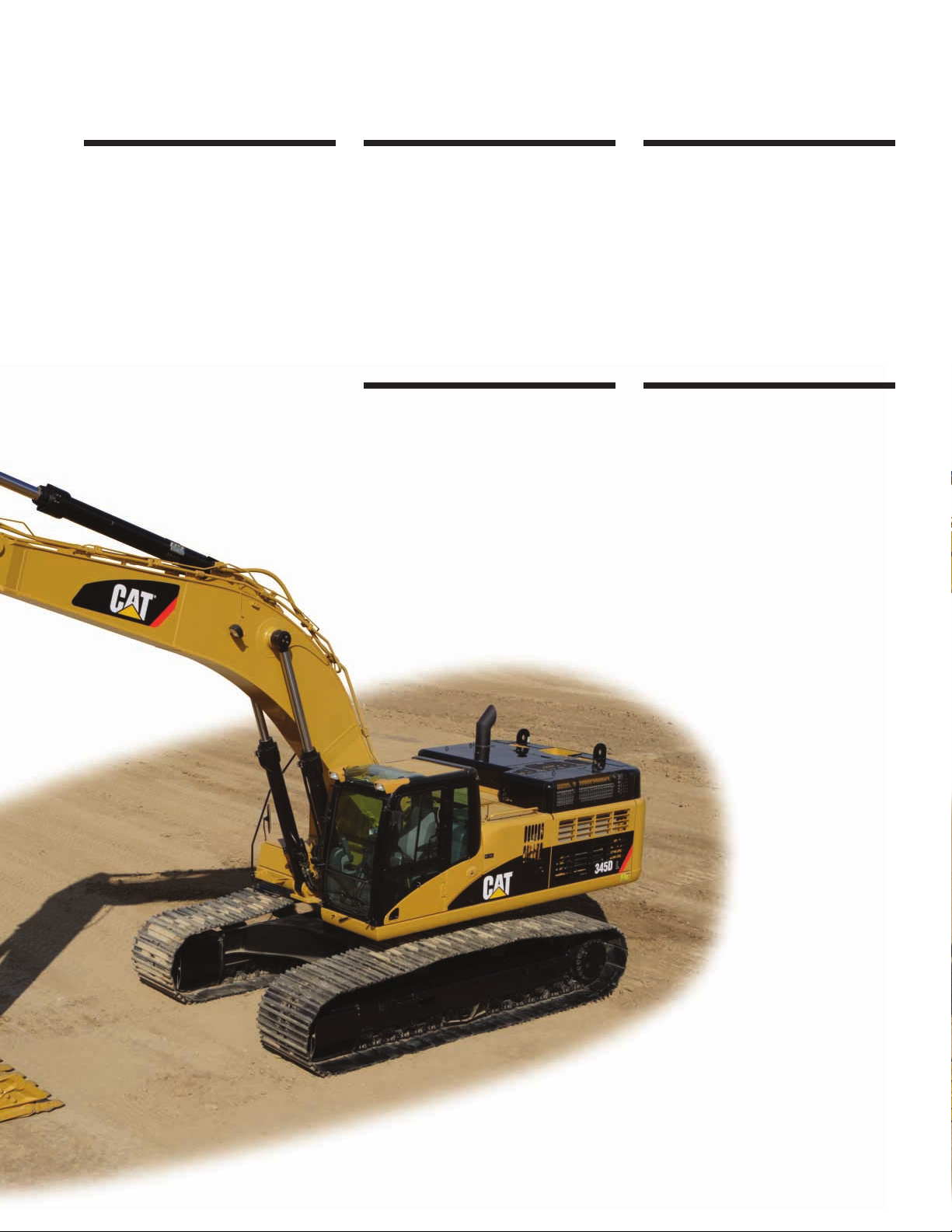
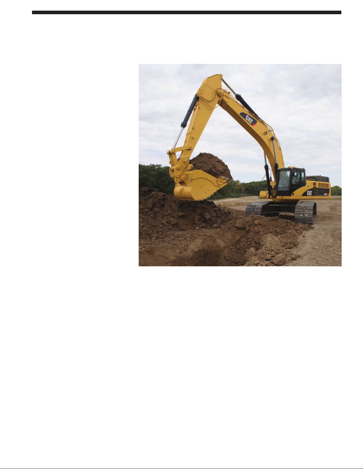
345D L Hydraulic Excavator
The 345D L hydraulic excavator’s high performance and rugged durability combine
to maximize your productivity.
Outstanding performance. Excellent control,
high stick and bucket forces, impressive lift
capacity, simplified service and a comfortable
operator station to increase your productivity
and lower operating costs.
Versatility
Caterpillar offers a wide variety of
optional and factory-installed attachments
to enhance performance and improve
job site management. pg. 12
Work Tools
A variety of work tools, including
buckets, couplers, hammers, and shears
are available through Cat®Work Tools.
pg. 11
Complete Customer Support
Your Cat dealer offers a wide range
of services – from assistance with
configuring your machine to best match
your application to customer support
agreements to meet your maintenance
needs. Repair Option Programs
guarantee the cost of repairs up front
and help you to avoid unscheduled
repairs. pg. 15
Operator Station
Provides maximum space, excellent
visibility and easy access to all
switches. The monitor is a full-color
graphical display that allows the
operator to understand the machine
information easily. Overall, the cab
provides a comfortable environment
for the operator. pg. 6
Hydraulics
The hydraulic system has been designed
to provide reliability and outstanding
controllability. An optional Tool Control
System provides enhanced flexibility.
pg. 5
C13 Engine with ACERT™ Technology
ACERT™ Technology works at the
point of combustion to optimize engine
performance and provide low exhaust
emissions to meet U.S. EPA Tier 3 and
EU Stage IIIA emission regulations, with
exceptional performance capabilities
and proven reliability. pg. 4
Page 3
3
Service and Maintenance
Fast, easy service has been designed
in with extended service intervals,
advanced filtration, convenient filter
access and user-friendly electronic
diagnostics for increased productivity
and reduced maintenance costs. pg. 14
AccuGrade™ Grade Control System
for Hydraulic Excavators
The AccuGrade System helps to move
material right the first time, reduces
costs and increases material utilization.
The system improves operator skills,
helping with labor requirements and
improves safety on the job site. pg. 13
Boom, Sticks and Attachments
Built for good performance and long
service life, Cat booms and sticks are
box-section structures with thick multiplate fabrications to resist high stress.
Three lengths of booms and five types
of sticks are available, offering a range
of configurations suitable for a wide
variety of applications and conditions.
pg. 10
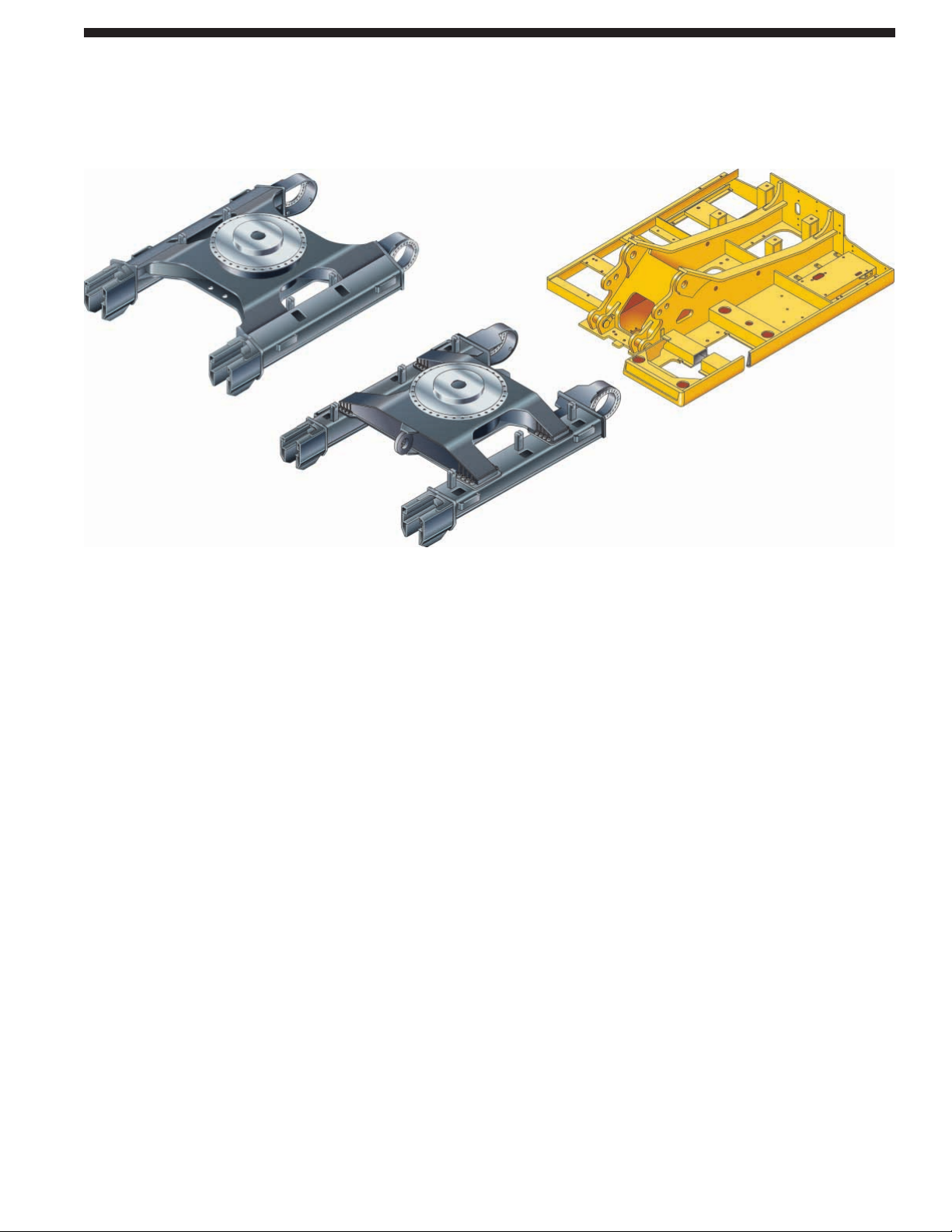
Structures
Caterpillar®design and manufacturing
techniques assure outstanding durability
and service life from these important
components. pg. 9
Undercarriage
Cat designed excavator undercarriage
is stable, durable and low maintenance.
Available in Fixed, Variable and Wide
Variable gauge configurations to meet
lift capacity and bucket size needs. pg. 8
Page 4
Performance. The 345D L, equipped
with the C13 with ACERT Technology,
meets the U.S. EPA Tier 3 emissions
while providing 10% more horsepower
compared to the 345C L. The building
blocks of ACERT Technology are fuel
delivery, air management, and electronic
control – providing better fuel economy
and reduced wear.
Emissions. ACERT Technology is a
differentiated technology that reduces
emissions at the point of combustion.
The technology capitalizes on
Caterpillar’s proven leadership
in three core engine systems: fuel,
air and electronics.
Fuel System. The Cat C13 features
electronic controls that govern the
mechanically actuated unit fuel injection
(MEUI) system. MEUI provides the
high-pressure required to help reduce
particulate emissions and deliver
better fuel economy through finer
fuel atomization and more complete
combustion.
Controllers. The mechanically actuated
unit injection system features a highpressure fuel injection system, proven
to significantly reduce fuel consumption
and particulate emission. Electronic Unit
Injection (EUI) produces high-pressure
and affords the integration of electronics
with fewer components. The modular
design of the electronic control system
allows greater update, flexibility,
improves serviceability and lowers
repair costs.
ADEM™ A4 Engine Controller.
The ADEM™ A4 electronic control
module manages fuel delivery to get
the best performance per liter or gallon
of fuel used. The engine management
system provides flexible fuel mapping,
allowing the engine to respond quickly
to varying application needs. It tracks
engine and machine conditions while
keeping the engine operating at peak
efficiency.
Turbocharger. The Cat C13 uses a
wastegate turbocharger for improved
performance.
• The wastegate valve controls
excessive engine boost pressure
by allowing exhaust to bypass the
exhaust-side turbine.
• The wastegate also reduces turbine
wear in high RPM, low load conditions
and optimizes air and fuel delivery
for peak engine performance.
• The turbocharger increases the density
of the air, enabling the engine to
produce more power with few
effects from altitude.
Low Sound and Vibration Levels.
The engine mounts are rubber-isolating
mounts matched with the engine package
to provide optimum sound and vibration
reduction. Further noise reduction has
been achieved through design changes
to the isolated top cover, oil pan,
multiple injection strategy, insulated
timing cover and sculpted crankcase.
Air Cleaner. The radial seal air filter
features a double-layered filter core for
more efficient filtration and is located in
a compartment behind the cab. A warning
is displayed on the monitor when dust
accumulates above a preset level.
Cooling System. The 345D L layout
completely separates the cooling
system from the engine compartment.
The cooling fan is hydraulically driven
with variable speed control based
on the ambient temperature, coolant
temperature, and hydraulic oil
temperature. This unique feature
assists in the management of engine
power and improves noise efficiency
while providing optimized cooling.
Cold Weather Starting Kit. The optional
kit includes two additional batteries,
heavy-duty battery cables, and the ether
starting aid. With this kit, the 345D L
has the capability to start at –32° C
(–25.6° F).
4
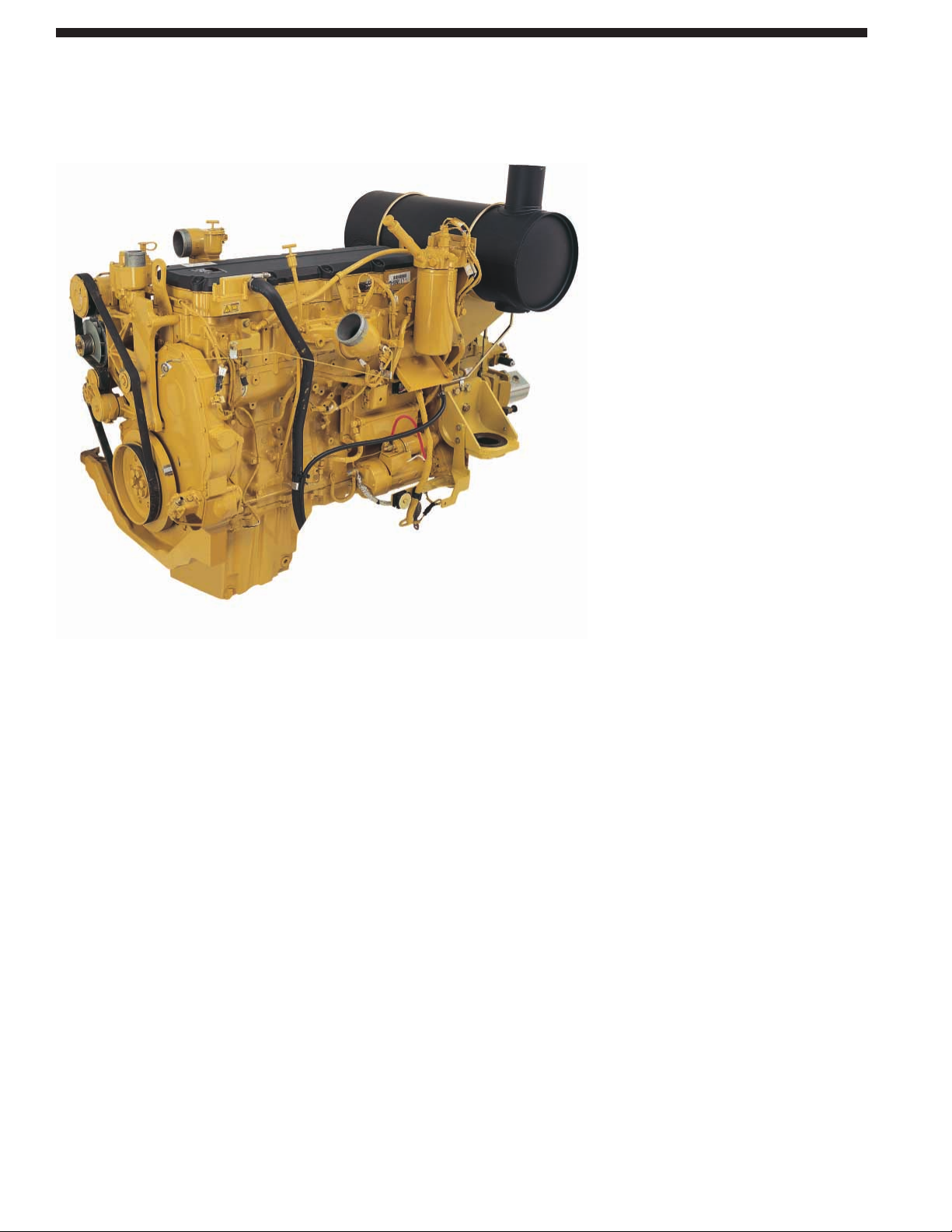
C13 Engine with ACERT™ Technology
Built for power, reliability, economy and low emissions.
Page 5
Pilot System. The pilot pump is
independent from the main pumps
and controls the front linkage, swing
and travel operations. The pilot control
valve operation is proportional to control
lever movement, delivering outstanding
controllability.
Component Layout. The component
location and hydraulic system design
provide the highest level of system
efficiency. The main pumps, control
valve and hydraulic tank are located
as close to each other as possible.
This design makes it possible to
use shorter tubes and lines between
components, reducing friction losses
and pressure drops.
Heavy Lift Standard. The operator can
select the heavy lift mode at the push
of a button to boost lifting capability
and provide improved controllability
of heavy loads.
Hydraulic Cross-Sensing System.
The hydraulic cross sensing system
utilizes each of two hydraulic pumps
to 100 percent of engine power under
all operating conditions. This improves
productivity with faster implement
speeds and quicker, stronger pivot turns.
Boom and Stick Regeneration Circuits.
A hydraulically operated stick
regeneration circuit saves energy and
improves multi-function performance
during the stick-in operation. New on
the 345D L, the boom regeneration
circuit is operated electrically, and this
system is managed by the machine ECM.
The system improves cycle times and fuel
efficiency, increasing your productivity
and reducing operating costs.
Boom and Swing Priority. The hydraulic
system on the 345D L provides automatic
priority function for boom-up and swing
operations eliminating the need for
work mode buttons. When the boom
or swing lever is activated, the system
automatically assigns priority based
on operator demand.
Hydraulic Cylinder Snubbers.
Snubbers are located at the rod-end
of the boom cylinders and both ends
of the stick cylinders to cushion shocks
while reducing sound levels and
extending component life.
5
Hydraulics
Cat®hydraulics deliver power and precise control to keep material moving.
Page 6
6
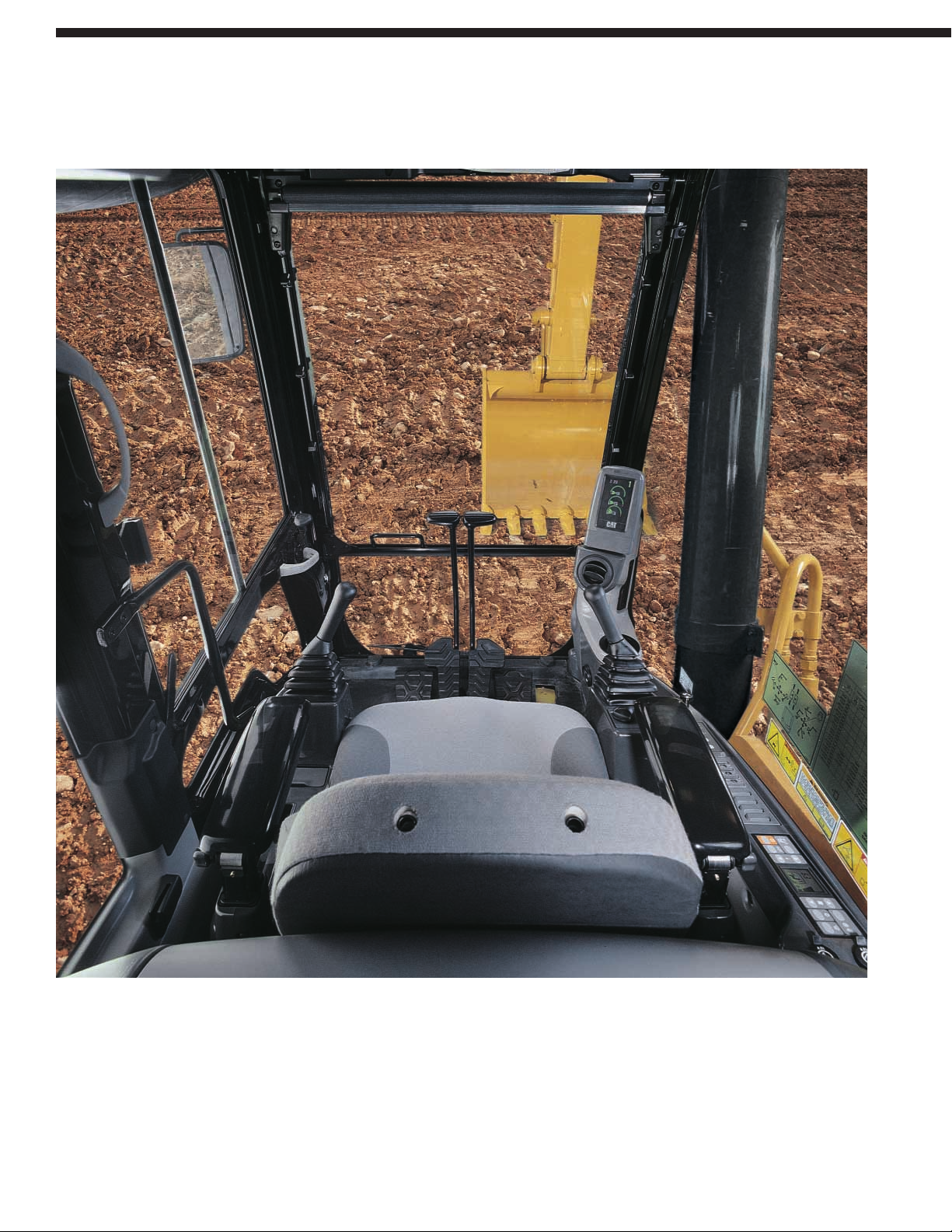
Designed for simple, easy operation, the 345D L allows the operator to focus on production.
Operator Station
Page 7
Cab Design. The workstation is spacious,
quiet and comfortable, assuring high
productivity during a long work day.
The air conditioner and attachment
switches are conveniently located on
the right-hand wall, and the key switch
and throttle dial are on the right-hand
console. The monitor is easy to see
with excellent visibility.
Standard Cab Equipment. To enhance
operator comfort and productivity, the
cab includes a lighter, drink holder, coat
hook, service meter, literature holder,
magazine rack and storage compartment.
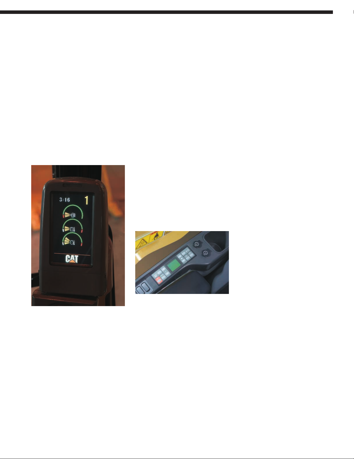
Monitor Display Screen. The compact,
full color 400x234 pixels Liquid Crystal
Display (LCD), displays machine
maintenance, diagnostic and prognostic
information, in twenty-seven different
languages. The keypad allows the
operator to select machine operation
conditions and to set view preferences.
The Master Caution Lamp blinks ON
and OFF when one of these critical
conditions occur:
• Engine oil pressure low
• Coolant temperature high
• Hydraulic oil temperature high
Under the normal condition or the
default condition, the monitor display
screen is divided into four areas: clock
and throttle dial area, gauge area, event
display area and multi-information
display area.
Clock and Throttle Dial Area. The clock,
throttle dial position and green gas-station
icon are displayed on the monitor screen.
Gauge Area. Three analog gauges, fuel
level, hydraulic oil temperature and
coolant temperature, are displayed
on the monitor screen.
Event Display Area. Machine information
is displayed on the monitor screen with
the icon and language.
Multi-information Display Area.
This area is reserved for displaying
information that is convenient for the
operator. The “CAT” logo is displayed
when no information is available to
be displayed.
Console. The consoles feature a simple,
functional design to reduce operator
fatigue, ease of switch operation and
excellent visibility. Both consoles have
attached armrests with height adjustments.
Travel Controls. The 345D L uses pilot
operated control levers, positioned so the
operator can operate with arms on the
armrests. The vertical stroke is longer
than the horizontal stroke, reducing
operator fatigue. The control lever grips
are shaped to fit into the operator’s
hands. The horn switch and one-touch
low idle switch are positioned on the
left and right grip.
Hydraulic Activation Control Lever.
For added safety, this lever must be
in the operate position to activate the
machine control functions.
Seat. A high-back, heated, air-suspension
seat is now standard on the 345D L.
The seat allows a variety of adjustments
to suit the operator’s size and weight
and provides a comfortable working
environment. Wide adjustable armrests
and a retractable seatbelt are also included.
Climate Control. Positive filtered
ventilation with a pressurized cab comes
standard on the 345D L. Fresh air or
re-circulated air can be selected with
a switch on the left console.
Cab Exterior. The exterior design uses
thick steel tubing along the bottom
perimeter of the cab, improving the
resistance of fatigue and vibration.
This design allows the FOGS to be
bolted directly to the cab, at the factory
or as an attachment later, enabling the
machine to meet specifications and
job site requirements.
Cab Mounts. The cab shell is attached
to the frame with viscous rubber cab
mounts, which dampen vibrations and
sound levels while enhancing operator
comfort.
Windows. All glass is affixed directly
to the cab, eliminating window frames
and providing excellent visibility.
The upper front windshield opens,
closes and stores on the roof above
the operator with a one-touch action
release system.
Wipers. Pillar-mounted wipers increase
the operator’s viewing area and offer
continuous and intermittent modes.
Skylight. An enlarged skylight with
sunshade provides excellent visibility
and good ventilation.
7
Page 8
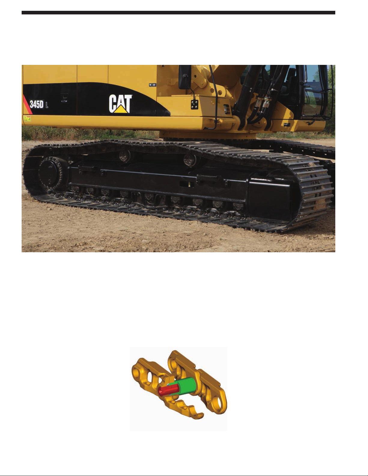
Undercarriage Options. Track with
Positive Pin Retention 2 (PPR2) and
cast idlers are available as attachments
on the 345D L. The PPR2 prevents
loosening of the track pin from the track
link and the cast idler is designed for
extended life. Both options are ideal for
extreme applications or those that require
a large amount of travel.
Travel Motors. Two-speed axial piston
hydraulic motors provide the 345D L
drive power and speed selection.
When the high-speed position is
selected, the machine automatically
changes between computer-controlled
high and low speeds depending on
drawbar-pull requirements.
Straight-line Travel Circuit. The straightline travel circuit is incorporated into
the hydraulic system, which maintains
low-speed, straight-line travel, even
when operating the front linkage.
Final Drive. The final drives are a threestage planetary reduction. This design
results in a complete drive/brake unit
that is compact and delivers excellent
performance and reliability.
Track. The 345D L comes standard with
a grease lubricated track called GLT4.
The track links are assembled and sealed
with grease to decrease internal bushing
wear, reduce travel noise, and lower
operating costs by extending service life.
The track link for the 345D L has been
re-designed to avoid the concentration
of stresses and improve durability
and reliability.
Track Guards. The idler guard and
bolt-on center guard are standard
equipment. They help maintain track
alignment while traveling or working
on slopes. For applications that require
additional track protection or alignment,
optional guards are available.
8
Undercarriage
Durable undercarriage absorbs stresses and provides excellent stability.
Page 9
Carbody. The 345D L has three
undercarriage options to meet regional
transportation requirements and
application needs.
• Fixed gauge for narrow transport
and weight sensitive areas.
• Variable gauge for increased
track and ground clearance and
over-side lift.
• Wide variable gauge, provided as
an attachment to the variable gauge
machine, provides a significant
increase in over-side lift with the
capability for handling larger buckets.
The carbody utilizes a columnless
design that allows the swing bearing
to be directly mounted on the top plate
for excellent rigidity and strength.
Upper Frame. The rugged main frame
is designed for maximum durability.
Robot welding is used for consistent,
high-quality welds. The main channels
are box sections connected by a large
diameter tube in the boom foot area to
improve rigidity and strength. The outer
frame utilizes curved side rails for rigidity
against bending and torsional loads.
Counterweights. The 345D L has
several counterweight options to best
match the machine to your application.
Counterweight removal device is
available for the 7.6 mt (16,760 lb)
and 8.7 mt (19,180 lb) counterweights
to facilitate transport when needed.
Track Roller Frame. Fixed Gauge
Undercarriage
• Uses a press-formed, pentagonal
section for the track frame that is
robot-welded for weld consistency
and quality. The track frame has
been designed so that the top of
the track frame has a steep angle
to help prevent accumulation
of mud and debris.
Variable Gauge Undercarriage
• The track roller frame is made of
thick steel plate that is bent into a
U shape and welded to the bottom
plate to create a box structure.
The box structure design increases
rigidity and impact resistance.
9
Structures
The 345D L structural components are the backbone of the machine’s durability.
Page 10
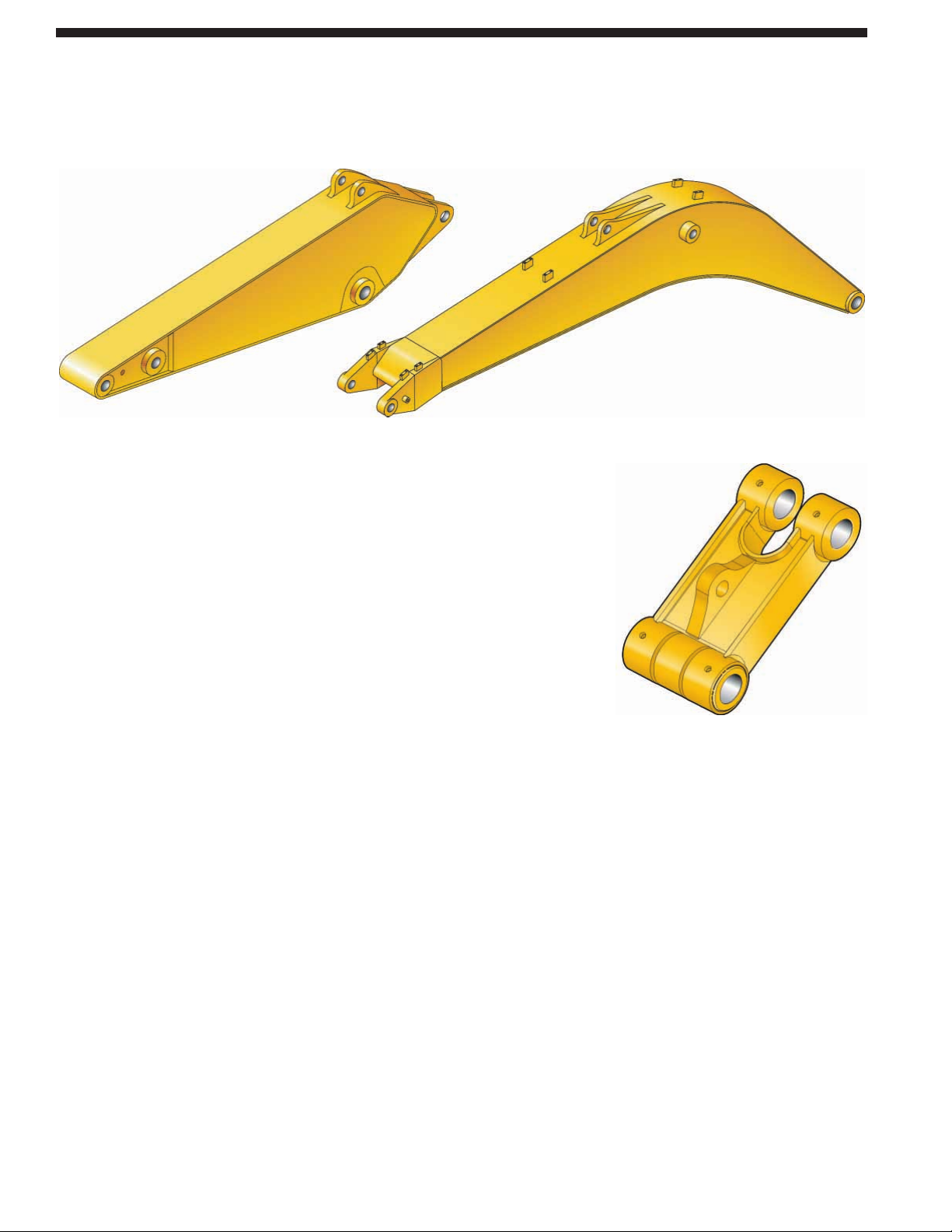
Front Linkage Attachments.
Three length of booms and five types
of sticks are available, offering a range
of configurations suitable for a wide
variety of application conditions.
Boom Construction. The 345D L booms
have large cross-sections and internal
baffle plates to provide long life and
durability. Forged steel is used in critical
high-load areas such as the boom-foot
and boom cylinder connection.
Long Reach Boom – 7.4 m (23'3") long.
The Long Reach boom, when combined
with the 4.3 m (14'1") stick, provides a
similar digging envelope to the previous
345C. This boom/stick combination has
a significantly reduced transport height,
eliminating the need to remove the stick
cylinder pin.
HD Reach Boom – 6.9 m (22'8") long.
The Heavy Duty (HD) Reach boom is
designed to balance reach, digging force
and bucket capacity, making it ideal for
a wide range of applications.
Mass Excavation Boom – 6.55 m (21'6")
long. The mass boom is designed to
provide maximum digging forces, bucket
capacity and truck loading productivity.
The mass boom comes with two stick
options for further job site versatility.
Stick Construction. The 345D L sticks
are made of high-tensile strength steel,
using a large box section design,
interior baffle plates and an additional
bottom guard.
Power Link. The 345D L power link
improves durability, increases machinelifting capability in key lifting positions,
and is easier to use compared to the
previous lift bar designs.
10
Boom, Sticks and Attachments
Designed for maximum flexibility to keep productivity and efficiency high on all jobs.
Page 11
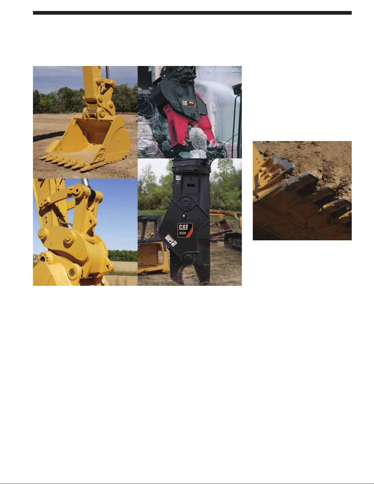
Work Tools. Choose from a variety
of work tools such as hammers, shears,
pulverizers, compactors, multi-processors,
sorting grapples and couplers. Ask your
Cat dealer for information on
attachments or special configurations.
General Purpose Buckets. General
purpose (GP) buckets are best suited
for digging in low-impact, moderately
abrasive materials such as dirt, loam,
gravel and clay.
Heavy Duty Buckets. Heavy duty (HD)
buckets are designed for a wide range
of moderately abrasive applications such
as mixed dirt, clay and rock. HD buckets
have optimized loading and dumping
characteristics and more robust
construction than the GP buckets.
Heavy-Duty Power Buckets.
Heavy duty
power (HDP) buckets are for use in
moderately abrasive applications where
breakout force and cycle times are
critical. Decreased tip radius maximizes
tip force and improves cycle times in
most materials. Not ideal for use in sticky
material conditions. Cutting edge and
GET are up-sized.
Heavy Duty Rock Buckets. Heavy duty
rock (HDR) buckets are designed for
aggressive bucket loading in highly
abrasive applications such as shot rock
and granite. Features include:
• Thick wear plates to extend the life
of the bucket in severe applications.
• Side wear plates that extend further up
the side of the bucket for maximum
protection in rocky soils.
• Sidebar protectors are available for
sidebar protection, or side-cutters
can be used to provide increased
fill characteristics and bucket
wear protection.
Rock Ripping Buckets. Rock ripping
(RR) buckets are ruggedly constructed,
narrow buckets for ripping in applications
where material penetration and an inability
to blast is an issue. The aggressive liptype ripping design uses five sharp or
twin sharp teeth in a staggered position.
The staggered design allows one or two
tips to penetrate first, providing higher
breakout forces.
Caterpillar Ground Engaging Tools (GET).
Caterpillar K Series™ GET is featured
on the 345D L buckets. The K Series™
system uses a vertical retainer, which is
easier to remove and install than the old
Cat J Series pin. There are a variety of
teeth, side cutters, and sidebar protectors
to match operating conditions.
• The teeth are designed to be
extremely aggressive and offer
excellent penetration.
• The side-cutter design is aggressive
in trenching applications, improving
efficiency and bucket payload.
Service Life. Caterpillar
®
buckets increase
service life and reduce repair costs.
• Dual radius design for increased life
and reduced wear.
• Robot welding of hinge assembly
for increased weld penetration and
longer life.
• Incorporates the aggressive and easier
to install K Series™ GET system.
• High strength and heat-treated steel
that exceeds T-1 in high wear areas.
11
Work Tools
The 345D L has an extensive selection of work tools to optimize machine performance.
Page 12

Tool Control System. The optional
tool control system maximizes work
tool productivity by configuring
hydraulic flow, pressure, and operator
controls to match a specific work tool.
System versatility enables a wide
range of tools to be used.
Auxiliary Hydraulic Valve. A hydraulically
controlled auxiliary valve is standard on
the 345D L. Control circuits are available
as attachments, allowing operation of
high and medium pressure tools such as
shears, grapples, hammers, pulverizers,
multi-processors and vibratory plate
compactors.
Product Link. Product Link 321 is now
standard on the 345D L. The optional
levels of service, including Asset Watch,
Maintenance Watch, and Health Watch
allow you to monitor and maintain your
equipment for the lowest operating cost.
Control Levers. Three types of tool
controls are available to meet the
operator’s individual preference.
• Foot Pedal – The hydraulic modulated
foot pedal is used in conjunction
with the hydraulic controller.
• Foot Switch – The electric on/off
switch pedal is used in conjunction
with either the hydraulic controller
or attachment controller. The foot
switch is located on cab floor.
• Tool Controller Joystick – Two
types of the tool controller joysticks
are available. The joystick with the
modulation switch has two on/off
switches, one trigger switch and
one modulation switch. The joystick
without the modulation switch has
three on/off switches and one
trigger switch.
Machine Security. An optional Machine
Security System is available from the
factory on the 345D L. This system
controls when the machine can be
operated and utilizes specific keys
to prevent unauthorized machine use,
a significant theft deterrent.
12
Versatility
A wide variety of optional and factory-installed attachments are available to enhance
performance and improve job site management.
Page 13

13
AccuGrade™ Grade Control System for Hydraulic Excavators
The AccuGrade Excavator System design integrates the scalable machine control
and guidance system to optimize performance, reliability and productivity.
Overview. The AccuGrade System for
Hydraulic Excavators reduces guesswork
and costly rework by moving material
right the first time, reduces survey
costs up to 90%, and increases material
utilization. The system improves operator
skills, which reduces labor requirements,
aids operators in maintaining a consistent
grade and slope across the worksite,
and reduces material cost.
The AccuGrade Attachment Ready Option
(ARO) Machine. The ARO supports all
kits and integrates the critical sensors
with the machine right out of the factory.
The design uses advanced Position
Sensing Cylinder (PSC) technology
as well as heavy duty rotary sensors.
With the PSC, the AccuGrade system
determines the current cylinder length
and the current position of the bucket
tip in real time.
The PSC also removes the front linkage
sensors from the traditional high wear
areas such as the bucket linkage, and
places them safely inside the bucket
cylinder for increased integration,
responsiveness, and reliability.
The ARO uses a Controller Area Network
(CAN) designed for plug-and-play
capability. Simply mount the components,
connect, calibrate and the system is ready
to operate. All wiring and necessary
welded brackets are factory installed
as part of the ARO.
AccuGrade Site Reference Kit.
The AccuGrade Site Reference system
provides the operator with precise, realtime bucket positioning relative to the
desired grade. Using a combination of
sensors, the system calculates bucket tip
position relative to a grade/survey stake
or benchmark.
AccuGrade Laser Reference Kit.
The optional system allows the machine
to move after obtaining a reference
benchmark. The laser receiver attachment
references a rotating laser to calculate
the desired grade for elevation changes
over large work sites, significantly
increasing productivity.
AccuGrade GPS Kit. AccuGrade GPS
uses 3D design files that are stored on the
in-cab display and is able to use satellites
in both the US and the GLONASS
satellite constellation to augment the
GPS solution and define the location
of the machine on the job site. With the
addition of the machine position to the
location of the bucket determined by
the machine-mounted components,
AccuGrade GPS then compares the
position of the bucket relative to the
site design plan and delivers real-time
information to the operator.
Applications. The Site and Laser
Reference systems are ideal for building
pads, trenches, and general utility
applications. The 3D system is ideal
for all applications, including finishing
slopes, excavating and truck loading,
complex trenches, and sites with
3D designs, such as retention ponds
and golf courses.
Page 14

14
Extended Service Intervals.
Extended service and maintenance
intervals increase machine availability.
The maintenance intervals for engine
oil and engine oil filter have been
extended to 500 hours.
Capsule Filter. The hydraulic return
filters are located in the hydraulic tank.
The filter elements are removable
without spilling hydraulic oil.
Pilot Hydraulic System Filter.
The pilot hydraulic system filter keeps
contaminants from the pilot system and
is located in the pump compartment.
Radial Seal Main Air Cleaner. The radial
seal main air cleaner with pre-cleaner
has a double-layered filter element for
more efficient filtration. No tools are
required to change the element.
Fuel-Water Separator. The water
separator has a primary fuel filter
element and is located in the battery
compartment for easy access from
the ground.
Service Points. Service points are
centrally located with easy access to
facilitate routine maintenance.
Oil Sample and Pressure Ports.
Oil sample and pressure ports provide
easy checking of machine condition
and are standard on every machine.
Greasing Points. A concentrated remote
greasing block on the boom delivers
grease to hard-to-reach locations.
Service and Maintenance
Simplified service and maintenance save you time and money.
Page 15

15
Product Support. You will find nearly
all parts at our dealer parts counter.
Cat dealers utilize a worldwide computer
network to find in-stock parts to minimize
machine downtime. You can save money
with Cat remanufactured components.
Machine Selection. Make detailed
comparisons of the machines you are
considering before you buy. What are the
job requirements, machine attachments
and operating hours? What production
is needed? Your Cat dealer can provide
recommendations.
Purchase. Look past initial price.
Consider the financing options available
as well as day-to-day operating costs.
This is also the time to look at dealer
services that can be included in the cost
of the machine to yield lower equipment
owning and operating costs over the
long run.
Customer Support Agreements.
Cat dealers offer a variety of product
support agreements, and work with
customers to develop a plan that best
meets specific needs. These plans can
cover the entire machine, including
attachments, to help protect your
investment.
Operation. Improving operating
techniques can boost your profits.
Your Cat dealer has videotapes, literature
and other ideas to help you increase
productivity, and Caterpillar offers
certified operator training classes to
help maximize the return on your
investment.
Maintenance Services. Repair option
programs guarantee the cost of repairs
up front. Diagnostic programs such as
Scheduled Oil Sampling, Coolant
Sampling and Technical Analysis help
you avoid unscheduled repairs.
Replacement. Repair, rebuild or replace?
Your Cat Dealer can help you evaluate
the cost involved so you can make the
right choice.
SAFETY.CAT.COM™.
Complete Customer Support
Cat dealer services help you operate longer with lower costs.
Page 16

16
345D L Hydraulic Excavator specifications
Hydraulic System
Main System – 734 L/min 194 gal/min
Maximum Flow (Total)
Maximum Pressure – 35 000 kPa 5,080 psi
Equipment – Normal
Maximum Pressure – 38 000 kPa 5,511 psi
Equipment – Heavy Lift
Maximum Pressure – Travel 35 000 kPa 5,080 psi
Maximum Pressure – Swing 31 400 kPa 4,550 psi
Pilot System – Maximum flow 43 L/min 11 gal/min
Pilot System – Maximum pressure 4110 kPa 596 psi
Boom Cylinder – Bore 160 mm 6.3 in
Boom Cylinder – Stroke 1575 mm 62 in
Stick Cylinder – Bore 190 mm 7.5 in
Stick Cylinder – Stroke 1778 mm 70 in
(for Long Reach and Reach fronts)
Stick Cylinder – Stroke 1758 mm 69.2 in
(for mass excavation fronts)
TB Family Bucket Cylinder – Bore 160 mm 6.3 in
TB Family Bucket Cylinder – Stroke 1356 mm 53.4 in
UB Family Bucket Cylinder – Bore 170 mm 6.7 in
UB Family Bucket Cylinder – Stroke 1396 mm 55 in
Main normal relief pressure 35 000 kPa 5,080 psi
Sound Performance
Performance ANSI/SAE J1166 MAY90
Meets OSHA and MSHA
Requirements
• When properly installed and maintained, the cab offered
by Caterpillar, when tested with doors and windows closed
according to ANSI/SAE J1166 OCT 98, meets OSHA and
MSHA requirements for operator sound exposure limits
in effects at time of manufacture.
• Hearing protection may be needed when operating with
an open operator station and cab (when not properly
maintained or doors/windows open) for extended periods
or in noisy environment.
Standards
Brakes SAE J1026 APR90
Cab/FOGS SAE J1356 FEB 88 and
ISO 10262-1998
Engine
Engine Model Cat C13 ACERT
Net Flywheel Power 283 kW 380 hp
Net Power – ISO 9249 283 kW 380 hp
Net Power – SAE J1349 283 kW 380 hp
Net Power – EEC 80/1269 283 kW 380 hp
Bore 130 mm 5.1 in
Stroke 157 mm 6.2 in
Displacement 12.5 L 763 in
3
Cylinders 6
• The 345D L meets U.S. EPA Tier 3 and EU Stage IIIA exhaust
emission requirements.
• Net power advertised is the power available at the flywheel
when the engine is equipped with fan, air cleaner, muffler
and alternator.
• No engine derating needed up to 2300 m (7,500 ft).
Weights
Operating Weight – 45 375 kg 100,040 lb
Long Undercarriage
Operating Weight – 49 265 kg 108,610 lb
Long Variable
• 6.9 m (22'8") HD Reach Boom, R3.9m (12'10") Stick,
1219 mm (48") GP-C Bucket, 750 mm (30") TG Track Shoes,
Long Undercarriage
Swing Mechanism
Swing Speed 8.7 rpm
Swing Torque 148.5 kN·m 109,560 lb ft
Drive
Maximum Travel Speed 4.5 km/h 2.8 mph
Maximum Drawbar Pull – 337.7 kN 75,920 lb
Long Undercarriage
Service Refill Capacities
Fuel Tank Capacity 705 L 186 gal
Cooling System 35.5 L 9.4 gal
Engine Oil 42 L 11 gal
Swing Drive (each) 10 L 2.6 gal
Final Drive (each) 15 L 4 gal
Hydraulic System (including tank) 570 L 150 gal
Hydraulic Tank 243 L 64 gal
Page 17

17
345D L Hydraulic Excavator specifications
Dimensions
All dimensions are approximate.
3
9
6
7
8
1
10
4
5
2
Boom Long Reach Boom HD Reach Boom Mass Boom
7.4 m (24'3") 6.9 m (22'8") 6.55 m (21'6")
Stick R4.3TB R3.9TB R3.9TB R3.35TB M3.0UB M2.5UB
(14'1") (12'10") (12'10") (11'0") (9'10") (8'2")
1 Shipping Height
Fixed Gauge 3680 mm 3570 mm 3660 mm 3690 mm 4020 mm 3960 mm
Undercarriage (12'1") (11'8") (12'0") (12'1") (13'2") (13'0")
Variable Gauge 3630 mm 3550 mm 3640 mm 3720 mm 4050 mm 4000 mm
Undercarriage (11'11") (11'7") (11'11") (12'2") (13'3") (13'2")
2 Shipping Length
Fixed Gauge 12 450 mm 12 430 mm 11 950 mm 11 940 mm 11 640 mm 11 710 mm
Undercarriage (40'10") (40'9") (39'2") (39'2") (38'2") (38'5")
Variable Gauge 12 400 mm 12 370 mm 11 910 mm 11 910 mm 11 620 mm 11 680 mm
Undercarriage (40'8") (40'7") (39'1") (39'1") (38'1") (38'4")
3 Tail Swing Radius 3770 mm 3770 mm 3770 mm 3770 mm 3770 mm 3770 mm
(12'4") (12'4") (12'4") (12'4") (12'4") (12'4")
Undercarriage Fixed Gauge Variable Gauge Wide Variable Gauge
4 Length to Center of Rollers 4360 mm (14'4") 4340 mm (14'3") 4340 mm (14'3")
5 Track Length 5360 mm (17'7") 5340 mm (17'6") 5340 mm (17'6")
6 Ground Clearance 510 mm (1'8") 740 mm (2'5") 740 mm (2'5")
7 Track Gauge
Retracted (Transport) Position 2740 mm (9'0") 2640 mm (8'8") 2760 mm (9'1")
Extended (Working) Position 2740 mm (9'0") 2890 mm (9'6") 3240 mm (10'8")
8 Track Width*
Retracted (Transport) Position 3640 mm (11'11") 3540 mm (11'7") 3660 mm (12'0")
Extended (Working) Position 3640 mm (11'11") 3790 mm (12'5") 4140 mm (13'7")
9 Cab Height 3210 mm (10'6") 3360 mm (11'0") 3360 mm (11'0")
10 Counterweight Height (to bottom) 1320 mm (4'4") 1470 mm (4'10") 1470 mm (4'10")
* Track width shown is for 900 mm (36") track shoes. Subtract 150 mm (6") for 750 mm (30") track shoes.
Page 18

18
345D L Hydraulic Excavator specifications
HD Reach Working Ranges
Heavy Duty (HD) Reach boom configuration
Mass Working Ranges
Mass (M) boom configuration
Meters
Feet
12
40
11
35
10
9
9
30
8
8
25
7
7
6
6
20
5
5
15
4
4
10
10
15
20
25
30
3
3
2
5
1
0
0
1
5
2
3
6
1
4
5
6
7
8
9
121315 10 911
14
16
50
4
2
5
87654
35 304045 25 20 15 10 5 -50
3210 -2-3-1
R3.35TB
R3.9TB
R3.9TB
R4.3TB
Meters
Feet
Meters
Feet
12
40
11
35
10
9
9
30
8
8
25
7
7
6
6
20
5
5
15
4
4
10
10
15
20
25
30
3
3
2
5
1
0
0
1
5
2
6
3
1
4
5
6
7
8
9
121315 10 911
14
16
50
4
2
5
87654
35 304045 25 20 15 10 5 -50
3 2 1 0 -2 -3-1
M2.5UB
M3.0UB
Meters
Feet
345D L Working Ranges – Long Fixed Gauge Undercarriage
Long Reach Boom HD Reach Boom Mass Excavation Boom
Stick R4.3TB R3.9TB R3.9TB R3.35TB M3.0UB M2.5UB
(14'1") (12'10") (12'10") (11'0") (9'10") (8'2")
Bucket GP-C 1.8 m3GP-C 1.8 m3GP-C 1.8 m3GP-C 1.8 m3HD 3.11 m
3
HD 3.11 m
GP-C 2.36 yd3GP-C 2.36 yd3GP-C 2.36 yd3GP-C 2.36 yd3HD 4.07 yd3HD 4.07 yd
1 Maximum Digging Depth 8920 mm 8520 mm 8200 mm 7650 mm 7200 mm 6700 mm
(29'3") (27'11") (26'11") (25'1") (23'7") (22'0")
2 Maximum Reach at 12 940 mm 12 580 mm 12 120 mm 11 710 mm 11 160 mm 10 700 mm
Ground Level (42'5") (41'3") (39'9") (38'5") (36'7") (35'1")
3 Maximum Loading Height 7870 mm 7750 mm 7410 mm 7420 mm 6830 mm 6640 mm
(25'10") (25'5") (24'4") (24'4") (22'5") (21'9")
4 Minimum Loading Height 2240 mm 2640 mm 2200 mm 2750 mm 2670 mm 3170 mm
(7'4") (8'8") (7'3") (9'0") (8'10") (10'5")
5 Maximum Depth Cut for 8790 mm 8380 mm 8070 mm 7500 mm 7050 mm 6530 mm
2440 mm (8') Level Bottom (28'10") (27'6") (26'6") (24'7") (23'1") (21'5")
6 Maximum Vertical Wall 5860 mm 5330 mm 5300 mm 5210 mm 4660 mm 4220 mm
Digging Depth (19'3") (17'6") (17'4") (17'1") (15'3") (13'10")
3
3
345D L Working Ranges with Pin Grabber Coupler – Long Fixed Gauge Undercarriage
HD Reach Boom
Stick R3.35TB (11'0")
Bucket with UB-Family Coupler GP-C 1.8 m
GP-C 2.36 yd
3
3
1 Maximum Digging Depth 8010 mm (26'4")
2 Maximum Reach at Ground Level 12 070 mm (39'7")
3 Maximum Loading Height 7060 mm (23'1")
4 Minimum Loading Height 2400 mm (7'11")
5 Maximum Depth Cut for 2440 mm (8') Level Bottom 7870 mm (25'10")
6 Maximum Vertical Wall Digging Depth 4010 mm (13'2")
Page 19

19
345D L Hydraulic Excavator specifications
HD Reach Working Ranges
Heavy Duty (HD) Reach boom configuration
Mass Working Ranges
Mass (M) boom configuration
Meters
Feet
12
40
11
35
10
9
9
30
8
8
25
7
7
6
6
20
5
5
15
4
4
10
3
2
5
1
0
0
1
5
2
10
3
4
15
5
20
6
7
25
8
30
9
14
16
50
121315 10 911
87654
35 304045 25 20 15 10 5 -50
3210 -2-3-1
R3.35TB
R3.9TB
R3.9TB
R4.3TB
Meters
Feet
Meters
Feet
12
40
11
35
10
9
9
30
8
8
25
7
7
6
6
20
5
5
15
4
4
10
3
2
5
1
0
0
1
5
2
10
3
4
15
5
20
6
7
25
8
30
9
121315 10 911
14
16
50
87654
35 304045 25 20 15 10 5 -50
3210 -2-3-1
M2.5UB
M3.0UB
Meters
Feet
345D L Working Ranges – Long Variable Gauge Undercarriage
Long Reach Boom HD Reach Boom Mass Excavation Boom
Stick R4.3TB R3.9TB R3.9TB R3.35TB M3.0UB M2.5UB
(14'1") (12'10") (12'10") (11'0") (9'10") (8'2")
Bucket GP-C 1.8 m3GP-C 1.8 m3GP-C 1.8 m3GP-C 1.8 m3HD 3.11 m
3
HD 3.11 m
GP-C 2.36 yd3GP-C 2.36 yd3GP-C 2.36 yd3GP-C 2.36 yd3HD 4.07 yd3HD 4.07 yd
1 Maximum Digging Depth 8770 mm 8370 mm 8050 mm 7500 mm 7200 mm 6700 mm
(28'9") (27'6") (26'5") (24'7") (23'8") (22'0")
2 Maximum Reach at 12 910 mm 12 550 mm 12 100 mm 11 680 mm 11 160 mm 10 700 mm
Ground Level (42'4") (41'2") (39'8") (38'4") (36'7") (35'2")
3 Maximum Loading Height 8010 mm 7890 mm 7550 mm 7570 mm 6830 mm 6640 mm
(26'4") (25'11") (24'9") (24'10") (22'5") (21'9")
4 Minimum Loading Height 2380 mm 2780 mm 2350 mm 2900 mm 2670 mm 3170 mm
(7'10") (9'1") (7'9") (9'6") (8'9") (10'5")
5 Maximum Depth Cut for 8650 mm 8230 mm 7920 mm 7360 mm 7050 mm 6530 mm
2440 mm (8') Level Bottom (28'4") (27'0") (26'0") (24'2") (23'1") (21'5")
6 Maximum Vertical Wall 5720 mm 5190 mm 5160 mm 5070 mm 4660 mm 4220 mm
Digging Depth (18'9") (17'0") (16'11") (16'7") (15'3") (13'10")
3
3
345D L Working Ranges with Pin Grabber Coupler – Long Variable Gauge Undercarriage
HD Reach Boom
Stick R3.35TB (11'0")
Bucket with UB-Family Coupler GP-C 1.8 m
GP-C 2.36 yd
3
3
1 Maximum Digging Depth 7860 mm (25'9")
2 Maximum Reach at Ground Level 12 040 mm (39'5")
3 Maximum Loading Height 7210 mm (23'8")
4 Minimum Loading Height 2540 mm (8'4")
5 Maximum Depth Cut for 2440 mm (8') Level Bottom 7730 mm (25'4")
6 Maximum Vertical Wall Digging Depth 3860 mm (12'8")
Page 20

20
345D L Hydraulic Excavator specifications
Operating Weight*
W
pp
kg lb
Complete Machine Equipped with:
6.9 m (22'8") HD Reach Boom,
R3.9m (12'10") Stick,
1219 mm (48") GP-C Bucket,
Long Fixed Gauge Undercarriage
with 750 mm (30") TG Track Shoes,
7610 kg (16,780 lb) Counterweight
without Removal Device 45 375 100,040
Differences for Other Booms:
7.4 m (24'3") Long Reach Boom –385 –850
6.55 m (21'6") Mass Excavation Boom +10 +20
Differences for Other Sticks:
R4.3m (14'1") Stick with TB Bucket
Linkage and Bucket Cylinder +270 +590
R3.35m (11'0") Stick with TB Bucket
Linkage and Bucket Cylinder –65 –145
M3.0m (9'10") Stick with UB Bucket
Linkage and Bucket Cylinder +430 +945
M2.5m (8'2") Stick with UB Bucket
Linkage and Bucket Cylinder +250 +550
* All weights are approximate. Operating weight includes 15% full fuel tank.
Add 520 kg (1,140 lb) for full fuel tank and 75 kg (165 lb) for an average operator.
Differences for Other Buckets:
See Bucket Specification Chart
Differences for Other Undercarriages:
Long Variable Gauge Undercarriage +2490 +5,490
Long Wide Variable Gauge
Undercarriage +3270 +7,215
Differences for Other Track Shoes:
600 mm (24") Double Grouser (DG) –645 –1,420
900 mm (36") Triple Grouser (TG) +660 +1,455
Differences for Other Counterweights:
7.6 MT Counterweight with
Removal Device +315 +690
8.7 MT Counterweight with
Removal Device +1415 +3,115
9.0 MT Counterweight without
Removal Device +1395 +3,080
kg lb
ork Tool Matching Guide
Boom Options HD Reach Boom
R6.9
Stick Options R3.9TB R3.35TB Boom Mounted
Tools:
Contractor’s Grapple G145B G145B —
Dedicated Quick Coupler Yes Yes —
Hydraulic Hammer H160D S/H180D S H160D S/H180D S —
Hydraulic Shear S340 S340 S365B
Hydraulic Thumb Yes Yes —
Multi-Processor MP30 MP30 —
Pin-Grabber Quick Coupler Yes Yes —
Pulverizer – Mechanical Operation P130 P130 —
Ripper Tooth Yes Yes —
Shear – Mechanical Operation S128 S128 —
Sorting and Demolition Grapple G330 G330 —
Trash Gra
le TG-TB TG-TB —
Page 21

21
345D L Hydraulic Excavator specifications
345D L Bucket and Stick Forces
Stick Forces
Sticks
TB-Family Buckets R4.3 R3.9 R3.35
kN lb kN lb kN lb
GP-C, HD, HDR
Stick Digging Force (ISO) 171 38,400 183 41,100 199 44,700
Stick Digging Force (SAE) 167 37,500 179 40,200 194 40,200
HD-P
Stick Digging Force (ISO) 176 39,500 189 42,400 206 42,400
Stick Digging Force (SAE) 170 38,200 183 41,100 199 41,100
GP-C, HD, HDR with coupler
Stick Digging Force (ISO) 161 36,100 171 38,400 186 38,400
Stick Digging Force (SAE) 157 35,200 169 37,900 181 37,900
HD-P with coupler
Stick Digging Force (ISO) 165 37,000 176 39,500 191 39,500
Stick Digging Force (SAE) 161 36,100 172 38,600 187 38,600
Sticks
UB-Family Buckets M3.0 M2.5
kN lb kN lb
GP
Stick Digging Force (ISO) 206 46,200 233 52,300
Stick Digging Force (SAE) 198 44,400 223 50,100
HD, HDR with coupler
Stick Digging Force (ISO) 213 47,800 242 54,300
Stick Digging Force (SAE) 205 46,000 231 51,900
Bucket Forces
TB-Family Buckets UB-Family Buckets
kN lb kN lb
GP-C, HD, HDR
Bucket Digging Force (ISO) 268 60,200 240 53,900
Bucket Digging Force (SAE) 238 53,500 212 47,600
HD-P
Bucket Digging Force (ISO) 300 67,300 263 59,000
Bucket Digging Force (SAE) 258 58,000 230 51,600
GP-C, HD, HDR with coupler
Bucket Digging Force (ISO) 219 49,200
Bucket Digging Force (SAE) 200 44,900
HD-P with coupler
Bucket Digging Force (ISO) 239 53,700
Bucket Digging Force (SAE) 217 48,700
Page 22

22
345D L Hydraulic Excavator specifications
(
)
y
345D L Bucket Specifications and Compatibility
Fixed Gauge Undercarriage
HD Reach Long Reach
Boom Boom
Weight Stick Stick
Capacity* Width Tip Radius w/o tips Teeth
3
m
yd
3
mm in mm in kg lb Qty (12'10") (11'0") (14'1") (12'10")
TB Buckets
General 1.0 1.32 762 30 1871 73.7 1265 2,790 3 sss
Purpose –
Capacity
(GP-C)
1.2 1.60 914 36 1871 73.7 1490 3,280 4 sss
1.5 1.98 1067 42 1871 73.7 1583 3,490 4 sss
1.8 2.35 1219 48 1871 73.7 1728 3,810 5 sss
2.1 2.75 1372 54 1871 73.7 1850 4,070 5 ssn
2.4 3.13 1524 60 1871 73.7 1930 4,250 6 ns*n
2.8 3.64 1727 68 1871 73.7 2182 4,810 7 *n
3.1 4.03 1880 74 1871 73.7 2308 5,080 7 *g
Heavy Duty 1.1 1.39 914 36 1871 73.7 1549 3,410 4 sss
(HD)
1.3 1.70 1067 42 1871 73.7 1664 3,670 4 sss
1.6 2.04 1219 48 1871 73.7 1806 3,980 5 sss
1.8 2.37 1372 54 1871 73.7 1931 4,250 5 sss
2.1 2.71 1524 60 1871 73.7 2080 4,580 6 ss*n
2.4 3.14 1727 68 1871 73.7 2291 5,050 7 nn *
2.7 3.51 1880 74 1871 73.7 2397 5,280 7 *n
Heavy Duty 0.9 1.14 762 30 1871 73.7 1410 3,110 3 sss
Rock (HDR)
1.1 1.39 914 36 1871 73.7 1644 3,620 4 sss
1.3 1.71 1067 42 1871 73.7 1769 3,900 4 sss
1.6 2.04 1219 48 1871 73.7 1923 4,240 5 ssss
1.8 2.37 1372 54 1871 73.7 2061 4,540 5 ssns
2.1 2.71 1524 60 1871 73.7 2221 4,890 6 ss*n
2.4 3.14 1676 66 1871 73.7 2451 5,400 7 nn *
2.7 3.51 1880 74 1871 73.7 2567 5,650 7 **g
Heavy 1.73 2.26 1372 54 1725 67.9 1894 4,170 4 ssss
Duty-Power
(HD-P)
R3.9TB R3.35TB R4.3TB R3.9TB
s
s
s
s
s
n
n
nn
n
n
n
s
s
s
s
n
s
s
s
n
Mass Boom
Weight Stick
Capacity* Width Tip Radius w/o tips Teeth
3
m
yd
3
mm in mm in kg lb Qty (9'10") (8'2")
M3.0UB M2.5UB
UB Buckets
General 3.5 4.54 1981 78 2047 80.6 2762 6,080 6 *
n
Purpose (GP)
Heavy Duty 3.1 4.07 1981 78 1880 74.0 2675 5,890 6 *n
(HD)
Heavy Duty 2.4 3.17 1524 60 2093 82.4 2544 5,600 4 ss
Rock (HDR)
Assumptions for maximum material density rating
1. Front linkage fully extended at ground line
2. Bucket curled
3. 100% bucket fill factor
Capacities based on SAE J296. Some calculations of capacity fall on borderlines. Rounding
*
may allow two buckets to have the same English rating but different metric ratings.
3.1 4.07 1930.4 76 2147 84.5 3013 6,640 6
**
s 2100 kg/m3(3,500 lb/yd3) max material density
n 1800 kg/m3(3,000 lb/yd3) max material density
* 1500 kg/m3(2,500 lb/yd3) max material density
1200 kg/m3(2,000 lb/yd3) max material density
n
g 900 kg/m
3
1,500 lb/yd
3
max material densit
Page 23

23
345D L Hydraulic Excavator specifications
(
)
y
345D L Bucket Specifications and Compatibility
Variable Gauge Undercarriage
HD Reach Long Reach
Boom Boom
Weight Stick Stick
Capacity* Width Tip Radius w/o tips Teeth
3
m
yd
3
mm in mm in kg lb Qty (12'10") (11'0") (14'1") (12'10")
TB Buckets
General 1.0 1.32 762 30 1871 73.6 1265 2,790 3 sss
Purpose –
Capacity
(GP-C)
1.2 1.60 914 36 1871 73.6 1490 3,280 4 sss
1.5 1.98 1067 42 1871 73.6 1583 3,490 4 sss
1.8 2.35 1219 48 1871 73.6 1728 3,810 5 sss
2.1 2.75 1372 54 1871 73.6 1850 4,070 5 sss
2.4 3.13 1524 60 1871 73.6 1930 4,250 6 ssn
2.8 3.64 1676 66 1871 73.6 2182 4,810 7 ns*
3.1 4.03 1880 74 1871 73.6 2308 5,080 7 *n *
Heavy Duty 1.1 1.39 914 36 1871 73.6 1549 3,410 4 sss
(HD)
1.3 1.70 1067 42 1871 73.6 1664 3,670 4 sss
1.6 2.04 1219 48 1871 73.6 1806 3,980 5 sss
1.8 2.37 1372 54 1871 73.6 1931 4,250 5 sss
2.1 2.71 1524 60 1871 73.6 2080 4,580 6 sss
2.4 3.14 1676 66 1871 73.6 2291 5,050 7 ss*
2.7 3.51 1880 74 1871 73.6 2397 5,280 7 ns*
Heavy Duty 0.9 1.14 762 30 1871 73.6 1410 3,110 3 sss
Rock (HDR)
1.1 1.39 914 36 1871 73.6 1644 3,620 4 sss
1.3 1.71 1067 42 1871 73.6 1769 3,900 4 sss
1.6 2.04 1219 48 1871 73.6 1923 4,240 5 sss
1.8 2.37 1372 54 1871 73.6 2061 4,540 5 sss
2.1 2.71 1524 60 1871 73.6 2221 4,890 6 ssn
2.4 3.14 1676 66 1871 73.6 2451 5,400 7 ss*n
2.7 3.51 1880 74 1871 73.6 2567 5,650 7 nn *
Heavy 1.73 2.26 1372 54 1725 67.9 1894 4,170 4 ssss
Duty-Power
(HD-P)
R3.9TB R3.35TB R4.3TB R3.9TB
s
s
s
s
s
s
*
s
s
s
s
s
n
*
s
s
s
s
s
s
nn
Mass Boom
Weight Stick
Capacity* Width Tip Radius w/o tips Teeth
3
m
yd
3
mm in mm in kg lb Qty (9'10") (8'2")
M3.0UB M2.5UB
UB Buckets
General 3.5 4.54 1981.2 78 2047 80.6 2762 6,080 6 *n
Purpose (GP)
Heavy Duty 3.1 4.07 1981.2 78 1880 74.0 2675 5,890 6 ns
(HD)
Heavy 2.4 3.17 1524 60 2093 82.4 2544 5,600 4 ss
Duty Rock
3.1 4.07 1930.4 76 2147 84.5 3013 6,640 6
nn
(HDR)
Assumptions for maximum material density rating
1. Front linkage fully extended at ground line
2. Bucket curled
3. 100% bucket fill factor
Capacities based on SAE J296. Some calculations of capacity fall on borderlines. Rounding
*
may allow two buckets to have the same English rating but different metric ratings.
s 2100 kg/m3(3,500 lb/yd3) max material density
n 1800 kg/m3(3,000 lb/yd3) max material density
* 1500 kg/m3(2,500 lb/yd3) max material density
1200 kg/m3(2,000 lb/yd3) max material density
n
g 900 kg/m
3
1,500 lb/yd
3
max material densit
Page 24

24
345D L Hydraulic Excavator specifications
s 2100 kg/m3(3,500 lb/yd3) max material density
n 1800 kg/m3(3,000 lb/yd3) max material density
* 1500 kg/m3(2,500 lb/yd3) max material density
1200 kg/m3(2,000 lb/yd3) max material density
g 900 kg/m3(1,500 lb/yd3) max material density
n
Assumptions for maximum material density rating
1. Front linkage fully extended at ground line
2. Bucket curled
3. 100% bucket fill factor
*
Capacities based on SAE J296. Some calculations of capacity fall on borderlines. Rounding
may allow two buckets to have the same English rating but different metric ratings.
345D L Bucket Specifications and Compatibility
Wide Variable Gauge Undercarriage
HD Reach Long Reach
Boom Boom
Weight Stick Stick
Capacity* Width Tip Radius w/o tips Teeth
R3.9TB R3.35TB R4.3TB R3.9TB
m
3
yd
3
mm in mm in kg lb Qty (12'10") (11'0") (14'1") (12'10")
TB Buckets
General 1.0 1.32 762 30 1871 73.6 1265 2,790 3 ssss
Purpose –
1.2 1.60 914 36 1871 73.6 1490 3,280 4 ssss
Capacity
1.5 1.98 1067 42 1871 73.6 1583 3,490 4 ssss
(GP-C)
1.8 2.35 1219 48 1871 73.6 1728 3,810 5 ssss
2.1 2.75 1372 54 1871 73.6 1850 4,070 5 ssss
2.4 3.13 1524 60 1871 73.6 1930 4,250 6 ssss
2.8 3.64 1676 66 1871 73.6 2182 4,810 7 ssns
3.1 4.03 1880 74 1871 73.6 2308 5,080 7 ss*n
Heavy Duty 1.1 1.39 914 36 1871 73.6 1549 3,410 4 ssss
(HD)
1.3 1.70 1067 42 1871 73.6 1664 3,670 4 ssss
1.6 2.04 1219 48 1871 73.6 1806 3,980 5 ssss
1.8 2.37 1372 54 1871 73.6 1931 4,250 5 ssss
2.1 2.71 1524 60 1871 73.6 2080 4,580 6 ssss
2.4 3.14 1676 66 1871 73.6 2291 5,050 7 ssss
2.7 3.51 1880 74 1871 73.6 2397 5,280 7 ssns
Heavy Duty 0.9 1.14 762 30 1871 73.6 1410 3,110 3 ssss
Rock (HDR)
1.1 1.39 914 36 1871 73.6 1644 3,620 4 ssss
1.3 1.71 1067 42 1871 73.6 1769 3,900 4 ssss
1.6 2.04 1219 48 1871 73.6 1923 4,240 5 ssss
1.8 2.37 1372 54 1871 73.6 2061 4,540 5 ssss
2.1 2.71 1524 60 1871 73.6 2221 4,890 6 ssss
2.4 3.14 1676 66 1871 73.6 2451 5,400 7 ssss
2.7 3.51 1880 74 1871 73.6 2567 5,650 7 ssns
Heavy 1.73 2.26 1372 54 1725 67.9 1894 4,170 4 ssss
Duty-Power
(HD-P)
Mass Boom
Weight Stick
Capacity* Width Tip Radius w/o tips Teeth
M3.0UB M2.5UB
m
3
yd
3
mm in mm in kg lb Qty (9'10") (8'2")
UB Buckets
General 3.5 4.54 1981.2 78 2047 80.6 2762 6,080 6 ns
Purpose (GP)
Heavy Duty 3.1 4.07 1981.2 78 1880 74.0 2675 5,890 6 ss
(HD)
Heavy 2.4 3.17 1524 60 2093 82.4 2544 5,600 4 ss
Duty Rock
3.1 4.07 1930.4 76 2147 84.5 3013 6,640 6
ns
(HDR)
Page 25

25
345D L Hydraulic Excavator specifications
HD Reach Boom Lift Capacities
➤
➤
➤
➤
➤
➤
➤
➤
➤
➤
➤
➤
➤
➤
➤
➤
➤➤➤➤➤
➤
➤➤➤➤➤
➤
➤
➤
➤
➤
➤
➤
➤
➤
➤
➤
➤
➤
➤
➤
➤
➤
➤➤➤➤➤
➤
➤➤➤➤➤
➤
➤
➤
➤
➤
➤
➤
➤
➤
Load Point
Height
BOOM – 6.9 m (22'8")
STICK – 3.9 m (12'10")
Load Radius
Over Front
Load Radius
Over Side
BUCKET – GP-C 2.36 yd3– 1820 kg (4,013 lb)
SHOES – 900 mm (36") triple grouser
Load at Maximum
Reach – Bucket Curled
UNDERCARRIAGE – Long – fixed gauge
COUNTERWEIGHT – 9000 kg (19,842 lb)
Load at
Maximum Reach
4.5 m/15.0 ft 6.0 m/20.0 ft 7.5 m/25.0 ft 9.0 m/30.0 ft 10.5 m/35.0 ft
mm
ft ft
9.0 m kg *6460 *6460 6.83 *4410 *4410 9.99
30.0 ft lb *14,360 *14,360 21.99 *9,800 *9,800 32.42
7.5 m kg *7540 7260 *6110 *6110 7.92 *4280 *4280 10.92
25.0 ft lb *14,950 *14,950 *13,500 *13,500 25.75 *9,450 *9,450 35.63
6.0 m kg *8370 7180 *6050 5730 8.65 *4290 *4290 11.53
20.0 ft lb *18,300 15,350 *13,330 12,750 28.27 *9,450 *9,450 37.73
4.5 m kg *10 000 9690 *8940 6970 *6640 5090 *6190 5080 9.11 *4420 4000 11.88
15.0 ft lb *21,700 20,850 *19,450 14,950 *13,630 11,260 29.85 *9,750 8,850 38.93
3.0 m kg *19 080 *19 080 *13 930 13 170 *11 260 9170 *9650 6680 *8510 4960 *6550 4730 9.33 *4670 3800 11.99
10.0 ft lb *41,000 *41,000 *30,050 28,400 *24,400 19,700 *20,950 14,350 *16,400 10,600 *14,400 10,440 30.61 *10,250 8,400 39.34
1.5 m kg *22 710 18 880 *15 960 12 220 *12 450 8640 *10 350 6380 8390 4810 *7140 4600 9.33 *5050 3770 11.88
5.0 ft lb *48,950 40,700 *34,500 26,350 *26,950 18,600 *22,450 13,700 18,000 10,300 *15,720 10,140 30.63 *11,100 8,300 38.99
Ground kg *24 410 17 810 *17 290 11 530 *13 320 8220 10 630 6130 8250 4680 8070 4680 9.11 *5620 3920 11.54
Line lb *52,800 38,300 *37,400 24,850 *28,850 17,700 22,850 13,150 *16,650 10,000 *17,800 10,320 29.9 *12,400 8,650 37.86
–1.5 m kg *24 450 17 400 *17 740 11 150 *13 670 7950 10 450 5970 8970 5020 8.66 *6470 4290 10.95
–5.0 ft lb *53,000 37,400 *38,400 24,000 *29,600 17,100 22,450 12,800 *19,810 11,080 28.37 *14,300 9,500 35.88
–3.0 m kg *23 220 17 390 *17 230 11 040 *13 320 7850 10 410 5930 *9600 5730 7.93 *7830 5020 10.05
–10.0 ft lb *50,250 37,350 *37,250 23,750 *28,750 16,900 22,400 12,750 *21,170 12,710 25.92 *17,400 11,150 32.87
–4.5 m kg *20 670 17 670 *15 610 11 160 *11 960 7940 *9590 7150 6.86
–15.0 ft lb *44,600 38,000 *33,600 24,000 *25,550 17,100 *21,120 15,990 22.32
–6.0 m kg *16 280 *16 280 *12 250 11 550 *8900 *8900 5.3
–20.0 ft lb *34,600 *34,600 *25,800 24,950 *19,410 *19,410 16.96
* Limited to hydraulic capacity rather than tipping load. The above loads are in compliance with hydraulic excavator lift capacity rating standard ISO 10567.
They do not exceed 87% of hydraulic lifting capacity or 75% of tipping capacity. All lifts with heavy lift on.
Load Point
Height
BOOM – 6.9 m (22'8")
STICK – 3.9 m (12'10")
Load Radius
Over Front
Load Radius
Over Side
BUCKET – Bare coupler – 934 kg (2,059 lb)
SHOES – 900 mm (36") triple grouser
Load at
Maximum Reach
UNDERCARRIAGE – Long – fixed gauge
COUNTERWEIGHT – 9000 kg (19,842 lb)
3.0 m/10.0 ft 4.5 m/15.0 ft 6.0 m/20.0 ft 7.5 m/25.0 ft 9.0 m/30.0 ft 10.5 m/35.0 ft
m
ft
9.0 m kg
30.0 ft lb *15,830 *15,830 25.47
7.5 m kg *8070 7800 *6800 *6800 8.93
25.0 ft lb *16,150 *16,150 *15,030 *15,030 29.06
6.0 m kg *8990 7700 *6730 6480 9.66
20.0 ft lb *19,700 16,500 *14,840 14,410 31.56
4.5 m kg *10 570 10 150 *9550 7470 *6860 5820 10.13
15.0 ft lb *22,950 21,850 *20,800 16,050 *15,100 12,880 33.19
3.0 m kg *19 630 *19 630 *14 480 13 600 *11 840 9630 *10 260 7180 *8930 5500 *7170 5430 10.39
10.0 ft lb *42,200 *42,200 *31,300 29,300 *25,650 20,750 *22,300 15,450 *17,400 11,750 *15,770 12,000 34.08
1.5 m kg *23 360 19 400 *16 560 12 700 *13 050 9120 *10 950 6880 8900 5340 *7690 5270 10.44
5.0 ft lb *50,400 41,800 *35,800 27,400 *28,300 19,650 *23,800 14,800 19,150 11,450 *16,930 11,610 34.26
Ground kg *9780 *9780 *25 120 18 400 *17 930 12 040 *13 930 8720 11 120 6640 8760 5210 *8510 5290 10.29
Line lb *22,200 *22,200 *54,350 39,600 *38,800 25,950 *30,200 18,750 23,900 14,300 *17,450 11,200 *18,750 11,670 33.76
–1.5 m kg *14 540 *14 540 *25 180 18 010 *18 380 11 680 *14 290 8460 10 940 6480 9390 5540 9.92
–5.0 ft lb *32,800 *32,800 *54,550 38,700 *39,800 25,150 *30,950 18,200 23,550 13,950 20,730 12,240 32.52
–3.0 m kg *20 360 *20 360 *23 930 17 980 *17 880 11 560 *13 940 8360 10 900 6430 *10 330 6100 9.31
–10.0 ft lb *45,950 *45,950 *51,850 38,650 *38,700 24,900 *30,100 18,000 23,500 13,850 *22,780 13,510 30.45
–4.5 m kg *23 890 *23 890 *21 350 18 220 *16 240 11 670 *12 570 8440 *10 430 7210 8.38
–15.0 ft lb *53,300 *53,300 *46,050 39,200 *34,950 25,150 *26,900 18,200 *22,990 16,060 27.33
–6.0 m kg *22 500 *22 500 *16 910 *16 910 *12 850 12 020 *10 120 9590 7.03
–20.0 ft lb *47,900 *47,900 *36,000 *36,000 *27,100 25,950 *22,190 21,690 22.69
* Limited to hydraulic capacity rather than tipping load. The above loads are in compliance with hydraulic excavator lift capacity rating standard ISO 10567.
They do not exceed 87% of hydraulic lifting capacity or 75% of tipping capacity. All lifts with heavy lift on.
Always refer to the appropriate Operation and Maintenance Manual for specific product information.
Page 26

26
345D L Hydraulic Excavator specifications
HD Reach Boom Lift Capacities
➤
➤
➤
➤
➤
➤
➤
➤
➤
➤
➤
➤
➤
➤
➤
➤
➤➤➤➤➤
➤
➤➤➤➤➤
➤
➤
➤
➤
➤
➤
➤
➤
➤
➤
➤
➤
➤
➤
➤
➤
➤
➤
➤
➤
➤
➤➤➤➤➤
➤
➤➤➤➤➤
➤
Load Point
Height
BOOM – 6.9 m (22'8")
STICK – 3.35 m (11'0")
Load Radius
Over Front
Load Radius
Over Side
BUCKET – GP-C 2.36 yd3– 1820 kg (4,013 lb)
SHOES – 900 mm (36") triple grouser
Load at Maximum
Reach – Bucket Curled
UNDERCARRIAGE – Long – fixed gauge
COUNTERWEIGHT – 9000 kg (19,842 lb)
Load at
Maximum Reach
3.0 m/10.0 ft 4.5 m/15.0 ft 6.0 m/20.0 ft 7.5 m/25.0 ft 9.0 m/30.0 ft
mm
ft ft
9.0 m kg *7490 *7490 6.28 *4630 *4630 9.44
30.0 ft lb *16,700 *16,700 20.14 *10,250 *10,250 30.60
7.5 m kg *6980 *6980 7.44 *4460 *4460 10.44
25.0 ft lb *15,450 *15,450 24.16 *9,850 *9,850 34.03
6.0 m kg *9600 *9600 *8900 6970 *6840 6120 8.21 *4450 *4450 11.08
20.0 ft lb *20,900 *20,900 *19,500 14,900 *15,090 13,620 26.82 *9,800 *9,800 36.24
4.5 m kg *12 600 *12 600 *10 610 9460 *9390 6790 *6960 5390 8.69 *4560 4270 11.44
15.0 ft lb *27,200 *27,200 *23,000 20,350 *20,450 14,550 *15,330 11,950 28.47 *10,050 9,450 37.50
3.0 m kg *20 620 19 980 *14 740 12 800 *11 780 8950 *10 020 6540 *7320 5010 8.92 *4790 4060 11.56
10.0 ft lb *44,300 43,150 *31,800 27,600 *25,500 19,250 *21,750 14,000 *16,110 11,060 29.27 *10,550 8,950 37.92
1.5 m kg *23 140 18 280 *16 540 11 930 *12 840 8470 *10 610 6270 *7960 4880 8.92 *5170 4050 11.44
5.0 ft lb *51,000 39,400 *35,750 25,700 *27,800 18,200 *23,000 13,450 *17,510 10,770 29.28 *11,400 8,900 37.56
Ground kg *21 560 17 490 *17 550 11 340 *13 520 8100 10 550 6050 8940 5000 8.69 *5740 4240 11.09
Line lb *50,150 37,650 *38,000 24,400 *29,250 17,400 22,650 13,000 19,700 11,030 28.52 *12,650 9,350 36.38
–1.5 m kg *13 540 *13 540 *23 970 17 290 *17 640 11 060 *13 630 7890 10 420 5940 9660 5420 8.22 *6600 4690 10.47
–5.0 ft lb *30,600 *30,600 *52,000 37,150 *38,200 23,800 *29,500 16,950 22,400 12,750 21,330 11,970 26.92 *14,600 10,350 34.29
–3.0 m kg *20 690 *20 690 *22 230 17 430 *16 750 11 040 *12 960 7860 *9910 5970 *9780 6300 7.45 *7950 5600 9.52
–10.0 ft lb *46,750 *46,750 *48,150 37,450 *36,200 23,750 *27,950 16,900 *21,560 13,970 24.35 *17,500 12,400 31.10
–4.5 m kg *22 980 *22 980 *19 130 17 830 *14 620 11 250 *11 010 8040 *9440 8110 6.32
–15.0 ft lb *51,200 *51,200 *41,200 38,350 *31,350 24,250 *23,300 17,350 *20,720 18,160 20.51
–6.0 m kg *13 850 *13 850 *10 210 *10 210
–20.0 ft lb *29,150 *29,150 *20,950 *20,950
* Limited to hydraulic capacity rather than tipping load. The above loads are in compliance with hydraulic excavator lift capacity rating standard ISO 10567.
They do not exceed 87% of hydraulic lifting capacity or 75% of tipping capacity. All lifts with heavy lift on.
Load Point
Height
BOOM – 6.9 m (22'8")
STICK – 3.35 m (11'0")
Load Radius
Over Front
Load Radius
Over Side
BUCKET – Bare coupler – 934 kg (2,059 lb)
SHOES – 900 mm (36") triple grouser
Load at
Maximum Reach
UNDERCARRIAGE – Long – fixed gauge
COUNTERWEIGHT – 9000 kg (19,842 lb)
3.0 m/10.0 ft 4.5 m/15.0 ft 6.0 m/20.0 ft 7.5 m/25.0 ft 9.0 m/30.0 ft
m
ft
9.0 m kg
30.0 ft lb *18,260 *18,260 23.67
7.5 m kg *7680 *7680 8.46
25.0 ft lb *17,110 *17,110 27.48
6.0 m kg *10 170 *10 170 *9530 7490 *7550 6870 9.22
20.0 ft lb *22,200 *22,200 *20,900 16,050 *16,760 15,310 30.09
4.5 m kg *13 140 *13 140 *11 180 9910 *10 000 7300 *7640 6130 9.71
15.0 ft lb *28,400 *28,400 *24,300 21,350 *21,800 15,650 *16,960 13,600 31.79
3.0 m kg *21 210 20 430 *15 310 13 240 *12 360 9420 *10 630 7030 *7960 5720 9.98
10.0 ft lb *45,600 44,100 *33,050 28,550 *26,800 20,300 *23,100 15,100 *17,660 12,640 32.71
1.5 m kg *24 040 18 870 *17 160 12 420 *13 440 8950 *11 210 6770 *8520 5550 10.03
5.0 ft lb *52,500 40,650 *37,100 26,800 *29,100 19,300 24,250 14,550 *18,920 12,240 32.90
Ground kg *22 350 18 140 *18 200 11 870 *14 130 8600 11 030 6560 *9410 5600 9.87
Line lb *51,900 39,050 *39,400 25,550 *30,600 18,500 23,750 14,100 20,920 12,360 32.37
–1.5 m kg *14 120 *14 120 *24 730 17 940 *18 300 11 600 *14 250 8400 10 910 6440 10 030 5910 9.49
–5.0 ft lb *31,900 *31,900 *53,650 38,550 *39,650 25,000 *30,850 18,100 23,500 13,900 22,160 13,070 31.08
–3.0 m kg *21 130 *21 130 *22 960 18 040 *17 400 11 570 *13 580 8360 *10 520 6470 *10 590 6600 8.84
–10.0 ft lb *46,900 *46,900 *49,750 38,800 *37,650 24,900 *29,300 18,000 *23,370 14,630 28.90
–4.5 m kg *23 430 *23 430 *19 810 18 390 *15 250 11 760 *11 610 8530 *10 440 7980 7.86
–15.0 ft lb *52,350 *52,350 *42,700 39,550 *32,750 25,350 *24,600 18,450 *23,020 17,820 25.60
–6.0 m kg *14 460 *14 460 *10 790 *10 790 *9510 *9510 6.39
–20.0 ft lb *30,450 *30,450 *22,250 *22,250 *20,750 *20,750 20.56
* Limited to hydraulic capacity rather than tipping load. The above loads are in compliance with hydraulic excavator lift capacity rating standard ISO 10567.
They do not exceed 87% of hydraulic lifting capacity or 75% of tipping capacity. All lifts with heavy lift on.
Always refer to the appropriate Operation and Maintenance Manual for specific product information.
Page 27

27
345D L Hydraulic Excavator specifications
HD Reach Boom Lift Capacities
y
➤
➤
➤
➤
➤
➤
➤
➤
➤
➤
➤
➤
➤
➤
➤
➤
➤➤➤➤➤
➤
➤➤➤➤➤
➤
➤
➤
➤
➤
➤
➤
➤
➤
➤
➤
➤
➤
➤
➤
➤
➤
➤➤➤➤➤
➤
➤➤➤➤➤
➤
➤
➤
➤
➤
➤
➤
➤
➤
Load Point
Height
BOOM – 6.9 m (22'8")
STICK – 3.9 m (12'10")
Load Radius
Over Front
Load Radius
Over Side
BUCKET – GP-C 2.36 yd3– 1820 kg (4,013 lb)
SHOES – 900 mm (36") triple grouser
Load at Maximum
Reach – Bucket Curled
UNDERCARRIAGE – Long – fixed gauge
COUNTERWEIGHT – 7641 kg (16,846 lb)
Load at
Maximum Reach
4.5 m/15.0 ft 6.0 m/20.0 ft 7.5 m/25.0 ft 9.0 m/30.0 ft 10.5 m/35.0 ft
mm
ft ft
9.0 m kg *6460 *6460 6.83 *4230 *4230 9.97
30.0 ft lb *14,360 *14,360 21.99 *9,350 *9,350 32.33
7.5 m kg *7540 6580 *6110 *6110 7.92 *4110 *4110 10.90
25.0 ft lb *14,950 14,000 *13,500 *13,500 25.75 *9,050 *9,050 35.56
6.0 m kg *8370 6510 *6050 5110 8.65 *4130 3950 11.51
20.0 ft lb *18,300 13,900 *13,330 11,390 28.27 *9,100 8,750 37.66
4.5 m kg *10 000 8850 *8940 6290 *6640 4530 *6190 4500 9.11 *4260 3570 11.86
15.0 ft lb *21,700 19,000 *19,450 13,450 *13,630 9,970 29.85 *9,350 7,900 38.86
3.0 m kg *19 080 *19 080 *13 930 12 050 *11 260 8320 *9650 6010 7850 4400 *6550 4160 9.33 *4500 3370 11.97
10.0 ft lb *41,000 *41,000 *30,050 25,950 *24,400 17,900 *20,950 12,850 *16,400 9,350 *14,400 9,190 30.61 *9,900 7,450 39.27
1.5 m kg *22 710 17 200 *15 960 11 100 *12 450 7800 10 050 5710 7680 4250 *7140 4030 9.33 *4880 3340 11.86
5.0 ft lb *48,950 37,050 *34,500 23,900 *26,950 16,750 21,550 12,250 16,450 9,050 *15,720 8,880 30.63 *10,750 7,350 38.91
Ground kg *24 410 16 130 *17 290 10 410 13 160 7370 9770 5450 7540 4120 7650 4100 9.11 *5450 3470 11.52
Line lb *52,800 34,700 *37,400 22,400 28,250 15,850 21,000 11,700 16,200 8,800 16,860 9,040 29.9 *12,000 7,650 37.78
–1.5 m kg *24 450 15 720 *17 740 10 030 12 850 7100 9590 5290 8200 4400 8.66 *6300 3810 10.92
–5.0 ft lb *53,000 33,750 *38,400 21,550 27,600 15,250 20,600 11,350 18,100 9,730 28.37 *13,900 8,400 35.80
–3.0 m kg *23 220 15 710 *17 230 9910 12 740 7000 9540 5250 9320 5060 7.93 *7650 4490 10.03
–10.0 ft lb *50,250 33,750 *37,250 21,300 27,400 15,050 20,550 11,300 20,660 11,200 25.92 *17,000 9,950 32.78
–4.5 m kg *20 670 15 990 *15 610 10 030 *11 960 7100 *9590 6370 6.86
–15.0 ft lb *44,600 34,350 *33,600 21,600 *25,550 15,300 *21,120 14,240 22.32
–6.0 m kg *16 280 *16 280 *12 250 10 420 *8900 *8900 5.30
–20.0 ft lb *34,600 *34,600 *25,800 22,500 *19,410 *19,410 16.96
* Limited to hydraulic capacity rather than tipping load. The above loads are in compliance with hydraulic excavator lift capacity rating standard ISO 10567.
They do not exceed 87% of hydraulic lifting capacity or 75% of tipping capacity. All lifts with heavy lift on.
Load Point
Height
BOOM – 6.9 m (22'8")
STICK – 3.9 m (12'10")
Load Radius
Over Front
Load Radius
Over Side
BUCKET – Bare coupler – 934 kg (2,059 lb)
SHOES – 900 mm (36") triple grouser
Load at
Maximum Reach
UNDERCARRIAGE – Long – fixed gauge
COUNTERWEIGHT – 7641 kg (16,846 lb)
3.0 m/10.0 ft 4.5 m/15.0 ft 6.0 m/20.0 ft 7.5 m/25.0 ft 9.0 m/30.0 ft 10.5 m/35.0 ft
m
ft
9.0 m kg
30.0 ft lb *15,830 *15,830 25.47
7.5 m kg *8070 7120 *6800 *6800 8.93
25.0 ft lb *16,150 15,200 *15,030 *15,030 29.06
6.0 m kg *8990 7020 *6730 5860 9.66
20.0 ft lb *19,700 15,050 14,840 13,030 31.56
4.5 m kg *10 570 9310 *9550 6800 *6860 5230 10.13
15.0 ft lb *22,950 20,000 *20,800 14,600 *15,100 11,580 33.19
3.0 m kg *19 630 19 500 *14 480 12 470 *11 840 8790 *10 260 6500 8370 4930 *7170 4860 10.39
10.0 ft lb *42,200 42,100 *31,300 26,900 *25,650 18,900 *22,300 13,950 *17,400 10,550 *15,770 10,740 34.08
1.5 m kg *23 360 17 720 *16 560 11 570 *13 050 8280 10 530 6210 8200 4770 *7690 4700 10.44
5.0 ft lb *50,400 38,200 *35,800 24,950 *28,300 17,850 22,650 13,350 17,600 10,250 *16,930 10,360 34.26
Ground kg *9780 *9780 *25 120 16 720 *17 930 10 920 13 640 7870 10 260 5960 8060 4640 8220 4720 10.29
Line lb *22,200 *22,200 *54,350 35,950 *38,800 23,500 29,300 16,950 22,050 12,800 17,300 9,950 18,130 10,400 33.76
–1.5 m kg *14 540 *14 540 *25 180 16 330 *18 380 10 560 13 340 7610 10 080 5800 8640 4940 9.92
–5.0 ft lb *32,800 *32,800 *54,550 35,100 *39,800 22,750 28,700 16,400 21,700 12,500 19,060 10,910 32.52
–3.0 m kg *20 360 *20 360 *23 930 16 300 *17 880 10 440 13 230 7510 10 040 5760 9520 5450 9.31
–10.0 ft lb *45,950 *45,950 *51,850 35,050 *38,700 22,500 28,450 16,200 21,600 12,400 21,070 12,080 30.45
–4.5 m kg *23 890 *23 890 *21 350 16 540 *16 240 10 540 *12 570 7590 *10,430 6470 8.38
–15.0 ft lb *53,300 *53,300 *46,050 35,550 *34,950 22,700 *26,900 16,400 *22,990 14,420 27.33
–6.0 m kg *22 500 *22 500 *16 910 *16 910 *12 850 10 900 *10,120 8680 7.03
–20.0 ft lb *47,900 *47,900 *36,000 *36,000 *27,100 23,550 *22,190 19,630 22.69
* Limited to hydraulic capacity rather than tipping load. The above loads are in compliance with hydraulic excavator lift capacity rating standard ISO 10567.
They do not exceed 87% of hydraulic lifting capacity or 75% of tipping capacity. All lifts with heavy lift on.
Alwa
s refer to the appropriate Operation and Maintenance Manual for specific product information.
Page 28

28
345D L Hydraulic Excavator specifications
HD Reach Boom Lift Capacities
➤
➤
➤
➤
➤
➤
➤
➤
➤
➤
➤
➤
➤
➤
➤
➤
➤➤➤➤➤
➤
➤➤➤➤➤
➤
➤
➤
➤
➤
➤
➤
➤
➤
➤
➤
➤
➤
➤
➤
➤
➤
➤
➤
➤
➤
➤➤➤➤➤
➤
➤➤➤➤➤
➤
➤
➤
➤
➤
Load Point
Height
BOOM – 6.9 m (22'8")
STICK – 3.9 m (12'10")
Load Radius
Over Front
Load Radius
Over Side
BUCKET – GP-C 2.36 yd3– 1820 kg (4,013 lb)
SHOES – 900 mm (36") triple grouser
Load at Maximum
Reach – Bucket Curled
UNDERCARRIAGE – Long – variable gauge
COUNTERWEIGHT – 9000 kg (19,842 lb)
Load at
Maximum Reach
4.5 m/15.0 ft 6.0 m/20.0 ft 7.5 m/25.0 ft 9.0 m/30.0 ft 10.5 m/35.0 ft
m
ft ft
9.0 m kg *6410 *6410 6.96 *4210 *4210 10.07
30.0 ft lb *14,240 *14,240 22.41 *9,350 *9,350 32.70
7.5 m kg *7800 *7800 *6090 *6090 8.00 *4110 *4110 10.97
25.0 ft lb *15,650 *15,650 *13,460 *13,460 26.03 *9,050 *9,050 35.80
6.0 m kg *8410 7940 *6050 *6050 8.71 *4140 *4140 11.55
20.0 ft lb *18,400 17,000 *13,330 *13,330 28.46 *9,100 *9,100 37.81
4.5 m kg *10 120 *10 120 *9010 7710 *6860 5710 *6220 5680 9.14 *4280 *4280 11.88
15.0 ft lb *21,950 *21,950 *19,600 16,550 *12,450 12,150 *13,680 12,580 29.95 *9,400 *9,400 38.93
3.0 m kg *19 500 *19 500 *14 140 *14 140 *11 380 10 100 *9720 7420 *8630 5570 *6590 5330 9.34 *4530 4370 11.97
10.0 ft lb *41,900 *41,900 *30,500 *30,500 *24,650 21,750 *21,100 15,900 *16,700 11,900 *14,500 11,770 30.65 *9,950 9,650 39.27
1.5 m kg *22 970 20 980 *16 130 13 520 *12 560 9580 *10 410 7120 8750 5420 *7210 5220 9.32 *4930 4370 11.83
5.0 ft lb *49,550 45,150 *34,850 29,100 *27,200 20,600 *22,550 15,300 *18,450 11,600 *15,880 11,510 30.59 *10,850 9,600 38.84
Ground kg *24 480 19 960 *17 380 12 850 *13 380 9160 *10 880 6870 8610 5290 *8190 5350 9.08 *5520 4550 11.47
Line lb *52,950 42,900 *37,600 27,650 *28,950 19,700 *23,550 14,750 *16,150 11,350 *18,050 11,790 29.79 *12,150 10,050 37.63
–1.5 m kg *24 390 19 580 *17 730 12 480 *13 670 8910 10 890 6710 *9430 5760 8.60 *6400 5000 10.85
–5.0 ft lb *52,850 42,050 *38,400 26,850 *29,600 19,150 23,400 14,450 *20,800 12,710 28.18 *14,150 11,050 35.56
–3.0 m kg *23 030 19 610 *17 130 12 390 *13 240 8820 *10 360 6690 *9610 6590 7.84 *7830 5860 9.92
–10.0 ft lb *49,850 42,100 *37,050 26,650 *28,550 19,000 *22,200 14,400 *21,200 14,620 25.64 *17,400 13,000 32.43
–4.5 m kg *20 340 19 930 *15 380 12 540 *11 740 8940 *9570 8270 6.74
–15.0 ft lb *43,850 42,800 *33,050 27,000 *25,050 19,250 *21,070 18,500 21.90
–6.0 m kg *15 710 *15 710 *11 780 *11 780 *8750 *8750 5.10
–20.0 ft lb *33,350 *33,350 *24,700 *24,700 *19,030 *19,030 16.31
* Limited to hydraulic capacity rather than tipping load. The above loads are in compliance with hydraulic excavator lift capacity rating standard ISO 10567.
They do not exceed 87% of hydraulic lifting capacity or 75% of tipping capacity. All lifts with heavy lift on.
m
Load Point
Height
BOOM – 6.9 m (22'8")
STICK – 3.35 m (11'0")
Load Radius
Over Front
Load Radius
Over Side
BUCKET – GP-C 2.36 yd3– 1820 kg (4,013 lb)
SHOES – 900 mm (36") triple grouser
Load at Maximum
Reach – Bucket Curled
UNDERCARRIAGE – Long – variable gauge
COUNTERWEIGHT – 9000 kg (19,842 lb)
Load at
Maximum Reach
3.0 m/10.0 ft 4.5 m/15.0 ft 6.0 m/20.0 ft 7.5 m/25.0 ft 9.0 m/30.0 ft
m
ft ft
9.0 m kg *4600 *4600 9.56
30.0 ft lb *10,200 *10,200 30.99
7.5 m kg *6860 *6860 *6960 *6960 7.53 *4450 *4450 10.51
25.0 ft lb *15,380 *15,380 24.46 *9,850 *9,850 34.29
6.0 m kg *9680 *9680 *8940 7730 *6850 6750 8.27 *4450 *4450 11.12
20.0 ft lb *21,050 *21,050 *19,550 16,550 *15,090 15,020 27.01 *9,800 *9,800 36.40
4.5 m kg *12 810 *12 810 *10 720 10 400 *9450 7540 *6990 6020 8.73 *4580 *4580 11.46
15.0 ft lb *27,650 *27,650 *23,250 22,350 *20,550 16,150 *15,380 13,340 28.58 *10,050 *10,050 37.57
3.0 m kg *21 000 *21 000 *14 940 14 090 *11 890 9890 *10 080 7270 *7370 5650 8.93 *4820 4600 11.56
10.0 ft lb *45,100 *45,100 *32,250 30,400 *25,750 21,300 *21,900 15,600 *16,210 12,460 29.30 *10,600 10,150 37.92
1.5 m kg *22 450 20 390 *16 680 13 230 *12 920 9410 *10 650 7010 *8030 5540 8.91 *5220 4620 11.42
5.0 ft lb *51,350 43,900 *36,050 28,500 *27,950 20,250 *23,100 15,050 *17,680 12,220 29.24 *11,500 10,150 37.48
Ground kg *7750 *7750 *21 830 19 660 *17 600 12 660 *13 560 9050 *10 970 6800 *9110 5710 8.66 *5810 4850 11.04
Line lb *17,700 *17,700 *50,650 42,250 *38,100 27,250 *29,350 19,450 23,600 14,600 *20,080 12,590 28.40 *12,800 10,700 36.22
–1.5 m kg *14 180 *14 180 *23 860 19 490 *17 600 12 400 *13 610 8850 *10 820 6690 *9760 6210 8.15 *6710 5390 10.39
–5.0 ft lb *32,000 *32,000 *51,750 41,850 *38,100 26,700 *29,400 19,050 *23,300 14,400 *21,530 13,720 26.72 *14,850 11,900 34.04
–3.0 m kg *21 350 *21 350 *22 000 19 660 *16 610 12 400 *12 840 8840 *9730 6740 *9770 7240 7.36 *7900 6440 9.40
–10.0 ft lb *47,300 *47,300 *47,650 42,250 *35,900 26,700 *27,650 19,050 *21,530 16,070 24.05 *17,400 14,300 30.73
–4.5 m kg *23 240 *23 240 *18 730 *18 730 *14 330 12 650 *10 700 9050 *9360 *9360 6.18
–15.0 ft lb *51,850 *51,850 *40,350 *40,350 *30,700 27,250 *22,550 19,550 *20,550 *20,550 20.06
–6.0 m kg *13 150 *13 150 *9530 *9530
–20.0 ft lb
* Limited to hydraulic capacity rather than tipping load. The above loads are in compliance with hydraulic excavator lift capacity rating standard ISO 10567.
They do not exceed 87% of hydraulic lifting capacity or 75% of tipping capacity. All lifts with heavy lift on.
Always refer to the appropriate Operation and Maintenance Manual for specific product information.
m
Page 29

29
345D L Hydraulic Excavator specifications
➤
➤
➤
➤
➤
➤
➤
➤
➤
➤
➤
➤
➤
➤
➤
➤
➤➤➤➤➤
➤
➤➤➤➤➤
➤
➤
➤
➤
➤
HD Reach Boom Lift Capacities
Load Point
Height
BOOM – 6.9 m (22'8")
STICK – 3.9 m (12'10")
Load Radius
Over Front
Load Radius
Over Side
BUCKET – GP-C 2.36 yd3– 1820 kg (4,013 lb)
SHOES – 900 mm (36") triple grouser
Load at Maximum
Reach – Bucket Curled
UNDERCARRIAGE – Long – wide variable gauge
COUNTERWEIGHT – 9000 kg (19,842 lb)
Load at
Maximum Reach
4.5 m/15.0 ft 6.0 m/20.0 ft 7.5 m/25.0 ft 9.0 m/30.0 ft 10.5 m/35.0 ft
m
ft ft
9.0 m kg *6410 *6410 6.96 *4210 *4210 10.07
30.0 ft lb *14,240 *14,240 22.41 *9,350 *9,350 32.7
7.5 m kg *7800 *7800 *6100 *6100 8.00 *4110 *4110 10.97
25.0 ft lb *15,650 *15,650 *13,460 *13,460 26.03 *9,050 *9,050 35.80
6.0 m kg *8410 *8410 *6050 *6050 8.71 *4140 *4140 11.55
20.0 ft lb *18,400 *18,400 *13,330 *13,330 28.46 *9,100 *9,100 37.81
4.5 m kg *10 120 *10 120 *9010 8940 *6860 6680 *6220 *6220 9.14 *4280 *4280 11.88
15.0 ft lb *21,950 *21,950 *19,600 19,200 *12,450 *12,450 *13,680 *13,680 29.95 *9,400 *9,400 38.93
3.0 m kg *19 500 *19 500 *14 140 *14 140 *11 380 *11 380 *9720 8640 *8630 6550 *6590 6310 9.34 *4530 *4530 11.97
10.0 ft lb *41,900 *41,900 *30,500 *30,500 *24,650 *24,650 *21,100 18,550 *16,700 14,000 *14,500 13,920 30.65 *9,950 *9,950 39.27
1.5 m kg *22 970 *22 970 *16 130 15 840 *12 560 11 180 *10 410 8330 8900 6390 *7210 6200 9.32 *4930 *4930 11.83
5.0 ft lb *49,550 *49,550 *34,850 34,100 *27,200 24,050 *22,550 17,900 *18,450 13,700 *15,880 13,670 30.59 *10,850 *10,850 38.84
Ground kg *24 480 23 950 *17 380 15 140 *13 380 10 750 *10 880 8080 8760 6260 *8190 6350 9.08 *5520 5410 11.47
Line lb *52,950 51,400 *37,600 32,600 *28,950 23,150 *23,550 17,350 *16,150 13,450 *18,050 14,010 29.79 *12,150 11,950 37.63
–1.5 m kg *24 390 23 550 *17 730 14 770 *13 670 10 490 *10 950 7920 *9430 6830 8.60 *6400 5920 10.85
–5.0 ft lb *52,850 50,500 *38,400 31,750 *29,600 22,550 *23,650 17,000 *20,800 15,090 28.18 *14,150 13,100 35.56
–3.0 m kg *23 030 *23 030 *17 130 14 670 *13 240 10 400 *10 360 7890 *9610 7800 7.84 *7830 6910 9.92
–10.0 ft lb *49,850 *49,850 *37,050 31,550 *28,550 22,400 *22,200 17,000 *21,200 17,300 25.64 *17,400 15,300 32.43
–4.5 m kg *20 340 *20 340 *15 380 14 820 *11 740 10 520 *9570 *9570 6.74
–15.0 ft lb *43,850 *43,850 *33,050 31,900 *25,050 22,650 *21,070 *21,070 21.9
–6.0 m kg *15 710 *15 710 *11 780 *11 780 *8750 *8750 5.10
–20.0 ft lb *33,350 *33,350 *24,700 *24,700 *19,030 *19,030 16.31
* Limited to hydraulic capacity rather than tipping load. The above loads are in compliance with hydraulic excavator lift capacity rating standard ISO 10567.
They do not exceed 87% of hydraulic lifting capacity or 75% of tipping capacity. All lifts with heavy lift on.
Always refer to the appropriate Operation and Maintenance Manual for specific product information.
m
Page 30

Mass Boom Lift Capacities
➤
➤
➤
➤
➤
➤
➤
➤
➤
➤
➤
➤
➤
➤
➤
➤
➤➤➤➤➤
➤
➤➤➤➤➤
➤
➤
➤
➤
➤
➤
➤
➤
➤
➤
➤
➤
➤
➤
➤
➤
➤
➤
➤
➤
➤
➤➤➤➤➤
➤
➤➤➤➤➤
➤
➤
➤
➤
➤
30
345D L Hydraulic Excavator specifications
Load Point
Height
BOOM – 6.55 m (21'6")
STICK – 2.5 m (8'2")
Load Radius
Over Front
Load Radius
Over Side
BUCKET – UB 75 HDR V-edge – 3062 kg (6,752 lb)
SHOES – 900 mm (36") triple grouser
Load at Maximum
Reach – Bucket Curled
UNDERCARRIAGE – Long – fixed gauge
COUNTERWEIGHT – 9000 kg (19,842 lb)
Load at
Maximum Reach
3.0 m/10.0 ft 4.5 m/15.0 ft 6.0 m/20.0 ft 7.5 m/25.0 ft 9.0 m/30.0 ft
m
ft ft
9.0 m kg *5940 *5940 7.95
30.0 ft lb *13,200 *13,200 25.56
7.5 m kg *10 140 9020 5.92 *5600 *5600 9.20
25.0 ft lb *22,480 20,460 19.11 *12,350 *12,350 29.92
6.0 m kg *9850 8520 *9740 6790 6.85 *5540 4770 9.97
20.0 ft lb *21,450 18,150 *21,500 15,190 22.32 *12,200 10,650 32.59
4.5 m kg *17 600 *17 600 *13 030 12 510 *10 650 8240 *9630 5660 7.41 *5680 4140 10.40
15.0 ft lb *37,700 *37,700 *28,100 26,900 *23,100 17,650 *21,230 12,550 24.26 *12,500 9,200 34.07
3.0 m kg *21 460 18 270 *14 880 11 590 *11 610 7830 *9650 5370 *9670 5090 7.68 *6010 3860 10.54
10.0 ft lb *46,050 39,450 *32,100 24,950 *25,100 16,800 *20,950 11,400 *21,310 11,240 25.19 *13,200 8,500 34.57
1.5 m kg *19 450 16 790 *16 240 10 810 *12 380 7430 9730 5200 9500 4920 7.68 *6550 3860 10.40
5.0 ft lb *47,400 36,200 *35,050 23,250 *26,750 15,950 20,800 11,050 20,940 10,850 25.21 *14,400 8,500 34.14
Ground kg *23 080 16 370 *16 710 10 350 *12 680 7150 *9920 5130 7.41 *7390 4160 9.98
Line lb *50,100 35,150 *36,150 22,250 *27,400 15,350 *21,870 11,320 24.32 *16,300 9,200 32.75
–1.5 m kg *16 420 *16 420 *21 650 16 450 *16 160 10 220 *12 220 7050 *9950 5840 6.85 *7840 4920 9.24
–5.0 ft lb *37,300 *37,300 *47,000 35,300 *34,950 21,950 *26,300 15,150 *21,940 12,910 22.45 *17,250 10,900 30.25
–3.0 m kg *23 670 *23 670 *18 960 16 850 *14 360 10 380 *10 360 7200 *9640 7440 5.94
–10.0 ft lb *52,100 *52,100 *41,050 36,150 *30,900 22,300 *21,200 16,570 19.35
–4.5 m kg *14 260 *14 260 *10 290 *10 290 *8100 *8100 4.49
–15.0 ft lb *30,400 *30,400 *21,300 *21,300 *19,220 *19,220 13.75
* Limited to hydraulic capacity rather than tipping load. The above loads are in compliance with hydraulic excavator lift capacity rating standard ISO 10567.
They do not exceed 87% of hydraulic lifting capacity or 75% of tipping capacity. All lifts with heavy lift on.
m
Load Point
Height
BOOM – 6.55 m (21'6")
STICK – 3.0 m (9'10")
Load Radius
Over Front
Load Radius
Over Side
BUCKET – UB 75 HDR V-edge – 3062 kg (6,752 lb)
SHOES – 900 mm (36") triple grouser
Load at Maximum
Reach – Bucket Curled
UNDERCARRIAGE – Long – fixed gauge
COUNTERWEIGHT – 9000 kg (19,842 lb)
Load at
Maximum Reach
3.0 m/10.0 ft 4.5 m/15.0 ft 6.0 m/20.0 ft 7.5 m/25.0 ft 9.0 m/30.0 ft
m
ft ft
9.0 m kg *4420 *4420 8.58
30.0 ft lb *9,850 *9,850 27.70
7.5 m kg *8700 *8700 *7330 *7330 6.48 *4150 *4150 9.73
25.0 ft lb *19,150 18,450 *16,250 *16,250 20.98 *9,200 *9,200 31.68
6.0 m kg *9100 8650 *7070 5960 7.35 *4100 *4100 10.45
20.0 ft lb *19,800 18,450 *15,590 13,330 23.97 *9,050 *9,050 34.18
4.5 m kg *12 100 *12 100 *9990 8320 *8730 5570 *7180 5000 7.88 *4220 3700 10.86
15.0 ft lb *26,100 *26,100 *21,650 17,800 *19,000 11,800 *15,790 11,100 25.80 *9,250 8,200 35.58
3.0 m kg *20 100 18 890 *14 090 11 750 *11 050 7870 *9230 5380 *7610 4510 8.14 *4480 3440 10.99
10.0 ft lb *43,150 40,750 *30,400 25,300 *23,900 16,850 *20,000 11,450 *16,730 9,960 26.68 *9,850 7,600 36.06
1.5 m kg *22 730 17 170 *15 700 10 890 *11 970 7410 *9660 5170 *8420 4340 8.14 *4920 3420 10.86
5.0 ft lb *49,050 36,950 *33,900 23,400 *25,850 15,900 20,750 11,000 *18,520 9,580 26.70 *10,850 7,550 35.65
Ground kg *23 280 16 430 *16 500 10 330 *12 470 7080 9510 5000 8920 4500 7.88 *5610 3660 10.47
Line lb *50,400 35,300 *35,650 22,200 *26,950 15,150 20,400 10,650 19,650 9,920 25.86 *12,350 8,050 34.34
–1.5 m kg *15 550 *15 550 *22 350 16 310 *16 310 10 090 *12 310 6910 *9270 5060 7.35 *6690 4270 9.77
–5.0 ft lb *35,250 *35,250 *48,450 35,000 *35,250 21,650 *26,550 14,800 *20,430 11,180 24.09 *14,800 9,450 32.00
–3.0 m kg *23 630 *23 630 *20 130 16 560 *14 970 10 150 *11 100 6960 *9180 6290 6.50
–10.0 ft lb *52,150 *52,150 *43,550 35,550 *32,250 21,800 *23,700 14,950 *20,200 14,000 21.21
–4.5 m kg *21 330 *21 330 *16 150 *16 150 *11 900 10 510 *8360 *8360 5.18
–15.0 ft lb *45,800 *45,800 *34,550 *34,550 *25,150 22,650 *18,260 *18,260 16.74
* Limited to hydraulic capacity rather than tipping load. The above loads are in compliance with hydraulic excavator lift capacity rating standard ISO 10567.
They do not exceed 87% of hydraulic lifting capacity or 75% of tipping capacity. All lifts with heavy lift on.
Always refer to the appropriate Operation and Maintenance Manual for specific product information.
m
Page 31

31
345D L Hydraulic Excavator specifications
Long Reach Boom Lift Capacities
➤
➤
➤
➤
➤
➤
➤
➤
➤
➤
➤
➤
➤
➤
➤
➤
➤➤➤➤➤
➤
➤➤➤➤➤
➤
➤
➤
➤
➤
➤
➤
➤
➤
➤
➤
➤
➤
➤
➤
➤
➤
➤
➤
➤
➤
➤➤➤➤➤
➤
➤➤➤➤➤
➤
➤
➤
➤
➤
Load Point
Height
BOOM – 7.4 m (24'3")
STICK – 4.3 m (14'1")
Load Radius
Over Front
Load Radius
Over Side
BUCKET – GP-C 2.36 yd3– 1820 kg (4,013 lb)
SHOES – 900 mm (36") triple grouser
Load at Maximum
Reach – Bucket Curled
UNDERCARRIAGE – Long – fixed gauge
COUNTERWEIGHT – 9000 kg (19,842 lb)
Load at
Maximum Reach
4.5 m/15.0 ft 6.0 m/20.0 ft 7.5 m/25.0 ft 9.0 m/30.0 ft 10.5 m/35.0 ft
m
ft ft
9.0 m kg *6510 *6510 *5660 *5660 7.87 *3850 *3850 10.95
30.0 ft lb *12,850 *12,850 *12,550 *12,550 25.44 *8,500 *8,500 35.60
7.5 m kg *7170 *7170 *5460 *5460 8.84 *3790 *3790 11.79
25.0 ft lb *15,700 15,500 *12,050 *12,050 28.79 *8,350 *8,350 38.49
6.0 m kg *7600 7090 *7140 5120 *5460 4670 9.51 *3830 3680 12.34
20.0 ft lb *16,550 15,200 *14,250 10,900 *12,030 10,400 31.08 *8,450 8,200 40.41
4.5 m kg *9380 *9380 *8260 6810 *7520 4990 *5630 4160 9.93 *3980 3350 12.66
15.0 ft lb *20,300 *20,300 *17,950 14,600 *16,400 10,650 *12,390 9,220 32.54 *8,750 7,400 41.52
3.0 m kg *18 670 *18 670 *13 400 12 810 *10 680 8900 *9040 6470 *7950 4800 *5970 3870 10.14 *4220 3180 12.77
10.0 ft lb *40,050 *40,050 *28,900 27,600 *23,100 19,150 *19,600 13,900 *17,300 10,250 *13,140 8,550 33.25 *9,300 7,000 41.89
1.5 m kg *22 210 18 180 *15 420 11 790 *11 890 8320 *9780 6130 8160 4600 *6520 3750 10.14 *4580 3140 12.67
5.0 ft lb *47,850 39,200 *33,300 25,400 *25,750 17,900 *21,200 13,150 17,500 9,850 *14,340 8,270 33.26 *10,100 6,950 41.57
Ground kg *18 730 17 090 *16 750 11 050 *12 800 7860 10 300 5840 7970 4430 7080 3800 9.93 *5110 3250 12.35
Line lb *43,400 36,750 *36,200 23,800 *27,700 16,900 22,150 12,500 17,100 9,500 15,620 8,380 32.58 *11,250 7,150 40.52
–1.5 m kg *20 680 16 670 *17 250 10 640 *13 230 7550 10 080 5640 7850 4320 7510 4040 9.51 *5870 3520 11.81
–5.0 ft lb *47,400 35,800 *37,350 22,900 *28,650 16,250 21,650 12,100 16,850 9,250 16,570 8,920 31.17 *13,000 7,750 38.70
–3.0 m kg *22 870 16 650 *16 920 10 500 *13 090 7420 9990 5550 7840 4300 8350 4540 8.85 *7050 4050 10.99
–10.0 ft lb *49,550 35,750 *36,600 22,600 *28,300 15,950 21,450 11,900 18,490 10,060 28.94 *15,650 9,000 35.97
–4.5 m kg *20 820 16 890 *15 720 10 580 *12 200 7450 *9480 5600 *8530 5490 7.89
–15.0 ft lb *44,950 36,300 *33,900 22,750 *26,250 16,050 *20,200 12,050 *18,800 12,240 25.71
–6.0 m kg *17 440 17 380 *13 350 10 870 *10 160 7680 *8310 7430 6.53
–20.0 ft lb *37,350 *37,350 *28,500 23,400 *21,450 16,600 *18,230 16,790 21.09
* Limited to hydraulic capacity rather than tipping load. The above loads are in compliance with hydraulic excavator lift capacity rating standard ISO 10567.
They do not exceed 87% of hydraulic lifting capacity or 75% of tipping capacity. All lifts with heavy lift on.
m
Load Point
Height
BOOM – 7.4 m (24'3")
STICK – 3.9 m (12'10")
Load Radius
Over Front
Load Radius
Over Side
BUCKET – GP-C 2.36 yd3– 1820 kg (4,013 lb)
SHOES – 900 mm (36") triple grouser
Load at Maximum
Reach – Bucket Curled
UNDERCARRIAGE – Long – fixed gauge
COUNTERWEIGHT – 9000 kg (19,842 lb)
Load at
Maximum Reach
4.5 m/15.0 ft 6.0 m/20.0 ft 7.5 m/25.0 ft 9.0 m/30.0 ft 10.5 m/35.0 ft
m
ft ft
9.0 m kg *6680 *6680 7.40 *4610 *4610 10.54
30.0 ft lb *14,820 *14,820 23.91 *10,200 *10,200 34.25
7.5 m kg *7760 7260 *6440 6090 8.43 *4530 *4530 11.42
25.0 ft lb *17,050 15,500 *14,220 13,640 27.43 *10,000 *10,000 37.27
6.0 m kg *8150 7120 *6450 5160 9.13 *4580 3980 12.00
20.0 ft lb *17,800 15,250 *14,200 11,470 29.82 *10,100 8,850 39.26
4.5 m kg *10 020 9490 *8790 6870 *7980 5070 *6650 4600 9.56 *4740 3630 12.33
15.0 ft lb *21,700 20,400 *19,100 14,750 *17,400 10,800 *14,630 10,180 31.33 *10,400 8,050 40.40
3.0 m kg *20 080 19 830 *14 240 12 740 *11 290 8930 *9530 6550 *8370 4900 *7060 4280 9.78 *5010 3450 12.43
10.0 ft lb *43,100 42,800 *30,700 27,450 *24,400 19,250 *20,650 14,050 18,150 10,500 *15,530 9,460 32.06 *11,000 7,600 40.79
1.5 m kg *19 350 18 030 *16 130 11 800 *12 430 8400 *10 210 6240 8280 4730 7520 4160 9.78 *5420 3420 12.33
5.0 ft lb *46,100 38,900 *34,800 25,450 *26,900 18,100 *22,150 13,400 17,750 10,100 16,570 9,180 32.08 *11,900 7,550 40.45
Ground kg *17 660 17 180 *17 260 11 160 *13 230 7990 10 440 5980 8120 4580 7670 4230 9.56 *6010 3540 12.00
Line lb *40,900 36,950 *37,300 24,050 *28,600 17,200 22,450 12,850 17,450 9,800 16,910 9,320 31.37 *13,250 7,800 39.37
–1.5 m kg *20 910 16 930 *17 530 10 840 *13 520 7730 10 250 5810 8030 4500 8160 4510 9.13 *6880 3860 11.44
–5.0 ft lb *47,900 36,350 *37,950 23,300 *29,250 16,650 22,050 12,500 17,250 9,650 18,020 9,960 29.92 *15,200 8,550 37.49
–3.0 m kg *22 620 17 000 *16 970 10 760 *13 200 7640 10 200 5760 *8970 5100 8.44 *7450 4470 10.59
–10.0 ft lb *49,000 36,500 *36,700 23,150 *28,500 16,450 21,950 12,400 *19,780 11,300 27.60 *16,400 9,900 34.65
–4.5 m kg *20 240 17 300 *15 490 10 880 *12 070 7720 *8990 6230 7.44
–15.0 ft lb *43,700 37,200 *33,400 23,450 *25,900 16,650 *19,800 13,900 24.21
–6.0 m kg *16 430 *16 430 *12 710 11 230 *9510 8010 *8530 *8530 5.99
–20.0 ft lb *35,100 *35,100 *27,000 24,200 *19,850 17,300 *18,650 *18,650 19.30
* Limited to hydraulic capacity rather than tipping load. The above loads are in compliance with hydraulic excavator lift capacity rating standard ISO 10567.
They do not exceed 87% of hydraulic lifting capacity or 75% of tipping capacity. All lifts with heavy lift on.
Always refer to the appropriate Operation and Maintenance Manual for specific product information.
m
Page 32

Long Reach Boom Lift Capacities
➤
➤
➤
➤
➤
➤
➤
➤
➤
➤
➤
➤
➤
➤
➤
➤
➤➤➤➤➤
➤
➤➤➤➤➤
➤
➤
➤
➤
➤
32
345D L Hydraulic Excavator specifications
Load Point
Height
BOOM – 7.4 m (24'3")
STICK – 4.3 m (14'1")
Load Radius
Over Front
Load Radius
Over Side
BUCKET – GP-C 2.36 yd3– 1820 kg (4,013 lb)
SHOES – 900 mm (36") triple grouser
Load at Maximum
Reach – Bucket Curled
UNDERCARRIAGE – Long – variable gauge
COUNTERWEIGHT – 9000 kg (19,842 lb)
Load at
Maximum Reach
4.5 m/15.0 ft 6.0 m/20.0 ft 7.5 m/25.0 ft 9.0 m/30.0 ft 10.5 m/35.0 ft
m
ft ft
9.0 m kg *6760 *6760 *5630 *5630 7.98 *3840 *3840 11.04
30.0 ft lb *13,550 *13,550 *12,480 *12,480 30.81 *8,500 *8,500 35.92
7.5 m kg *7200 *7200 *5450 *5450 8.92 *3790 *3790 11.85
25.0 ft lb *15,750 *15,750 *12,030 *12,030 33.96 *8,350 *8,350 38.71
6.0 m kg *7650 *7650 *7200 5740 *5470 5220 9.56 *3840 *3840 12.39
20.0 ft lb *16,700 *16,700 *14,700 12,200 *12,040 11,610 36.13 *8,450 *8,450 40.55
4.5 m kg *9500 *9500 *8330 7550 *7560 5600 *5660 4710 9.96 *4000 3820 12.68
15.0 ft lb *20,550 *20,550 *18,100 16,200 *16,450 11,950 *12,440 10,420 37.51 *8,800 8,450 41.58
3.0 m kg *19 080 *19 080 *13 610 *13 610 *10 800 9830 *9110 7200 *7990 5400 *6010 4420 10.15 *4250 3660 12.77
10.0 ft lb *40,950 *40,950 *29,350 *29,350 *23,350 21,150 *19,750 15,450 *17,350 11,550 *13,230 9,760 38.18 *9,350 8,050 41.89
1.5 m kg *22 400 20 250 *15 580 13 070 *12 000 9250 *9840 6860 *8410 5200 *6580 4320 10.13 *4630 3640 12.64
5.0 ft lb *48,400 43,600 *33,650 28,150 *25,950 19,900 *21,300 14,700 *18,250 11,150 *14,490 9,520 38.17 *10,200 8,000 41.50
Ground kg *18 750 *18 750 *16 830 12 350 *12 860 8790 *10 390 6570 8330 5040 *7440 4400 9.90 *5170 3770 12.31
Line lb *43,350 41,300 *36,400 26,600 *27,850 18,900 *22,500 14,100 17,900 10,800 *16,400 9,690 37.50 *11,400 8,300 40.38
–1.5 m kg *21 030 18 840 *17 250 11 970 *13 250 8500 10 520 6380 8220 4930 *7940 4690 9.45 *5970 4100 11.74
–5.0 ft lb *48,150 40,450 *37,350 25,750 *28,650 18,300 22,600 13,700 17,650 10,600 17,530 10,350 36.11 *13,200 9,050 38.48
–3.0 m kg *22 720 18 840 *16 850 11 840 *13 040 8380 *10 360 6300 *8440 5280 8.77 *7170 4710 10.90
–10.0 ft lb *49,200 40,450 *36,450 25,450 *28,150 18,050 *22,300 13,550 *18,620 11,690 33.93 *15,800 10,450 35.65
–4.5 m kg *20 550 19 110 *15 550 11 940 *12 070 8430 *9330 6370 *8530 6390 7.78
–15.0 ft lb *44,400 41,050 *33,500 25,700 *25,950 18,150 *19,850 13,750 *18,790 14,250 30.77
–6.0 m kg *17 020 *17 020 *13 030 12 260 *9860 8690 *8250 *8250 6.37
–20.0 ft lb *36,400 *36,400 *27,750 26,400 *20,750 18,750 *18,080 *18,080 26.29
* Limited to hydraulic capacity rather than tipping load. The above loads are in compliance with hydraulic excavator lift capacity rating standard ISO 10567.
They do not exceed 87% of hydraulic lifting capacity or 75% of tipping capacity. All lifts with heavy lift on.
Always refer to the appropriate Operation and Maintenance Manual for specific product information.
m
Page 33

33
345D L Hydraulic Excavator specifications
Standard Equipment
Standard equipment may vary. Consult your Caterpillar dealer for details.
Engine
Cat C13 with ACERT Technology
Electric priming pump
Precleaner
Speed control, automatic
Water separator, fuel
Fine swing control
Fuel-Water separator
Heavy lift mode
High ambient cooling
Hydraulic neutralizer lever for all controls
Lights, working
Boom, both sides
Cab mounted, two
Frame mounted
Mirrors, frame and cab
Product Link PL321SR
S•O•SSManalysis, engine and hydraulic sampling ports
Swing parking brake, automatic
Swivel guard
Track
Guiding guards, idler and center sections
Motor guards, track, heavy duty
Travel alarm
Auto-lube ready
Auxiliary hydraulic valve and auxiliary pump drive location
Cab
Air conditioner, heater, defroster with
automatic climate control
Ashtray with lighter
Bolt-on FOGS capability
Coat hook
Floor mat
Light, interior
Literature compartment
Monitor
Full graphic color display
Start-up level check (engine oil, coolant, and hydraulic oil)
Polycarbonate side windows
Positive filtered ventilation
Radio, AM/FM with two speakers
Seat belt, retractable
Seat, suspension, heated, with high back and head rest
Skylight, openable, with sunshade
Storage compartment suitable for a lunch box cooler
Windshield wiper and washers (upper and lower)
Counterweight 9000 kg (19,840 lb)
Page 34

34
345D L Hydraulic Excavator specifications
Optional Equipment
Optional equipment may vary. Consult your Caterpillar dealer for details.
Fan, hydraulic, reversing
Guards
Falling Object, for cab
Front windshield
Guiding, track, full length
Guiding, track, sprocket end
Heavy-duty, bottom
Vandalism protection
Hand Control Pattern Changer
High intensity discharge lights
HID Long reach boom
HID HD boom
Machine Security System (MSS)
Sticks
2.5 m (8'2") Mass
3.0 m (9'10") Mass
3.35 m (11'0") HD Reach
3.9 m (12'10") Long Reach/HD Reach
4.3 m (14'1") Long Reach
Undercarriage
Fixed
Idler, Cast
Track, GLT4
600 mm (24") double-grouser shoes
750 mm (30") triple-grouser shoes
900 mm (36") triple-grouser shoes
Track, PPR2
600 mm (24") double-grouser shoes
750 mm (30") triple-grouser shoes
900 mm (36") triple-grouser shoes
Variable
Wide variable
Auxiliary controls
Circuit, hammer
System, tool control with medium pressure
System, tool control without medium pressure
Auxiliary hydraulic lines for Booms and Sticks
Booms
Long Reach 7.4 m (24'3")
Mass excavation 6.55 m (21'6")
Reach, Heavy-Duty 6.9 m (22'8")
Buckets (see pages 11, 21, 22 and 23)
Bucket linkage:
TB family (with lift eye)
UB family
Bucket pin adapter kit, for using 345B series buckets
Bucket sidecutters and tips
Cab
Camera, rear view
Mounting, 2-way radio
Mounting, radio, 12V and 24V
Power supply, 7A – 12V (2)
Rear window emergency exit
Straight travel pedal
Sunscreen
WAVS ready
Check valves
Boom lowering
Stick lowering
Counterweight
Counterweight 7654 kg (16,760 lb)
Counterweight 7654 kg (16,760 lb) with counterweight
removal for a total weight of 7915 kg (17,450 lb)
Counterweight 8700 kg (19,180 lb) with counterweight
removal for a total weight of 9000 kg (19,840 lb)
Coupler
Pin grabber type, controls, lines
Engine
Starting, cold weather (two additional batteries, heavy duty
battery cables, ether aid)
Terminal, jump start
Page 35

345D L Hydraulic Excavator specifications
35
Notes
Page 36

For more complete information on Cat products, dealer services,
and industry solutions, visit us on the web at www.cat.com
© 2008 Caterpillar
All Rights Reserved
Printed in U.S.A.
Materials and specifications are subject to change without notice.
Featured machines in photos may include additional equipment.
See your Caterpillar dealer for available options.
CAT, CATERPILLAR, SAFETY.CAT.COM, their respective logos, ACERT, AccuGrade, ADEM,
K Series, “Caterpillar Yellow” and the POWER EDGE trade dress, as well as corporate and product
identity used herein, are trademarks of Caterpillar and may not be used without permission.
AEHQ5940-01 (12-08)
NACD
345D L Hydraulic Excavator
R
 Loading...