

Page 1
Produktgruppe: 19 Umbau- und Montageanweisung
1 von 6 M.-Nr. 05353262
12
WTV 421, WTV 423
Wasch-TrocknerVerbindungsbausatz WTV 421
D
RD 12194
08.07.2004 Diese Unterlagen dürfen ohne unsere Genehmigung weder vervielfältigt noch Dritten zugänglich gemacht werden, Eigentumsrechte vorbehalten.
und WTV 423 montieren
Washer-dryer stack kit
USA
WTV 421 and WTV 423
Montage du cadre de
superposition WTV 421/
CDN
WTV 423
Page 2
Produktgruppe: 19 Umbau- und Montageanweisung
2 von 6 M.-Nr. 05353262
34
5
08.07.2004 Diese Unterlagen dürfen ohne unsere Genehmigung weder vervielfältigt noch Dritten zugänglich gemacht werden, Eigentumsrechte vorbehalten.
Page 3

Produktgruppe: 19 Umbau- und Montageanweisung
3 von 6 M.-Nr. 05353262
Grund
Der Wasch-Trockner-Verbindungsbausatz WTV 421 und WTV 423 ist für eine Säulenaufstellung von einem
Waschautomaten W 12 03, W 1213 oder W 1215 in Verbin dung mit eine m Trockenautom aten T 1403 ode r T 1405 bestim mt.
Benötigte Teile
Anzahl M.-Nr. Benennung
1 06046660 Wasch-Trockner-Verbindungsbausatz WTV 421 GHWS
1 06051960 Wasch-Trockner-Verbindungsbausatz WTV 423 EDST
Montage
Gefahr!
Bevor Wartungs- und Instandsetzungsarbeiten am Gerät durchgeführt werden, ist eine sichere Trennung von allen
spannungsführenden Leitungen erforderlich.
Auch bei ausgeschaltete m Ge rät kann Netzspannung an Bauteilen anliegen.
Hinweis
Instandsetzungsarbeiten dürfen grundsätzlich nur von einer Elektro-Fachkraft unter Berücksichtig ung der gültigen
Sicherheitsbestimmungen durchgeführt werden.
Für die Instandsetzung, Änderung, Prüfung und Wartung elektrischer Geräte sind die entsprechenden gesetzlichen
Grundlagen, Unfallverhütungsvorschriften und die gültigen Normen zu beachten.
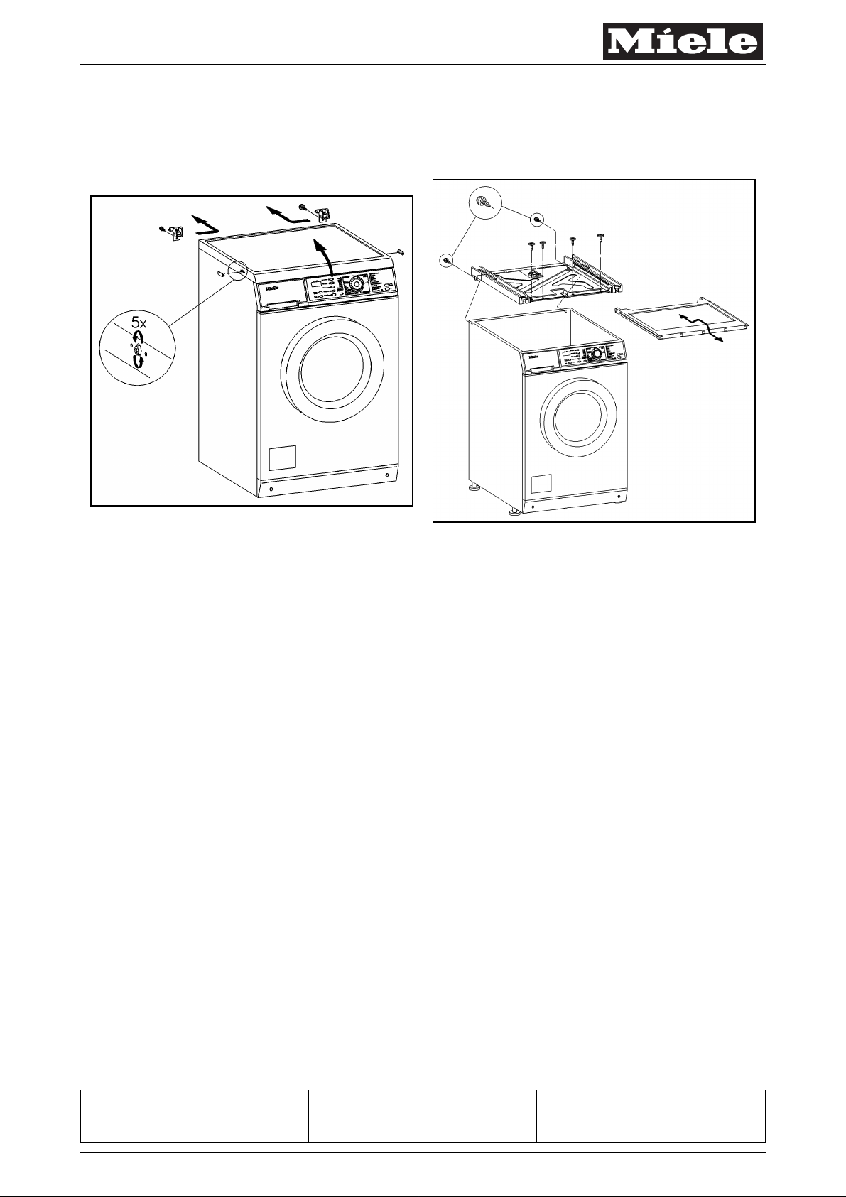
Waschautomat Deckel und Halterung Deckel abbauen, siehe Abb. 1
- Stopfen abnehmen.
- Befestigungsschrauben ca. 5 Umdrehungen losdrehen und hineindrücken.
- Deckel vorn anheben und nach hinten abnehmen.
- Halterung Deckel Befestigungsschraube herausdrehen.
- Halterung Deckel seitlich verschieben und abnehmen.
WTV auf den Waschautomat montieren, siehe Abb. 2
- Arbeitsplatte durch Drücken entriegeln, herausziehen und abnehmen.
- WTV auf den Waschautomat legen und entsprechend der Bohrungen ausrichten.
- WTV hinten mit 2 Linsenschrauben M 4 x 11 mit Zahnscheibe und vorne mit 4 Linsenschrauben M 4 x 11 am
Waschautomat-Gehäuse befestigen.
- Arbeitsplatte in WTV einführen.
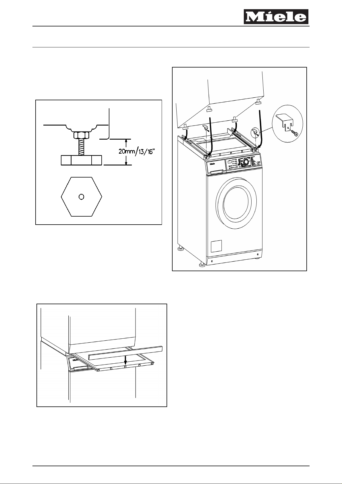
Trocknerfüße auf 20 mm einstellen, siehe Abb. 3
Hinweis
Bei Kondenstrockner: Wasserbehälter leeren.
- Trockner-Füße auf 20 mm eins tel len
- Vordere Trockner-Füße so drehen, dass vorne eine Fläche ist (die Ecken sind rechts/links).
Wasch-Trockner-Säule aufstellen, siehe Abb. 4
- Trockner auf den Waschautomaten, in die WTV-Führungsschienen stellen.
- Sicherungen in die Verbindungsschienen einsetzen und mit Linsenblechschrauben 4 x 12 befestigen.
Blende an Arbeitsplatte montieren, siehe Abb. 5
- Blende von oben in Befestigung schieben.
Gefahr!
Elektrische Sicherheit sprüfung durchführen.
D
08.07.2004 Diese Unterlagen dürfen ohne unsere Genehmigung weder vervielfältigt noch Dritten zugänglich gemacht werden, Eigentumsrechte vorbehalten.
Page 4

Produktgruppe: 19 Umbau- und Montageanweisung
4 von 6 M.-Nr. 05353262
Reason
The washer-dryer stack k its WTV 421 and WT V 423 are for washin g machine s W 1203, W 1213 or W 1215 in com bination
with dryers T 1403 or T 1405.
Parts required
Quantity Mat. no. Designation
1 06046660 Washer-dryer stack kit WTV 421 GHWS
1 06051960 Washer-dryer stack kit WTV 423 EDST
Fitting instru ction s
Danger!
Before any service work is perfor me d, the machin e mu st be positi vely di scon nectin g the pow er supp ly by remov ing the
plug from the wall receptacle.
Even with the machine switched off, power voltage may be applied to some components.
Note
Service and repair wo rk should only be carried out by an authorized qualified techn ician in accorda nce with all ap plicable
local and national safety regulations.
Servicing, modific atio n, te sti ng and m ain ten anc e of electrical appliances shoul d onl y be carried out in accordance with
all applicable safety requirements, accident prevention regulations and valid standards.
Washing machine lid and lid holder removal, Fig. 1
- Remove the screw caps.
- Loosen the lid screws with approx. 5 turns and press them in to release the retaining clips.
- Lift the lid at the front, slide it to the rear and remove it.
- Remove the screws from the two rear lid holders.
- Slide the holders to the side and remove them.
Fitting washer-dryer stacking kit on washing machine, Fig. 2
- Push the shelf slightly in to release it. Pull out the shelf to its end stop. Lift the shelf slightly and pull it forwards. Tilt the
shelf downwards and remove it.
- Lay the stacking kit in position on the washing machine and align it with the appropriate holes.
- Secure the stacking kit on the washing machine casing at the rear with 2 raised head screws M 4 x 11 and toothed
washers and at the front with 4 raised head screws M 4 x 11.
- Refit the shelf.
Dryer feet adjustment, Fig. 3
Note
Empty the condensed water container before continuing the installation.
- Adjust the dryer feet so that they protrude by 13/16 inch (= 20 mm).
- Turn the front dryer feet such that a edge faces the front (the corners are then at the right and left).
Washer-dryer stack assembly, Fig. 4
- Fit the dryer on the washing machine in its guides and slide the feet into their retaining slots.
- Insert the retaining pieces and secure them with raised head screws M 4 x 12.
Fitting fascia edge on shelf, Fig. 5
- Slide the fascia from above into it s ret a iners.
Danger!
Carry out appropriate electrical safety checks.
USA
08.07.2004 Diese Unterlagen dürfen ohne unsere Genehmigung weder vervielfältigt noch Dritten zugänglich gemacht werden, Eigentumsrechte vorbehalten.
Page 5

Produktgruppe: 19 Umbau- und Montageanweisung
5 von 6 M.-Nr. 05353262
Raison
Le cadre de superposition WTV 421/WTV 423 est prévu pour l'installation en colonne d'un lave-linge W 1203, W 1213 ou
W 1215 et d'un sèche-linge T 1403 ou T 1405.
Pièces nécessaires
Nombre Mat.-Nr. Désignation
1 06046660 Cadre de superposition WTV 421 GHWS (carrosserie blanche)
1 06051960 Cadre de superposition WTV 423 EDST (inox)
Montage
Danger !
Avant toute maintenance ou réparation sur l'appareil, déconnecter impérativement tous les câbles sous tension.
Certains éléments peuvent être sous tension réseau même si l'appareil est arrêté.
Remarque
Seul un électro-technicien qualifié est habilit é à eff ectuer le s inte rventi ons s ur l'app areil e n r espec tant le s co nsign es de
sécurité en vigueur.
Pour toute interventio n sur un appareil électrique ( réparation, modification, contrôle ou maintenance), respecter
impérativement la réglementation corresp ondante, les disposition s relatives à la prévention des accident s et les n ormes
en vigueur.
Démonter le couvercle du lave-linge et le support du couvercle, voir croquis 1
- Retirer les obturateurs.
- Desserrer les vis de fixation de 5 tours environ et les enfoncer.
- Soulever le couvercle à l'avant et le retirer par l'arrière.
- Enlever la vis de fixation du support du couvercle.
- Pousser le support du couvercle sur le côté et le retirer.
Monter le cadre de superposition WTV sur le lave-linge, voir croquis 2
-Déverrouiller la tablette par une pression et la retirer.
- Poser le cadre de superposition WTV sur le lave-linge et l'aligner par rapport aux orifices de perforation.
- Fixer le cadre de superposition WTV sur la carrosserie du lave-linge, à l'arrière avec 2 vis à tête cylindrique bombée
M 4 x 11 avec rondelle éventail et à l'avant avec 4 vis à tête cylindrique bombée M 4 x 11.
-Insérer la tablette dans le cadre de superposition WTV.
Régler les pieds du sèche-linge sur 20 mm, voir croquis 3
Remarque
En cas de sèche-linge à condensation : vider préalablement le réservoir d'eau.
-Régler les pieds du sèche-linge sur 20 mm.
- Tourner les pieds avant du sèche-linge de façon à obtenir un côté droit à l'avant (les angles sont à droite/gauche).
Installer la colonne lave-linge/sèche-linge, voir croquis 4
- Poser le sèche-linge sur le lave-linge, dans les rails du cadre de superposition WTV.
- Monter les plaquettes d'arrêt dans les rails de liaison et les fixer avec des vis 4 x 12.
Monter le bandeau sur la tablette, voir croquis 5
- Glisser le bandeau sur la fixation par le haut.
Danger !
Effectuer un contrôle de sécurité électrique.
CDN
08.07.2004 Diese Unterlagen dürfen ohne unsere Genehmigung weder vervielfältigt noch Dritten zugänglich gemacht werden, Eigentumsrechte vorbehalten.
Page 6

Produktgruppe: 19 Umbau- und Montageanweisung
6 von 6 M.-Nr. 05353262
08.07.2004 Diese Unterlagen dürfen ohne unsere Genehmigung weder vervielfältigt noch Dritten zugänglich gemacht werden, Eigentumsrechte vorbehalten.
 Loading...