

Miele S171i, S172i Service Manual
Service Manual
Vacuum Cleaner
MODELS S171i / S172i

Technical Information
S171 i / S172 i
Table of Contents
Page
1. Construction and Design 2
1.1 Features 2
1.2 Technical Data 2
1.3 Accessories 3
2. Service and Maintenance
2.1 Belt Replacement 4
2.2 Brush Roller Replacement 4
2.3 Bulb Replacement 4
2.4 Replacement of Beater Bar Selector 5
2.5 Motor Replacement 6
2.6 Carbon Brush Replacement 6
2.7 Thermal Fuse Replacement 6
2.8 Power Cord Replacement 7
2.9 On-Off Switch Replacement 7
2.10 Power Control Replacement 8
2.11 Potentiometer Replacement 8
2.12 Troubleshooting Guide 9
9.0 Wiring Diagrams
9.1 S171i 10
9.2 S172i 11
10. Parts List 12 - 17
1

1.0 Construction & Design
1.1 Features
Features S171I S172I
Technical Information
S171 i / S172 i
Variable Motor Speed
Automatic Cord Rewind
Change Bag Indicator
Bare Floor Adjustment
Double Beater Bar
Double Beater Brush
Headlight
Brush Edge Cleaning
Micron Filtration
Integrated Tool Storage
•••••
•••••
•••••
•••••
•••••
•••••
••••
••••
•
••
••••
•
••
•
••
••••
•
••
•
••
•
••
1.2 Technical Data
1.2.1 Water Lift 49.2 inches
1.2.2 Air Flow 50 CFM
1.2.3 Dust Bags 2 ply recyclable paper
1.2.4 Dust Bag Volume 6 quarts
1.2.5 Operational Radius 25 feet standard
34 feet with Extension
1.2.6. Weight S171i - 13.7 lbs
S172I - 14.1 lbs
1.2.7 Electrical Connection 120 Vac, 60 Hz
1.2.8 Rated Load 800 Watts
1.2.9 Motor Power 7.3 Amp
1.2.10 Safety Classification Double Insulated
1.2.11 Safety Certification ETL 9700717
1.2.12 Cord Length 24.9 feet
1.2.13 Change Bag Indicator Both S171I & S172I
1.2.14 Brush Roll Both S171I & S172I
1.2.15 Filtration Pre Motor Filtration, Electrostatic Super
Clean Filter
2

Technical Information
S171 i / S172 i
1.3 Accessories
1.4 Standard Accessories Extension Wand
Crevice Tool
Dusting Brush
3

2.0 REPLACING THE MAIN PARTS
Technical Information
S171 i / S172 i
IMPORTANT:
ALWAYS UNPLUG THE VACUUM FROM THE
ELECTRICAL SUPPLY.
BEFORE REPLACING ANY PART
2.1 REPLACING THE BELT
1. Loosen the 4 screws from the base plate and
remove base plate. (Fig. 1)
2. Release the belt from the m ot or shaft and then
lift up the rotary brush assembly to remove the
belt. (Fig. 2)
3. Install the new belt around the pulley and motor
shaft.
4. Re-install the base plate and tighten the scr ews.
2.2 REPLACING THE ROTARY BRUSH
ASSEMBLY
1. Remove the base plate and rotary brush
assembly as outlined in Section 2.1.
2. Install the new assembly by first installing t he
belt around the pulley and placing the brush
ends into their holders. Next, pull the belt over
the motor shaft. (Fig. 3)
3. Re-install the base plate and tighten the scr ews.
2.3 REPLACING THE BULB
1. Remove the base plate as outlined in Section
2.1.
2. Release the fastening flange and lift the
complete head-light assembly out of t he
vacuum. (Fig. 4)
3. Pull out the bulb and replace it with a new one.
(Fig. 5)
4. Press the headlight assembly back into place.
5. Re-install the base plate and tighten the scr ews.
4
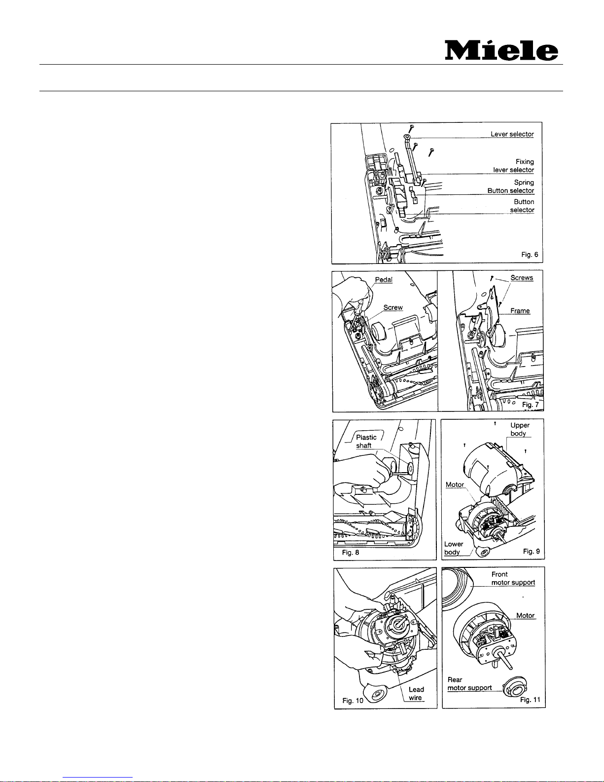
2.4 REPLACING THE BEATER BAR
SELECTOR
1. Remove the base plate as outlined in section
2.1.
2. Release the belt from the m ot or shaft.
3. Loosen the screw holding the lever selector,
two holding the fixing lever selector and one
holding the spring button selector. (Fig. 6)
4. Replace any damaged parts and re-assemble
in the reverse order.
2.5 REPLACING THE MOTOR
1. Remove the base plate as outlined in section
2.1.
2. Release the belt from the m ot or shaft.
3. Remove the screw holding the pedal and
the two holding the frame. ( Fig. 7)
4. Insert a flat-head screwdriver at the nozzle
housing and carefully pry out the plastic shaft .
Remove the floor nozzle cover.(Fig. 8)
5. Turn the vacuum cleaner over and remove the
four screws from the upper body. (Fig. 9)
6. Take out the motor and r em ove the t wo lead
wires (provided with quick-terminals) from
the carbon brush holder terminals. (Fig. 10)
7. Dismount the front / r ear motor supports and
replace the motor. (Fig. 11)
8. Assemble the front / r ear m ot or supports on to
the new motor and connect the two lead
wires to the carbon brush holder terminals.
9. Place the motor in the lower body and re install the rest of the part s in r everse
order.
Technical Information
S171 i / S172 i
2.6 REPLACING THE CARBON BRUSHES
5
 Loading...