

Page 1
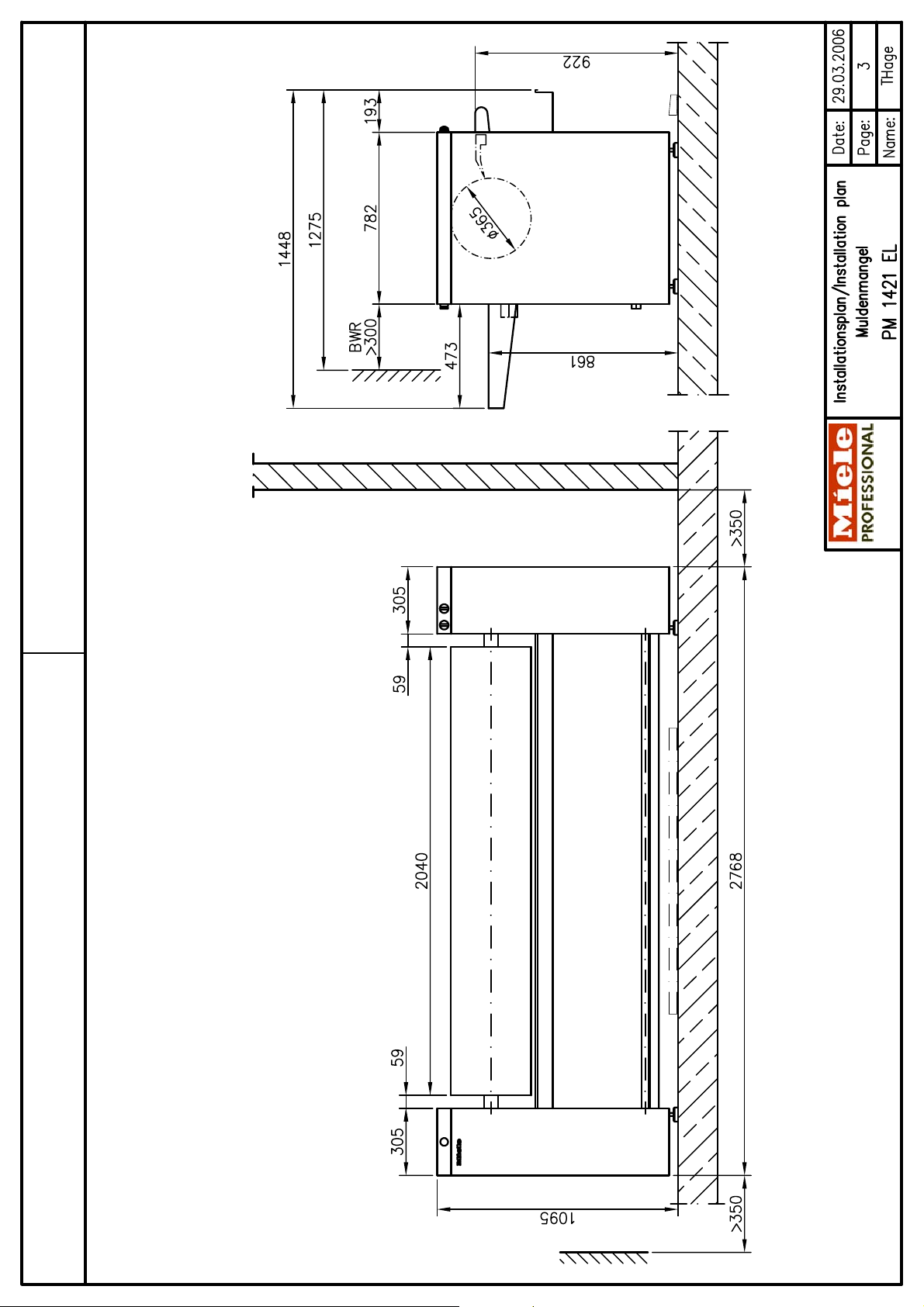
Installationsplan / Installation plan
Installatietekening
Plan d`installation
Piano di installazione
Plano de instalación
Plano de instalação
Σχέδιο εγκατάστασης
Asennusohje
Installasjonsplan
Installationsplan
G
PM 1421 EL
Materialnummer / Mat. no.: 06 797 580
Änderungsstand / Version: 02
Datum Zeichnung / Drawing date: 29.03.2006
Datum Legende / Legend date: 29.03.2006
Page 2

Page 3
Page 4

Page 5

Page 6

Technical Datasheet
Flatwork ironers:
Heating:
PM 1421
Electric (EL)
Legend:
Circled, bold-type abbreviations:
Connection required
Abbreviations surrounded by broken circle:
Connection optional or required, depending on model
G
Optional extras:
BWR
Return feed kit Optional equipment to return ironed laundry to the front of the
machine for single-person operation.
Machine connections:
Electrical
connection
Fuse rating A 3 × 50
Supply lead (H 07 RN-F), min. cross-section mm² 5 × 10
with threaded cable connector M 40 x 1.5
1. Standard voltage (as supplied) V 3N AC 380-415
Frequency Hz 50 (60)
Rated load kW 23.7
Switched plug and socket connection in accordance with IEC
On-site vent connection (interior diameter) mm 75
Max. temperature °C 90
As relative humidity can be as high as 100%, suitable
If the machine fan is unable to transport air over the on-site
Machine connection (d
60309 and IEC 60947 recommended to facilitate electrical
safety tests.
Install mains isolator according to IEC 60947 on hard-wired
connection.
Wall socket or mains isolator must be accessible after
installation.
The use of an earth leakage circuit breaker (ELCB) is strongly
recommended.
If necessary, equipotential bonding with good galvanic contact
must be provided in accordance with all appropriate national
and local regulations.
For installation of supply lead in plasterwork Conduit
Nominal air throughput in vented mode m³/h 160 Vented
Permissible pressure attenuation Pa 100
measures must be taken to prevent a backflow of condensate
into the machine.
vent ducting distance, an additional fan with a suitable
capacity must be installed either in the ducting or at the point
of discharge to atmosphere.
× s × l) [DN 70] mm 75 × 2.0 × 58
ext
Sufficient air intake should be available to replace displaced
volume of air.
Installationsplan PM 1421 EL
Stand: 29.03.2006 Seite 6
Page 7

Floor bolts Fittings (supplied)
4 × rawl plugs (Ø × length) mm 10 × 50
Machine must be bolted to the floor!
Fixing materials for floating screed floor to be provided on site
Machine data Width mm 2768
Depth mm 1448
Height mm 1095
Min. access width to installation site mm 953
Minimum side wall gap mm 350
Minimum rear wall gap (when using BWR kit) mm 300
Net weight kg 441
Dynamic floor load, max. N 4571
Average heat dissipation
Acoustic power level (re1 pW) dB (A) not yet available
Sound pressure level dB (A) < 70
(measured at a distance of 1 m from the machine and at a
Installation should only be carried out by authorised fitters in accordance with valid regulations!
Observe installation instructions when installing machine! All rights reserved! Measurements in mm
4 × screws DIN 571 (Ø × length) mm 8 × 50
4 × safety claws
W 3800
(dependent on ambient room temperature and throughput)
height of 1.6 m)
Installationsplan PM 1421 EL
Stand: 29.03.2006 Seite 7
 Loading...