

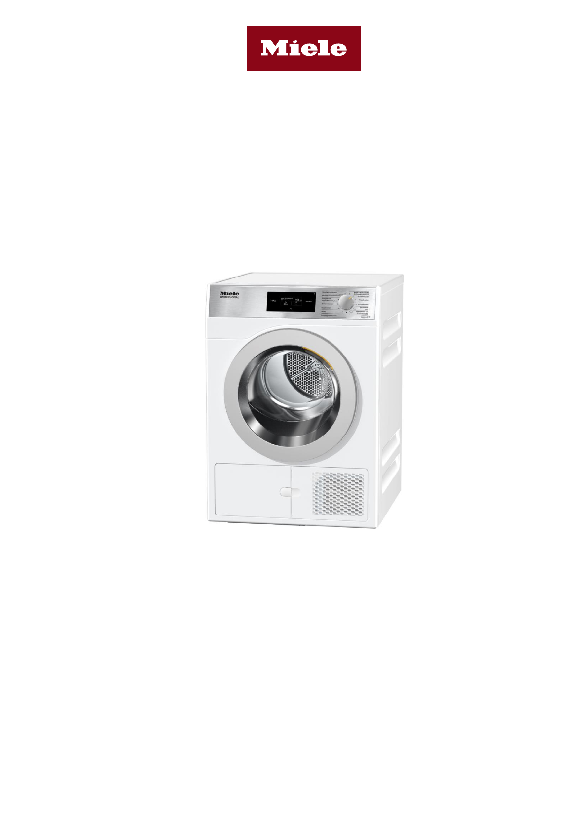
Installation plan
Vented dryer
PDR 507 EL
It is essential to read the operating and installation instructions before installation
and commissioning.
This prevents both personal injury and damage to the appliance.
en-GB
11 277 080/04

2 11 277 080/04
United Kingdom
Miele Co. Ltd.
Fairacres, Marcham Road
Abingdon, Oxon, OX14 1TW
Professional Sales, Tel.: 0845 365 6608
E-mail: professional@miele.co.uk
Website: www.miele.co.uk/professional
South Africa
Miele (Pty) Ltd
63 Peter Place, Bryanston 2194
P.O. Box 69434, Bryanston 2021
Tel.: (011) 875 9000, Fax: (011) 875 9035
E-mail: info@miele.co.za
Website: www.miele.co.za
Australia
Miele Australia Pty. Ltd.
ACN 005 635 398
ABN 96 005 635 398
1 Gilbert Park Drive, Knoxfield, VIC 3180
Tel.: 1300 731 411
Website: www.miele-professional.com.au
E-mail: info@miele-professional.com.au
New Zealand Miele
New Zealand Limited
IRD 98 463 631
Level 2, 10 College Hill
Freemans Bay, Auckland 1011, NZ
Tel.: 0800 464 353
Website: www.miele-professional.com.au
E-mail: info@miele-professional.com.au
United Arab Emirates
Miele Appliances Ltd.
Showroom 1, Eiffel 1 Building
Sheikh Zayed Road, Umm Al Sheif
P.O. Box 114782 - Dubai
Tel. +971 4 3044 999, Fax. +971 4 3418 852
800-MIELE (64353)
E-mail: info@miele.ae
Website: www.miele.ae
Singapore
Miele Pte. Ltd.
163 Penang Road
# 04–03 Winsland House II
Singapore 238463
Tel.: +65 6735 1191, Fax: +65 6735 1161
E-mail: info@miele.com.sg
Website: www.miele.sg
Malaysia
Miele Sdn Bhd
Suite 12–2, Level 12
Menara Sapura Kencana Petroleum
Solaris Dutamas No. 1, Jalan Dutamas 1
50480 Kuala Lumpur, Malaysia
Tel.: +603-6209-0288
Fax: +603-6205-3768
India
Miele India Pvt. Ltd.
Ground Floor, Copia Corporate Suites
Plot No. 9, Jasola
New Delhi – 110025
Tel.: 011-46 900 000, Fax: 011-46 900 001
E-mail: customercare@miele.in
Website: www.miele.in
Ireland
Miele Ireland Ltd.
2024 Bianconi Avenue
Citywest Business Campus, Dublin 24
Tel.: (01) 461 07 10, Fax: (01) 461 07 97
E-mail: info@miele.ie
Website: www.miele.ie
Miele (Hong Kong) Limited
41/F–4101, Manhattan Place
23 Wang Tai Road
Kowloon Bay, Hong Kong
Tel.: (852) 2610 1025, Fax: (852) 3579 1404
E-mail: customerservices@miele.com.hk
Website: www.miele.hk
China
Miele (Shanghai) Trading Ltd.
1–3 Floor, No. 82 Shi Men Yi Road
Jing’ an District, 200040 Shanghai, PRC
Tel.: +86 21 6157 3500, Fax: +86 21 6157 3511
E-mail: info@miele.cn
Website: www.miele.cn
Manufacturer:
Miele & Cie. KG
Carl-Miele-Straße 29
33332 Gütersloh, Germany
Key:
Connection required
Connection optional or required,
depending on model
AL
Exhaust air
KLZ
Cooling air intake
ASK
Condensate drain hose
PA
Equipotential bonding
B
Appliance anchoring
SLA
Peak-load connection
EL
Electrical connection
UG
Box plinth
F
Appliance feet, adjustable
UO
Open plinth
KG
Payment system
APCL
Washer-dryer stacking kit
KGA
Payment system connection
XKM
Communication module
KLA
Cooling air vent
ZL
Air intake
All rights reserved.12/19
PDR 507 EL en-GB
11 277 080/04 3
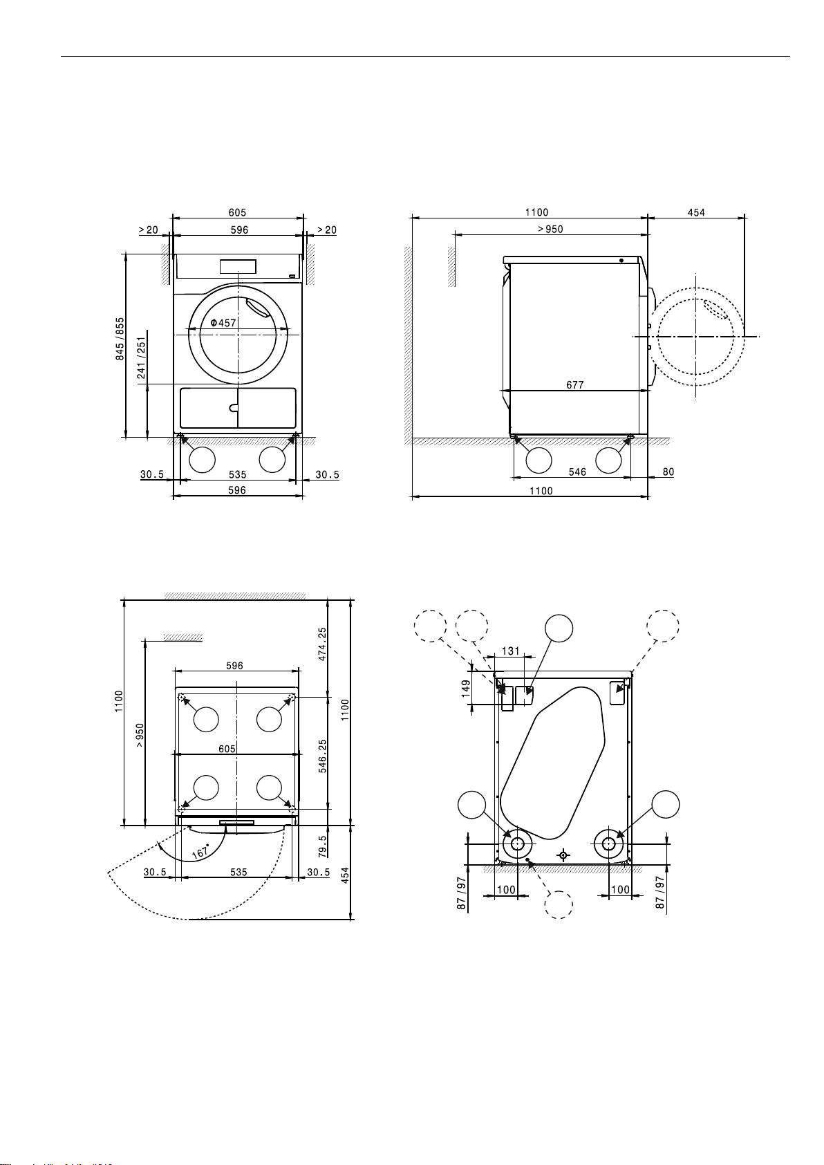
Appliance dimensions
F
F
F F
F F
F F
PA
AL
EL
KGASLA
AL
XKM
PDR 507 EL en-GB
4 11 277 080/04
Installation
KGEL
ALAL
EL KG
AL
KGA
SLA
PA
KGEL
AL
AL
UO UG /
UO UG /
EL KG
AL
KGA
SLA
PA

PDR 507 EL en-GB
11 277 080/04 5
Washer-dryer stack
F F
FF

PDR 507 EL en-GB
6 11 277 080/04
Installation

PDR 507 EL en-GB
= standard, = optional, + = only on request, - not available
11 277 080/04 7
Technical data
PDR 507 EL
Drying system
Vented
Drum volume
l
130 Load capacity
kg
7.0 Door opening diameter
mm
370
Electrical connection (EL)
Standard voltage
3N AC 400 V
Frequency
Hz
50/60 Total rated load
kW
6.4 Fuse rating (B trip rating according to EN 60898)
A
3 x 10
Supply lead min. cross-section
mm²
5 x 1.5
Supply lead without plug
Length of supply lead
mm
2000
Alternative voltage (convertible by Miele Customer Service Department)
1N AC 230 V
Frequency
Hz
50/60 Total rated load
kW
3.24 Fuse rating (B trip rating according to EN 60898)
A
1 x 16
Supply lead min. cross-section
mm²
3 x 1.5
Alternative voltage (convertible by Miele Customer Service Department)
3 AC 230 V
Frequency
Hz
50/60 Total rated load
kW
6.4 Fuse rating (B trip rating according to EN 60898)
A
3 x 16
Supply lead min. cross-section
mm²
4 x 1.5
Non-standard voltages MAR 400/440/480 (Marine)
3 AC 400/440/480 V
Frequency
Hz
50/60 Total rated load
kW
4.5/5.4/6.4
Fuse rating (B trip rating according to EN 60898)
A
3 x 10
Supply lead min. cross-section
mm²
4 x 1.5
Supply lead without plug
Length of supply lead
mm
2000
Variations in the following countries:
Standard voltage 13 A (GB only)
3N AC 400 V
Frequency
Hz
50/60 Total rated load
kW
5.47 Fuse rating (B trip rating according to EN 60898)
A
3 x 13
Supply lead min. cross-section
mm²
5 x 1.5
Supply lead without plug
Length of supply lead
mm
2000
Standard voltage 13 A (GB only)
1N AC 220–230 V
Frequency
Hz
50/60 Total rated load
kW
2.76–2.99
Fuse rating (B trip rating according to EN 60898)
A
1 x 13
Supply lead min. cross-section
mm²
3 x 1.5
Supply lead with plug
Length of supply lead
mm
2000
Standard voltage 25 A (GB only)
1N AC 220–230 V
Frequency
Hz
50/60 Total rated load
kW
5.03–5.47
Fuse rating (B trip rating according to EN 60898)
A
1 x 25
Supply lead min. cross-section
mm²
3 x 2.5
Supply lead without plug
Length of supply lead
mm
2000

PDR 507 EL en-GB
= standard, = optional, + = only on request, - not available
8 11 277 080/04
Technical data
PDR 507 EL
Standard voltage (N only)
3 AC 230 V
Frequency
Hz
50/60 Total rated load
kW
6.4 Fuse rating (B trip rating according to EN 60898)
A
3 x 16
Supply lead min. cross-section
mm²
4 x 1.5
Supply lead without plug
Length of supply lead
mm
2000
Alternative voltage (convertible)
1N AC 230 V
Total rated load
kW
3.24 Fuse rating (B trip rating according to EN 60898)
A
1 x 16
Supply lead min. cross-section
mm²
3 x 1.5
Alternative voltage (convertible)
3N AC 400 V
Frequency
Hz
50/60
Total rated load
kW
6.4 Fuse rating (B trip rating according to EN 60898)
A
3 x 10
Supply lead min. cross-section
mm²
5 x 1.5
Vented (EL)
Connection (ext. diameter)
mm
100 Max. exhaust air temperature
°C
80
Electrical connection with 50 Hz/60 Hz
Max. permissible pressure loss
Pa
340 Max. flow rate w/o counterpressure (0 Pa) in vented mode
m³/h
285
Equipotential bonding (PA)
Appliance connection (with installation kit)
XCI box LG interface
Peak load/energy management (SLA)
Appliance connection (with XCI box LG)
Payment system connection (KGA)
Connection of payment systems (with XCI box LG)
Communication module (XKM)
Communication module XKM 3200 WL PLT
Installation on appliance feet (F)
No. of appliance feet
No. 4
Appliance foot, height-adjustable with thread
mm
± 5 Appliance foot diameter
mm
31.7
Anchoring (B)
Standard anchoring
Floor anchor kit (for 4 machine feet)
Wood screws according to DIN 571
mm
6 x 50
Rawl plugs (diameter x length)
mm
8 x 40
Anchoring of Miele plinths
Miele plinth installation (fasteners included)
Required anchor points
No. 4
Wood screws according to DIN 571
mm
8 x 65
Rawl plugs (diameter x length)
mm
12 x 60

PDR 507 EL en-GB
= standard, = optional, + = only on request, - not available
11 277 080/04 9
Technical data
PDR 507 EL
Plinth floor anchoring (to be provided on site)
Appliance installation on on-site plinth (concrete or masonry)
Min. plinth installation footprint (W/D)
mm
600/650
Wood screws according to DIN 571
mm
6 x 50
Rawl plugs (diameter x length)
mm
8 x 40
Appliance data
Overall appliance dimensions (H/W/D)
mm
850/605/717
Casing dimensions (H/W/D)
mm
850/596/677
Site-access dimensions (H/W)
Min. site-access opening (excl. packaging)
mm
900/605
Installation dimensions
Min. side gap
mm
20
Recommended side gap – washer-dryer stack
mm
300 Min. distance to opposite wall from appliance front
mm
950 Recommended distance to opposite wall from appliance front
mm
1100
Weights and floor loads
Appliance weight (net weight)
kg
50
Max. floor load in operation
N
670
Emissions
Sound pressure level (in accordance with EN ISO 11204/11203)
dB(A)
<70
Heat dissipation rate to installation site
W
200

PDR 507 EL en-GB
10 11 277 080/04
Installation and planning notes
Installation requirements
The tumble dryer should only be connected to a power supply
provided in accordance with all appropriate local and national
legislation and regulations.
In addition, all regulations issued by the appropriate utilities as well as
standards relating to occupational safety and all applicable valid
regulations and technical standards must be observed.
General operating conditions
Ambient temperature in installation room: +2 °C to +35 °C.
Electrical connection
Depending on the model, the tumble dryer is delivered with a supply
lead with/without a plug.
The appliance may only be connected to an electrical system that
conforms to the national and local codes and regulations (BS 7671 in
the UK). The installation must be performed by a qualified electrician.
The data plate indicates the nominal power consumption and the
appropriate fuse rating. Compare the specifications on the data plate
with those of the electrical power supply.
It is always recommended to connect the appliance via a plug and
socket so that electrical safety checks, e.g. during repair or service
work, can be carried out easily.
The appliance can either be hard-wired or connected using a plugand-socket connection in accordance with IEC 60309-1. If the
appliance is hard-wired, a dual circuit breaker must be provided on
site. When switched off there must be an all-pole contact gap of at
least 3 mm in the isolator switch (including circuit breakers, fuses and
contactors according to IEC/EN 60947).
The plug connector or isolator switch should be easily accessible at all
times. If the appliance is disconnected from the electricity supply, the
isolator must be lockable or the point of disconnection must be
monitored at all times.
The tumble dryer should never be connected by an extension
cable, e.g. power strips, to avoid the risk of fire.
New connections, modifications to the system or servicing of the
earthing conductor, including determining the correct fuse amperage,
must be carried out by a qualified electrician, as they are familiar with
the pertinent regulations and the specific requirements of the electric
utility company.
If converting the tumble dryer to an alternative voltage, observe the
instructions in the wiring diagram. Conversion must be performed
by the Miele Customer Service Department or by an authorised
Miele dealer. The heater rating must also be adapted.
The appliance must not be connected to devices such as timers which
would switch it off automatically.
References to cable cross-sections in the technical data refer only to
the required mains cable. Please consult relevant local and national
regulations when calculating any other wire gauges.
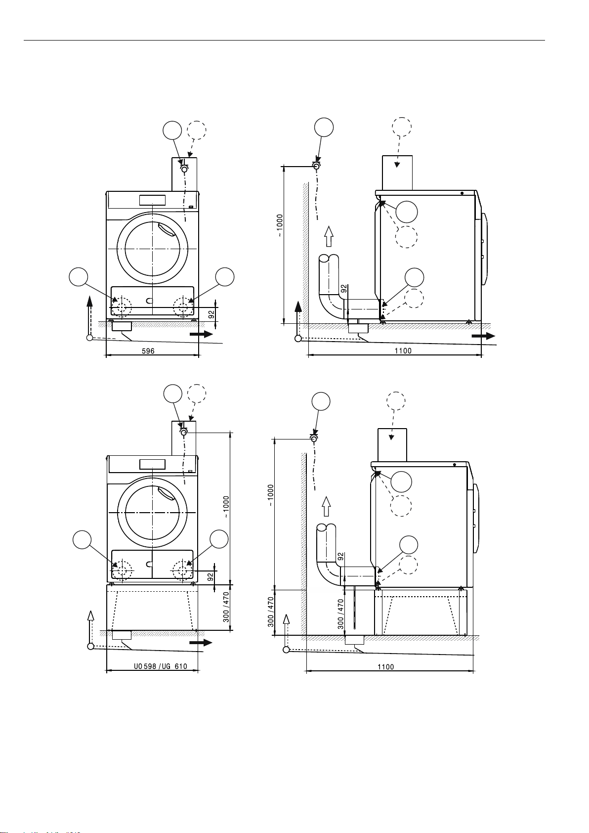
Vent connection
Hot moist exhaust air should be vented to atmosphere along the
shortest possible route or connected to a suitable vent system.
Depending on the duct path, the moist exhaust air can condense on
the duct walls to a greater or lesser extent. For this reason it is
recommended to lay ducting with a downwards slope to the air exit.
If ducting slopes upwards, a condensate trap either with a drip tray or
a connection to a suitable on-site floor drain must be fitted in the
system at the lowest point.
Condensate must not flow back into the appliance.
It is permissible to vent exhaust air via an external wall. In this case,
measures must be taken to minimise the risk and annoyance to
neighbouring buildings.
The end of exhaust air ducting leading into the open should be
protected against the elements, e.g. using a suitable hood or with a
90° bend.
The cross-sectional area of the ducting must not be reduced or
obstructed by built-in parts. Filters and louvres must not be fitted in the
ducting.
Congestion in the line may lead to a drop in appliance performance or
to appliances being switched off to guarantee safety.
Proper functioning of the tumble dryer cannot be guaranteed if the
max. permissible pressure loss is exceeded in the on-site vent
ducting system.
When connecting several tumble dryers to a common duct, the crosssectional area of the duct must be increased accordingly.
Additionally, in such a case every tumble dryer must have its own
non-return valve to prevent dryers affecting others in the system. This
requires the provision of on-site additional parts.
In the event that exhaust air ducts from several tumble dryers are
merged into a common duct, a non-return device should be
installed in each separate line to prevent backflow.
With complex ducting with many bends and additional components, or
with the connection of several different tumble dryers to a common
duct, it is recommended that a detailed calculation is carried out by a
suitable specialist.
Air intake
The air supply for the tumble dryer is taken directly from the
installation site.
During operation, adequate ventilation of the installation site should be
guaranteed. Depending on the appliance version, it is necessary to
ensure an intake of fresh air to compensate for the volume of exhaust
air extracted in order to avoid the creation of a vacuum.
It should not be possible to close or otherwise obstruct air intake
grilles or alternative measures should be implemented to ensure that
an adequate supply of fresh air is available at all times during
appliance operation.
Equipotential bonding
If necessary, equipotential bonding with good galvanic contact must
be guaranteed in compliance with all applicable local and national
installation specifications.
Connection material for equipotential bonding must be provided on
site or using a kit available from the Miele Customer Service
Department.
Peak load/energy management
The appliance can be connected to a peak-load or energy
management system using an optional kit.
When the peak-load function is activated, the heating is deactivated.
A message appears in the display to inform you of this.

PDR 507 EL en-GB
11 277 080/04 11
Payment system
The tumble dryer can be fitted with a single-machine payment system
as an optional accessory using an optional kit (XCI box).
The programming required for connecting a payment system can be
carried out during the initial commissioning process. After initial
commissioning, changes may only be carried out by your Miele dealer
or the Miele Customer Service Department.
Interface
The appliance can be fitted with an XKM 3200 WL PLT
communication module.
This module can be used as a WiFi or LAN interface.
The LAN interface provided via the module complies with SELV
(Safety Extra Low Voltage) in accordance with EN 60950. Connected
appliances must also comply with SELV. The LAN connection uses a
RJ45 connector in accordance with EIA/TIA 568-B.
Installation and anchoring
The appliance must be installed on a perfectly smooth, level and firm
surface which is able to withstand the quoted loads.
The floor load created by the appliance is concentrated and
transferred to the installation footprint via the appliance feet.
The appliance should be levelled in both directions with the aid of the
adjustable feet.
Plinth installation
The tumble dryer can be installed on a plinth (open or box plinth,
available as an optional Miele accessory) or on a concrete plinth to be
provided on site.
The quality of the concrete and its strength must be assessed
according to the appliance load. Ensure that any raised concrete
plinth is adequately bonded to the floor below.
Washer-dryer stack
The tumble dryer can be installed as a washer-dryer stack together
with a Miele washing machine. A stacking kit (optional accessory) is
required for this.
Installation of the stacking kit must be performed by the Miele
Customer Service Department or an authorised Miele service
technician.
 Loading...