

Page 1
Installation Instructions
Gas Cooktop
KM 404
KM 406
To prevent accidents and
machine damage,
read these instructions
before installation or use.
®
UV
M.-Nr. 05 060 881
®
Page 2
WARNING:
If the information in this manual is not followed
exactly, a fire or explosion may result causing
property damage, personal injury or death.
Do not store or use gasoline or other flammable
–
vapors and liquids in the vicinity of this or any
other appliance.
WHAT TO DO IF YOU SMELL GAS
–
ß Do not try to light any appliance.
ß Do not touch any electrical switch.
ß Do not use any phone in your building.
ß Immediately call your gas supplier from a
neighbor’s phone. Follow the gas supplier’s
instructions.
ß If you cannot reach your gas supplier, call the
fire department.
– Installation and service must be performed by a
qualified installer, service agency or the gas
supplier.
(In Massachusetts a licensed plumber / gas fitter)
–
Note to the installer:
Please leave this instruction book with the
consumer for the local electrical / gas inspector’s
use.
2
Page 3

Contents
IMPORTANT SAFETY INSTRUCTIONS. . . . . . . . . . . . . . . . . . . . . . . . . . . . . . . . . 4
Cooktop dimensions . . . . . . . . . . . . . . . . . . . . . . . . . . . . . . . . . . . . . . . . . . . . . . . 6
KM 404. . . . . . . . . . . . . . . . . . . . . . . . . . . . . . . . . . . . . . . . . . . . . . . . . . . . . . . . . . . 6
KM 406. . . . . . . . . . . . . . . . . . . . . . . . . . . . . . . . . . . . . . . . . . . . . . . . . . . . . . . . . . . 7
Countertop cut-out . . . . . . . . . . . . . . . . . . . . . . . . . . . . . . . . . . . . . . . . . . . . . . . . 8
Installation . . . . . . . . . . . . . . . . . . . . . . . . . . . . . . . . . . . . . . . . . . . . . . . . . . . . . . . 9
Laying out the support bars and brackets . . . . . . . . . . . . . . . . . . . . . . . . . . . . . . . 9
Setting the cooktop into place . . . . . . . . . . . . . . . . . . . . . . . . . . . . . . . . . . . . . . . . 11
Electrical connection. . . . . . . . . . . . . . . . . . . . . . . . . . . . . . . . . . . . . . . . . . . . . . 13
Gas connection . . . . . . . . . . . . . . . . . . . . . . . . . . . . . . . . . . . . . . . . . . . . . . . . . . 14
Gas pressure regulator . . . . . . . . . . . . . . . . . . . . . . . . . . . . . . . . . . . . . . . . . . . . . 15
Nominal ratings . . . . . . . . . . . . . . . . . . . . . . . . . . . . . . . . . . . . . . . . . . . . . . . . . . . 16
Converting to another type of gas . . . . . . . . . . . . . . . . . . . . . . . . . . . . . . . . . . . 17
3
Page 4
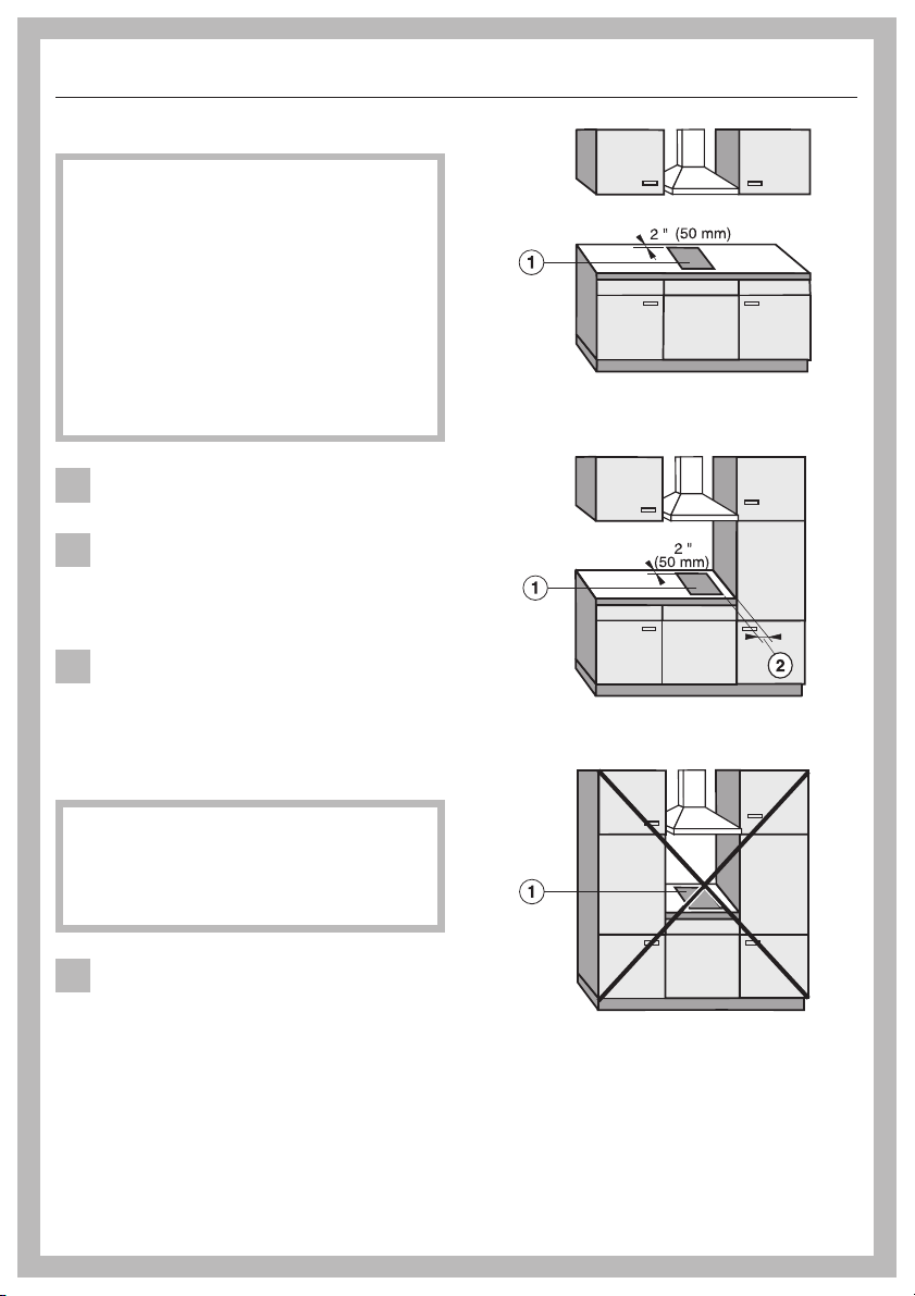
IMPORTANT SAFETY INSTRUCTIONS
Installation
The minimum distances given in
these Installation instructions are to
combustible surfaces, and must be
observed to ensure safe operation.
Failure to do so increases the risk of
fire.
The cabinetry and venting hood
should be installed first to prevent
damage to the cooktop.
Gas appliances should only be
installed in a well ventilated area.
The countertop must be bonded
with heat resistant (212 °F/100 °C)
adhesive to prevent distortion or
dissolving.
The cooktop should only be
installed as shown in the
illustrations while maintaining the
required safety distances shown. Do
not install the cooktop between two tall
cabinets, this is a fire hazard.
recommended
not recommended
a = indicates cooktop cut-out
b = minimum distance between
cut-out and a tall cabinet:
12" (305 mm)
This appliance has not been
designed for maritime use or for
use in mobile installations such as
recreational vehicles or aircraft.
However, under certain conditions it
may be possible for installation in these
applications. Please contact the Miele
Technical Service Department with
specific requirements.
4
not allowed
Page 5
IMPORTANT SAFETY INSTRUCTIONS
The cooktop must not be installed
over a dishwasher, washer, dryer,
refrigerator or freezer. Heat radiated by
the cooktop may damage the
appliances.
Deep fat fryers must not be
installed next to gas cooktops. Gas
flames can ignite splattering oil. A
distance of at least 12" (305 mm)
should be maintained between these
two appliances. The minimum distance
between two cooktops must be 4"
(100 mm).
Install the appliance so that the
power cord or gas piping does not
come into contact with any portion of
the cooktop which may become hot
during use.
This appliance must be installed
with its own shut off valve and the
included gas pressure regulator.
Both the valve and the regulator
must be easily accessible to the
consumer after the appliance is
installed.
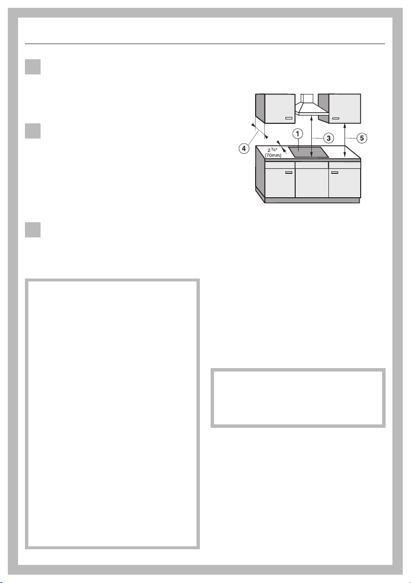
Safety distances above the
appliance
There must be a safety distance of at
least 30" (760 mm), c between the
appliance and any objects above it.
The overhead cabinet depth, d, if
unprotected, must not exceed 13"
(330 mm). The minimum distance of
combustible surfaces located above
and to the sides of the cooktop, e, is
18" (457 mm).
If the cabinet manufacturer
recommends a greater distance, follow
that manufacturers recommendation.
This appliance must be
disconnected from the gas supply
during any pressure testing of the
system performed in excess of
1
/2psi (3.5 kPa). This appliance
must be isolated at test pressures
equal to or less than
(3.5 kPa).
Any pipe connections must be made
using a thread sealant approved for
gas connections. Failure to correctly
install these items could lead to a
gas leak and subsequent explosion.
1
/2psi
When installing the cooktop under a
venting hood, always observe the
minimum distance recommended by
the hood manufacturer.
Keep this instruction book in a safe
place for reference and pass it on to
any future user.
5
Page 6
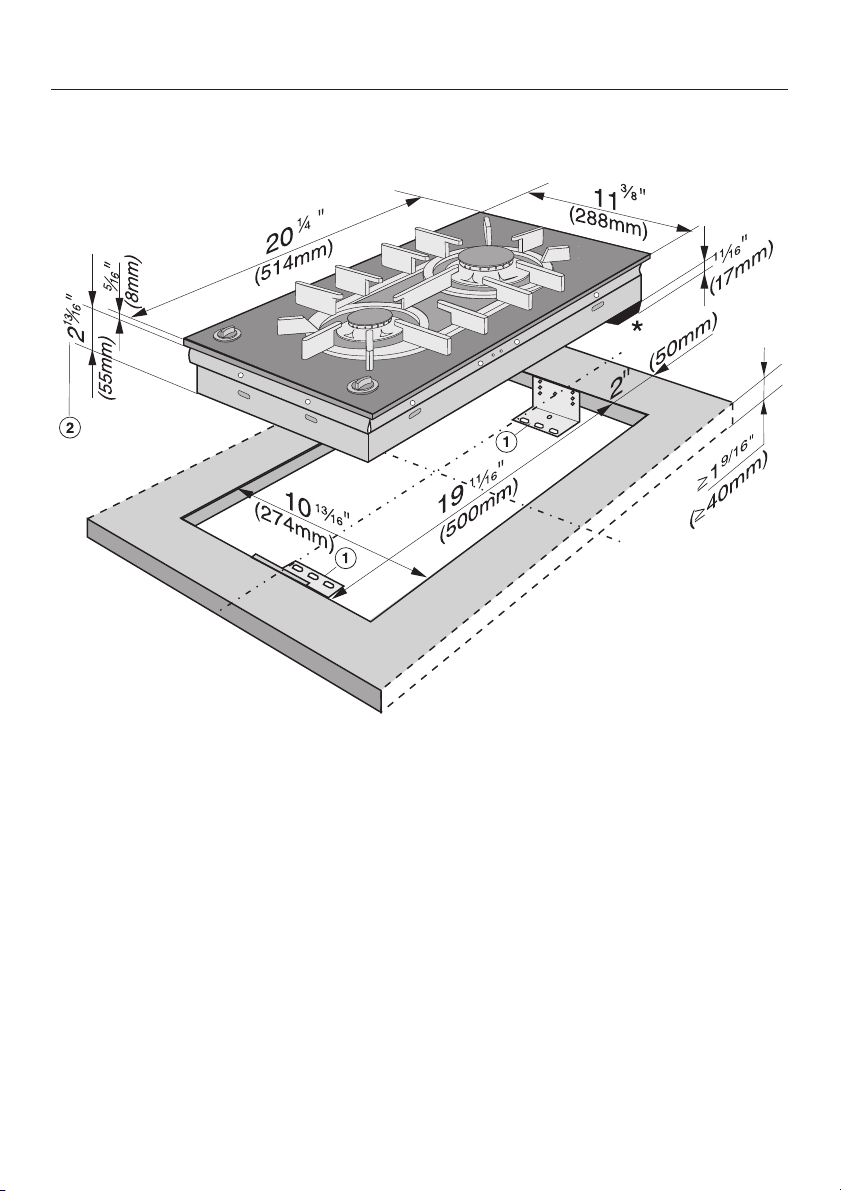
Cooktop dimensions
KM 404
a Support brackets
b Building in height plus
1
/8" (3 mm) for
the fixing screws
* Please allow an additional 3
1
/2"
(90 mm) depth across the rear of the
cooktop for clearance of the gas
regulator (see "Gas connection" for
illustration).
6
Page 7

KM 406
Cooktop dimensions
a Support bracket
b Building in height plus
1
/8" (3 mm) for
the fixing screws
* Please allow an additional 3
1
/2"
(90 mm) depth across the rear of the
cooktop for clearance of the gas
regulator (see "Gas connection" for
illustration).
7
Page 8

Countertop cut-out
Installing one or multiple appliances:
Cut out the countertop using the
dimensions listed in the following table.
All Miele combisets have the same
length and width. Make sure that there
is enough room under the countertop to
allow for the depth of the various
appliances. Remember to allow
clearance for the gas regulator and gas
pipe that must be connected to the
appliance.
^ Rember to maintain the minimum
safety distances to combustible
surfaces:
3
– 2
/4" (70 mm) between the cut-out
and the back wall, and
– 12 " (305 mm) between the cut-out
and a side wall or tall unit to the right
or left of the cut-out.
Number of
cooktops
Cut out width
Dimension "B"
1 1013/16" (275 mm)
2 221/8" (562 mm)
3 331/2" (851 mm)
4 4413/16" (1138 mm)
5 561/8" (1426 mm)
6 671/2" (1714 mm)
7 7813/16" (2002 mm)
The tolerance for each dimension is
1
/16" (1 mm).
When installing more than one
combiset, a support bar must be
installed between the appliances.
Install the support bars as shown in
the relevant section before setting
the appliances into the countertop.
^
See "IMPORTANT SAFETY
INSTRUCTIONS" for further
installation information.
8
Page 9

Laying out the support bars
and brackets
Installation
a Support brackets
b Support bars
c Slight gap between support bar and
countertop
d Bracket center line
The illustration shows the layout for
three combisets and their respective
support bars, b, and support brackets,
a, required for correct installation.
If more than three combisets are being
installed, add an additional 11
(290 mm) to the overall length of the cut
out for each additional combiset, or use
the table on the preceding page.
3
/8"
9
Page 10

Installation
Securing the support bars
d
c
Wood or Corian countertops
^ Arrange the bars, b, as shown in the
illustration.
1
^ Drill
^ Fill the gap, c, between the bars and
/16" (1.5 mm) pilot holes through
the brackets and secure them using
the supplied screws.
the countertop using the supplied
silicon sealant.
Securing the support brackets
^ Place the brackets, a, as shown in
the illustration.
^ Drill two
each bracket and secure them using
the supplied screws.
Granite countertops
1
/16" (1.5 mm) pilot holes for
Granite countertops
For granite countertops, the support
bars, b, can be secured with double
sided tape or construction adhesive.
Do not allow the bars to "float", they
must be securely fastened. Fill the gap,
c, between the bars and the
countertop using the supplied silicon
sealant.
The screws are not necessary for
granite countertops.
10
A granite countertop must be
prepared with a hole drilled at the
position indicated, d, to secure
each support bracket (see
illustration).
Using a piece of double sided tape or
construction adhesive press the
support brackets supplied, a, into the
position indicated in the illustration,
flush with the top edge of the
countertop. Secure each bracket with
one screw.
Page 11

Any pipe connections must be made
using a thread sealant approved for
gas connections. Failure to correctly
install these items could lead to a
gas leak and subsequent explosion.
Installation
Setting the cooktop into place
Screw the gas regulator onto the
^
nipple underneath the cooktop.
Guide the power cord through the cut
^
out and set the cooktop into place.
Secure the cooktop from below by
^
placing the two supplied screws
through the center elongated holes of
the support brackets and screwing
them into the bottom of the cooktop.
11
Page 12

Installation
Important
The cooktop must not be
permanently sealed into the
countertop when installed.
The sealing strip under the edge of
the cooktop provides a sufficient
seal for the countertop.
If the cooktop is sealed into position,
the countertop or the appliance may be
damaged if the cooktop needs to be
removed for maintenance or service.
12
Page 13

Electrical connection
This appliance must be electrically
grounded according to local or
national codes.
All electrical work should be
performed by a qualified electrician
in accordance with local codes and
the:
- National Electrical Code
ANSI / NFPA No. 70
for the USA
or
- Canadian Electrical Code Part I
for Canada
(CSA Standard C 22.1).
WARNING - Disconnect the
,
appliance from the main power
supply before installation or service.
To reduce the risk of electric shock,
make sure that the appliance is
properly grounded after installation.
Power supply
This appliance is equipped with a
three-prong grounding plug to
prevent shock hazards. It should be
plugged directly into a properly
grounded outlet. Do not cut or
remove the grounding prong from
the plug. If the plug does not fit the
outlet, have the proper outlet
installed by a licensed electrician.
To guarantee the electrical safety of
this appliance, continuity must exist
between the appliance and an
effective grounding system. It is
imperative that this basic safety
requirement be met. If there is any
doubt, have the electrical system of
the house checked by a qualified
electrician.
The manufacturer cannot be held
responsible for damages caused by
the lack, or inadequacy, of an
effective grounding system.
The automatic ignition requires that the
cooktop be connected to a 120 VAC,
60 Hz power supply. The supply line
should be protected by a 15 A breaker.
Actual power consumption (during
ignition only) is 25 W.
This appliance is equipped with a 4 ft.
(1.2 m) long power cord that is ready
for connection to the appropriate outlet.
Please place the power outlet so that it
is accessible after the appliance has
been installed in the countertop.
Note to the installer
Please leave these instructions with the
consumer or the appliance.
13
Page 14

Gas connection
Installation and service must be
performed by a qualified installer,
service agency or the gas supplier.
In Massachusetts a licensed
plumber/gas fitter is required.
This appliance must be installed
with its own shut off valve and the
included gas pressure regulator.
Both the valve and the regulator
must be easily accessible to the
consumer to turn on or shut off the
gas supply after the appliance is
installed.
This appliance and its individual
shut off valve must be disconnected
from the gas supply during any
pressure testing performed in
excess of
1
/2psi (3.5 kPa), or
isolated from the gas line by closing
its individual manual shut off valve at
test pressures equal to or less than
1
/2psi (3.5 kPa).
The gas connection must be made
in accordance with local codes or, in
the absence of local codes, with
- the National Fuel Gas Code,
ANSI Z 21.1/NFPA 54
for the USA
or
- the current Can/CGA B 149.1
and .2 Installation Codes for gas
burning appliances for Canada.
Make sure that the maximum gas
supply pressure before the gas
pressure regulator is never more than
1
/2psi for both natural gas or LP gas.
The minimum supply pressure to get
the required gas input is
6" w.c. for natural gas:
10" w.c. for LP gas.
Any pipe connections must be made
using a thread sealant approved for
gas connections. Failure to correctly
install these items could lead to a
gas leak and subsequent explosion.
14
Page 15

Gas connection
Gas pressure regulator
A pressure regulator that is convertible
from natural to LP gas (Propane) or vice
versa is included with the appliance.
The included regulator corresponds
with the gas type of the cooktop. Verify
before installing.
The adjusted pressure is:
natural gas - 4" w.c.
LP gas - 10" w.c.
For convenience, an AGA or CGA
approved flexible stainless steel gas
hose (accordion type) may be used
between the gas connection and the
regulator. This will allow the appliance
to be lifted out of the countertop for
cleaning or servicing. Make sure that
any drawers, cabinet doors, etc., do not
rub on this gas hose.
Do not use any regulator unless it
has been supplied by Miele. Doing
so may cause a gas leak.
If there is any doubt concerning
installation contact the Miele Technical
Service Department at:
U 1-800-999-1360
techserv@mieleusa.com
V 1-800-565-6435
service@miele.ca
a Cooktop
b ½" NPT
c Regulator
As shown in the above diagram, the
included regulator must be used when
connecting the Miele cooktop to your
gas supply. This item has been
customized by Miele to meet all
applicable safety requirements. Make
sure the regulator is easily accessible
for adjustment after the appliance has
been installed.
After connecting the appliance check
all fittings for gas leaks e.g. with
soapy water.
When installed properly, the flame will
be steady and quiet. It will also have a
sharp, blue inner core that will vary in
length proportional to the burner size.
Flame adjustment will not be necessary.
15
Page 16

Gas connection
Nominal ratings
KM 404
Front burner BTU/hr kW
Maximum output 6000 1.75
Minimum output 1000 0.29
Rear burner
Maximum output 10000 2.93
Minimum output 1600 0.47
KM 406
BTU/hr kW
Maximum output 17500 5.13
Minimum output 620 0.18
16
Page 17

Converting to another type of gas
The cooktop should have been ordered
for connection to either natural gas or
LP gas (propane).
If the cooktop is not configured for the
proper type of gas connection please
contact your Miele Dealer.
171819
Page 18

Page 19

Page 20

Alterations rights reserved / 4606
M.-Nr. 05 060 881 / 06
en - USA
 Loading...